

Page 1
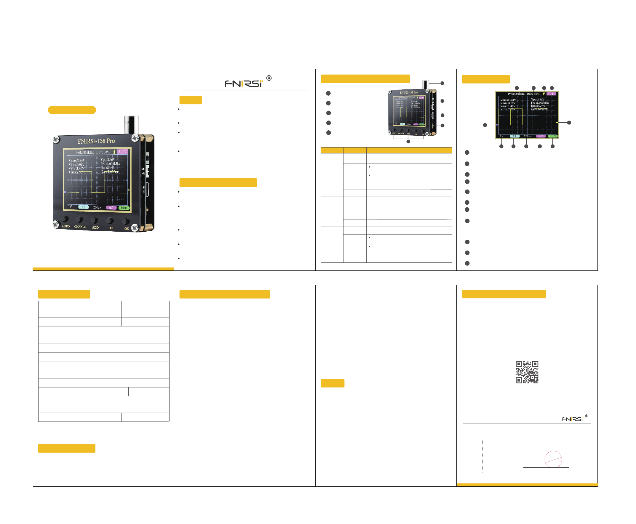
DIGITAL
OSCILLOSCOPE
FNIRSI-138 Pro
USER MANUAL
NOTE
Before using the product,Please read the manual carefully,in order to maximize
the performance of the product
Do not use this device in a flammable or explosive environment
Used batteries and discarded instruments replaced by instruments cannot be
disposed of with household waste.Please handle in accordance with relevant
national or local laws and regulations
When there is any quality problem with the instrument or when there is a
question about using the instrument,You can contact "FNIRSI" online customer
service or the manufacturer,We will solve it for you as soon as possible
PRODUCT INTRODUCTION
"FNIRSI-138PRO" is a highly practical,cost-effective,A cost-effective handheld
for the maintenance industry and the R&D education industry
The oscilloscope has a real-time sampling rate of 2.5MS/s, a bandwidth of
200KHz, a complete touch,Send function (single, normal, automatic).It works
perfectly for both periodic analog signals and aperiodic digital signals.Measures
voltages up to ±400V
Equipped with efficient one-key AUTO, the measured waveform can be
displayed without cumbersome adjustment
Equipped with a 2.4-inch high-definition LCD screen with a resolution of
320*240
Built-in 1000mAh high-quality lithium battery, can be used continuously for
about 4 hours after full charge
Panel And Button Introduction
BNC probe interface
1
2
RST reset switch
Type-C interface
3
4
0N/0FF switch
5
Function button
5
Button
AUTO
CHANGE
ADD
DIS
RST
*No key operation for 0.5 seconds, parameters will be automatically saved
Operate Function Description
Automatic adjustment (frequency below 20Hz
cannot be calibrated correctly)
Enter the automatic calibration confirmation
interface → press the 0K button
Enter automatic calibration mode (long press
AUTO again to cancel)
Toggle setting mode
Save key setting parameters
Move/change mode
Continuous movement
Move/change mode
Continuous movement
Pause/Start Waveform
In the vertical voltage gear position, long press
to switch X1/X10
In other cases, long press to show/close detailed
parameters
Reset restart
OK
Short press
Long press
Short press
Long press
Short press
Long press
Short press
Long press
Short press
Long press
Long press
1
2
3
4
Icon Indication
1
2 3 4
5
7 8 9 10
PWM square wave signal output frequency, the output range is adjustable
1
from 1-80KHz
PWM square wave signal output duty cycle, the output range is 0-100%
2
adjustable
Trigger edge indicator icon
3
Trigger mode indicator icon, Auto means automatic trigger, Single means
4
single, Secondary trigger , Normal means normal trigger
Baseline indication icon, this icon indicates the position that the current
5
position is OV voltage
Trigger voltage indicator icon
6
7
Vertical sensitivity, indicating the voltage represented by a large grid in the
vertical direction
1X/10X mode indicator icon, this must be the same as the 1X/10X on the
8
probe handle.The switch settings are the same. If the probe is in 1X gear,
then the oscilloscope should also be set to1X gear, 1X measures ±40V
voltage, 10X measures ±400V voltage
Horizontal time base, indicating the length of time represented by a large
9
grid in the horizontal direction
10
Input coupling mode indication icon, AC means AC coupling, DC means DC
coupling
11
Running pause indication icon, RUN means running, STOP means pause
6
11
Parameter Index
Powered By
Supply Voltage
Capacity
Sampling Rate
Bandwidth
Vertical sensitivity
Horizontal time
base range
Voltage Range
Trigger Modes
Coupling Modes
PWM output
Show
Size
Weight
*The size and weight are all measured manually, there are some errors, please refer to
the actual product
USB powered
5-6V
/
2.5MS/ s
10mV/Div-20V/Div (in 1-2-5 increments)
10μs/Div-50s/Div(in 1-2-5 increments)
X1:士40V (Vpp:80V) X10: 士400V (Vpp :800V)
Auto/Nomal/Single
F.R:0~80kHz Duty cycle: 0~100%3.3V
2.4 in/ PPI:320*240
66*71.6*22.8mm
53g (Without battery) 72g (Including battery)
lithium battery
4-9V
1000mAh
200K
AC/DC
Firmware Upgrade
1.Press the "OK" button to power on, you can enter the U disk upgrade mode
2.Use the Type-C cable to connect the Type-C port on the board to the
computer, then the computer will pop up a U disk belonging to "FNIRSI-138 Pro"
3.Pull the firmware into the U disk, and the firmware upgrade is complete
*Note: Firmware upgrade is only supported on WIN10 computer system
Analysis Of Common Problems
1、How to tell if the battery is fully charged?
A: When the battery is fully charged, the charging indicator will change from red
to green
2、Why can't I see a waveform when testing the signal, but
only see multiple lines jumping up and down?
A: The trigger mode can be set to "Auto", and then press the [AUTO] key again.If
still If it is not resolved, it may be that the clip on the probe is not grounded, or
the clip end of the probe is open circuited.
Please use a multimeter to check whether the probe is normal
3、Why does the tested waveform keep shaking left and
right and cannot be fixed?
A: The trigger voltage needs to be adjusted, that is, the yellow arrow on the
right.In trigger mode, press the up and down keys to adjust the trigger voltage.
After adjusting the yellow pointer between the upper and lower part of the
waveform, the waveform can be triggered and fixed
4、 Why is there no waveform when measuring a battery
or other DC voltage?
A: The battery voltage signal is a stable DC signal, and there is no curve
waveform.When adjusting the vertical sensitivity in DC coupling mode, there
will be an upward or downward offset line waveform.
If it is AC coupled, there is no waveform no matter how you adjust it
5、 Why is the VPP peak-to-peak data below 600V+, not 220V
or 310V, when measuring the 220V waveform of the mains?
A: Mains 220V is a symmetrical AC signal, the positive peak voltage (MAX) is
+310V, and the negative peak voltage (MIN) is -310V, so the peak-to-peak value
of VPP below is 620V.
The effective value (RMS) is the 220V voltage that is often
said, and the mains voltage RMS fluctuates between 180~260V, so the peak-to
-peak VPP is in the range of 507~733V
6、 Why is the measured mains 220V waveform not a very
standard sine wave, with distortion?
A: The mains power grid is generally polluted and contains more high-order
harmonic components.The superposition of these harmonics on the sine wave
will show a distorted sine, which is a normal phenomenon.
Generally, the mains waveform is distorted and has nothing to do with the
oscilloscope itself
7、 Why are the baseline (OV) and the left arrow (OV indicated)
on the screen different in position when there is no signal
input, and there is a relatively large offset?
A: Please unplug the probe and the USB cable, press the [AUTO] key to enter
the calibration confirmation interface, and then click the [OK] button to enter
the automatic calibration
NOTE
1.After receiving the device, please use it after it is fully charged
2.When using the oscilloscope, pay attention to the selection of the gear. The
gear of the oscilloscope should be consistent with the gear of the probe
3.When measuring high voltage, it is forbidden to touch any metal part of the
oscilloscope to avoid the risk of electric shock
4.Try not to perform high voltage test when charging
5.When calibrating, you need to unplug the BNC probe, or short-circuit the
positive and negative poles of the probe
6.USB firmware upgrade, only supports WIN10 and above, it is forbidden to
drag and drop files other than released firmware, otherwise it is very likely to
cause irreversible consequences
7.Please use the voltage within the specification range for charging
PRODUCTION INFORMATION
Product Name: Digital Oscilloscope
Brand/Model: FNIRSI/FNIRSI-138 Pro
Service Tel: 755-83242477
E-mail:[email protected]
Manufacturer: Shenzhen FNIRSI Technology Co., Ltd.
Address: 8th Floor, West of Building C, Weihuada Industrial Park,Dalang Street,
Longhua District, Shenzhen, Guangdong Province
www.fnirsi.cn
CERTIFICATE
Inspector:
Production Date:
QC
Pass
 Loading...