

Page 1

Weatherproof GSM telephone
FHF BA 9605-50 12/09
Operating manual
Page 2

2
Please note
Please read this user manual thoroughly before installing the device.
Check that all component parts were delivered.
Table of contents
General operating instructions......................................................................... 3
Original condition .................................................................................................... 4
Packaging content................................................................................................ ...... 4
Telephone default settings .......................................................................................... 4
Assembly and Installation ..................................................................................... 4
Wall mounting.............................................................................................................. 4
Battery connection................................ ....................................................................... 4
Solar panel or voltage supply connection................................................................... 4
SIM cards.................................................................................................................... 4
Serial port connection.................................................................................................. 5
Operating instructions ......................................................................................... 6
Control elements .......................................................................................................... 6
Key touchpad................................................................................................ ............... 6
Making / receiving calls ................................................................ ............................. 6
Dialing.......................................................................................................................... 6
Programming ............................................................................................................... 6
Setting call volume................................................................................................ ..... 7
Setting call melody................................................................................................ ...... 7
Setting speaker microphone sensitivity...................................................................... 7
Setting call reception volume................................................................ ...................... 7
Programming priority settings for SIM cards ............................................................... 8
Programming emergency numbers............................................................................. 8
Changing the password ............................................................................................... 8
Restoring default settings ............................................................................................ 8
Serial port (RS485) ................................................................................................... 9
General instructions............................................................................................... 10
Service................................................................................................ ....................... 10
Care and maintenance............................................................................................... 10
Warnings and safety instructions............................................................................. 10
Technical fact sheet................................................................ ................................. 11
Conformity declaration......................................................................................... 12
EMC guidelines................................ ................................ .......................................... 12
Page 3

3
General operating instructions
1. The Indutel GSM is intended for use with a solar panel or a DC voltage of 5V. An internal
battery serves as a voltage buffer. At least one SIM card is required for operation. The SIM
cards must have their PIN request deactivated.
2. The telephone has a receiver hook with a contact-magnet as hook switch. To end a phone
call, the receiver has to be placed back.
3. Telephone settings are programmed by sending information via SMS to the Indutel GSM.
4. Successful completion of programming is confirmed via a return SMS.
5. When the solar panel is in operation, the panel must be oriented in such a way that sufficient
charging of the battery is ensured. The battery discharge status is reported via SMS to the
number pre-programmed for this purpose.
6. When receiving calls, the Indutel GSM will ring at a volume and with the melody programmed
by you.
7. When programming the device settings, the four digit alphanumeric password must be within
the SMS text. This password can only be changed via SMS. If you forget your password,
please contact our technical support team.
8. A warranty period of 24 months applies from the date of purchase. If you experience technical
problems, please contact our technical support team in Germany, located in the city of
Muelheim an der Ruhr:
Telephone: +49 (0)208 82 68 102 · Fax: +49 (0)208 82 68 377 · Email: [email protected]
If a fault cannot be fixed over the phone, please send the apparatus and all accessories, as
well as a copy of the purchase receipt, to the following address:
FHF
Support Indutel
Gewerbeallee 15-19
45478 Muelheim an der Ruhr
Germany
Page 4
4
Original condition
Telephone default settings
Password
Call melody
Call volume
Receiver volume
Microphone sensitivity
0000
3
5
4
4
The default settings can be restored at any time via the programming function. This will not
however, change the new password.
Assembly and Installation
Wall mounting
Attach the mountings to the telephone using two screws for each. Use the M5 x 8 mm countersunk
screws supplied. Fasten the telephone with four screws (up to Ø 8 mm in diameter) to the wall.
Serial port connection
Take off the key touchpad together with the handset.
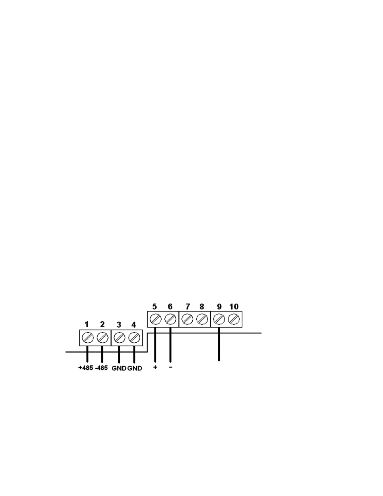
Connect the positive battery connector (red cable) to clamp 9.
Solar panel or voltage supply connection
Push the solar panel cable or DC voltage supply cable through a cable fitting and put the end of
the cable onto clamp 5 and 6 (Note: Observe polarity). Only use a cable with a cladding diameter
between 5 mm to 9 mm, otherwise the protection rating of IP 66 is not guaranteed.
SIM cards
Please insert the SIM card necessary for operation into one of the SIM card holders. If operating
with two SIM cards, please insert both SIM cards into the SIM card holders. The SIM cards must
have their PIN request deactivated.
Plug the flat ribbon cable with connector onto the pin header of the touchpad panel.
Screw on touchpad panel with the four screws.
Red cable
Battery
Connector clamps
Serial port
Solar panel
or DC voltage
supply
Page 5

5
Serial port connection (RS485)
* drilling
dimensions
The second cable entry point is intended for the serial port connection. Remove the key touchpad
and take the sealing element out of the cable entry point. Pass the cable through the cable entry
point and attach it to clamps 1, 2, 3 and 4. Fix the cable to the cable duct entry. Ensure that the
cable diameter meets the cable duct entry guidelines otherwise the IP protection rating is not
achieved. Then screw the key touchpad back on again using the four screws.
*
*
Page 6

6
Operating instructions
Control elements
Key touchpad
_________________________
Number key pads
Making / receiving calls
Dialling
When receiving a telephone call, lift the receiver to answer the call.
To make a call, lift the receiver and dial the number you would like to call.
Dialling
Enter the number you would like to call using the touchpad. The star key and the hash key are
neutral keys when making a call. Once the telephone number has been entered completely, press
the R key to connect to that number.
Page 7

7
Programming
Programming is done via SMS. A SIM card must be in the telephone to do this and the
telephone must be connected to a network. The SMS necessary for programming must be sent
to the Indutel GSM from another SMS enabled phone. The four (4) digit alphanumeric password
currently valid must be included in the SMS text. In the following text, the password is equal to
0000.
Upon successful programming, the Indutel GSM will send the following SMS:
FHFnnnnnn,OK; (nnnnnn: Telephone ID number; alpha numeric)
If programming was unsuccessful, the following SMS is returned:
FHFnnnnnn,ERROR; (nnnnnn: Telephone ID number; alpha numeric)
Setting call volume
SMS text: FHF0000,FHF+VOLRING,value;
value (0…4)
Setting call melody
SMS text: FHF0000,FHF+TYPERING, value;
value (0…7)
Setting speaker microphone sensitivity
SMS text: FHF0000,FHF+VOLMIC _HS, value;
value (0…9)
Setting call reception volume
SMS text: FHF0000,FHF+VOLSPK_HS, value;
value (0…9)
Page 8

8
SIM cards priority settings
The telephone always attempts to dial into the GSM net of SIM card 1.
SMS text: FHF0000,FHF+SIMCHK,SIM1,FIX;
The telephone always attempts to dial into the GSM net of SIM card 2.
SMS text: FHF0000,FHF+SIMCHK,SIM2,FIX;
The telephone first attempts to dial into the GSM net of SIM card 1. If this is unsuccessful,
it will attempt to dial into the net of the second SIM card.
SMS text: FHF0000,FHF+SIMCHK,SIM1,NOR;
The telephone first attempts to dial into the GSM net of SIM card 2. If this is unsuccessful,
it will attempt to dial into the net of the first SIM card.
SMS text: FHF0000,FHF+SIMCHK,SIM2,NOR;
Programming emergency numbers
SMS text: FHF0000,FHF+TNUM1,+49…..;
In an emergency, the programmed phone number receives an SMS, such as:
FHF000000,ALARM VBAT,3.41;
In this instance, the message says that battery voltage has fallen below a reliable value
and the GSM module in the telephone will be switched off.
Restoring default settings
SMS text: FHF0000,FHF&LDEFAULT;
When 'restoring default settings' the PIN will not be set back to 0000.
Changing the telephone ID number (default setting 000000)
FHF0000,FHF+SN, value;
Changing the password
SMS text: FHF0000,FHF+PSW,new password;
Saving the new parameters
After setting the parameters listed above, the following SMS must be sent to ensure that
those values are saved:
FHF0000,FHF&W;
Page 9

9
Serial port (RS485)
Communication protocol for connecting with an external device.
Sending
The Indutel GSM sends
STX (start of text, 02 hex)
The Indutel GSM waits for
DLE (data link escape, 10 hex) If a NAK (negative acknowledgement) or any other signal
is sent back as a DLE or there is a timeout, sending is
repeated 3 times. Sending is terminated after three
unsuccessful attempts.
After receiving the DLE, Indutel GSM transmits a data byte
Value and meaning of the data byte:
DLE
ETX (end of text, 03 hex)
and waits for
81 hex
82 hex
83 hex
84 hex
Ringing has started
Ringing has stopped
Receiver was lifted
Recover was replaced
Receiving
DLE If a NAK (negative acknowledgement) or any other signal is
sent back as a DLE or there is a timeout, sending is repeated
6 times. Sending is terminated after 6 unsuccessful
attempts.
The external apparatus sends
STX
and waits for
DLE
which is sent by Indutel GSM when it is ready to receive data.
After receiving the DLE, the external apparatus sends
1. Data byte
2. Data byte
DLE
ETX
value and meaning of the data byte C1 or C2
8 bit value
If transmission has been successful, Indutel GSM sends
DLE
If the data received is not correct or reception was impaired, Indutel GSM sends
NAK
requesting a repeat of the transmission. This request will be repeated 6 times. After 6 failed
attempts, sending will be terminated.
Receiving data should trigger an SMS which states:
Alarm1 (2), 2. Data byte.
Page 10

10
General instructions
Service
You have purchased a modern FHF product which is subject to a thorough quality control inspection.
If you have any questions about the telephone or if a malfunction appears - even after the guarantee
period - please contact FHF. Please have the model name and item number ready (see product
label).
If the internal battery needs to be exchanged, you will receive an appropriate replacement battery
from FHF including installation instructions.
Care and maintenance
The telephone is maintenance free. Nonetheless, in areas of operation that are heavily exposed to
dirt such as dust, fats, oils, etc., cleaning should be carried out from time to time. Use a moist
cleaning cloth to wipe down the apparatus and the receiver. Careful! Never use pointed objects to
clean the phone. Please avoid using other cleaning or scrubbing agents.
Adjustable casing components must NOT(!) be brought into contact
with grease or lubricants, e.g. fats and oils!
Warnings and safety instructions
This device is a weatherproofed telephone, made especially for operation in the rough conditions
of an industrial environment. The following warnings and safety instructions are to be observed:
1. The IP 66 protection rating is only guaranteed when the casing is closed.
2. The telephone is intended for operation connected to a solar panel or DC voltage. The
recommended voltage range is to be adhered to. Correct polarity connections are to be
observed. Connecting cables are to be positioned in such a way as to eliminate accident risk.
3. The telephone may only be operated under the environmental conditions indicated (see
Technical Fact Sheet). Adverse environmental conditions, such as extremely high or low air
temperatures are not acceptable because they promote failure of the telephone's electronic
components.
4. Ensure that the telephone, the connecting cable etc. are not damaged. Operation of the
telephone is not acceptable in damaged condition.
5. When operating the telephone, statutory and commercial guidelines, accident prevention
guidelines, as well as electrical regulations are to be observed.
6. For all repairs, only original parts are acceptable which must be installed by a qualified repair
person. Other kinds of replacement parts can cause damage. The guarantee is voided.
7. Prior to a repair or replacement of the telephone, the voltage supply must be disconnected.
The internal battery must also be disconnected. If maintenance or repair under voltage is
unavoidable, only qualified personnel may carry it out.
8. The sealing elements necessary to ensure the casing is sealed must not be damaged during
assembly and disassembly.
9. The recommended operating position (wall mounted) is to be observed.
10. Changes to this product that serve as technical improvements, may be made without prior
notice.
Page 11

11
Technical fact sheet
GSM frequency bands
Voltage supply
Solar panel
Maximum power supply
Battery
Nominal voltage
Standard capacity
Temperature range charging
Quad Band, GSM850, GSM 900, GSM1800, GSM1900
5 VDC + 10%
from solar panel or DC voltage supply
10W recommended, open circuit voltage ≤ 6.9 VDC
500 mA
Lithium Ion
3.75V
approx. 5 Ah
-20°C to +60°C
Temperature range discharging -50°C to +60°C
Operating time
Talk time
Standby
Operation
Ringing volume
Casing
Height x width x depth
Weight
(telephone incl. telephone holder)
Operating position
Receiver
Speaker capsule
Receiver capsule
Connections
Operating environment temp.
Transport and storage temperature
With fully charged battery
Approx. 21 hours
Approx. 30 days
With one or two 2 SIM cards
With open casing cover
Approx. 90 dB(A) at a distance of 1 m
With closed casing cover
Approx. 65 dB(A) at a distance of 1 m
330 x 237 x 110 mm
2.3 kg
Vertical wall mounted
Electret microphone
Dynamic capsule
Single-wire or multi-wire up to 2.5 mm2
-25°C to +55°C
-25°C to +70°C
Protection rating as per IEC60529 IP66 (IP65 open casing)
Cable fitting
for cable diameter
2x M16 x 1.5
5 ÷ 9 mm
Page 12

Conformity declaration
FHF Funke + Huster Fernsig GmbH confirm that the InduTel telephone is in conformance
with the fundamental requirements and other relevant provisions of guideline 1999/5/EU
(R&TTE).
However, should problems occur during operation, please contact the technical support
team at FHF.
EMC (Electro Magnetic Compatibility) Guideline
The device meets the requirements of the new EMC guideline 2004/108/EG, the Low
Voltage guideline 2006/95/EG and the R&TTE guideline 1999/5/EG.
Conformity to the guidelines listed above is verified by the C E (Conformité Européenne) sign.
Electronic devices and old electrical items with this symbol may contain hazardous
substances. For this reason they may not be disposed of together with regular domestic waste.
To protect the environment, public collection stations are available for the disposal of electronic
devices and old electrical items with this symbol.
Subject to alterations
or errors
FHF Funke+ Huster Fernsig GmbH
Gewerbeallee 15-19 · D-45478 Mülheim an der Ruhr
Phone +49 /208 /82 68-0 · Fax +49 /208 / 82 68-286
http://www.fhf.de · e-mail: [email protected]
 Loading...