

Page 1
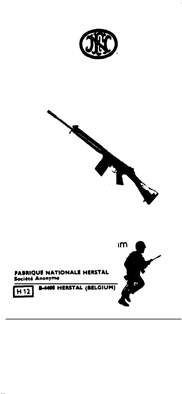
FAL
USER’s MANUAL
LIGHT AUTOMATIC RIFLE
CAL. 7.62 mm
FADRlQUt NATlONALlE HtltSTAL
Soci4tb
Anonym
” ,1
0
u400 HEWAL (NLCIUM)
f
Page 2
I.
INTRODUCTION
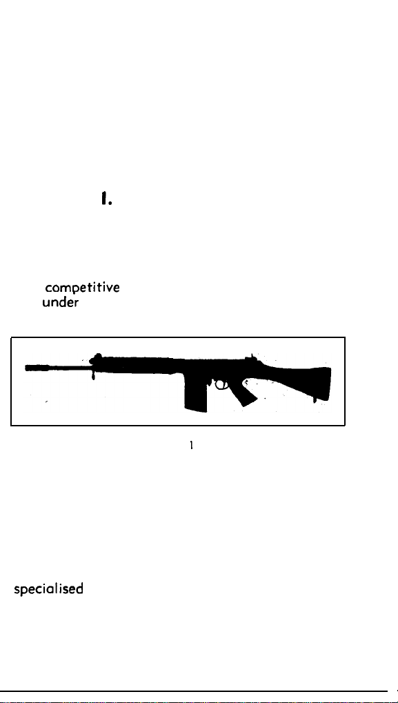
The FN Light Automatic Rifle, colibre 7.62 mm
NATO, usually known OS the “F. A. L.” or
“L. A. R.“,
and
comoetitive
and unde; all types of climatic conditions.
This rifle, which has been adopted by many
countries both within and outside NATO, was
designed and made by FN to give the user a
rifle which would combine all the essential qua-
lities needed under modern fighting conditions, to
a hitherto unequalled degree.
This booklet is neither for the armourer nor the
specialised officer:
the user with a weapon which is new to him and to
put sufficient knowledge at his disposal to enable
him to use it with maximum efficiency.
has resulted from prolonged research
trials made in various countries
Fig.
I
its purpose is to familiarise
3
Page 3
I I. CHARACTERISTICS
AND TECHNICAL DETAILS
The FN Light Automatic Rifle is an automatic
weapon, calibre 7.62 mm NATO, gas-operated and
with a breech block which is mechanically locked
before firing can take place.
Rifle
Weights
1.
a) Rifle without magazine: 4.325 kgs
prox. 9.53 Ibs)
b) Magazine (steel) empty: 250 g
c) Magazine (steel) filled 20 rounds Ball
Ammn.: 730 g (1 lb 98 ozs)
d) Barrel. approx.
Measurements
2.
a) Overall length
b) Barrel length
c) Sight radius
System of operation: gas, with regulator and
3.
piston.
Method of feed: 20-round
4.
Magazine housing : underneath the receiver.
5.
Ejection opening
6.
4
800 g (1 lb
1,090 mm (approx. 40”)
.
533 mm (approx.
.
553 mm (approx. 21$“)
.
magazme.
right side of receiver.
:
(8+ ots)
12a
ozs)
(ap-
21N)
Page 4
7.
Cocking handle:
8.
Chonge lever: left side of trigger frame.
9.
Sights: adjustable, bocksight graduated from
200-600 metres, scaled by 100 m.
Rifling of barrel : 4 grooves, direction-right,
10.
pitch-l in
11.
Cyclic rote of fire: 650-700 rpm.
12.
Operational rate of fire, semi-automatic: up
to 60 rpm.
left side of receiver.
305
mm (1 in
12”!
Cartridge
1.
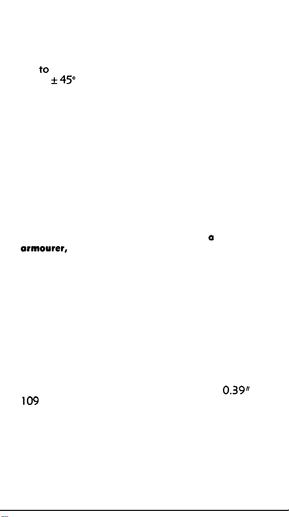
Colibre: 7.62 mm NATO (Fig. 2).
2.
Weight of cartridge: (for ordinary ball round
“SS
77”) approx. 24 g (0.86 oz).
3.
Length of cartridge: 7 I mm
4.
Weight of ordinary bullet: “FN SS 77”:
9.30 g (0.33 oz).
(2.8”).
Powder charge:
5.
lnitiol Velocity (VO) in the “F. A. L.“:
6.
840
m/set
Muzzle Energy (EO) in the “F. A. L.“:
7.
335 kgm (2,422
8.
Remaining Kinetic Energy at 600 metres
(656 yds): 100 kgm (723
N. 6. For further technical information and
ballistical chorocteristics, also firing tables, refer
approx. 3 g (0.1 oz).
(2,754 ft/sec).
ft.lbs).
ft.lbs).
5
Page 5
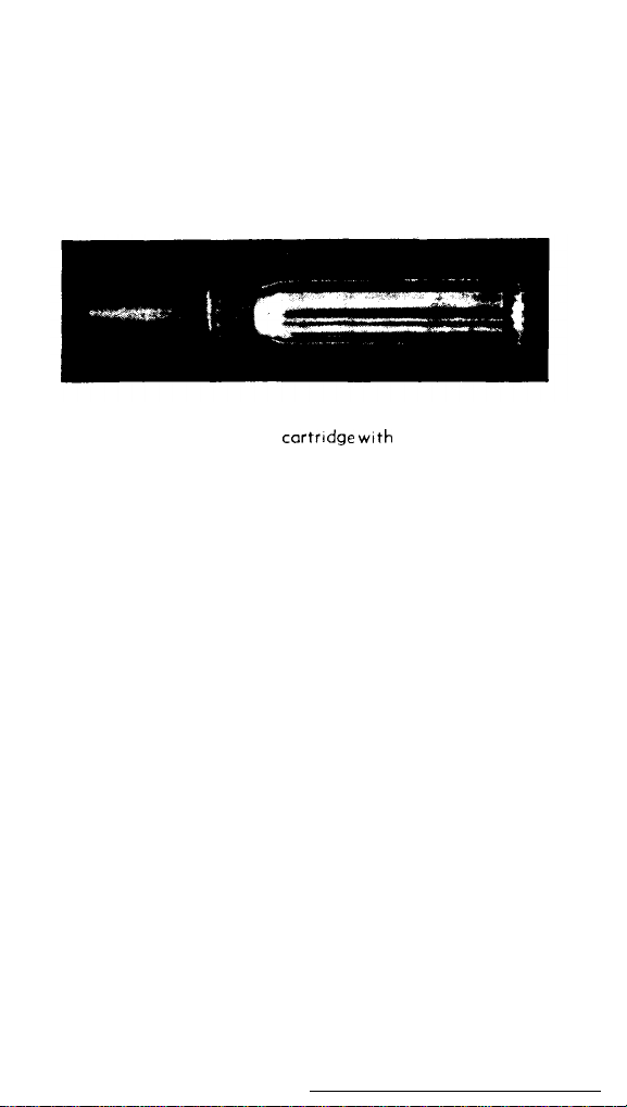
to FN booklet for Ammunition calibre 7.62 mm
NATO, or other handbook on thk subject.
Fig. 2
FN 7.62 mm NATO
cartrldge wtth
SS 77 bullet
6
Page 6

III.
FUNCTIONING
1. COCKING
Before firing, the breech block mechanism is
forward, with the safety applied (change lever set
at
‘5”).
Insert a filled magazine obliquely in the housing
under the receiver, swing it from front to rear and
push fully home:
in the rifle at both front and rear.
Pull the cocking handle, on the left side of the
receiver, fully to the rear, then let it go forward: a
cartridge is thus introduced into the chamber;
the rifle is loaded and cocked.
To fire, set the change lever either at “R” for
semi-automatic fire, or at “A” for automatic fire.
2. REAR MOVEMENT OF THE MECHANISM
Pressing the trigger fires the shot.
When the bullet passes the gas port in the barrel, port of the combustion gases penetrate the
regulator and thence into the gas cylinder.
piston is projected to the rear, strikes the
block slide, which is also driven rearwards.
recoiling a few millimetres, the ramps of the slide
force the rear part of the breech block to rise,
thus lifting it out of engagement with its locking
the magazine is then. secured
The.
breech-
After
7
Page 7

shoulder in the receiver.
unlocked. The recoil of slide dnd breech block
continues, the extractor removes the spent case
from the chamber: extraction is completed; then
the hammer, pushed by the slide, is forced to pivot
to the rear.
As recoil continues, the base of the spent case
contacts the ejector, an integral part of the receiver; the case is then thrown out of the gun to the
right, through the ejection opening.
buring this rear movement, the return springs,
housed in the butt, are compressed by the slide
rod,
hinged to the rear of the slide.
The piston has returned to its forward position,
as its
spl’ing
relaxed.
3. FORWARD ACTION OF THE MECHANISM
The mechanism is then
The return springs, compressed during the rear
movement of the mechanism, now relax and drive
the breech block assembly forward. The breech
block pushes the next cartridge towards the cham-
ber, while the hammer is held in the cocked
position by the safety sear: the front of the
breech block contacts the rear portion of the bar-
rel; the cartridge is chambered and the base of
its case seized by the extractor claw.
The slide acts on the upper shoulder of the
breech block and forces its rear end downwards,
causing its lock shoulder to engage in the locking
recess in the receiver. The mechanism is now
lacked.
The slide continues its forward movement alone:
towards the end of its course, the safety sear is
tripped by the shoulder on the rear left underside
of the slide, which causes the sear to pivot and the
hammer to be released; the rear end of the firing
8
Page 8

pin protrudes beyond the rear face of the slide,
when the front face of the slide is.fully home.
In automatic fire, it is the safety sear which
releases the hammer and thus causes the shot to
be fired, because the trigger sear is not in action
in this case, except for the first shot of each burst
of fire.
In semi-automatic fire, it is the trigger sear
which finally releases the hammer, after it has
first been released by the safety sear; the mechanism has been so designed that the trigger
must be released, then pressed again, to permit
the following shot to be fired (see 4 below).
4. CHANGE LEVER
The lever arm can occupy one of the three fol-
lowing positions:
a) An uppermost position “5” when the rifle is
at safe:
in this position, if the trigger is pressed,
it is impossible to fire because the rounded part of
the change lever arm is over the trigger platform,
preventing it from rising to engage the tail of the
sear.
b) A front position “A”, which sets the mecha-
nism at automatic fire: before firing the rear tip
of the trigger is now so positioned in relation to
the deeper bent in the change lever axis that
pressing the trigger causes the sear to pivot
up-
words: the nose of the sear is consequently disen-
gaged from the hammer bent and firing takes
place.
In addition, the nose of the trigger sear has
been swung downwards so that it cannot contact
the hammer, which is controlled by the safety
sear only, so long as the trigger is not released;
OS
firing depends on the safety sear, this frees
9
Page 9
the hammer each time the mechanism closes after
the breech is completely locked: firing is auto-
matic,
When the firer releases the trigger, the nose
of the sear rises, catches hold of the hammer,
which then pushes the sear slightly to the rear;
this positions the tail of the sear over the heel of
the trigger and the mechanism is then cocked,
ready to fire the next burst.
c) A rear position “R”, which sets the
mecho-
nism at semi-automatic (single shot); the rear tip
of the trigger is now against a shallower bent in
the change lever than in position “A”, pressing
the trigger therefore pivots the sear to a lesser
degree so that after the first shot has been fired,
the hammer will be caught by the sear. This
moves slightly forward under the action of its
spring and is thus placed in front of the heel of the
trigger, i.e. no longer in contact.
Firing another
cartridge is therefore impossible if pressure on the
trigger is maintained.
To continue firing, the trigger must be released;
when this is done, the hammer turns slightly under
action of its spring;
OS
it is in contact with the
sear, it pushes the sear towards the rear so that
the tail of the sear comes over the heel of the
trigger; pressure on the trigger will now fire the
second shot, and so on.
Note
:
If automatic fire is not required, the
change lever can be removed and another change
lever fitted with indent for semi-automatic fire
only, i.e. with 2 instead of 3 settings.
Any sol-
dier can easily make this substitution.
10
Page 10

5. HOLDING OPEN DEVICE
When the magazine is empty, its platform
pushes the holding open device upwards, in the
pathway of the breech block, which is thus held
to the rear, and the firer knows that his magazine
is empty.
ed, depress the lever of the holding open device
so that the breech block is released and can continue its forward movement.
After a filled magazine has been insert-
.
11
Page 11

IV. HANDLING
1. FILLING MAGAZINE
a) With Magazine Filler
Each rifle is usually supplied with a magazine
filler.
-
Fit the magazine filler over the mouth of
the magazine, with the guides for the loading clip on the side of the magazine rib
12
Fig. 3
Page 12

-
Insert a loaded clip into the reor guide of
the magazine filler (fig. 3).
-
With the thumb as near as ‘possible to the
clip, force the rounds down into the maga-
zine.
b) Without a Mogarine Filler
-
If the rounds are in clips, take them out.
-
Insert the cartridges one by one into the
magazine, with the base of the round to
the rib of the magazine.
c)
Note
-
After filling a magazine, particularly when
a magazine filler has not been used, it is
advisable to check the positioning of the
.
cartridges in the magazine by pressing
down with the thumb on the last round
inserted.
-
In the event of one or more cartridges not
sliding freely inside the magazine (jamming of the point of a round against the
front wall), a correct positioning of all the
cartridges can be obtained by striking the
rear wall or on the bottom of the magazine
lightly with the palm of the hand.
2. CHARGING
-
Insert a filled magazine front end foremost
into the magazine housing (fig. 4).
-
Swing the magazine into position and push
fully home.
13
Page 13
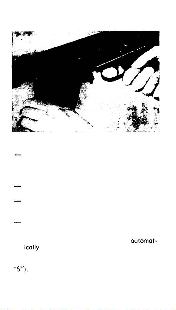
Fig. 4
-
The magazine is then secured at the rear by
the magazine catch.
LOADING
3.
-
Take hold of the pistol grip with the right
hand.
-
With the left hand, pull the cocking handle
(on the left side of the receiver) to the rear and
then release it.
-
The forward movement ‘of the breech block
will have extracted a cartridge from the maga-
zine, chambered it and then locking of the
moving parts will hove taken place
ically. The rifle is now ready to fire.
Note: During charging and loading operations,
the rifle will be kept at safe (Change lever set at
“5”).
14
automot-
Page 14
4. RELOADING
After the lost round in the magazine has been
fired, the holding open device, operated by the
magazine platform, keeps the mechanism to
the rear (see page 11).
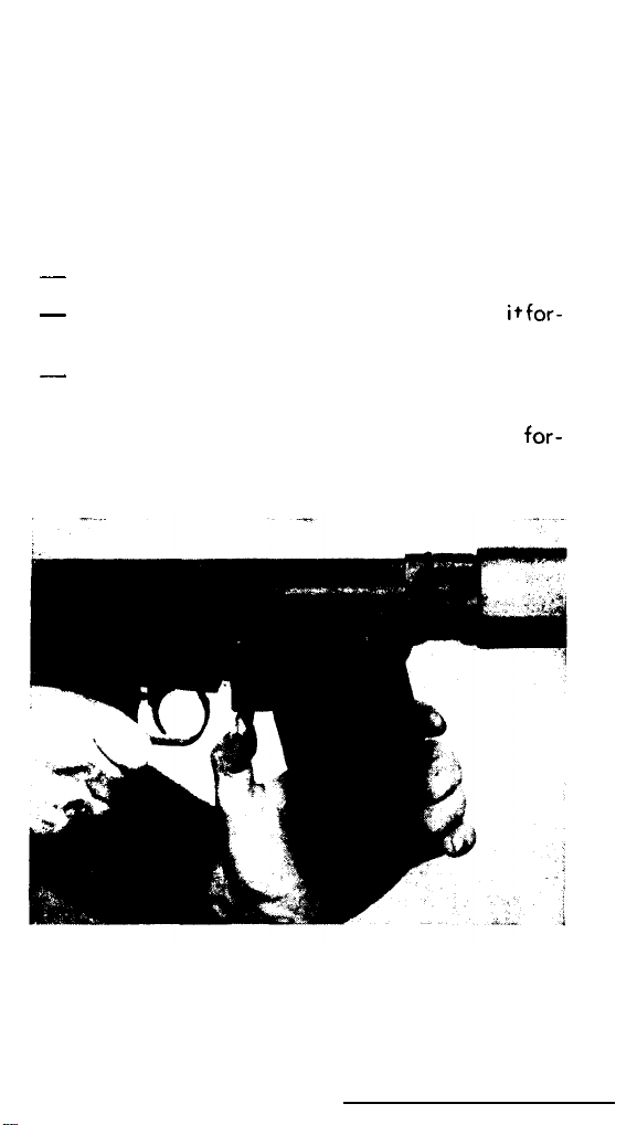
-
Press the magazine catch (fig. 5).
-
-
Remove
words.
Insert 0
Depress
(fig. 6);
ward.
the empty magazine, swinging it for-
filled magazine.
the lever of the holding open device
the breech block will then move
for-
Fig. 5
15
Page 15
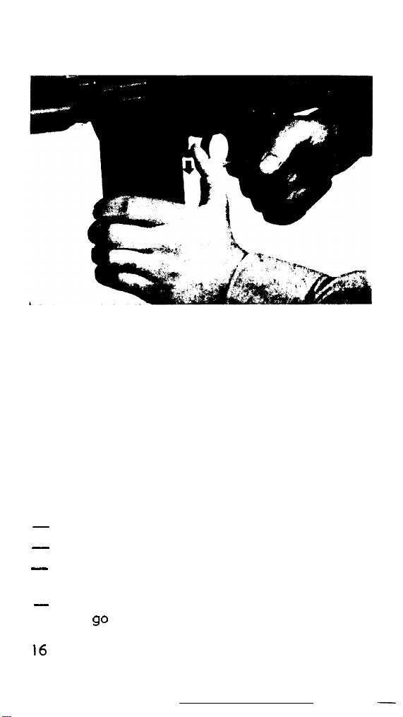
Fig. 6
The rifle is now ready to fire again.
5. UNLOADING
-
Put the rifle at safe (change lever set at “S”).
-
Remove the magazine.
-
Pull the cocking handle fully back to extract
and eject the cartridge in the chamber.
-
Release the cocking handle and let the mecha-
nism go forward.
16
-
Page 16
6. FIRING SINGLE SHOT
-
Insert a filled magazine.
-
Use the tip of a cartridge to push the plunger
in the gas plug fully down and hold it in this
position (fig. 22).
-
Turn the cartridge and the gas plug 180” so
that the letter “G” appears on top, instead of
the letter “A”.
-
Let the plunger return to its housing (the notch
in the plug is towards the bottom).
-
Carry out the loading operations (see
-
After firing each shot, repeat the loading ope-
page
rations.
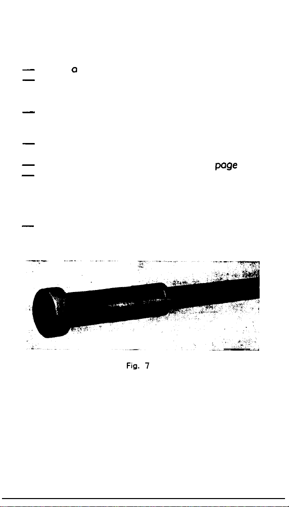
7. FITTING THE BLANK FIRING DEVICE
-
This device is to be screwed on the tapped end
of the combined device (fig. 7).
14).
8. GAS REGULATION
The purpose of the gas regulator is to ensure
correct functioning of the rifle with maximum gas
escape, or, in other words, the minimum intake
17
Page 17

necessary for normal functioning, without causing
undue wear on the various parts of the mechanism.
Turning the gas regulator to the right (clockwise) reduces the opening by which gas escapes,
thus increasing the quantity or “intake” gas used
to drive the piston to the rear.
Turning the gas regulator to the left (anti-
clockwise) causes the opposite effect: gas escape
is increased and the balance available to work the
piston is decreased.
By a system of “clicks” and engagement of the
gas regulator spring, the regulator has 13 different
positions (12 “clicks” to open fully).
To make setting in any given position easier,
figures are engraved on the gas regulator, the
figure 1 corresponding to the completely closed
position and one figure for every 2 “clicks” open-
ing.
Example: when the figure 5 is opposite the
gas hole, the gas regulation corresponds to
8 “clicks”.
o)
Method of gas setting
There are several different ways of finding the
correct adjustment but we suggest the following
method, which has, we think, proved itself the
best :-
- Insert an empty magazine in the rifle;
-
All firing is carried out by inserting the car-
tridges by hand, one by one into the empty
magazine, through the ejection opening.
-
The correct setting is determined by the
point at which the holding open device
engages the mechanism and holds it to the
rear, or fails to do this.
18
Page 18
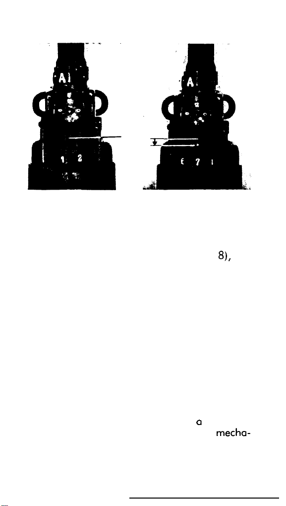
Fig. 8 Fig. 9
b) Operations
Operation 1. After
right down against
screwing the gas regulator
the gas block (fig.
8),
un-
screw by one complete turn so that the figure 7
is in line with the axis of the gas escape hole
(fig. 9).
This is the fully open position and,
when a round is fired, causes a “short recoil”,
identifiable by the holding open device failing
to engage the mechanism.
Operation 2. Close the gas regulator click by
click and fire a cartridge after each adjustment
until the breech block is held to the rear by the
holding open device.
Operation 3. Now verify by firing several car-
tridges, one after the other, in the way described
above.
Operation 4. If any shot results in a failure of
the holding open device to engage the
mecha-
19
Page 19
nism, repeat Operation 3, after closing the gas
regulator by one click.
Operation 5.
If necessary, repeat Operation 4
until 5 consecutive shots result in the holding
open device holding the mechanism to the rear
5 times.
Operation 6. The gas setting for the rifle is now
determined, but it is always advisable to allow
a small reserve of “working” gas by reducing
the gas escape by two additional clicks.
Note
-
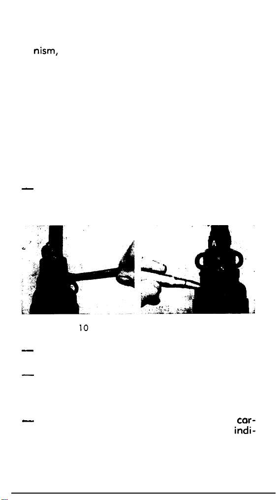
If the special spanner (fig. 10) is not available,
adjustment can be made with the point of a
cartridge (fig. 1 I), or even by hand.
Fig.
IO
-
Before leaving the factory, every rifle has been
Fig. 1 1
adjusted for correct gas setting.
-
In principle, the soldier should not alter the
gas setting; this operation ought to be done
in the presence of the unit armourer, or an
instructor.
-
In practice, the force with which the spent
tridge case is ejected gives on invaluable
20
cor-
indi-
Page 20
cation of the gas setting.
An ejection of cases
to a distance of 1.50-2 m from the rifle and
at f 45” in relation to the barrel axis can be
considered normal.
Violent ejection shows
that too much gas is being admitted and, in
this event, the gas escape must be increased.
On the contrary, weak ejection shows that
insufficient gas is being taken in and, in this
case, the gas escape should be reduced.
ZEROING
9.
The rifle is zeroed, i.e. the sights are correctly
adjusted, before issue to the user but it may require
some attention to correct for elevation and direction to suit individual needs.
Such correction must be done by a qualified
armourec,
or on instructor, who will have the spe-
cial tools to do this.
a) Correction for Elevation
Errors in elevation are corrected by screwing the
foresight up or down. If it is screwed up, the
M. P. I. will be moved down and vice-versa.
A spring detent locates and holds the foresight
in position, which forms a clicking device with the
16 equal divisions serrated under the foresight collar; this assists the armourer when calculating
movement of the M. P. I. Moving the foresight
1 division (or click) is equal to a variation in
M. P. I. of 1 cm at 100 metres (approx.
0.39”
at
109 yds).
b) Correction for Direction
Errors in direction are corrected by moving the
backsight to the right or left.
21
Page 21

If the M. P. I. is to the right of the point sighted, the screw on the left of the sight is loosened
and the screw on the right is screwed up, thus
moving the sight laterally along its dovetail from
right to left.
When the correction has been made, and before
shooting, tighten both screws.
If the M. P. I. is to the left of the point sighted,
the sight must be moved from left to right.
A movement of 1 division (or click) is equal to
a
variation in M. P. I. (to right or left) of 1 cm at
100 metres (approx. 0.39” at 109 yds).
10. STOPPAGES AND IMMEDIATE ACTION
The FN Light Automatic Rifle is unlikely to
be affected by variations in normal ammunition.
Obviously, this means good quality ammunition
because a bad cartridge will give rise to stoppages,
whatever the weapon that fires it.
Tighten the screw on the left.
Stoppages are generally of two
1. Those caused by fouling, due to the user’s
negligence, or ignorance of his rifle, or lack of
lubrication (modern powders of good quality
cause very little fouling).
2. Those caused by some mechanical deficiency
(less frequent).
A mechanical stoppage, other than that caused
by an empty magazine, can usually be remedied
by taking immediate action, without stopping to
investigate its cause.
types:-
22
Page 22

Procedure for immediate action
-
Remove the magazine;
-
Pull the cocking handle fully to the rear and
release; do this twice;
-
Replace the magazine;
-
Load (recock the rifle by pulling the cocking
handle to the rear and releasing so that a new
round is fed into the chamber);
-
Resume firing.
If the stoppage recurs, consult the armourer or
instructor to find out the cause.
23
Page 23
V. GRENADE LAUNCHING
The F. A. L. is equipped with a combined device,
serving as both flash-hider and grenade-launcher;
with this fitment, anti-tank and anti-personnel gre-
nades can be launched with great accuracy.
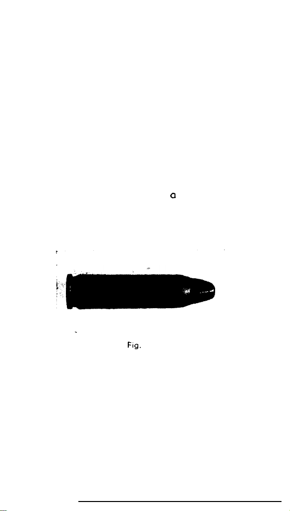
.
Fig.
12
1. CARTRIDGE
A special type of ammunition is used, generally
known as a propulsive, or grenade, cartridge. This
cartridge has no bullet and the mouth of the case
is closed by a “star” crimping which is waxed to
ensure complete tightness (fig. 12).
24
Page 24
HANDLING
2.
Put the rifle at SAFE.
I.
Unload (chop. IV, 5).
2.
Set
3.
the rifle for firing single shot (see chap-
ter IV, 6).
With the left hand, cock the rifle.
4.
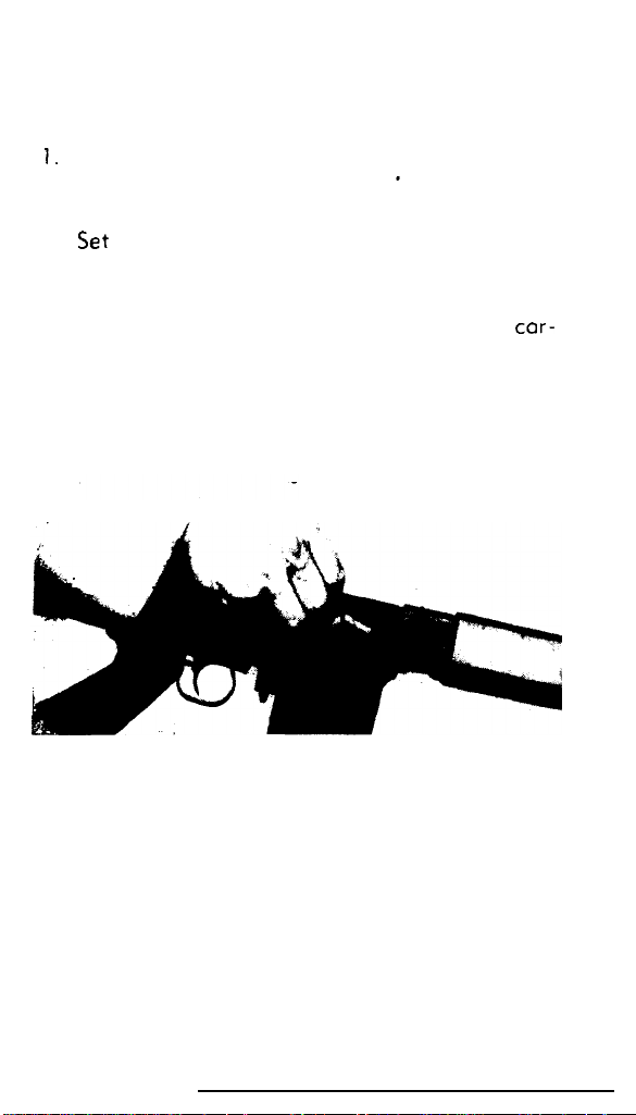
With the right hand,
insert the propulsive cor-
tridge in the chamber (fig. 13).
Let the mechanism go forward (it is easier if
the muzzle of the gun is held downwards).
Fig. 13
Put the grenade on the launcher and make
5.
sure that it is fully home
Releose the safety from the rifle and, as re-
6.
quired, remove the grenade safety. The rifle
is then ready to fire.
25
Page 25
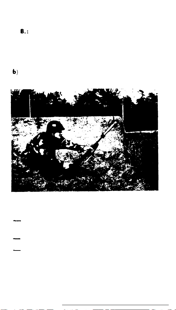
3. FIRING POSITIONS
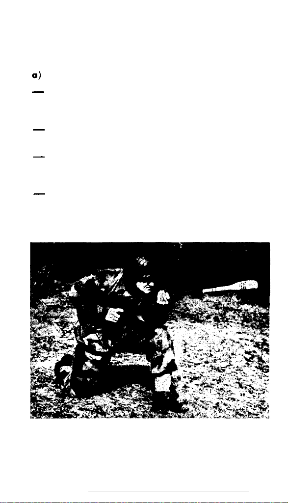
Direct fire (fig. 14)
0)
-
For the 3 usual positions (standing, kneeling,
prone) the method of holding the rifle is the
some.
-
Grasp the middle of the handguard firmly with
the left hand.
-
Hold the pistol grip firmly with the right hand,
with the index finger securely in front of the
trigger.
-
Hold the butt under the right armpit, never
lean it on the shoulder.
26
Fig. 14
Page 26
N.
6.:
A sling can be used to help take the recoil
but this is left to the discretion of the user.
b)
Indirect fire (fig. 15)
Fig. 15
-
Dig the heel of the butt
the pistol grip uppermost,
-
Incline the rifle at the required angle.
-
Hold the foot down on the front of the butt to
prevent it from moving out of position.
into the earth, with
i.e. towards the firer.
27
Page 27

Note: So far as possible, it is advisable to avoid
positioning the butt against any hard surface, such
as concrete, rock, etc. This is particularly important for indirect fire from the prone position, where
the soldier naturally tends to anchor the fore part
of the butt to avoid the effects of recoil.
,
:.
28
Page 28

VI. FIELD STRIPPING
The soldier should know the field stripping routine so well thot it con be carried out in darkness.
For this stripping, he will need to use the nose of
a
cartridge;
-
Remove the magazine.
-
Cock the mechanism to ensure that the rifle
is clear and there is no round left in the cham-
ber, allow the breech block to go forward and
set the change lever at safe, leaving the hammer cocked.
STRIPPING THE MECHANISM
1.
-
Press the body locking lever (on the left side)
as far as possible upwards; at the same time,
press the butt/trigger frame group down-
wards, which will swing the rifle open like a
shotgun (see fig. 16).
-
Remove the slide-breech-block assembly by
taking hold of the slide rod hinged to the slide
(fig. 17).
no other tools are required.
29
Page 29
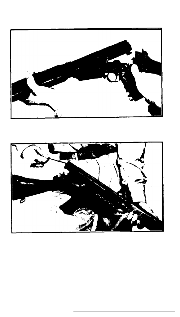
Fig. 16
Fig. 17
2. REMOVING THE COVER
Slide the receiver cover to the rear (fig. 18).
30
Page 30
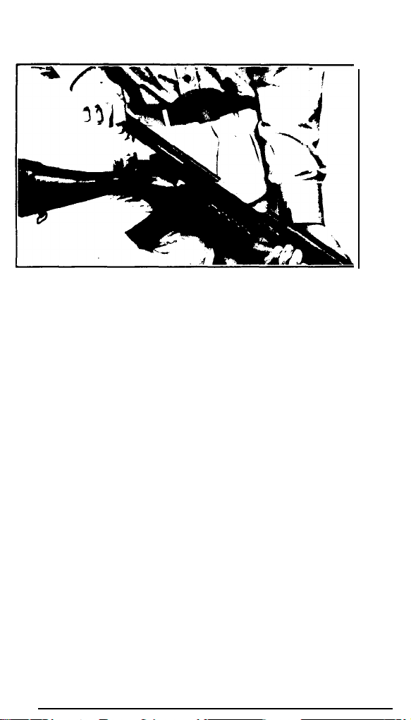
Fig. 18
3. SEPARATING THE SLIDE FROM THE BREECH
BLOCK
Disengage the fore part of the breech block
from the slide and continue to separate with a
levering movement against the rear part of the
breech block, keeping the thumb on the rear end
of the firing pin (fig. 19).
4. REMOVING THE FIRING PIN
Exert pressure on the rear end of the firing pin
and push out its retaining pin.
not fall out easily, use the nose of a cartridge to
push it out (fig. 20).
If the pin does
31
Page 31
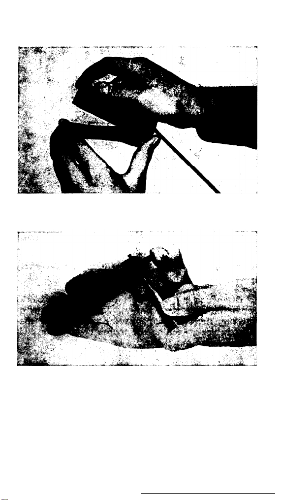
Fig. 19
Fig. 20
When the retaining pin has been removed, the
firing pin will come out of its housing under action
of its spring (fig. 21).
32
Page 32
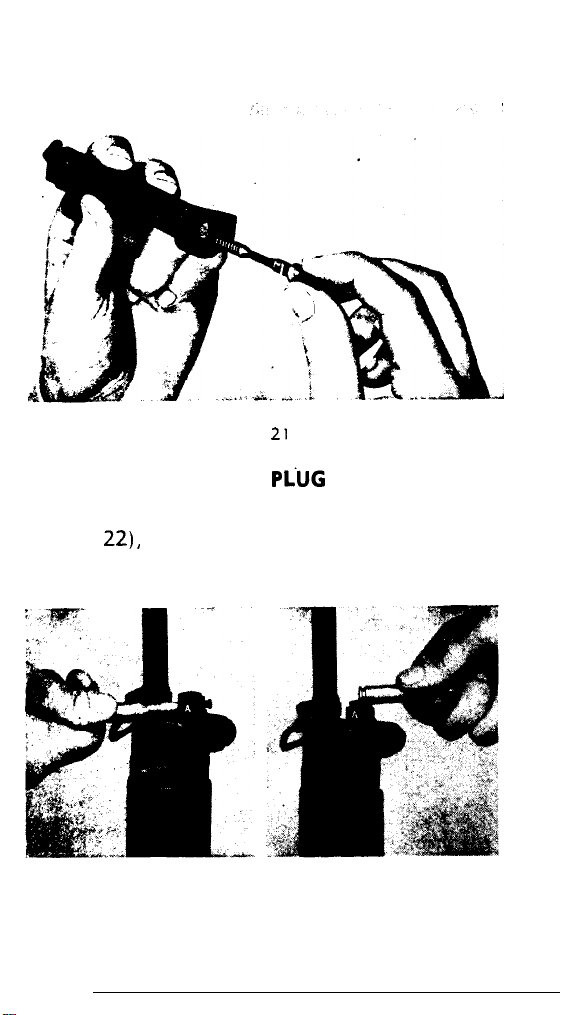
Fig. 21
5. REMOVING THE GAS
PiUG
Use the nose of a cartridge to press in the plun-
ger (fig.
in a clockwise direction (fig. 23).
22),
then turn the gas plug a quarter turn
Fig 22
Fig. 23
33
Page 33
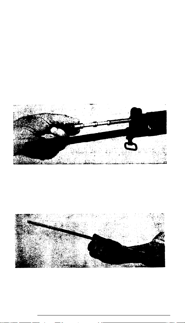
In this position, the plug will be pushed from
its housing by the piston spring.
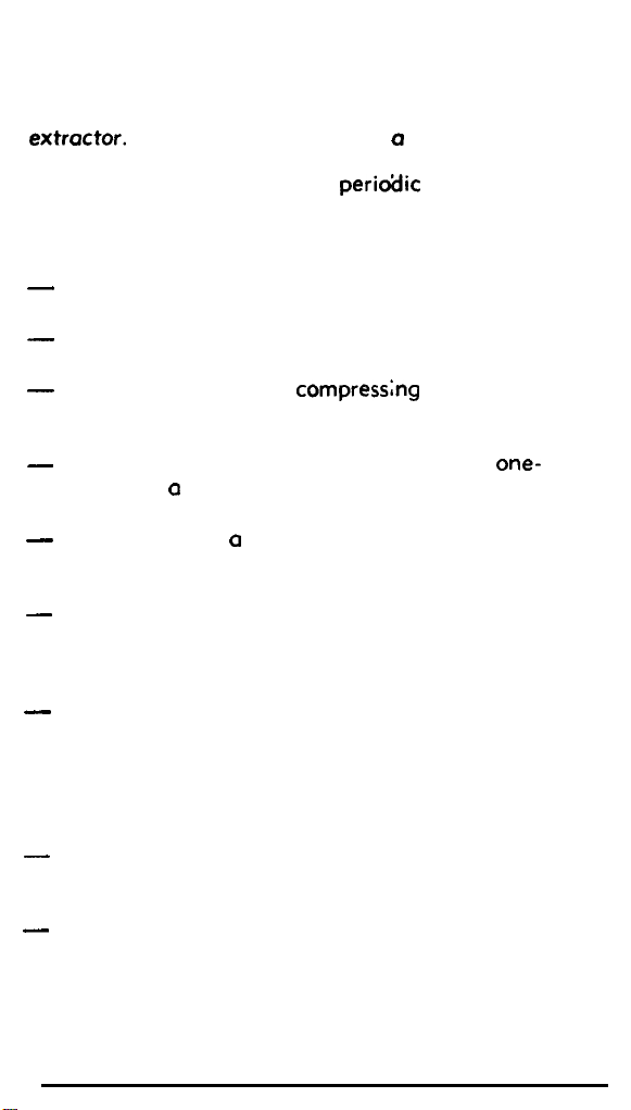
6. REMOVING THE PISTON
Remove the piston and its spring from the gas
cylinder (fig. 24).
Fig. 24
Separate the piston spring from the piston rod
(fig. 25).
34
Fig. 25
Page 34
Note: There is no need for the soldier to strip the
extractor.
It is necessary to use a cartridge for
this, or a special tool, and it is normally done by
the armourer when making o
perio?Jic
inspection.
7. ASSEMBLY AFTER FIELD STRIPPING
-
Replace the piston spring on the piston rod
(fig. 25).
-
Replace the piston and its spring in the gas
cylinder (fig. 24).
-
Insert the gas plug,
compressng
the piston
spring, with the big end of the plunger turned
towards the barrel (fig. 23).
-
When the gas plug is fully home, rotate it
one-
eighth of a turn, so that the letter “A” moves
upwards.
-
Use the nose of a cartridge to push the plunger
and rotate so that the letter “A” appears
uppermost (fig. 22).
-
Replace the firing pin spring and the firing
pin in the breech block (fig. 21); compress
the spring by working the firing pin and replace
the pin.
-
Replace the breech block in the slide, inserting
the rear part obliquely in the slide (fig. 19).
Exert pressure on the breech block so that the
firing pin spring is slightly compressed and the
breech block is swung downwards into its cor-
rect position in the slide.
-
Insert the ribs of the cover in the correspond-
ing grooves in the receiver (fig. 18) and slide
the cover fully forward.
-
Replace the mechanism in the body, inserting
the ribs of the slide in the corresponding
35
Page 35

grooves in the receiver.
When this is done, the
breech block should be in its forward position
(fig. 17) and the muzzle of the rifle pointing
downwards; the mechanism will then fall into
position correctly.
-
Close the rifle, still holding the muzzle downwards, to prevent any possibility of the slide
rod protruding.
36
Page 36

VII. CLEANING AND MAINTENANCE
1.
GENERAL REMARKS
It must be emphasized that all automatic weapons require constant cleaning and maintenance
and that most of the stoppages mentioned else-
where are the result of the soldier’s negligence
or lack of knowledge of his weapon.
whether automatic or repeating rifles, should be
cleaned at the end of a day’s firing and special
core must be taken after firing with blank cartridges.
2. MAINTENANCE OF THE RIFLE
a) Maintenance by the soldier
The FN Rifle cal. 7.62 mm only needs to be
partially stripped for this maintenance (field
stripping); maintenance routine is 0s follows:-
-
Use the barrel cleaning brush, oiled with the
special rifle
the barrel several times:
-
Follow this by pulling through two or three
dry rags;
-
Clean the chamber with the cleaning brush
provided for this purpose;
bore
oil provided, and pass through
All weapons,
37
Page 37

Clean the slide, rear of the barrel and inside
the body;
Clean the breech block, firing pin and its housing;
Clean underneath the extractor claw, without
stripping it;
Remove the gas plug, the piston and its spring
and carefully clean these parts, as they are
exposed to gas fouling;
Clean the gas cylinder and wipe with a slightly oiled rag; this rag should also be passed
through the barrel;
Very slightly oil the moving parts of the me-
chanism.
Inspection and maintenance by the unit ar-
mower
It is essential that the rifle should be examined
periodically by the armourer, who will check that
it is being properly cared for by the user.
All components of the rifle will then be checked
for correct functioning. When this examination
is made, the following special cleaning and inspection operations will also be carried out:-
-
Cleaning the exhaust port in the gas cylinder;
-
Stripping and cleaning the extractor;
-
Checking the gas setting;
-
Checking the sight and correcting, if necessary.
’
38
Page 38
3.
COMPLETE
CLEANING OF BARREL AND GAS
CYLINDER
The barrel and gas cylinder must be cleaned
regularly so that they never get into such a state
that the use of abrasives is necessary; all abra-
sive material such as emery paper, sand, etc., is
always harmful.
The full cleaning of barrel and gas cylinder
should be done unhurriedly, when circumstances
permit, 0s follows:
Wash the barrel, using barrel brush, or sponge,
steeped in special oil.
Wash the inside of the front part of the gas
cylinder and gas block, using the brush for
cleaning the chamber and the special oil.
After the barrel and gas cylinder have been
thoroughly cleaned in this way, dry carefully,
using clean rags. After drying, the
usually white service flannelette-should come
out of the barrel and gas cylinder unstained.
After drying, slightly oil the barrel (bore and
chamber) and the gas cylinder.
Dry the outside of the barrel and polish with
a greasy rag.
The pieces of flannelette for this cleaning will
usually be cut to the tollowing measurements:
length approx. 120 mm, width approx. 60 mm
(about 5”
For possing through the barrel, use an unfolded
piece, for cleaning the gas cylinder, double it over
to give a
loop of the cleaning rod or pullthrough.
Rags or cotton waste can be used for cleaning
the remaining parts of the rifle.
x2+“).
60x60
mm square before inserting in the
rag-
39
Page 39

Note: The inside of the barrel and inside of front
half of the gas cylinder come into direct contact
with the combustion gases and are also submitted
to friction;
and attention. Other components are protected
against oxidising by phosphating (parts of the
mechanism and receiver) and the piston and gas
plug are hard chromed.
Precaution after firing
To be on the safe side, particularly in hot cli-
mates, and to make subsequent cleaning of barrel
and gas cylinder easier, the user is strongly advised
to take the following preventive measure:
Immediately ofter firing, before leaving the
firing range or scene of manceuvres, clean barrel
and gas cylinder by wiping with a rag steeped in
special oil (Rifle bore oil).
This precaution has the effect
Neutralising the harmful effect of any fouling
caused by residue of powder gases;
Preventing the formation of carbon deposits in
the gas cylinder ond gas block;
Allowing the usual cleaning operations to be
postponed for at least 24 hours, without
causing any damage.
Within 48 hours of carrying out this precaution,
the rifle should be completely cleaned as indicated
in paragraphs 2 and 3.
they consequently require more care
of:-
40
Page 40
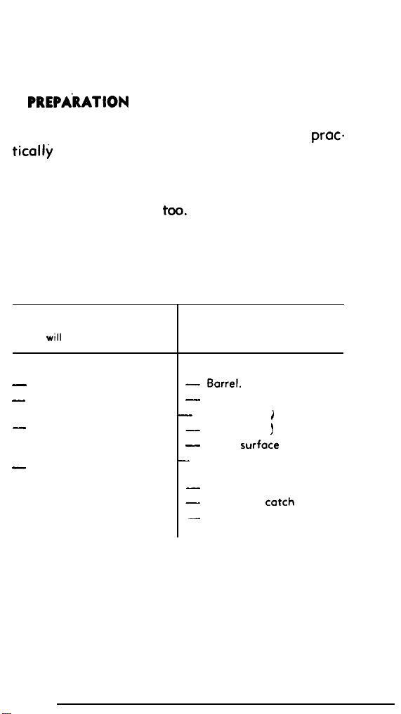
4.
PREPAkATlON
OF RIFLE BEFORE FIRING
The L. A. R. functions with very little or
ticolly
no lubrication.
proc-
Before firing, wipe off any oil remaining on barrel and gas cylinder surfaces; if the piston and
chromed part of the gas plug have been slightly
oiled, dry clean these
too.
The tabulation given below gives on one side
the list of parts which can be slightly oiled, on the
other the list of parts which require no oiling and
which, in some cases, can be adversely affected,
if oiled.
Components,
or ports of components,
which
wtll
be very slightly oiled
OILED
-
Inside breech block slide.
-
Breech block, ot locking
shoulders.
-
Body, at bottom ond
olong guide grooves for
slide.
-
Holding open device.
or parts of components, which
will not be oiled before firing
LEFT DRY
- Barrel.
-
-
Piston.
-
-
-
Front face of breech
-
-
-
Components,
Gos cylinder.
i
Gos Plug. ) ports
Outer surface of slide.
block.
Mogorine and plotform.
Magazine
Sights.
chromed
catch
41
Page 41
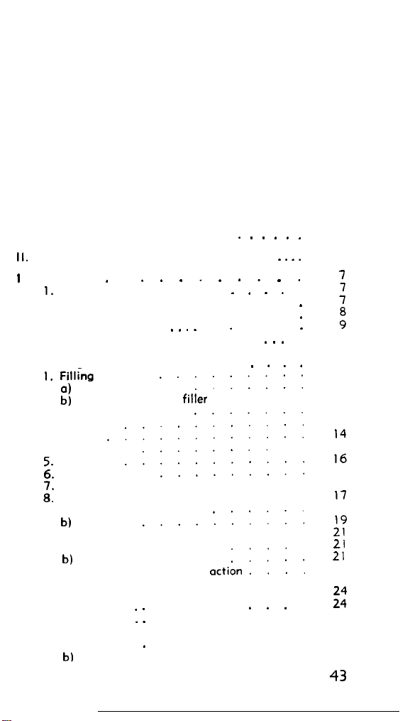
INDEX
I. Introduction
II.
Characteristics ond Technical Details
I I I. Functioning
I.
Cocking
2. Rear movement of the mechanism
3. Forward action of the mechanism
4. Change lever
5. Holding open device
IV. Hondling
Fillbtg Magazine
I.
a)
With magazine filler
b)
Without magazine
c) Note on checking
Charging
2.
Loading
3.
Relooding
4.
Unloading
Firing single shot
;:
Fitting the blonk firing device
Gas regulation
::
a) Method of gas setting
b)
Operations
Zeroing sights
9.
a) Correction for elevation
b)
Correction for direction
10.
Stoppages and immediate
V. Grenade Launching
I. Cartridge
2. Handling
3. Firing positions
a) Direct fire
b)
Indirect fire
. . . . . . . . .
.
. . . .
.........
......
......
filler
.......
..........
............
........
...........
.........
..........
......
..........
..........
action
. .
. .
.
. . . .
.
....
....
.....
. . . . . .
. . . .
. . .
. . . .
....
. . *
3
4
7
:
.
.
:
.
11
12
12
12
13
13
13
I4
15
I6
17
17
I7
18
::
21
21
22
tl:
25
26
26
27
43
Page 42
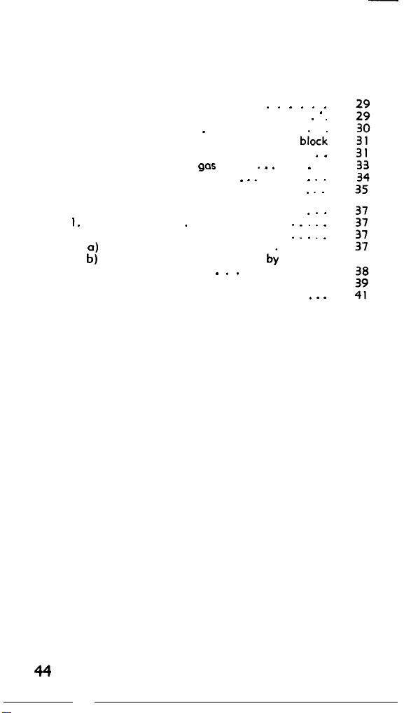
VI Field Stripping
1. Stripping the mechanism
2. Removing the cover
3. Separating the slide from the ‘breech block
4. Removing the firing pin
5. Removing the gas plug
6. Removing the piston
7. Assembly after field stripping
VII. Cleoning and Maintenance
I. General remarks
2. Maintenance of the rifle
a)
Maintenance by the soldier
b) Inspection and Maintenance by the unit
armourer
3. Complete cleaning of barrel and gas cylinder
4. Preparation of rifle before firing
.
.
. . .
. . . . . .
. . . .
. . .
: : : 1 :
. ‘.
. .
.
. .’ :
. . .
. . .
44
 Loading...