

Page 1
FMUSER INTERNATIONAL GROUP INC. 广州市汉婷生物技术开发有限公司
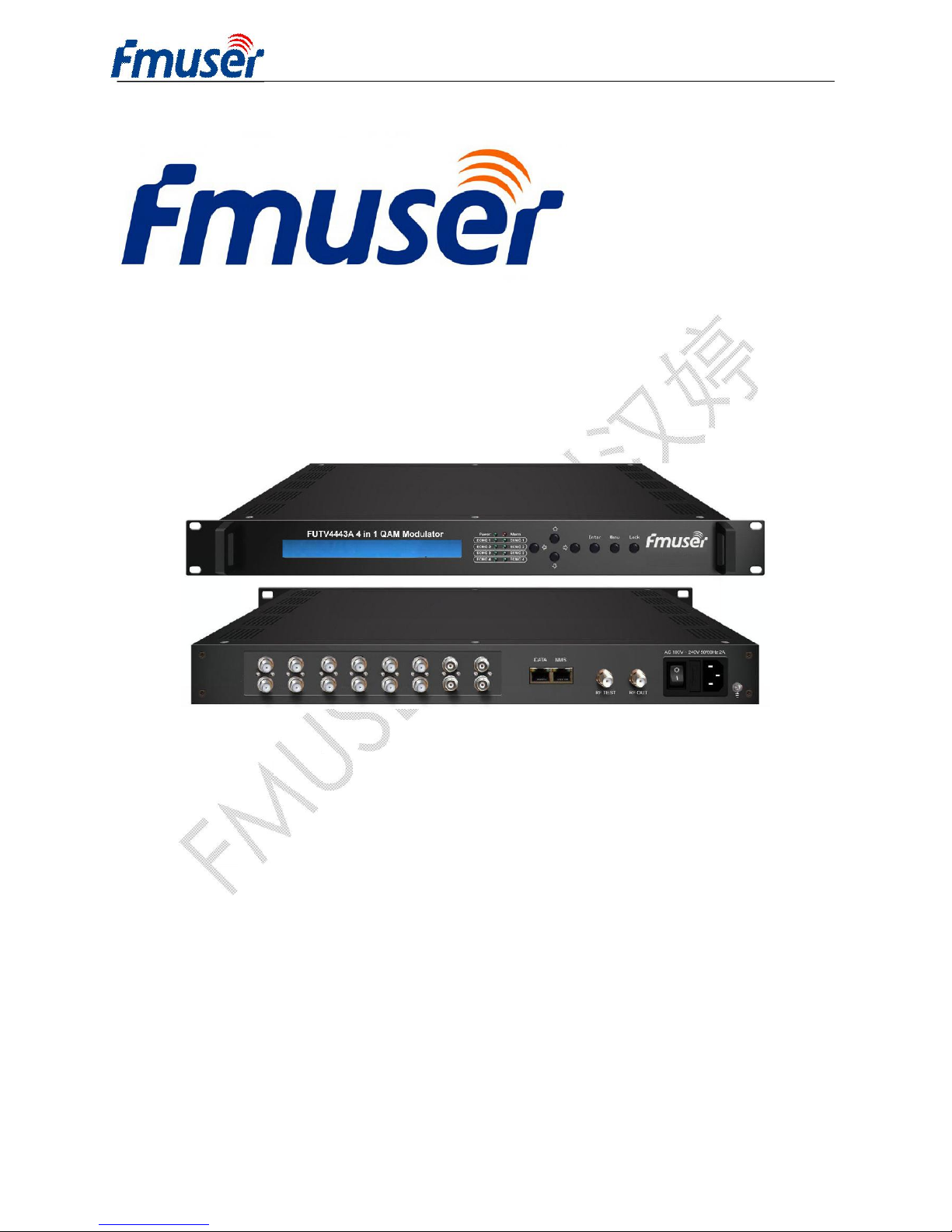
FUTV4443A-10 4 in 1 Mux-Scrambling QAM
User’s Manual
NMS Version: 3.3.8
SW: 0.12
HW: 2.1
Page 2
FMUSER INTERNATIONAL GROUP INC. 广州市汉婷生物技术开发有限公司
Directory
Chapter 1 Product Outline .............................................................. …………..3
1.1 Outline ............................................................................................................................................. 3
1.2 Features .......................................................................................................................................... 3
1.3 Specifications .................................................................................................................................. 4
1.4 Principle chart ................................................................................................................................. 5
Chapter 2 Appearance and Illustration .......................................................... 5
2.1 Front Panel: ..................................................................................................................................... 5
2.2 Rear Panel: ..................................................................................................................................... 6
Chapter 3 Installation Guide ............................................................................ 6
3.1 Acquisition check ............................................................................................................................ 6
3.2 Installation Preparation ................................................................................................................... 6
Chapter 4 Operation ....................................................................................... 10
4.1 LCD Menu Tree............................................................................................................................. 11
4.2 Main Interface ............................................................................................................................... 13
Chapter 5 SNMS Setting................................................................................. 21
5.1 Installation ..................................................................................................................................... 21
5.2 Software Operation ....................................................................................................................... 21
5.3 4443A 4 in 1 Mux-Scrambling QAM Operation ............................................................................ 26
5.4 Out Setting .................................................................................................................................... 34
5.5 Real-time Monitor .......................................................................................................................... 35
5.6 EIT Time ........................................................................................................................................ 35
5.7 Parameters .................................................................................................................................... 36
Chapter 6 Troubleshooting............................................................................ 38
Chapter 7 Packing List ................................................................................... 39
Page 3

FMUSER INTERNATIONAL GROUP INC. 广州市汉婷生物技术开发有限公司
3 / 39
Chapter 1 Product Outline
1.1 Outline
FUTV4443A is a cost effective integrated 4 in 1 QAM modulator supporting
multiplexing and scrambling. This device supports maximum 6 DVB-S2 tuner+4
ASI input, after 4 multiplexer and 4 scrambler processes, then gives 4 carriers
output (4 adjacent frequency by 1 RF port) and gigabit IP output. The device is
characterized with high integrated level, high performance and low cost. This is very
adapting to newly generation CATV broadcasting system.
1.2 Features
l Support 6 DVB-S2 tuner+4 ASI input optional
l Fully support DVB-C (EN300 429) and ITU-T J.83A/B/C
l Fully support DVB general scrambling system description ETR289, simulcrypt
standard ETSI 101 197 and ETSI 103 197
l Support 4 channels multiplexing, 4 channels scrambling and 4 channels QAM
modulating
l Support gigabit IP output
l Simultaneously support 4 simulcrypt CA
l Support accurate PCR adjusting
l Support PSI/SI editing and inserting
l Excellent RF output performance index, MER≥40db
l Support LCD display and keyboard
l Support SNMP management
Page 4
FMUSER INTERNATIONAL GROUP INC. 广州市汉婷生物技术开发有限公司
4 / 39
1.3 Specifications
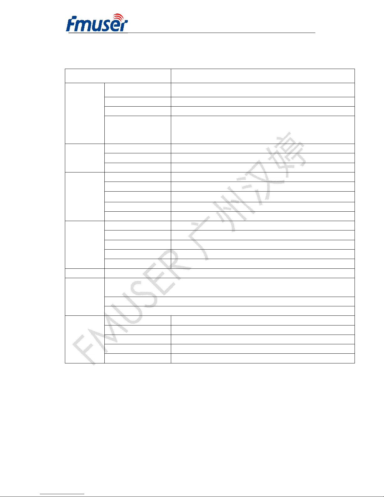
Input
6 DVB-S2 tuner+4 ASI input
Multiplexer
Input 6 DVB-S2 tuner+4 ASI input
Output Channel 4 RF output
Max PIDs 256 per channel
Functions
PID remapping(auto/manually optional)
PCR accurate adjusting
PSI/SI table automatically generating
Scrambling
Max simu-encrypt CA 4
Scramble Standard ETSI 101 197,ETSI 103 197
Connection Local/remote connection
QAM
Modulation
QAM Channel 4
Modulation Standard EN300 429/ITU-T J.83A/B/C
Symbol Rate
2.5Msps~4.66Msps, 5.0Msps~8.0Msps,1ksps stepping
Constellation 16、32、64、128、256QAM
FEC RS (204, 188)
RF Output
Interface F typed output port for 4 carriers, 75Ω impedance
RF Range 48~1000 MHz,1kHz stepping
Output Level
-25dBm~6dBm,0.5dB stepping(
-16dBm~-0dBm)
MER ≥ 40db
ACLR (Adjacent Channel Leakage Ratio) − 60 dBc
IP Out Gigabit
System
Support LCD display, keyboard operation, and NMS/SNMP operation. English and Chinese
operation interface conversion
English and Chinese interface conversion
Ethernet software upgrade
General
Demission (W*L*H) 482mm×455mm×44.5mm
Weight 6.7kg
Temperature 0~45℃(operation),-20~80℃(storage)
Power Supply AC 100V±10%,50/60Hz or AC 220V±10%,50/60Hz
Consumption 25W
Page 5
FMUSER INTERNATIONAL GROUP INC. 广州市汉婷生物技术开发有限公司
5 / 39
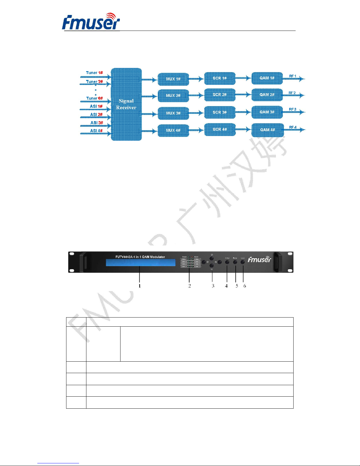
1.4 Principle chart
Chapter 2 Appearance and Illustration
Indicator area: All the indicators will light on when the 4 in 1 Mux-Scrambling QAM
works at current state.
2.1 Front Panel:
1 LCD Display
2
Indicator
Area
POWER:Power Indicator
Alarm:Alarming Indicator
ECMG1/2/3/4 Indicator
EMMG1/2/3/4 Indicator
3 Up/Down/Left/Right Key
4 Enter:Confirmation Key
5 Menu Key
6 Locking Key
Page 6
FMUSER INTERNATIONAL GROUP INC. 广州市汉婷生物技术开发有限公司
6 / 39
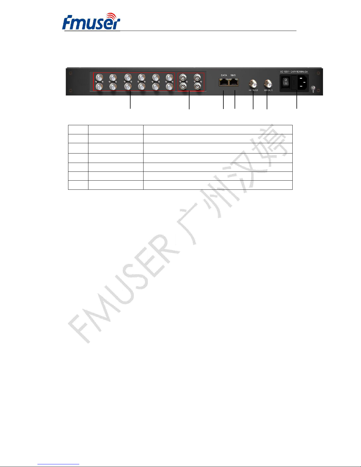
2.2 Rear Panel:
1 2 3 4 5 6
7
1 Tuner 1-6 IN Channel 1-6 Tuner Input
2 ASI 1-4 IN Channel 1-4 ASI Input
3 Data IP Port
4 NMS NMS Interface
5 RF TEST RF Test Interface
6 RF OUT RF Out Interface
7 Power Power Socket
Chapter 3 Installation Guide
3.1 Acquisition check
When users open the package of the device, it is necessary to check items
according to packing list. Normally it should include the following items:
l FUTV4443A 4 IN 1 Mux-Scrambling QAM 1pc
l User’s Manual 1pc
l Tuner wire 5pcs
l ASI wire 4pcs
l Grounding wire 1pc
If any item is missing, please inform local dealer.
3.2 Installation Preparation
When users install device, please follow the below steps. The details of
installation will be described at the rest part of this chapter. Users can also refer
rear panel chart during the installation.
Page 7
FMUSER INTERNATIONAL GROUP INC. 广州市汉婷生物技术开发有限公司
7 / 39
The main content of this chapter including:
1 Checking the possible device missing or damage during the transportation
2 Preparing relevant environment for installation
3 Installing 4 in 1 Mux-Scrambling QAM
4 Connecting signal wires
5 Connecting communication port (if it is necessary)
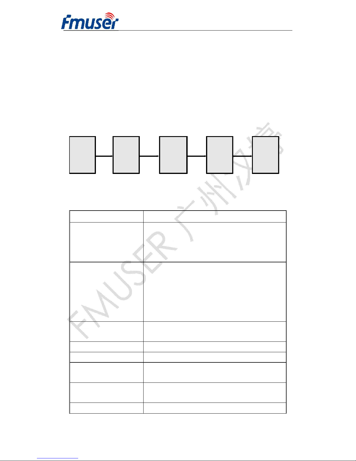
3.2.1 Device’s installation flow chat illustrated as following
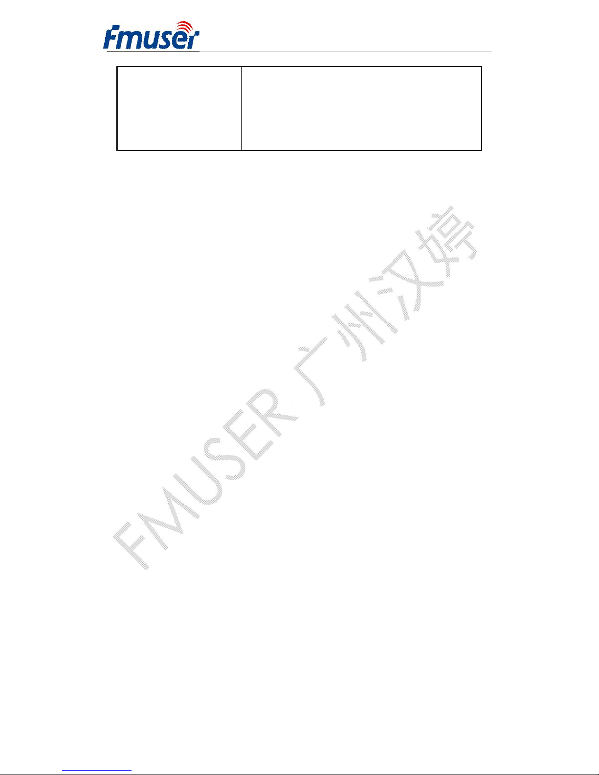
3.2.2 Environment Requirement
Item Requirement
Machine hall space
When user install machine frame array in one
machine hall, the distance between 2 row of
machine frames should be 1.2~1.5m and the
distance to wall should be no less than 0.8m。
Machine hall floor
Electric Isolation, Dust Free
Volume receptivity of ground anti-static
material:1×10⁷~1×10
10Ω
,Grounding current
limiting resistance: 1MΩ。
Floor bearing should be greater than
450Kg/m
2
。
Environment
temperature
5~40°C sustainable,0~45°C short time
installing air-conditioning is recommended
Relative humidity 20%~80% sustainable 10%~90% short time
Pressure 86~105KPa
Door & window
Installing rubber strip for sealing door-gaps
and dual level glasses for window
Wall
It can be covered with wallpaper, or bright
less paint.
Fire protection Fire alarm system and extinguisher
Connecting
Grouding
Wire and
Power
Cord
Acquisition
Check
Fixing
Device
Setting
Parameter
Running
Device
Page 8
FMUSER INTERNATIONAL GROUP INC. 广州市汉婷生物技术开发有限公司
8 / 39
Power
Requiring device power, air-conditioning
power and lighting power are independent to
each other. Device power requires AC power
100V-240V 50/60Hz 2A Please carefully
check before running.
3.2.3 Grounding Requirement
All function modules’ good grounding designs are the base of reliability and
stability of device. Also, they are the most important guarantee of lightning
arresting and interference rejection. Therefore, system must follow this rule:
1. Coaxial cable’s outer conductor and isolation layer should keep sound electric
conducting with the metal housing of device.
2. Grounding conductor must adopt copper conductor in order to reduce high
frequency impedance, and the grounding wire must be as thick and short as
possible.
3. The 2 terminals of grounding wire must make sure for well electric conducting,
and process for antirust.
4. It is prohibited that users use other devices as part of grounding wire’s electric
circuit
3.2.3.1 Frame Grounding
All the machine frames should connect to protective copper strip. The grounding
wire should be as short as possible and avoid circling. The section of the
conjunction between grounding wire and grounding strip should be equal or
greater than 25mm2.
3.2.3.2 Device Grounding
User can connect the device’s grounding rod to frame’s grounding strip with
copper wire.
3.2.4 Wires’ Connection
The power supply outlet is located at the right of rear panel, and the power switch
is just above it. The protective grounding wire connective screw is located at the
down-right side of power supply outlet.
Page 9
FMUSER INTERNATIONAL GROUP INC. 广州市汉婷生物技术开发有限公司
9 / 39
1. Connecting power cord
2. User can insert one end into power supply outlet, while insert the other end to
AC power.
3. Connecting grounding wire
4. When the device solely connects to protective ground, it should adopt
independent way, say, sharing the same ground with other devices. When the
device adopts united way, the grounding resistance should be less than 1Ω
FCaution: Before connecting power cord to 4 in 1 Mux-Scrambling QAM,
user should set the power switch to “OFF”.
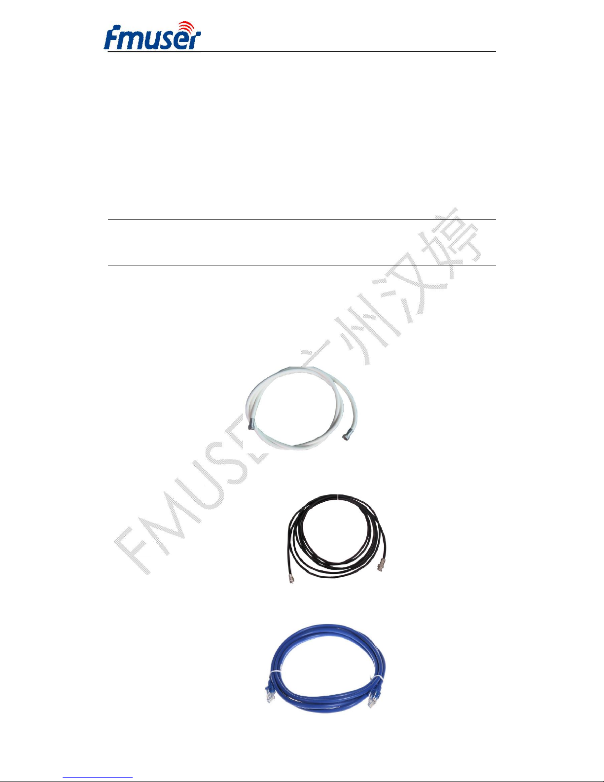
3.2.4.1 Signal Cable Connection
The signal connections include the connection of input signal cable and the
connection of output signal cable. The details are as follows:
l Tuner Cable Illustration:
l ASI Cable
l IP Input/output Cable Illustration:
Page 10
FMUSER INTERNATIONAL GROUP INC. 广州市汉婷生物技术开发有限公司
10 / 39
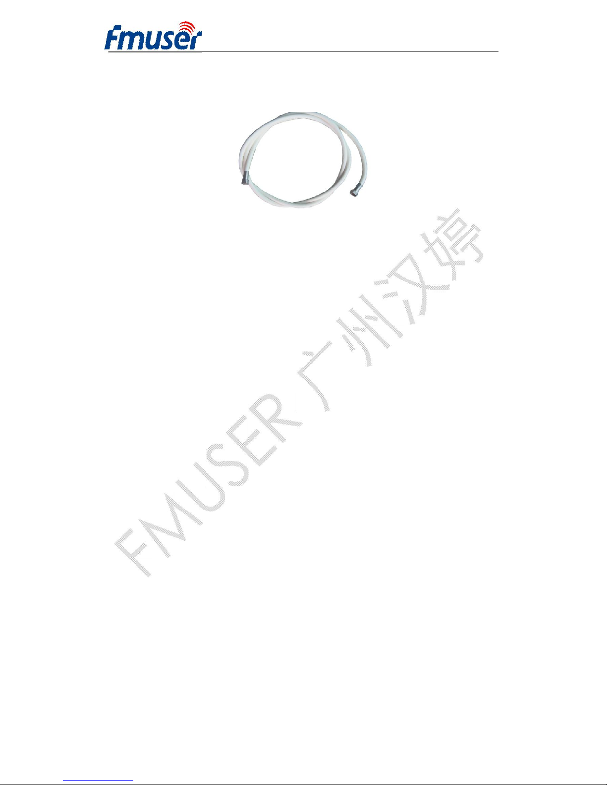
l RF Output Cable Illustration:
Chapter 4 Operation
FUTV4443A 4 in 1 Mux-Scrambling QAM’s front panel is user operation
interface. Before operating, user can decide whether directly use the default
setting or customize the input and output parameters. The detail operations go as
follows:
Keyboard Function Description:
MENU: Canceling presently entered value, resuming previous
Setting; Return to previous menu.
ENTER: Activating the parameters which need modifications, or confirming the
change after modification.
LEFT/RIGHT: To choose and set the parameters.
UP/DOWN: Modifying activated parameter or paging up/down when parameter
is inactivated.
LOCK: Lock the screen / cancel the lock state. After pressing
“LOCK” key, the system will question the users to save present
Setting or not. If not, the LCD will display the current configuration state.
Page 11
FMUSER INTERNATIONAL GROUP INC. 广州市汉婷生物技术开发有限公司
11 / 39
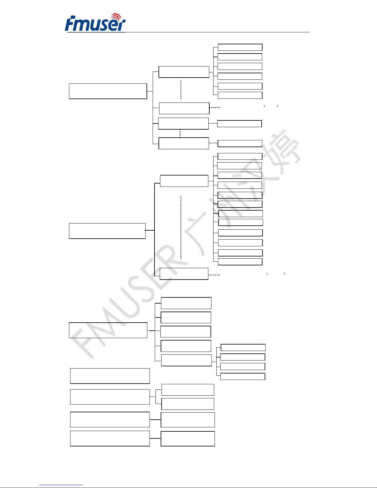
4.1 LCD Menu Tree
Page 12
FMUSER INTERNATIONAL GROUP INC. 广州市汉婷生物技术开发有限公司
12 / 39
4 Network Setting
4.1 IP Address
4.3 Gateway
4.2 Subnet Mask
4.4 MAC Address
4.5 SCR IP Address
SCR IP Address 2
SCR IP Address 3
SCR IP Address 4
SCR IP Address 1
5 Saving Configuration
6 Loading configuration
6.1 Load Saved CFG
6.2 Factory Default
7 Version(SNMP)
SW 0.11 HW 2.1
8 Language
English/中文
3 Output Setting
3.1 Output 1
3.4 Output 4
2 Input Setting
2.1 Port 1
Sat Freq Set
LNB Freq Set
Symbol Rate
2.8 Port 6
LNB Voltage
1.6 22 KHz Switch
Prog Parse
Attenuation
NIT Insertion
Output Stream
Trans Stream
Out Address
Output Carrier
Out IP Enable
Srv Address
Srv Mask
Srv Gateway
Srv Mac Add
Out Port
(Same content with Output 1 )
(Same content with Port 1 )
2.8 Port 7
Prog Parse
2.10 Port 7 Prog Parse
Page 13
FMUSER INTERNATIONAL GROUP INC. 广州市汉婷生物技术开发有限公司
13 / 39
4.2 Main Interface
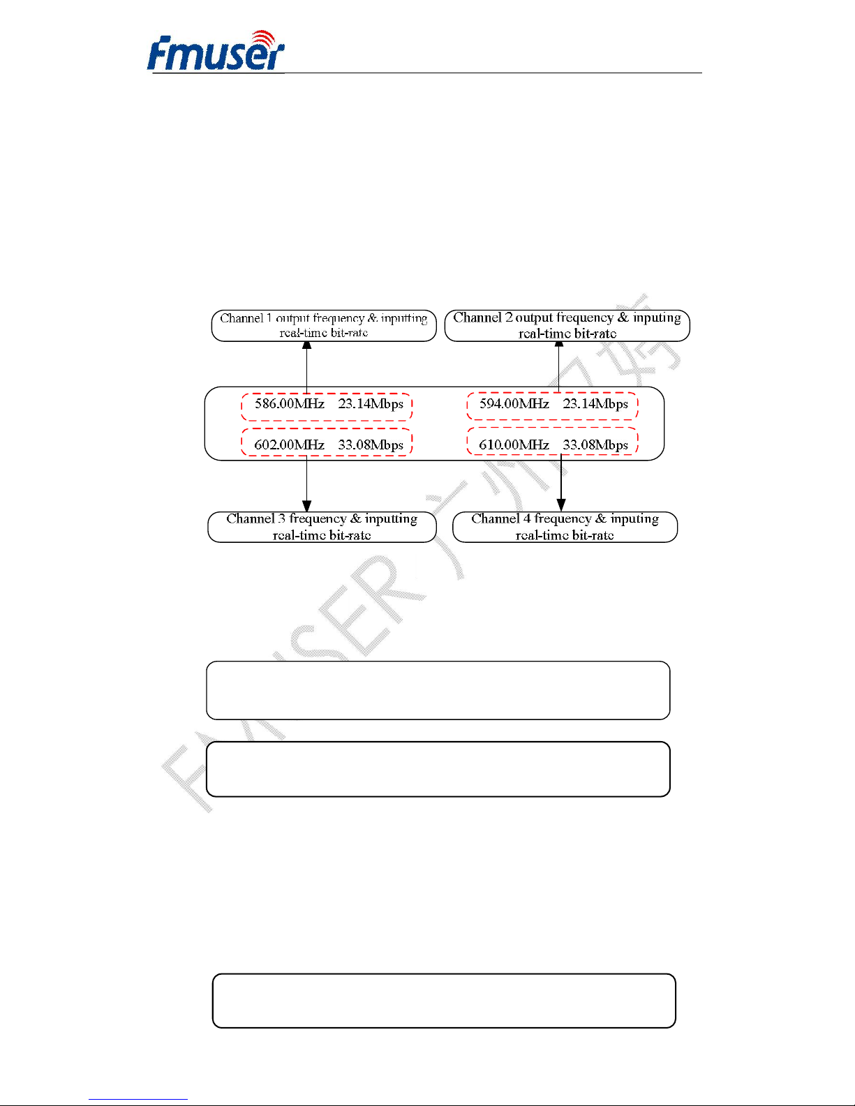
After switching on the Mux-Scrambling QAM, the LCD will display the starting
interface as following page:
Data in the first row is the outputting frequency and inputting real-time bit rate of
channel 1 and channe2, while data in the second row is of channel 3 and channel
4.
4.2.1 General Setting
By pressing “LOCK” key to enter the main menu, the LCD will display the main
menu as the following pages:
By pressing UP/DOWN/LEFT/DOWN key to choose the specified menu item,
then pressing ENTER to enter the submenu.
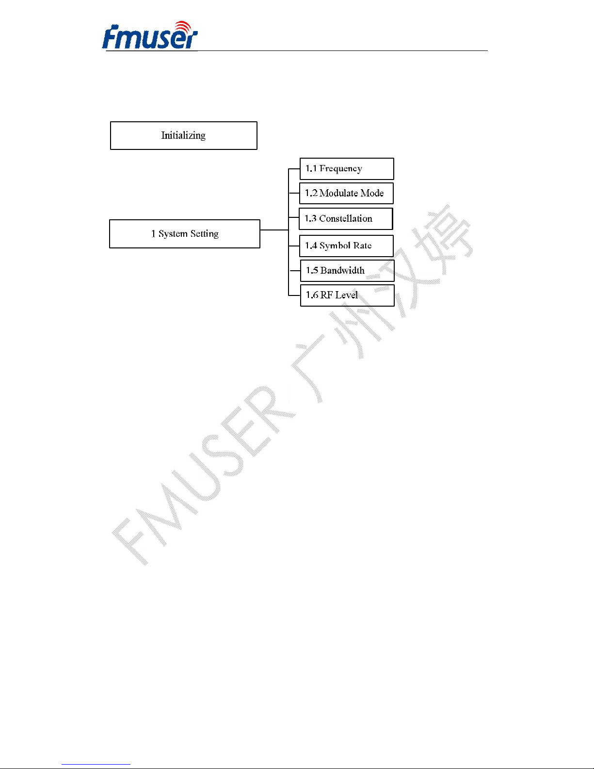
4.2.2 System Setting
User can press ENTER to choose this item, UP/DOWN/LEFT/RIGHT to set the
parameters. The system displays following pages:
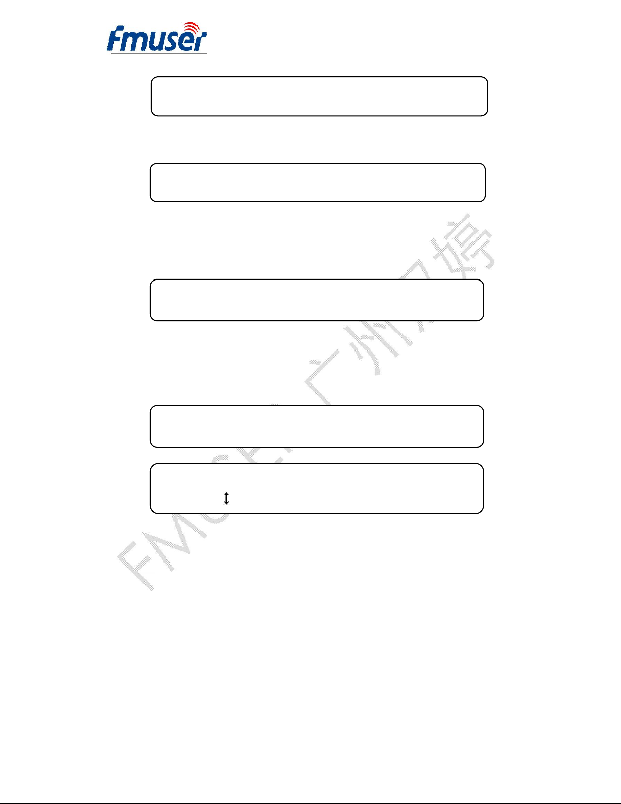
►1 System Setting 2 Input Setting
3 Output Setting 4 Network Setting
►
5 Saving Config 6 Loading Config
7 Version(SNMP) 8 Language
►
1.1 Frequency 1.2 Modulate Mode
1.3 Constellation 1.4 Symbol Rate
Page 14
FMUSER INTERNATIONAL GROUP INC. 广州市汉婷生物技术开发有限公司
14 / 39
4.2.2.1 Frequency
The RF output range is from 48MHz~1000MHz.
4.2.2.2 Modulate Mode
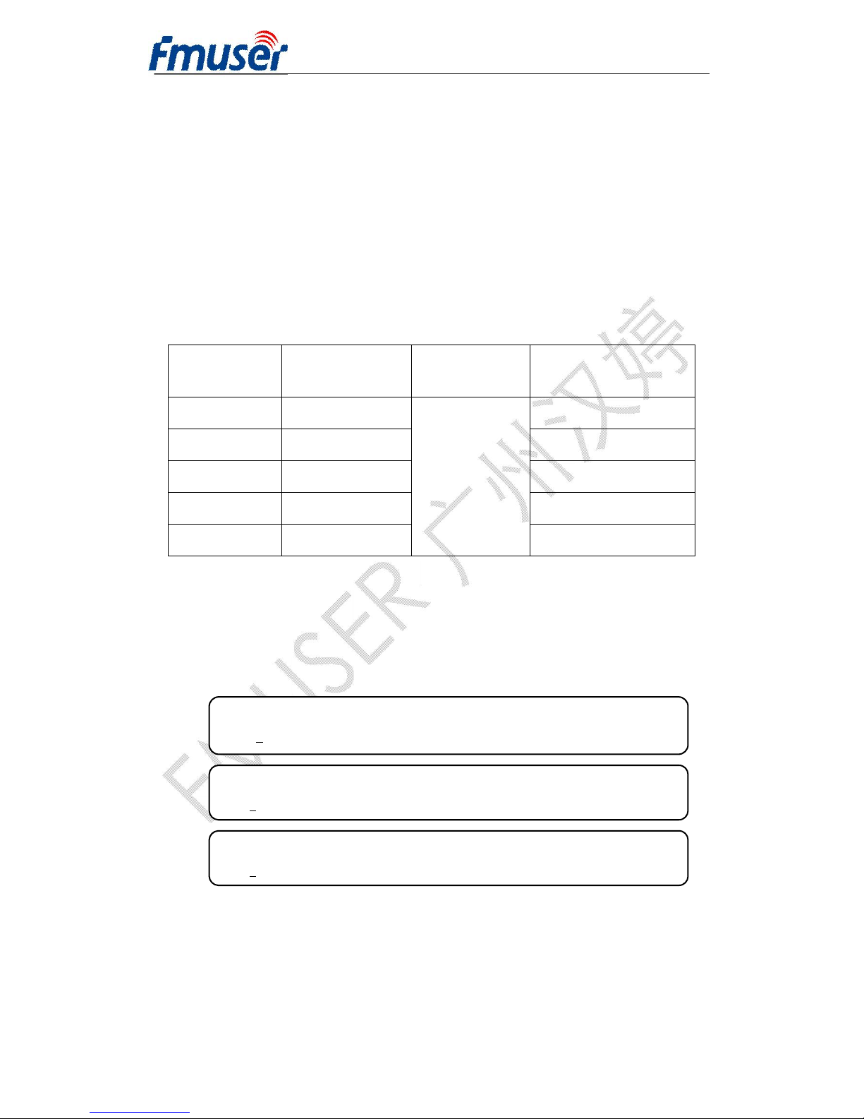
By pressing “1.2 Modulate Mode”, user can choose the standard of QAM
modulation as shown below:
4.2.2.3 Constellation
By pressing “1.3 Constellation” to enter the QAM modulation mode selection,
ENTER to the specified setting. The display shows as below:
Three different constellations: J.83A (DVB-C), J.83B, J.83C will show on the LCD
window when Constellation been entered.
J.83A (DVB-C) contains 16QAM, 32QAM, 64QAM, 128QAM, and 256QAM;
J.83B contains 64QAM, 256QAM;
J.83C contains 64QAM, 256QAM.
Note: The more advanced QAM constellation mode, the higher transmission
efficiency and TS coding rate which the device can transport at the same symbol
rate. Accordingly, with the TS coding rate increasing, the signals’ anti-jamming
capability will become weaker. What needs to be pointed out is, the effective
1.1.1 Frequency
5
86.00 MHz
1.3 Constellation J.83A (DVB-C)
64QAM
1.3 Constellation J.83A (DVB-C)
64QAM
►
1.5 Bandwidth 1.6 RF Level
1.2. Modulate Standard
[J.83A/DVB-C] J.83B J.83C
Page 15
FMUSER INTERNATIONAL GROUP INC. 广州市汉婷生物技术开发有限公司
15 / 39
coding rate this modulator can transport is limitary when the device works as
different constellations and symbol rates.
User can refer to the formula as below:
Max_input_bitrate = Symb_rate*qam_bits*188/204
Max input bit rate: the maximum effective inputting coding rate
Symb rate: the symbol rate
Qam_bits: the QAM bit when device works as current constellation (user can
refer to the following table when device works as 6.875Msps symbol rate):
Constellation
qam_bits
(bit/symb)
Symb_rate
(Msps)
Max_input_bitrate
(Mbps)
16 4
6.875
25.343
32 5 31.679
64 6 38.015
128 7 44.350
256 8 50.686
4.2.2.4 Symbol rate
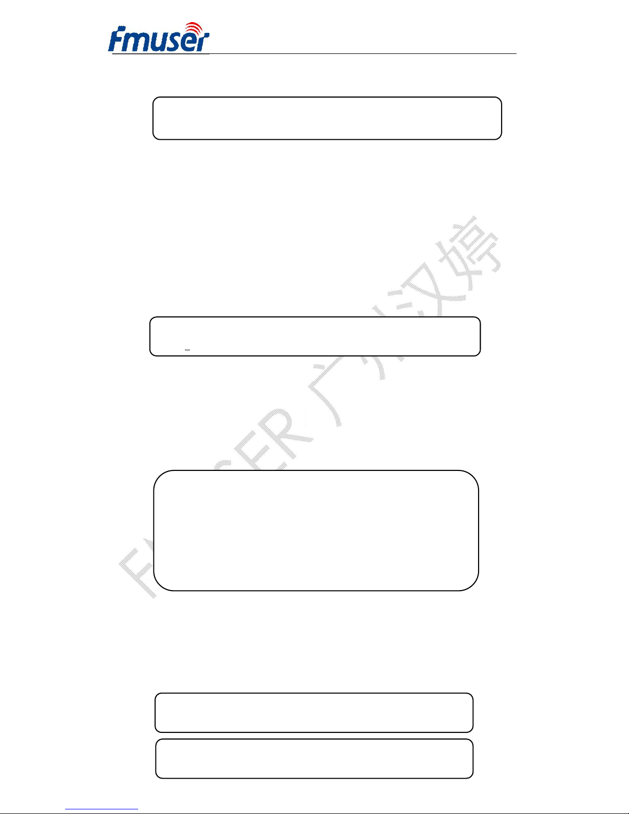
After entering the submenu by pressing ENTER key, user can set the symbol rate
by moving the UP/DOWN/LEFT/RIGHT key and then repressing ENTER to
confirm.
The symbol rate range is 2.5Msps~4.66Msps, 5.0Msps~8.0Msps,1ksps stepping for
J.83A/DVB-C and J.83C.
4.3.2.5 Frequency point bandwidth
After entering the submenu by pressing ENTER key, user can set the bandwidth
►
1.4 Symbol Rate J.83A/DVB-C
6
.875Msps
►
1.4 Symbol Rate J.83B
5
.057Msps
►
1.4 Symbol Rate J.83C
6.875Msps
Page 16
FMUSER INTERNATIONAL GROUP INC. 广州市汉婷生物技术开发有限公司
16 / 39
by moving the LEFT/RIGHT key and then repressing ENTER to confirm.
J.83A (DVB-C) contains 8MHz, 7MHz, 6MHz;
J.83B contains 6MHz;
J.83C contains 6MHz;
4.3.2.6 RF Level Setting
After entering the submenu by pressing ENTER key, user can set the RF Level
by moving the UP/DOWN/LEFT/RIGHT key and then repressing ENTER to
confirm.
The total RF range is from 6 to -25db in 0.5db step.
4.2.3 Input Setting
User can select “Input setting” in the main interface and then press ENETR to
view the inputting ports. The display show as below:
The setting principle is the same for 2.1 to 2.6 turner input port. Hereby we just
take Port 1 as an example to illustrate.
User can choose Port 1 in the submenu by pressing ENTER, and the display
shows as below:
►
1.5 Bandwidth J.83A/DVB-C
*8MHz 7MHz 6MHz
►
1.6 RF Level
+0
0.0 dbm
►
2.1 Port 1(DVB-S2) 2.2 Port 2(DVB-S2)
2.3 Port 3(DVB-S2) 2.4 Port 4(DVB-S2)
: :
: :
: :
2.7 Port 7 (ASI) 2.8 Port 8(ASI)
2.9 Port 7 (ASI) 2.10 Port 8(ASI)
►
2.1.1 Prog Parse
2.1.2 Sat Freq Set
2.1.3 LNB Freq set 2.1.4 Symbol rate
►
2.1.5LNB Voltage
2.1.6 1.6 22KHz Switch
Page 17
FMUSER INTERNATIONAL GROUP INC. 广州市汉婷生物技术开发有限公司
17 / 39
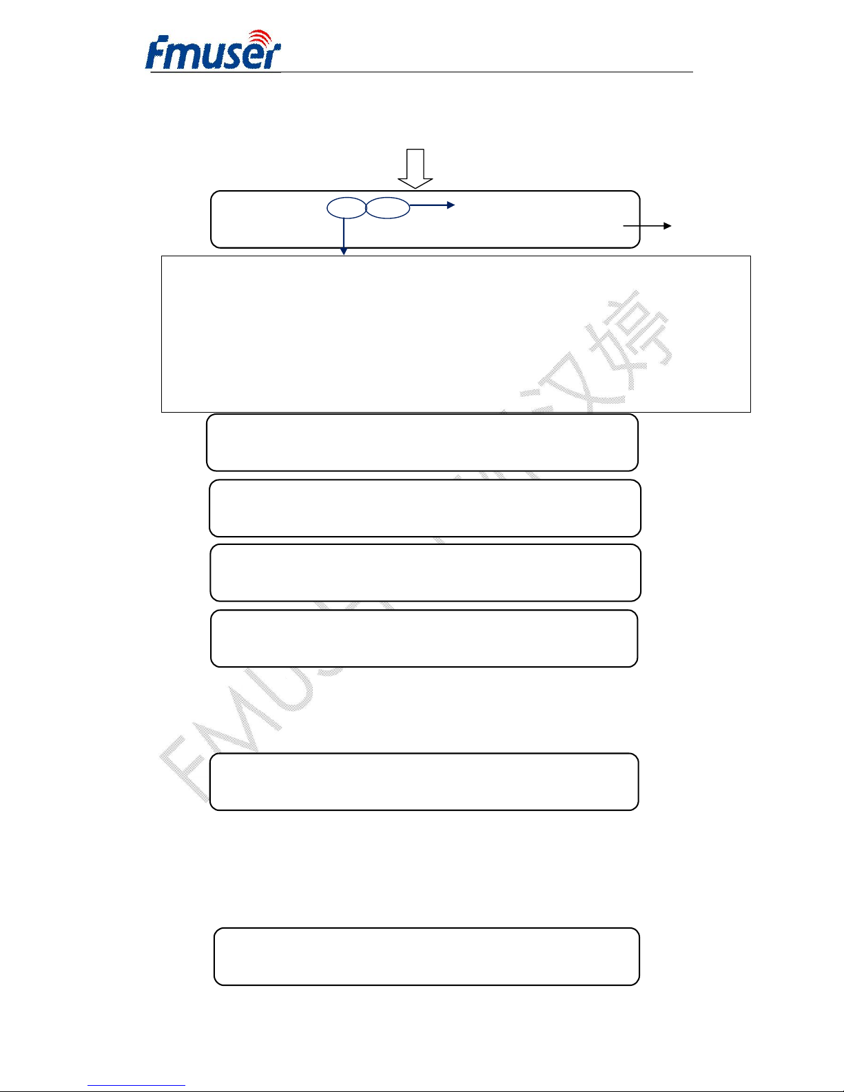
NOTE:
1) When user enters this submenu, user can choose the output program(s) by moving the
UP/DOWN key.
2) Then pressing ENTER to choose the output Carrier(s). Moving the UP/DOWN key
to turn up the mark “※”, which means to output the program from current Carrier.
2.7 to 2.10 are for ASI input port. The
Program Parse
setting principle is the same
as tuner input..
4.2.4 Output Setting
User can select “Output setting” in the main interface and then press ENETR to
set the outputting parameters. The display show as below:
►
3.1 Output 1 3.2 Output 2
3.3 Output 3 3.4 Output 4
►
2.1.1 Prog Parse Port 1 Prog 7
Prog 1 CCTV1 A B C D
Choose Carrier to output
2.1.2 Sat Freq Set
3840 MHz
2.1.3 Symbol Rate
27.500MHz
2.1.4 LNB Voltage
*V (
13V) H(18V) OFF(OV)
2.1.6 22 KHz Switch
*OFF ON
The current Port
The current Port total program number
►
2.7.1 Prog Parse
Page 18
FMUSER INTERNATIONAL GROUP INC. 广州市汉婷生物技术开发有限公司
18 / 39
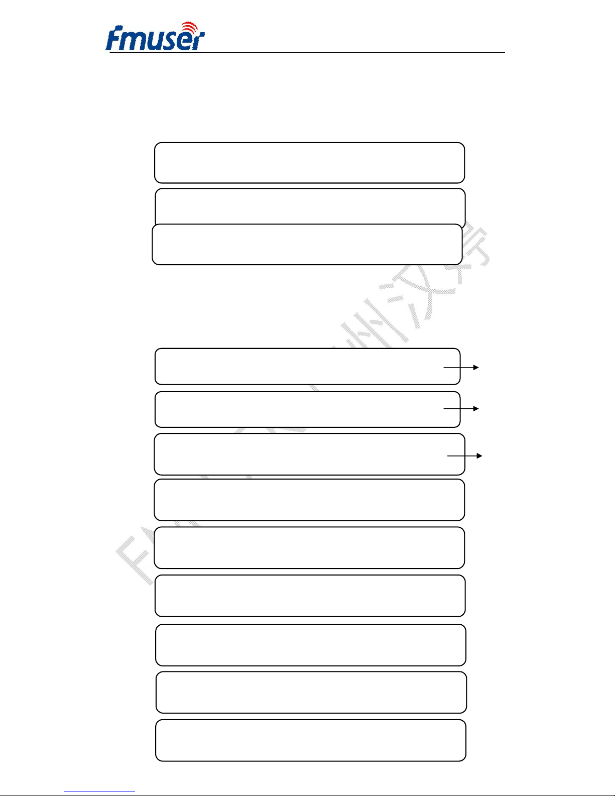
Hereby we just take Output 1 as an example to illustrate.
User can choose output 1 in the submenu by pressing ENTER, and the display
shows as below:
Under the following submenus, there are parameters which can be set manually; user
can press “Up/Down” to choose this item. “Enter” and “Left/Right” to set the
parameters. The system displays following pages.
►
3.1.1 Output Carrier 3.1.2 Attenuation
3.1.3 NIT Insertion 3.1.4 Output Stream
3.1.1 Output Carrier
3.1.2 Attenuation
3.1.3 NIT Insertion
On *Off
►
3.1.5 Trans Stream 3.1.6 Out Address
3.1.7 Out Port 3.1.8 Out IP Enable
►
3.1.9 Srv Address 3.1.10 Srv Mask
3.1.11Srv Gateway 3.1.12 Srv Mac Add
Choose to turn on
the carrier of
output 1’ or not.
Choose to inserted
NIT table or not.
3.1.4 Output Stream
054.000 Mbps
3.1.6 Out Address
224.002.002.003
3.1.7 NIT Insertion
On *Off
3.1.5 Tran stream ID
00000
3.1.8 Out Port
01001
3.1.9 Srv Address
192.168.000.124
Attenuation is from
0~16db in 0.5db step.
Page 19
FMUSER INTERNATIONAL GROUP INC. 广州市汉婷生物技术开发有限公司
19 / 39
The operation of output 2, output 3 and output 4 is the same as output 1.
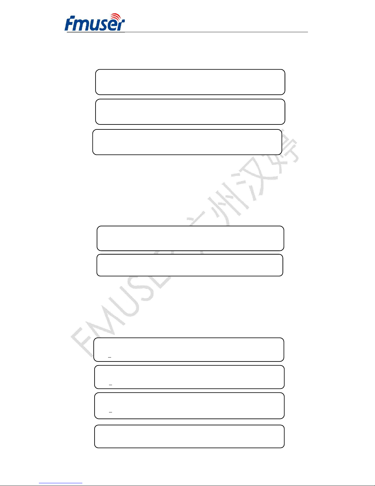
4.2.4 Network Setting
By pressing MENU button on the front panel, user can return to the main
interface and then select item Network Setting by pressing ENTER to set the
parameters. The system displays following pages.
Note: The MAC address is according to the factory setting, and it’s unique.
Under the following submenus, there are parameters which can be set manually; user
can press “Up/Down” to choose this item. “Enter” and “Left/Right” to set the
parameters. The system displays following pages.
4.1 IP Address 4.2 Subnet Mask
4.3 Gateway 4.4 MAC Address
4.5 SCR IP Address
4.1 IP Address
192.168.000.137
4.2 Subnet Mask
255.255.255.000
4.3 Gateway
192.168.000.001
4.4 MAC Address
fffffff
fffffffffffffff
3.1.10 Srv Mask
255.255.255.000
3.1.11 Srv Gateway
192.168.000.001
3.1.12 Srv Mac Add
20141216131
Page 20
FMUSER INTERNATIONAL GROUP INC. 广州市汉婷生物技术开发有限公司
20 / 39
4.2.5 Saving configuration
User can choose to save the current configured parameters by pressing ENTER key.
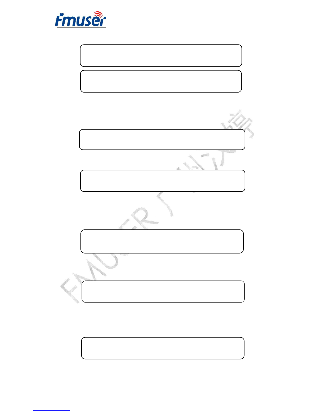
The system displays following page:
4.2.6 Loading configuration
At this menu, press LEFT/RIGHT key and ENTER to confirm.
User can restore the device into the last saved configuration by choosing “6.1” and
restore the device into factory configuration by choosing “6.2”.
When user chooses “6.1” to load saved configuration, the display shows as below:
When user chooses “6.2” to restore the device into factory configuration, the display
will automatically return to the main menu as below:
4.2.7 Version (SNMP)
User can check the hardware version and software version of the equipment.
4.2.8 Language
4.5.1 SCR IP Address 1 4.5.2 SCR IP Address 2
4.5.3 SCR IP Address 3 4.5.4 SCR IP Address 4
Saving, please wait: Writing…….
6.1 Load Saved CFG 6.2 Factory Default
Loading, please wait:
>>>>>>>>>>>>>>>>
SW X.XX HW X.XX
4.5.1 SCR IP Address 1
192.168.002.002
►
1 System Setting 2 Input Setting
3 Output Setting 4 Network Setting
Page 21
FMUSER INTERNATIONAL GROUP INC. 广州市汉婷生物技术开发有限公司
21 / 39
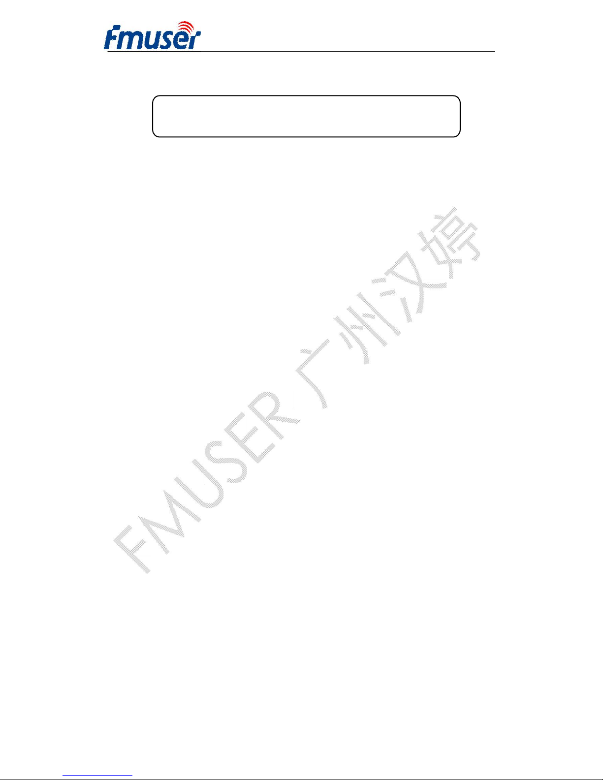
User can select the needed language at this submenu:
Chapter 5 SNMS Setting
Network Management System Profile
Network management system is applied to digital TV equipment operation, control,
management and parameters setting, etc. It centralizes digital TV equipment through
network.
5.1 Installation
The software doesn’t need special installation. User can just copy “Network
Management Software X.XXY.exe” to the specified directory (X.XX is version
number, Y represents language. For example: the version number of network
management software 4.01E.exe is 4.01 English version) or place different versions of
network management software to the same directory. When the network management
software is running, it will generate two documents as follows:
Network management software X.XXY.log (It preserves the log file.)
Info. Bin (It’s the user configuration data.)
5.2 Software Operation
5.2.1 Login Interface
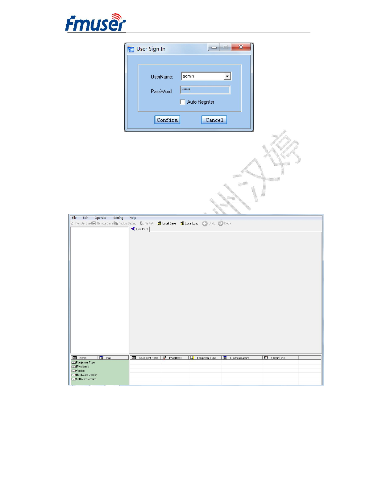
A login interface will pop up firstly when the software is running and give user
prompts to input user name and password, the menu shows as follows:
*English 中文
Page 22
FMUSER INTERNATIONAL GROUP INC. 广州市汉婷生物技术开发有限公司
22 / 39
User can login the NMS by pressing Confirm key after inputting user name and
password. Upon the inputs, the software will verify them with database record
automatically. If both of them are correct, the main interface will appear. Both of the
default user name and password are admin.
5.2.2 Main Interface
User can create a device node tree in the left column by adding, modifying and
deleting the device node. This software provides a powerful node operation function,
and the user can edit various parameters in the device tree for management and
classification.
Page 23
FMUSER INTERNATIONAL GROUP INC. 广州市汉婷生物技术开发有限公司
23 / 39
5.2.3 Adding Frequency Point
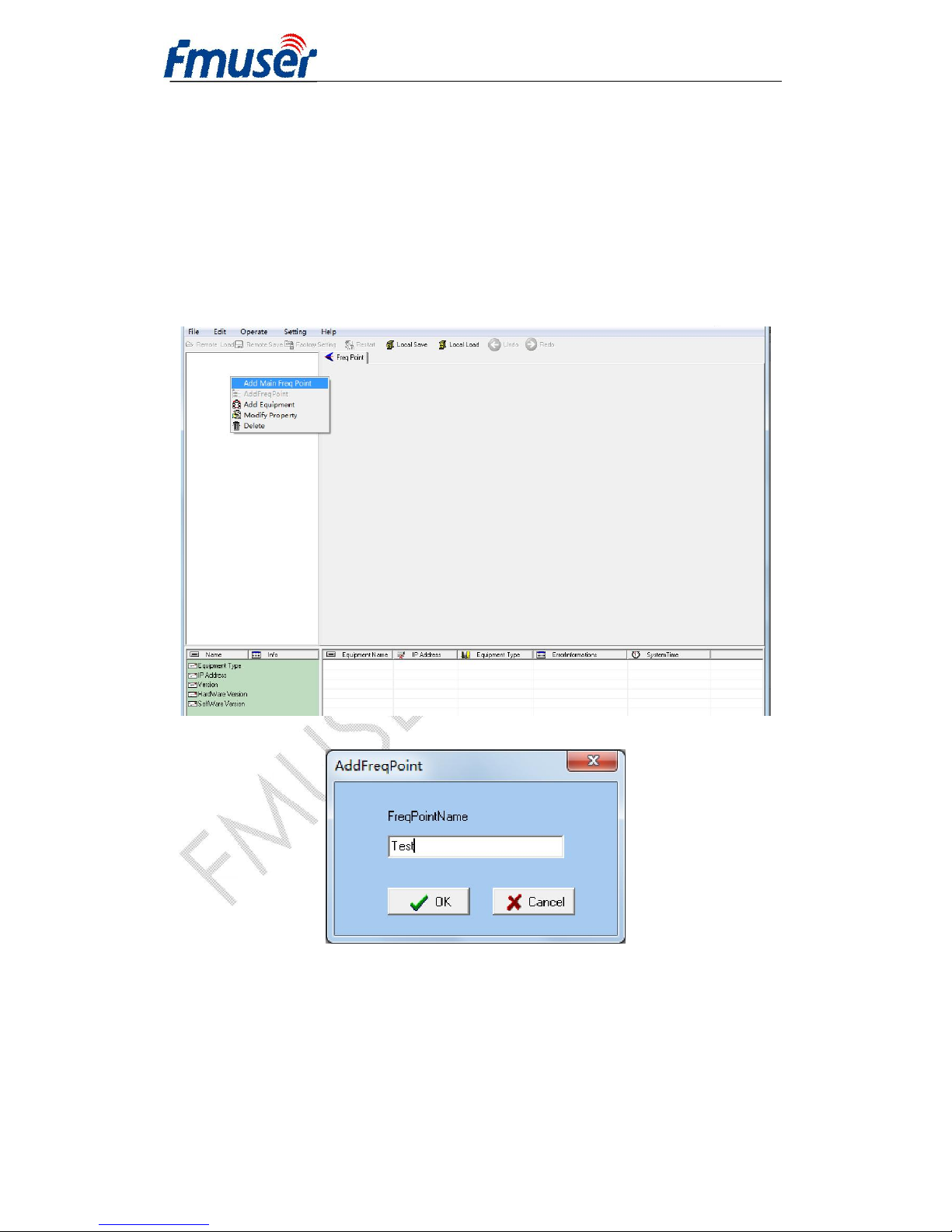
The Add Freq Point dialog box popes up when the user clicks the Add Freq Point
item in the Edit pull down menu on the menu row. User can also click right mouse
key to pop up the short-cut menu in device tree or in the left blank column, then the
Add Freq Point dialog box popes up by choosing Add Main Freq Point. The device
will confirm the given frequency while user clicks OK.
5.2.4 Adding Equipment under Given Frequency Point
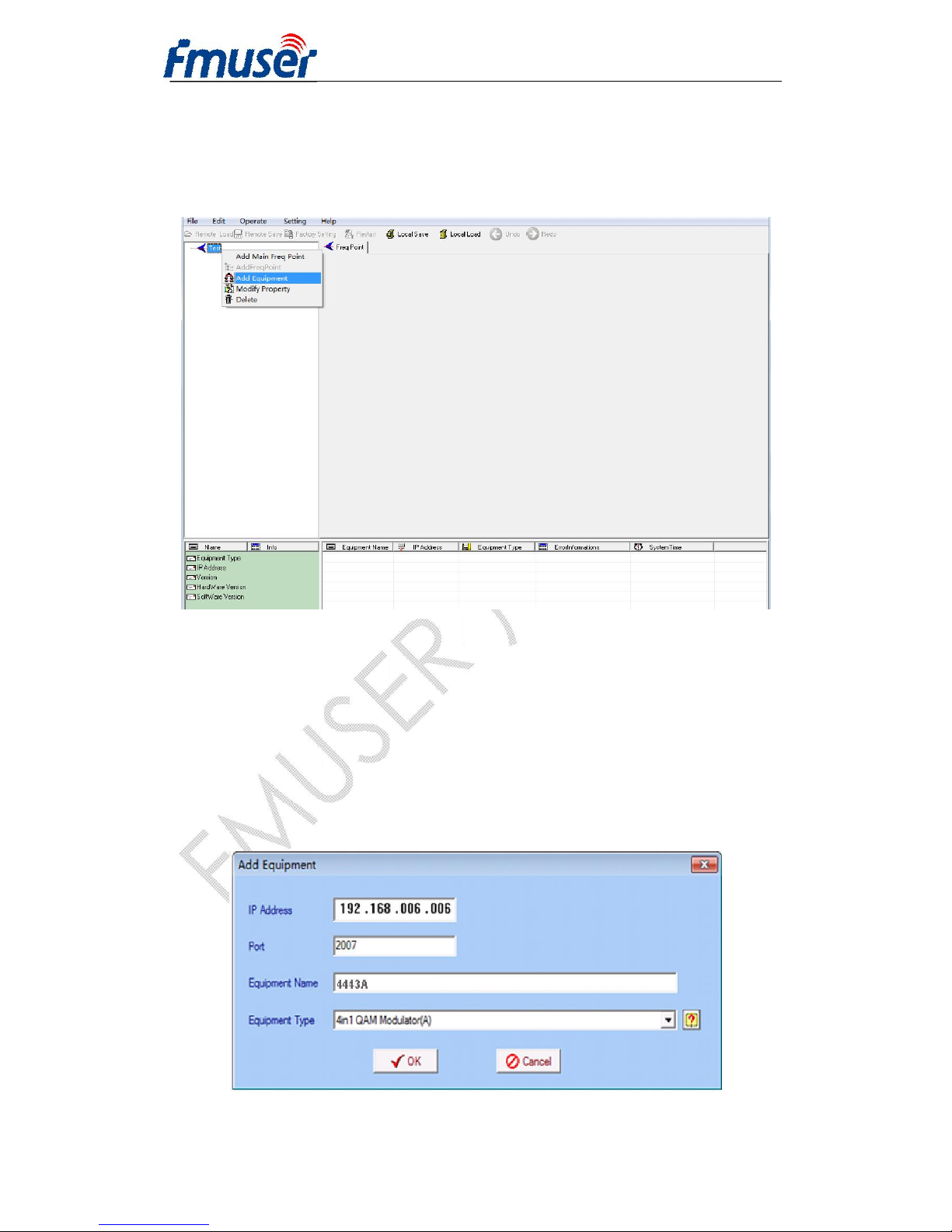
User should choose the frequency point in advance, and then the dialog box of Add
Equipment will pop up when user clicks Add Equipment item in the Edit pull-down
Page 24
FMUSER INTERNATIONAL GROUP INC. 广州市汉婷生物技术开发有限公司
24 / 39
menu on the menu row or clicks right mouse key to pop up the short-cut menu in
device tree or in the left blank column, then the Add Equipment dialog box popes up
by user’s choosing Add Equipment
5.2.5 Edit Equipment Interface
User should follow the steps as below:
l Inputting the device IP Address
l Inputting the device Port Number
l Inputting the Equipment Name
l Choosing the connected equipment type in drop down list of “Equipment Type”
by clicking the “▼” Or Click “?” to auto fine the type of device.
Page 25
FMUSER INTERNATIONAL GROUP INC. 广州市汉婷生物技术开发有限公司
25 / 39
NOTE:
1.
The default IP of FUTV4443A is 192.168.2.1, also you can check its IP address
in the front panel of device in case the IP changed unexpected.
2.
The NMS PC IP address and device IP address should be in the same network.
For example the Device IP is 192.168.2.1. Submask is 255.255.255.0. So the NMS PC
IP address should be 192.168.2.X (1<X<255), submask is 255.255.255.0.
5.2.6 Delete Equipment
User can choose the equipment to be deleted in the left column, and then click the
“delete” item in the pull down menu which appears by clicking the right mouse key.
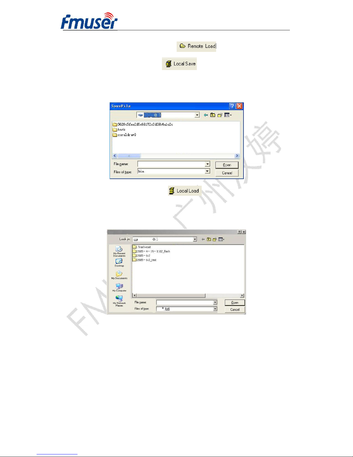
5.2.7 Save Configuration
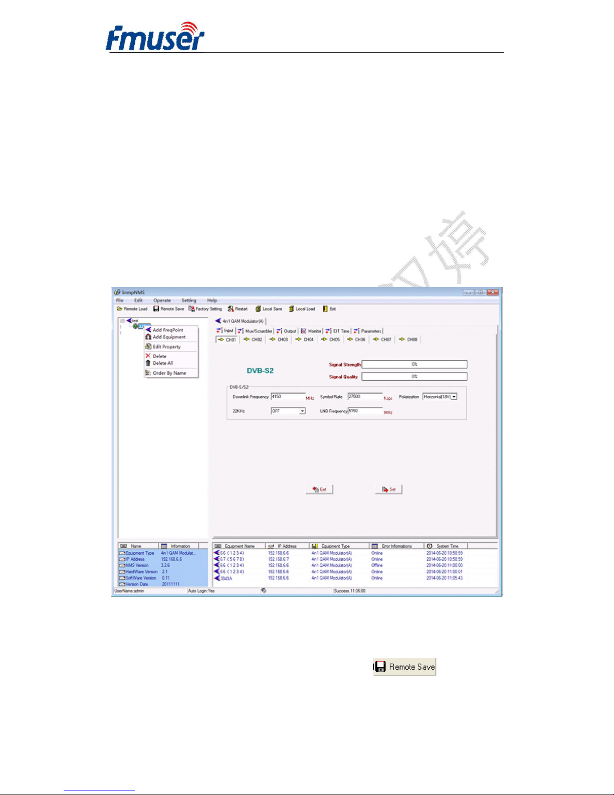
After finishing all the parameters setting, user can click button on the
toolbar to save the modifications to the device’s flash, while user can also reload the
saved parameters from device’s flash and refresh the device’s parameters setting
Page 26
FMUSER INTERNATIONAL GROUP INC. 广州市汉婷生物技术开发有限公司
26 / 39
according to the loaded values by clicking
Alternatively, user can also click the button on the toolbar to popup the
“save file” dialog box, which gives prompts to save all the device’s parameters as
binary files in the computer’s hard disk.
Similarly, user can choose to click the button on the toolbar to popup
the read file dialog box, to read the stored binary file and set the device’s parameters
according to the loaded binary files.
5.3 4443A 4 in 1 Mux-Scrambling QAM Operation
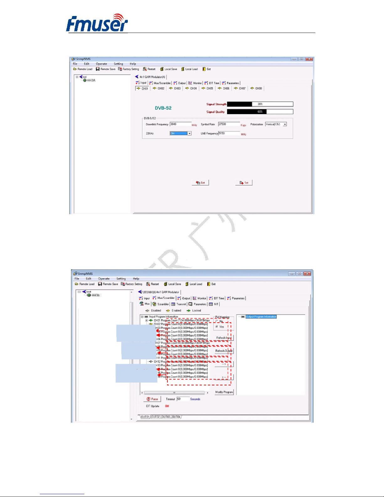
User can choose the “4443A” in the device tree.
Set: making the current parameters, which show in the NMS software, activate.
Get: reading the current device’s activating parameters and show them on NMS
software.
Input setting
Page 27
FMUSER INTERNATIONAL GROUP INC. 广州市汉婷生物技术开发有限公司
27 / 39
User can select “Input setting” in the main interface.
5.3.1 Mux/Scrambler Setting
In this field, users can set and get the device inputting parameters
5.3.1.1 Mux
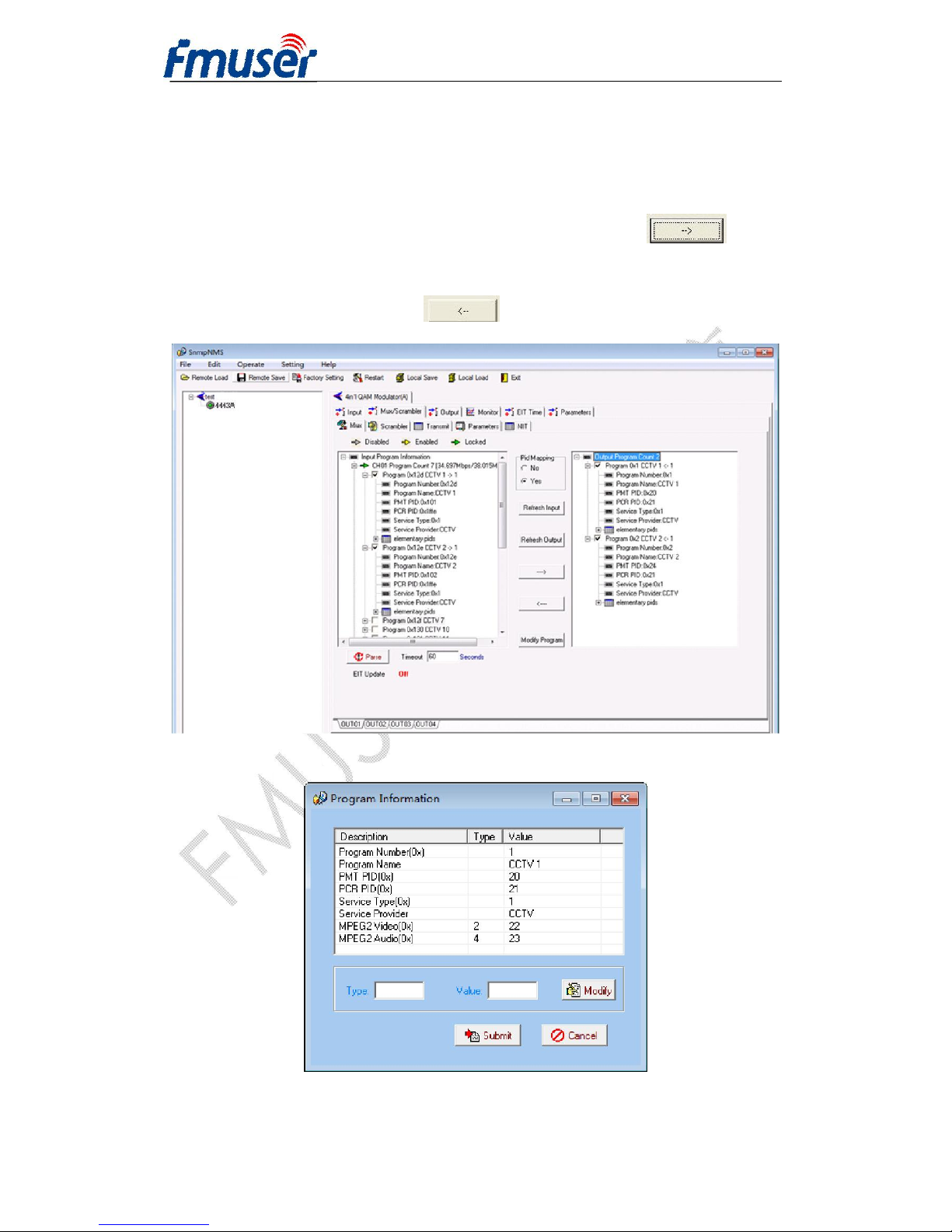
In this box, all 10 inputting ports(6 tuner input and 4 ASI input port) are displayed in
6 Tuner input
4 ASI input
Not applicable
Page 28
FMUSER INTERNATIONAL GROUP INC. 广州市汉婷生物技术开发有限公司
28 / 39
the left box. User can select any port and scan all the programs contained in each port
by clicking PARSE button at the bottom left corner.
Programs refresh input/out
User can select the program to be multiplexd and click the arrow to add
it to the right box, or user can delete the programs which have been multiplexed from
the right box by clicking the arrow
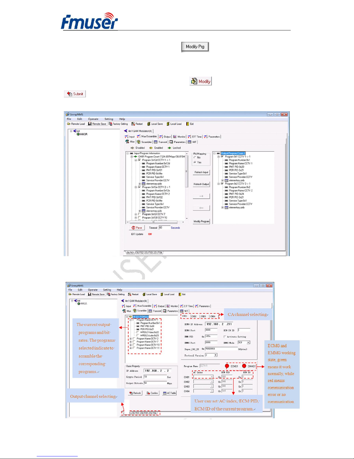
5.3.1.1.3 Program Modification
In case the user intend to customize the details of the programs, user can select the
Page 29
FMUSER INTERNATIONAL GROUP INC. 广州市汉婷生物技术开发有限公司
29 / 39
target program and click Modify Prg button between the 2 boxes, then the
modify interface pops out as shown above. User can select the item to be modified
and input new information in the corresponding box below. To prosper the
modification, pls do click the Modify botton at right and Confirm botton
at left corner. The modified programs are displayed in the right box and an
illustration for reference is as follows:
5.3.1.2 Scrambler Setting
Page 30
FMUSER INTERNATIONAL GROUP INC. 广州市汉婷生物技术开发有限公司
30 / 39
IP Address
This field means the scrambling IP address of the current outputting channels. The
scrambling IP addresses of all modules in the network must be different, and the NMS
IP addresses of all modules must be different. Otherwise, it will cause IP conflict, and
the device will not work normally.
Crypto Period
This field means the scrambling crypto period of the current outputting channels.
After the specified crypto period, the CW will be changed to a new one.
Output Bit-rate
This filed means the TOTAL bit-rate of the current output.
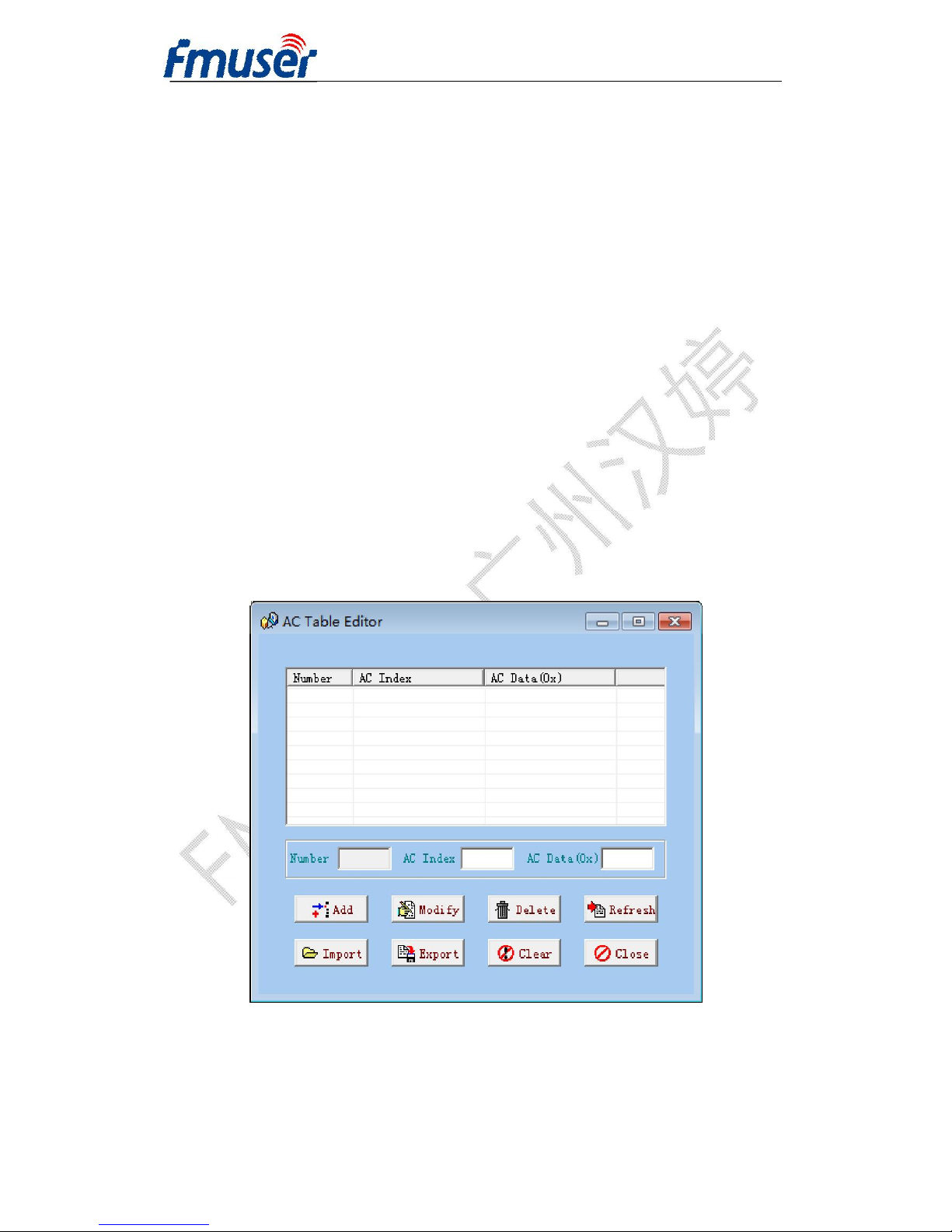
AC Table
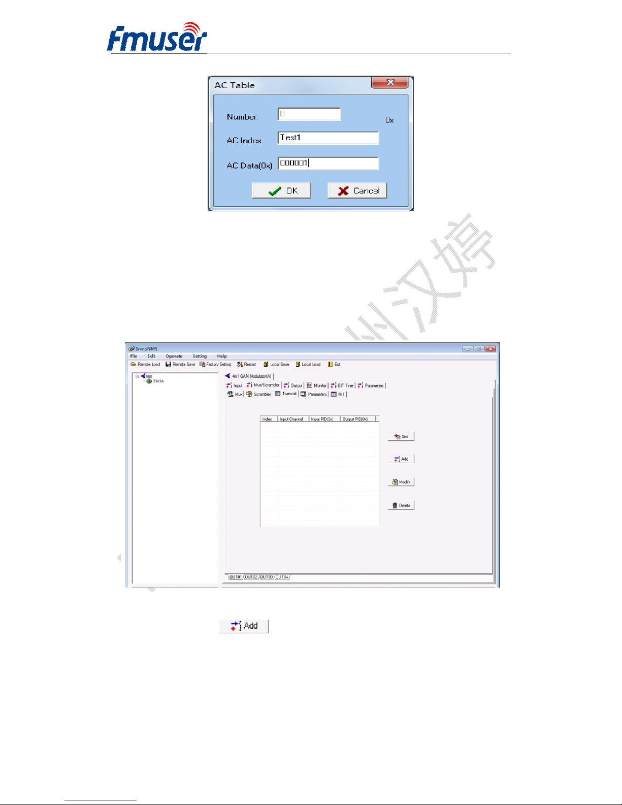
Editing the AC list and then users can add, modify, open and save the AC data. When
clicking it, it will pop up the following interface:
Page 31
FMUSER INTERNATIONAL GROUP INC. 广州市汉婷生物技术开发有限公司
31 / 39
After the modification, users can click the Confirm button to submit the current
configuration, and click the Cancel to quit the current operation.
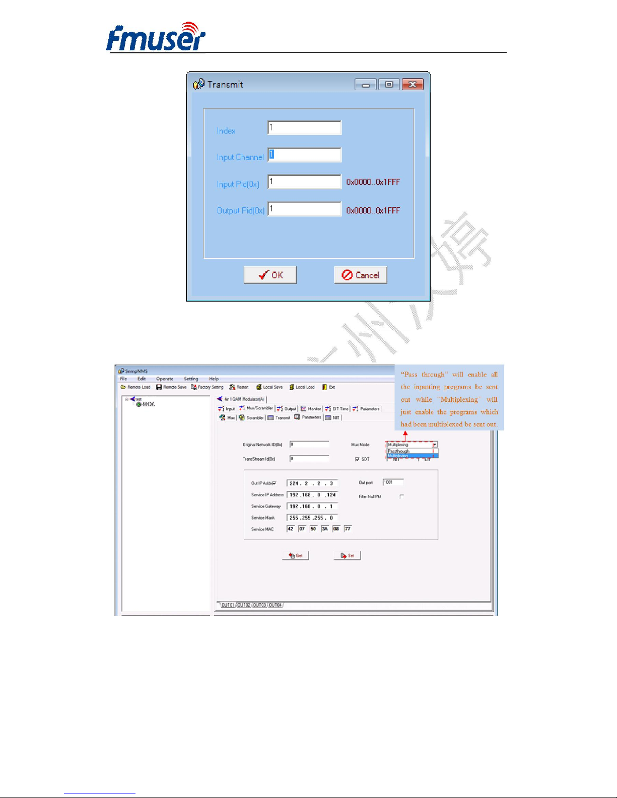
5.3.1.3 Transparent Transport Pass
User can decide to bypass the inputting PID as needed in this interface. This interface
can be used pass through the EPG table, STB update data, etc.
By clicking Add button , the below interface will pop out:
Page 32
FMUSER INTERNATIONAL GROUP INC. 广州市汉婷生物技术开发有限公司
32 / 39
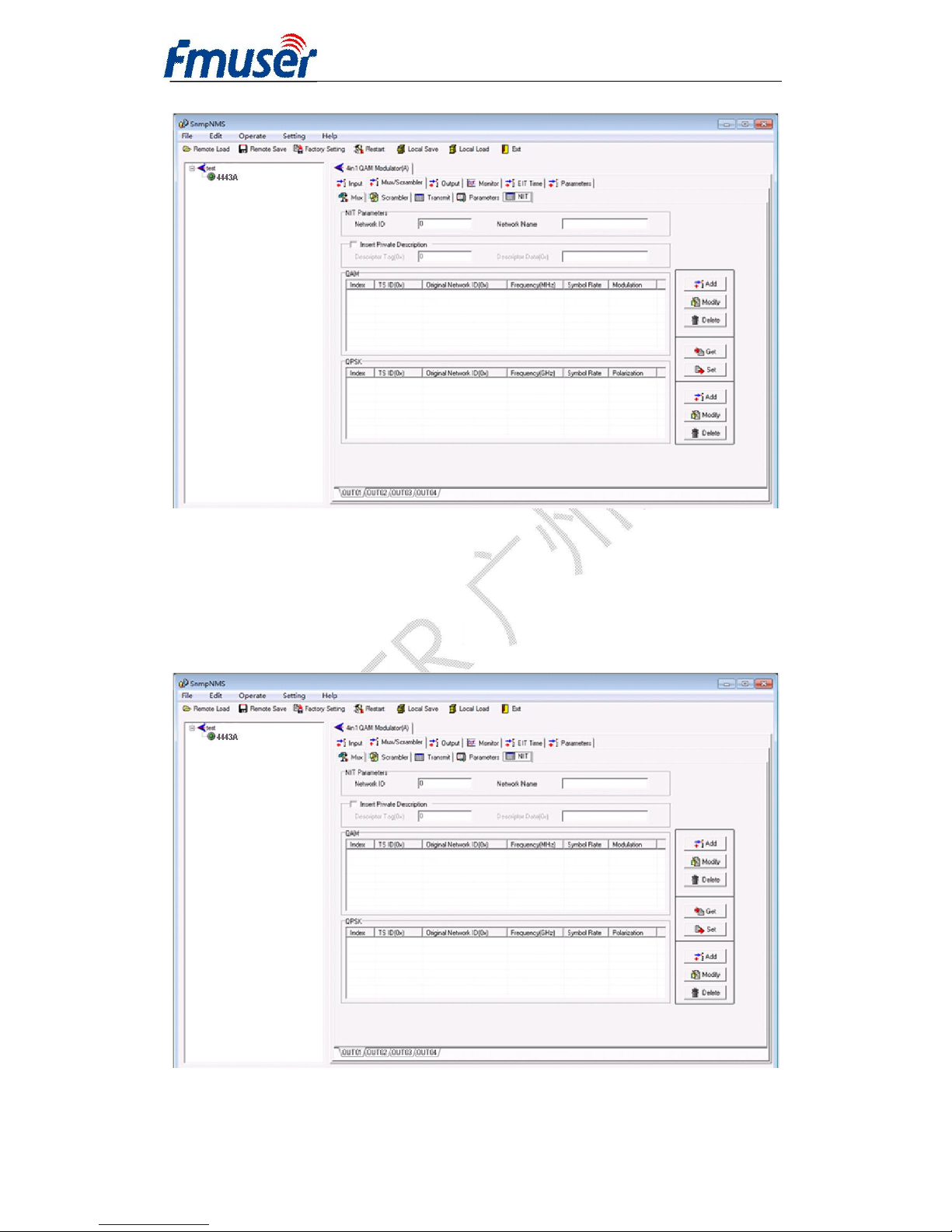
5.3.1.4 Parameters
User can set the output parameters in this interface, the display shows as below.
Page 33
FMUSER INTERNATIONAL GROUP INC. 广州市汉婷生物技术开发有限公司
33 / 39
5.3.1.5 NIT
NIT: Network Information Table.
NIT table is a very important table for describing the network and TS. Users can set
the parameters of the output NIT table as below.
Page 34
FMUSER INTERNATIONAL GROUP INC. 广州市汉婷生物技术开发有限公司
34 / 39
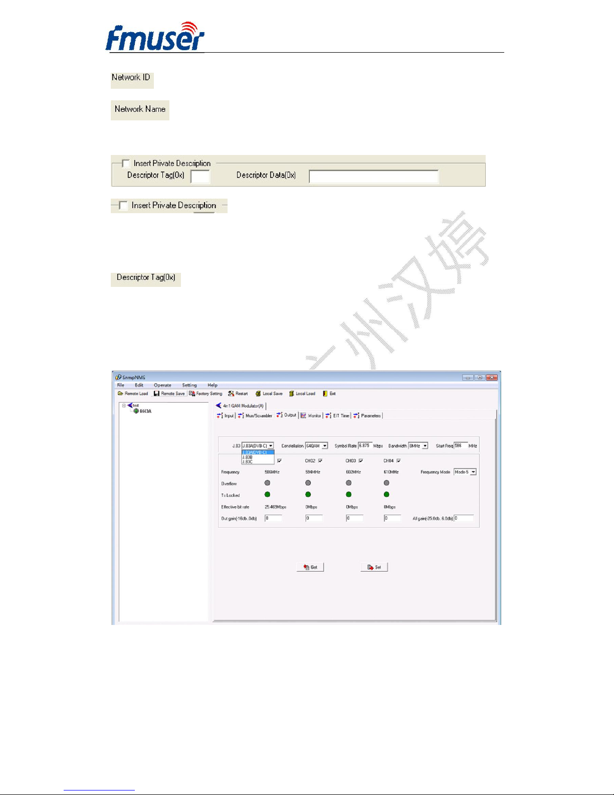
:The parameter describes the output TS’s network ID
:The parameter describes the output TS’s network name
Insertion private description
:This checkbox will allow user to insert the private
descriptor into the output TS. The private descriptor includes two parts. One is
descriptor tag, and the other is descriptor information.
:The descriptor tag is an 8-bit field which identifies each descriptor.
5.4 Out Setting
User can set the parameters of the 4 output QAM carriers (adjacent channels).
Modulation standard: J.83A (DVB-C)
Constellation: 16QAM/32QAM/64QAM/128QAM/256QAM optional
Symbol Rate range: 2.5Msps~4.66Msps, 5.0Msps~8.0Msps,1ksps stepping
Bandwidth:6M/7M/8M optional
Page 35
FMUSER INTERNATIONAL GROUP INC. 广州市汉婷生物技术开发有限公司
35 / 39
Modulation standard: J.83B
Constellation: 64QAM/256QAM optional
Symbol Rate range: 5.057 Msps
Bandwidth:6M optional
Modulation standard: J.83C
Constellation: 64QAM/256QAM optional
Symbol Rate range: 2.5Msps~4.66Msps, 5.0Msps~8.0Msps,1ksps stepping
Bandwidth:6M optional
Out gain: attenuation ranges -25dBm~6dBm,0.5dB stepping
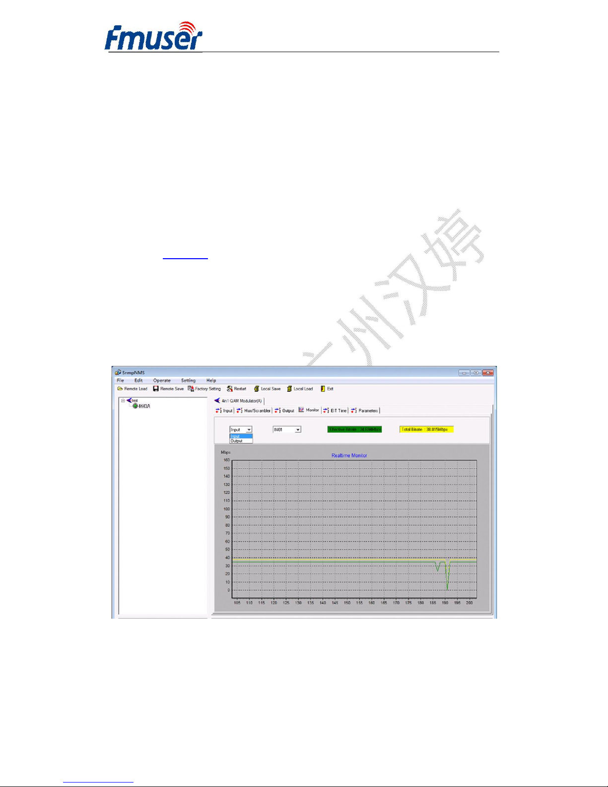
5.5 Real-time Monitor
In this interface, users can monitor the code rate of inputting (256 IP optional) and
outputting (1-8 optional) clearly.
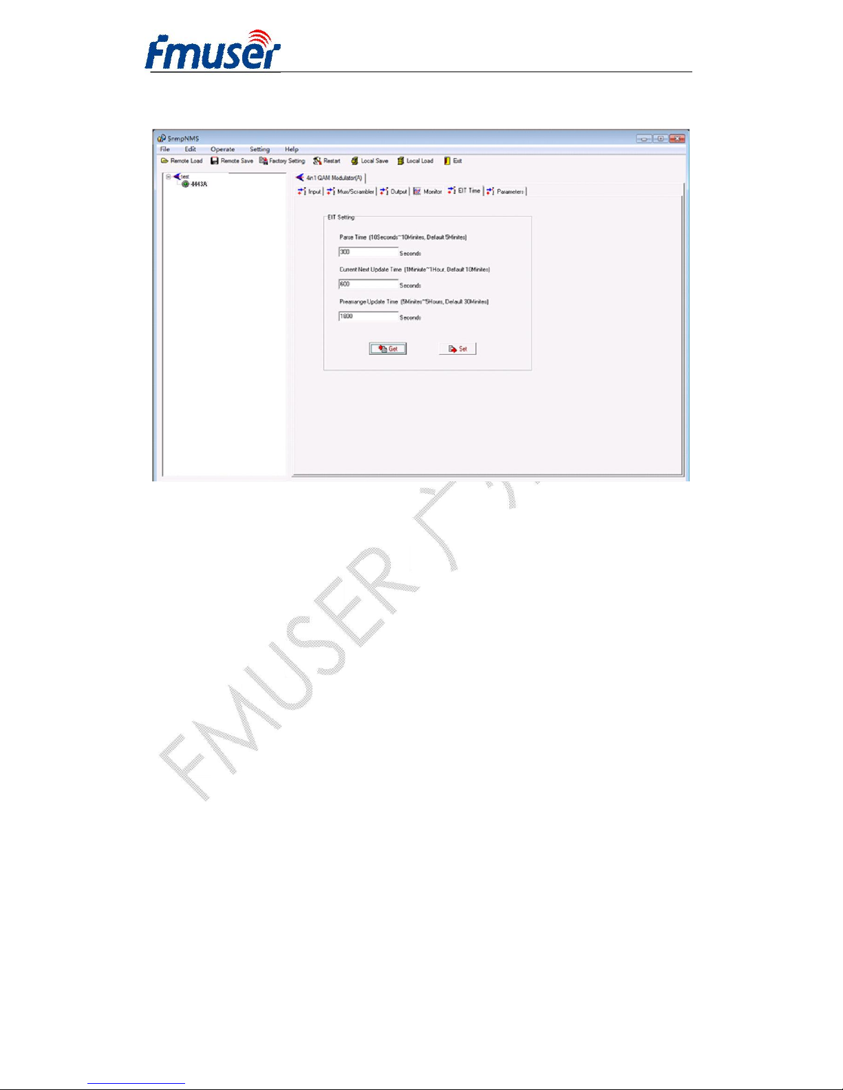
5.6 EIT Time
In this interface, users can set the Parse Time, Current Next Update Time and
Page 36
FMUSER INTERNATIONAL GROUP INC. 广州市汉婷生物技术开发有限公司
36 / 39
Prearrange Update time.
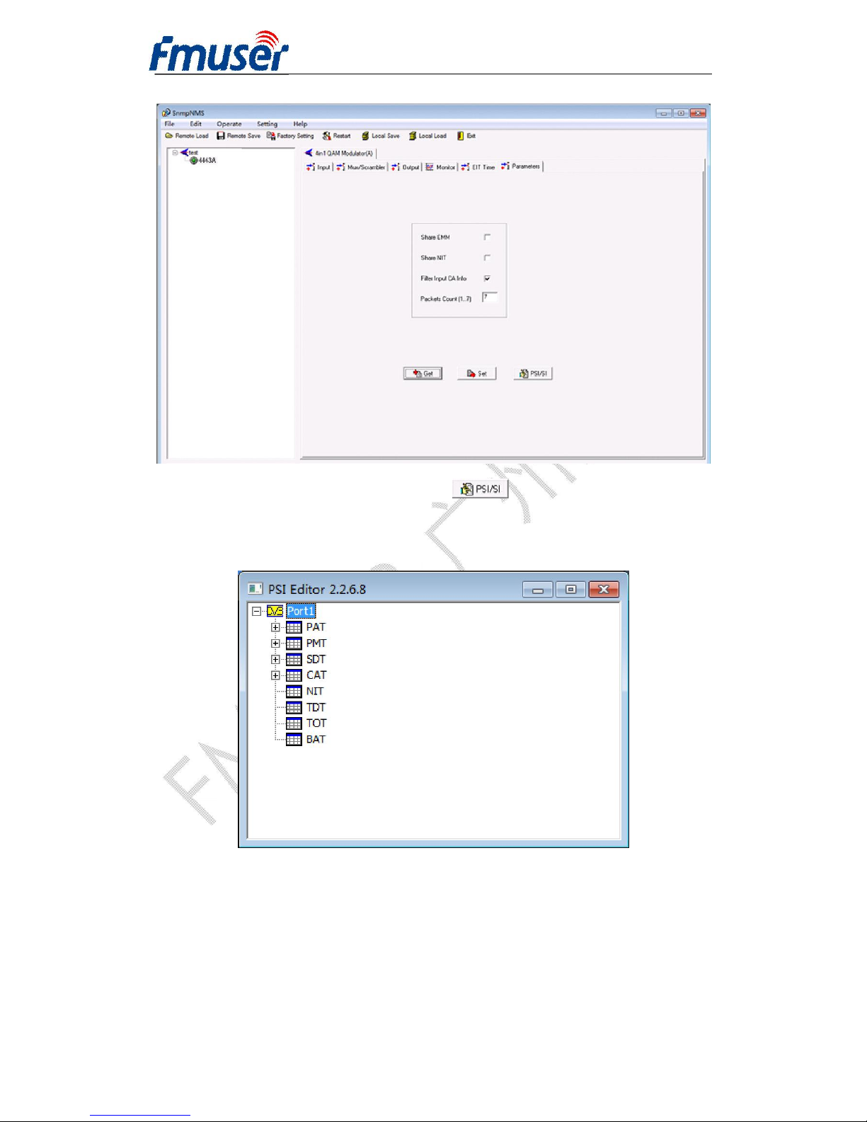
5.7 Parameters
User can set the parameters in this interface, the display shows as below.
Page 37
FMUSER INTERNATIONAL GROUP INC. 广州市汉婷生物技术开发有限公司
37 / 39
User can edit and insert PSI/SI by clicking . It will pop up the following
interface:
Page 38

FMUSER INTERNATIONAL GROUP INC. 广州市汉婷生物技术开发有限公司
38 / 39
Chapter 6 Troubleshooting
This ISO9001 quality assurance system has been approved by CQC organization. For
guarantee the products’ quality, reliability and stability. All our products have been
passed the testing and inspection before ship out factory. The testing and inspection
scheme already covers all the Optical, Electronic and Mechanical criteria which have
been published by our company. To prevent potential hazard, please strictly follow the
operation conditions.
Prevention Measure
l Installing the device at the place in which environment temperature between 0 to
45 °C
l Making sure good ventilation for the heat-sink on the rear panel and other
heat-sink bores if necessary
l Checking the input AC voltage within the power supply working range and the
connection is correct before switching on device
l Checking the RF output level varies within tolerant range if it is necessary
l Checking all signal cables have been properly connected
l Frequently switching on/off device is prohibited; the interval between every
switching on/off must greater than 10 seconds.
Conditions need to unplug power cord
l Power cord or socket damaged.
l Any liquid flowed into device.
l Any stuff causes circuit short
l Device in damp environment
l Device was suffered from physical damage
l Longtime idle.
l After switching on and restoring to factory setting, device still cannot work
properly.
Page 39

FMUSER INTERNATIONAL GROUP INC. 广州市汉婷生物技术开发有限公司
39 / 39
Chapter 7 Packing List
l FUTV4443A 4 IN 1 Mux-Scrambling QAM 1pc
l User’s Manual 1pc
l Tuner wire 5pcs
l ASI wire 4pcs
l Grounding wire 1pc
 Loading...