

Page 1
www.fmuser.org
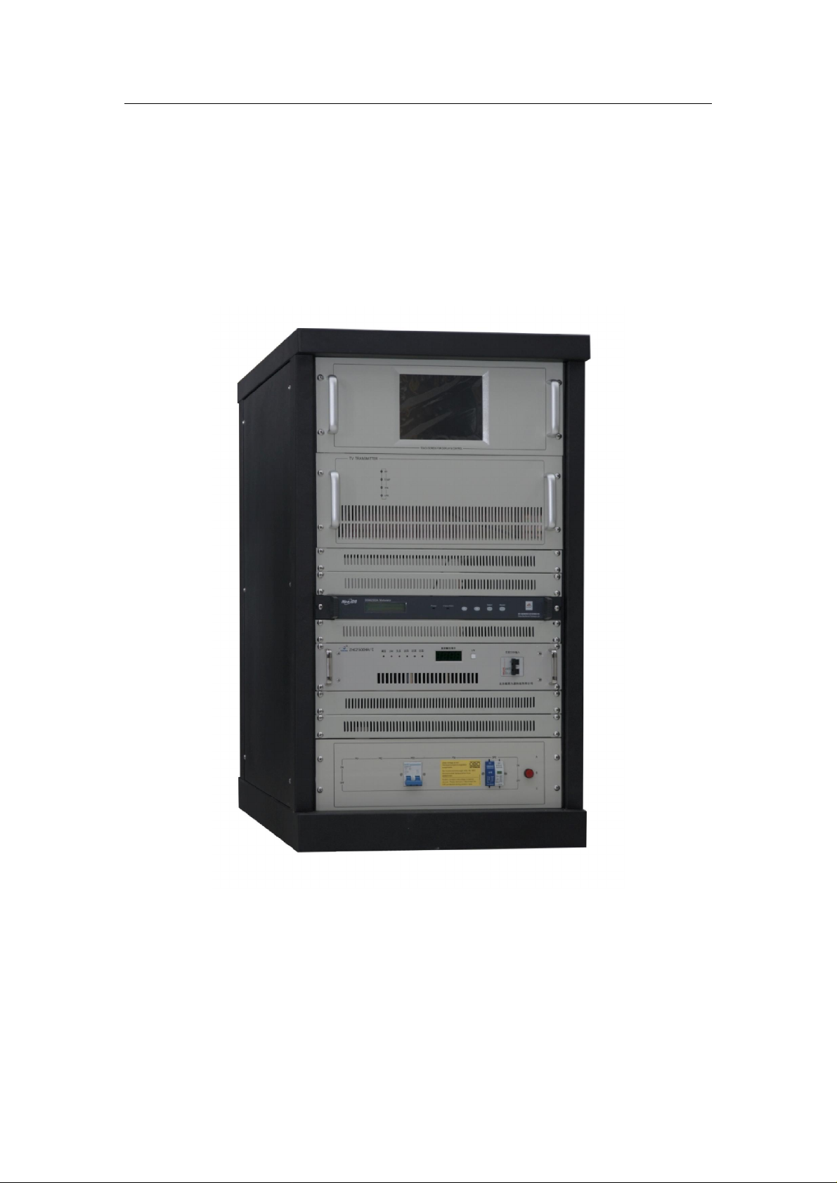
Fmuser.org 500W and 1KW
Analog TV Transmitter
User’s Manual
www.fmuser.org
Page 2

www.fmuser.org
Overview:
This product is the all solid-state Single-channel TV Transmitter, it adopts
professional TV exciter, and it can use the single/duel exciter configuration,
switching automatically.
This transmitter has a variety of linear and non-linear pre-correction function,
carrier frequency offset, and precision bias (with external precision reference
source) function.
It can prefabricate and control the half-power output, and it has remote control
telemetry interface.
The power amplifier used LDMOS FET, the analog and digital are both
compatible, and it used high-quality switch parallel power.
The power amplifier and power supply are both used hot-plug devices.
The power loss and standing wave of the one-time synthesis power combiner is
small.
The module of power amplifier display the working parameters in real-time.
The whole machine has the protection of over-current, over temperature, over
power and over-standing wave ratio.
The master touch screen displays the working parameters of the whole machine
and the module of power amplifier (PA) in real-time.
The 1KW transmitter is installed in one 19inch chassis; it’s suitable for medium
or small TV station.
Features:
● The whole machine is single-channel, image with audio together.
● The redundant configuration design can reduce the rate of inactive to zero.
The exciter redundancy design: the main exciter and its spare exciter can switch
automatically (the spare exciter is optional). When the main exciter broke down,
it can switch to the spare exciter uninterrupted.
The power amplifier redundancy design: multiple amplifiers integrated; the
modules of PA are high-consistency. These two exciters are the spare one with
each other and can exchange easily.
www.fmuser.org
Page 3

www.fmuser.org
The power supply redundancy design: parallel current sharing power from
multiple switching power supply; the computer can monitor power supply’s
working condition and adjust its working condition automatically.
● The management and monitoring are intelligent and on network, it has the
external PC interface.
● It has the technical data detection, monitoring systems and full-featured
computer control software with auto-diagnostic function. All technical
parameters can be read through the LCD display panel.
● Comprehensive protection measures can reduce the damage of equipments.
This machine has protection about no video; VSWR is too large, overheating,
over-stimulus, missing phase protection and lightning protection. The switch has
protection about overvoltage, over current, under voltage, over temperature,
short circuit and lightning protection.
● All power supplies are switching power supplies; high efficiency, excellent
regulator range, strong adaptable from the change of the external voltage.
● It adopts modular design concept.
● Hot-pluggable design: power amplifier and switching power are supporting
the Hot-plug, it’s easy to debug and maintenance; improve the reliability.
● The fan is built-in the chassis, the transmitter has a compact structure and a
beautiful shape.
Technical Specifications:
Overall performances:
1. Working frequency: UHF 13~48 Channel arbitrary choice
2. Output power: 500W/1KW
3. Output impedance: 50Ω
4. VSWR of output load impedance: ≤1.12
5. Inter-modulation distortion: ≤-50dB
6. Useless transmission: In adjacent channel≤-40dB
Out adjacent channel≤-60dB
7. RF output interface: Φ40
8. Power supply: Three-phase 380V Power Consumption
2.5KW
9. Shape size: 1070mm×667mm×955mm
10.Weight: 150KG
Image performance:
1. Video frequency input level: 1V
2. Video frequency input impedance: 75Ω
3. DG: ±5%
4. DP: ±5°
positive polarity
P-P
www.fmuser.org
Page 4

www.fmuser.org
5. Luminance nonlinear: ≤10%
6. Group delay: ≤±60ns
7. Signal-to-clutter ration of low frequency period interference: ≥50dB
Sound performance:
1. Audio input level: 0dBm±6dB
2. Audio input impedance: 10KΩ (imbalance)
600Ω (Balance)
3. Maximum frequency deviation: ±50KHz
4. Harmonic distortion: ≤1%
5. The amplitude frequency characteristics: ±1dB
6. Signal-to -clutter: ≥60dB
www.fmuser.org
Page 5

www.fmuser.org
Please notice this:
1. Read safety notice first。
2. A 50 Ohm dummy load or antenna and cable must be
connected before turning power on, Avoid water going into
the connecters or the cable.
3. Exciter’s operating frequency must be set to the same
frequency of the transmitter.
4. Please read System Control Logic section to understand
how the system works.
5. Setting all parameters before turning on amplifier’s
power (Please read the Power On Sequence section).
www.fmuser.org
Page 6

www.fmuser.org
Contents
Safety Notice-----------------------------------------------------------------4
Special Reminds-------------------------------------------------------------4
1. Power on Sequence ------------------------------------------------------5
2. Control System Introduction ------------------------------------------7
3. Operation Instructions -------------------------------------------------10
www.fmuser.org
Page 7

www.fmuser.org
Safety Notice
1.1 Please read the following safety points, in order to avoid accidents and prevent
connectors to be broken.
1.2 Only the qualified maintenance workers can operate the device.
1.3
P.revent
...
a. Use proper power cord. Other wise, it may cause the fire;
b. Connect the machine to ground through a wire with resistance less than 4
c. Use the proper fuse.
d. Keep good ventilation.
1.4 Please don’t disassemble and repair by yourself when it’s broken down.
............................................................
send to the professional service department to solve the problems.
1.5 Please don’t install the machine in the moisture place;
from
......
Ohm to prevent from electrical shock.
fire and body injury
....
.................
Please
www.fmuser.org
Page 8

www.fmuser.org
Please notice this:
1. The 50Ω dummy load or antenna and cable must be rightly
connected, carefully keep away water into connecters and cable.
2. The design of the transmitter is an integral structure. It gathers the
whole display operation on the LCD display screen, completely
realized the software, the operation is very simple and rapidly. Please
ensure you have read through the following statement about the
software’s use illustration before you turn on the equipment.
Safety Notice
1. Please read the following safety points, in order to avoid the
accidents and prevent the connecting machines to be broken.
2. Only the qualified maintenance workers can operate the service.
3. P.revent the fire and the
...................
e. Use the proper wire. If not, it will cause the fire and the bodily
injury;
f. Ensure the machine connect the ground. Please confirm whether
the machine has connected the ground, through the wire and the
lead, to prevent the electric shock.
bodily injury
............
g. Use the proper fuse. Please use the stipulated type and rating
fuse.
h. Provide good ventilation. This machine adopts the natural
www.fmuser.org
Page 9

www.fmuser.org
convective radiation. Fix it correctly to keep it radiating well.
4. Please don’t disassemble and repair by yourself when it’s broken
5. If you have any other questions, please connect with us.
.......................................................
down.
.....
the problems.
environment;
Please send to the professional service department to solve
CAUTION
Please don’t assemble the machine in the easy
Please don’t repair by yourself.
Please don’t assemble the machine in the moist
:
exploding environment;
www.fmuser.org
Page 10

www.fmuser.org
Overview
This series TV transmitter is an excellent product that owns
the highest and newest technology. The whole machine adopts
the latest TV signal processing technology.
.
www.fmuser.org
Page 11

www.fmuser.org
Display
This series TV transmitter displays the operation parameters of
the modulator on large LCD screen in real time Its particular
FOUR_KEY design, you can conveniently and fast modify,
view the operation parameter and the statement of the
transmitter in any time.
www.fmuser.org
Page 12

www.fmuser.org
Technical Specifications
. Technical Specifications
1. Power Supply □ AC220V±10% 50Hz
□ AC110V±20% 50Hz
□ FULL RANGE
2. Heat Abstraction Forced Convection
3. Output Power: Adjustable Continuous to rate power
4. Output Impedance 50Ω
5. RF Output Linker Standard N-50Ω or 7/16
physical property
1. Temperature Range 5℃~+40℃
2. Relative Humidity <95%
3. Height Above Sea Level <4500m
www.fmuser.org
Page 13
www.fmuser.org
1
3 4
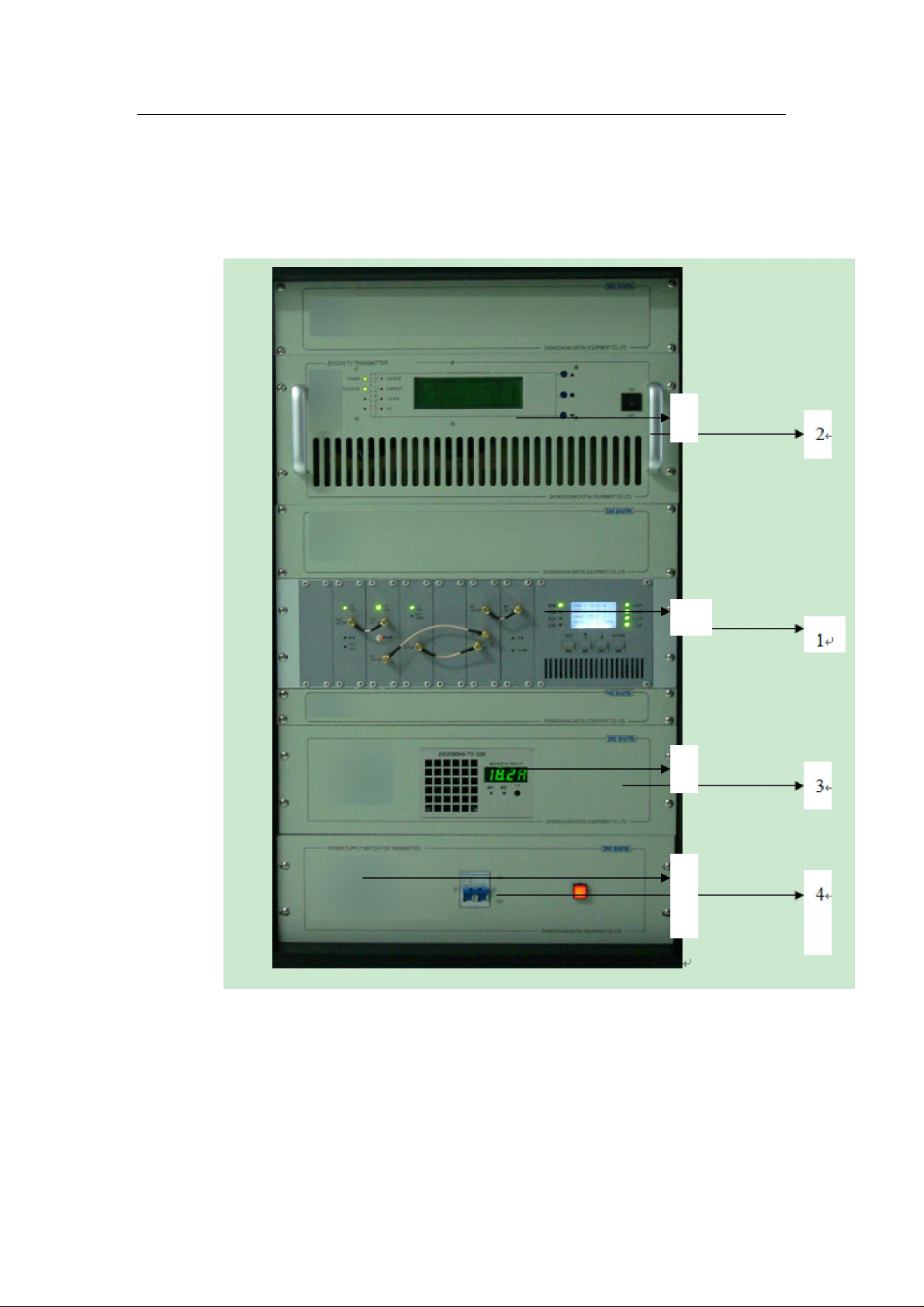
Panel Function Description
I、
Front panel picture
2
1 —Amplifer;
2—MODULATER
3 —SWITCH POWER SUPPLY;
4—POWER SWITCH
www.fmuser.org
Page 14
www.fmuser.org
3
4 5 6
8
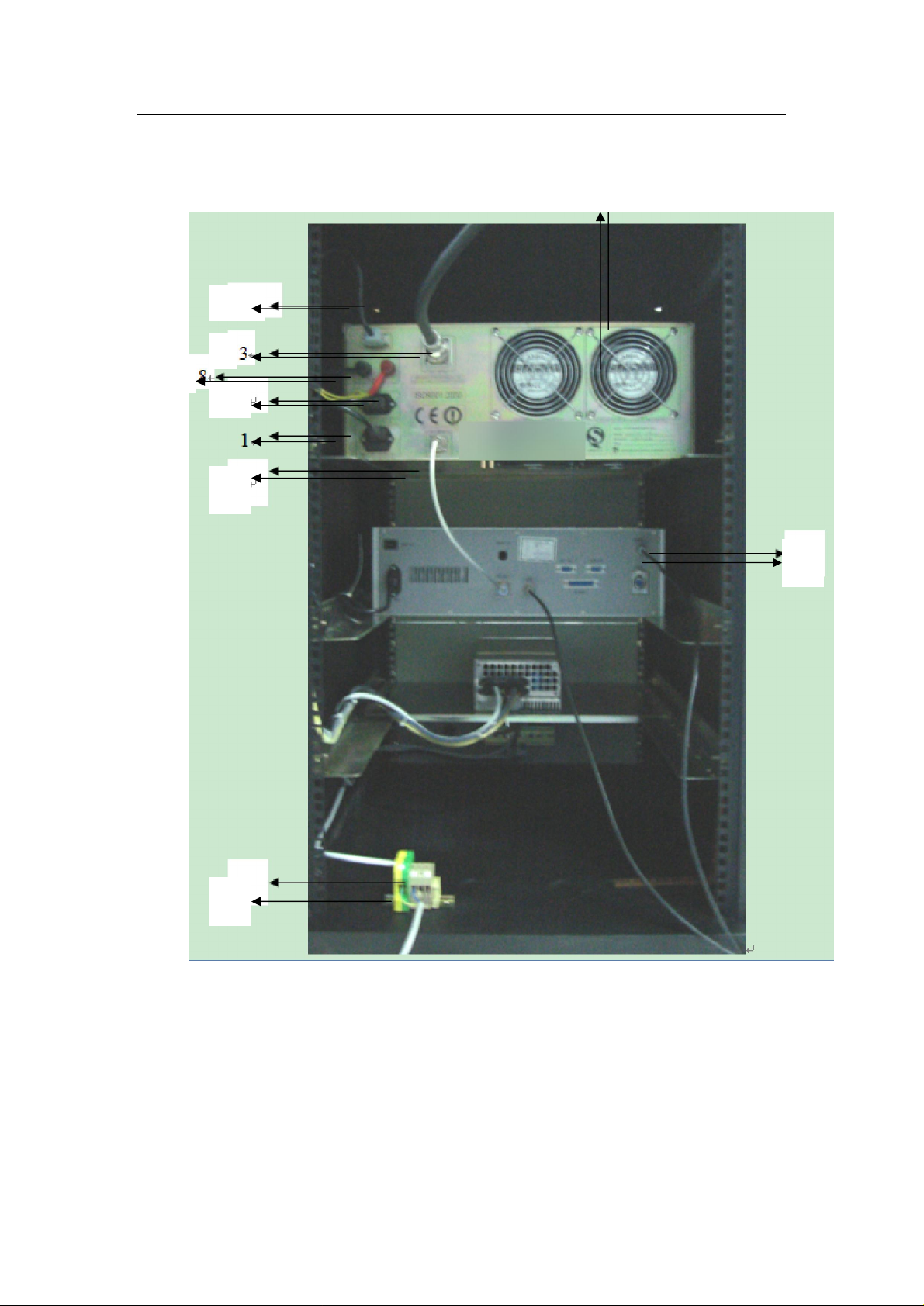
2、REAR panel function description
1
2
1 — AC Socket for amplifer Fuse 5A
2 — RF input Port
3— RF Output Port
4 — AV Input
5 — AC Socket for modulator
www.fmuser.org
Page 15
www.fmuser.org
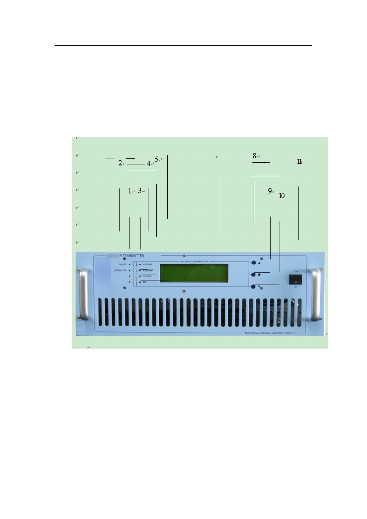
6 — DC controling line
7— AC Connector 220V
8— DC Connector red=”+” black= “-”
2 、PA Front panel function description
1 —POWER: power supply OK;
2—MODULATER: Modulater POWER supply OK
3—VOLTAGE: PA VOLTAGE over alarm;
4—CURRENT: PA Current over alarm;
5—V.S.W.R VSWR is 1.30light, 1.50 transmitter restart。
After restart three times,if the alarm condition do not unchain,
The transmitter will wait for checking.
www.fmuser.org
Page 16

www.fmuser.org
6—RF : RF power over alarm.
7 —LCD display Screen
8 —key-press
UP and LEFT light cursor
9 —key-press
ENTER
10 —key-press
DOWN and RIGHT light cursor
11—Power Switch
www.fmuser.org
Page 17

www.fmuser.org
Special Tips
l Turn on RF power after setting all other parameters
l CAN address of exciters and amplifier modules are set in factory, please do
not change it.
l The transmitter is AGC controlled when CAN AGE in exciter is ENABLED.
l When REMOTE of CCU is enabled, all parameters of CCU can only be
changed remotely.
l RF SWITCH of CCU is a general switch.
l To use period control on CCU, set period first, and then enable PERIOD
CONTROL and finally set RF SWITCH on.
l Always disable exciter’s period control function.
www.fmuser.org
Page 18

www.fmuser.org
1 Power On Sequence
1.1 Check all connections
l Combiner to dummy load or antenna
l Amplifier modules to combiner
l Divider to amplifier modules
l Switcher to divider
l Exciters to switcher
l Main exciter to backup exciter
l Audio to main exciter and backup exciter
l Communication cables
l CCU LOCKOUT to Exciter LOCKIN
l Power cable
1.2 Turn on System Control Power
Check running status in STATUS display page. Make sure all modules are in
normal status.
1.3 Set Exciter Parameters (Produced by this company)
Main and backup exciter parameters setting must be identical!!!
l Frequency: must set to the same frequency as the transmitter allowed.
l Modulation deviation: 75KHz
l Pilot deviation: 7.5KHz
l Audio Input: depends on audio source.
l Audio Gain: adjust audio level according to its input level. Adjusted audio
level should be around 0dBm.
l Power Percentage: 0%
l Period Control: disabled
l Remote Control
“Remote = enabled” for power automatic control.
“Remote = disabled” for power manual control.
l RF Switch: ON
l If other manufacturer’s exciter is used, refer to operation manual they
provided.
www.fmuser.org
Page 19

www.fmuser.org
1.4 Set CCU parameters
l Turn off RF Switch: RF Switch = OFF
l Power Percentage: 0%--100%
l Period Control
If period control is needed, set three periods first and then enable Period
Control (Period Control =Enabled).
If period control is not needed, just disable Period Control (Period Control =
Disabled).
1.5 Turn on the Power Amplifier
l Turn on the Power Supply of the Amplifier PA
l Turn on the RF Switch: RF Switch = ON
1.6 Adjust RF power
l For automatic control, just set power in CCU.
l For manual control, increase exciter’s power slowly; meanwhile watch RF
power and other information displayed on CCU’s LCD.
www.fmuser.org
Page 20

www.fmuser.org
2 System Control Introduction
2.1 Main Control Function
l Data collection and display from 6 amplifiers which include voltage, current,
temperature, running status, forward power and reflect power.
l Combiner data acquisition and display which include temperature, forward power
and reflect power.
l Data collection and display from 2 exciters which include frequency, exciter
working status, forward power and reflect power.
l Amplifier modules and exciters on line detection.
l RF power control and power supply control.
2.2 System Internal Network
Internal network is built through CAN bus. CCU, amplifier modules and exciters are
connected on the CAN bus on which the CCU read information from amplifier
module’s and exciter’s and control the exciter’s power to make the machine’s
Automatic Power Control work.
Each unit on the CAN bus have a unique CAN address and the setting rules are as
below:
Exciter A: 1
Exciter B: 2
Power Amplifier Unit A: 3 (DIP switch)
Power Amplifier Unit B: 4 (DIP switch)
Power Amplifier Unit C: 5 (DIP switch)
……
If there is no corresponding unit or use the other manufacturer’s exciter, the
corresponding CAN address is reserved.
If the exciter breaks off from the CAN bus, the machine’s Automatic Power Control
can not work.
If an amplifier module breaks off from CAN bus, the central control unit will regard
forward power and reflected power of the amplifier as zero. Consequently, CCU
www.fmuser.org
Page 21

www.fmuser.org
unbalance power control strategy will be deployed.
Other manufacturer’s exciter can be used but can not be connected on the internal
CAN bus network not matter there is a CAN interface or not due to the restriction of
the internal communication protocol.
You can confirm if a unit is connected on the CAN bus through the status display
page on CCU’s LCD.
www.fmuser.org
Page 22

www.fmuser.org
2.3 (CCU) Remote Control
CCU has a RS232 interface that can connect to a computer for the remote control
purpose. The remote computer can read the following datum:
l Equipments’ type and profile, such as nominal power, frequency, number of
amplifier modules, maximum power of amplifier module and number of exciters.
l Machine’s forward power; reflect power; temperature and other working status.
l Exciter’s operating frequency; forward power; reflect power and other working
status.
l Each amplifier unit’s forward power; reflect power; temperature; voltage; current
and other working status.
The remote computer can do following controls:
l RF Switch
l Setting Power
We can provide software (not free) running on WINDOWS operating system for
remote control; and also provide protocol in order for customer to embed our system
in their remote control system.
Our company’s exciter can also be individually controlled remotely, but we
strongly recommend using the remote control interface of CCU as the only remote
control interface.
If other manufacturers’ exciter is used, remote system can not read the related
information of the exciter through the CCU.
CCU’s parameters can not be changed locally when remote control is enabled
(refer to remote page operation).
2.4 Automatic Power Control & Manual Power Control
Automatic Power Control means to maintain a constant transmission power under
normal working condition. In abnormal working condition, CCU tries to keep the
output power as high as possible but the first thing is to keep the transmitter in safety
condition.
Only with ZHC’s exciter, the Automatic Power Control function is able to work.
www.fmuser.org
Page 23

www.fmuser.org
The Automatic Power Control function is enabled when exciter’s CAN AGC is
set to enabled, otherwise the system is in Manual Power Control mode.
In manual power control mode, the output power is not controlled by CCU (CCU
can not control exciter’s power). So, the machine’s output power would be fluctuated
with the temperature or other factors change. In the abnormal working condition, the
system will not automatically reduce its output power because the exciter’s power is
out of control in manual control mode. In extreme case, the system will powered-off
for protection.
2.5 RF Output Control
2.5.1 CCU RF Switch
l When RF Switch is off, turn off RF power and power supply.
l When RF Switch is on and Period Control is disabled, turn RF power on to
setting power.
l When RF Switch is on and Period Control is enabled, RF power is controlled by
Period Control function (see Period Control).
2.5.2 CCU Period Control
When RF Switch is on and Period Control is enabled, the control method is as
follows:
The system reads current time through RTC and check whether current time is
falling into any of the three periods. If yes, turn on RF power to its period setting
power, else turn off RF power. A period is invalid if start time is greater than or equal
to end time. Invalid time period is ignored in Period Control (Current time will never
fall into an invalid period). If three periods are all invalid, turn RF power off for ever.
Invalid period is useful when only one or two period is needed.
It is suggested that disable Period Control before correcting date and time or
changing period’s start and end time to avoid instantaneous undesired RF Switch on
and off.
www.fmuser.org
Page 24

www.fmuser.org
2.6 System Protection
AIn automatic control mode, if RF output power is not able to reach to setting
power, it may cause by:
l Combiner temperature is above 70.
l Combiner’s reflect power is above the warning value (more than 2% of the
machine’s nominal power).
l Unbalance power (the power difference between the maximum output power
and minimum output power from all the power amplify modules) above the
warning value (more than 25% of Power Amplifier’s nominal power).
l Power of individual amplifier module above the warning value (more than
2% of Power Amplifier’s nominal power).
l One or more amplifier module is not on line.
AIn automatic and manual control mode, if RF output power reboot, it may
cause by:
l Combiner temperature is above 85.
l Output power is too high (more than 5% of the machine’s nominal power).
l Reflected power is too high (more than 4% of the machine’s nominal power)
l Unbalance power is too high (more than 30% of the power amplifier’s
nominal power).
l Power of individual is too high (more than 5% of the power amplifier’s
nominal power).
AIn automatic and manual control mode, if RF output power can not reboot
again, it may cause by:
l Three times failure of power reboot in 10 minutes.
l Other hardware reasons.
AThe only way to run the system properly again is to turn off system control
power and amplifier’s power, and then turn on again.
www.fmuser.org
Page 25
www.fmuser.org
3 CCU Menu Operation
3.1 General Descriptions
The CCU LCD display is divided into 4 functional pages: Main Page, Status Page,
Time Page and Remote Page. Touch screen is used to get through all functions.
Three hidden buttons is used to set and select parameters. When click on the
displayed setting parameter, buttons are visible and setting parameter is displayed in
reverse video indicating the parameter is in editing. Use UP and DOWN
button to change parameter and ENTER to confirm and save it. Click any other
area to cancel current editing and restore its old parameter value.
When click on display only item or title or any empty area, buttons are not visible
and the system does nothing. So, distinguish whether the parameter is a setting
parameter first. But not worry about this, because you can try to click anywhere on
the LCD and setting parameters are also specified bellow in each page.
UP or increase, when press and hold for a longer time, it speeds up.
It’s very useful when using it to change wide range parameters.
ENTER, Confirm and Save edited parameter.
DOWN or decrease, when press and hold for a longer time, it speeds up.
www.fmuser.org
Page 26
www.fmuser.org
3.2 System Boot up
During the system boot up, company logo is displayed until system boot up finish.
After system booting up, it enters to Main Page.
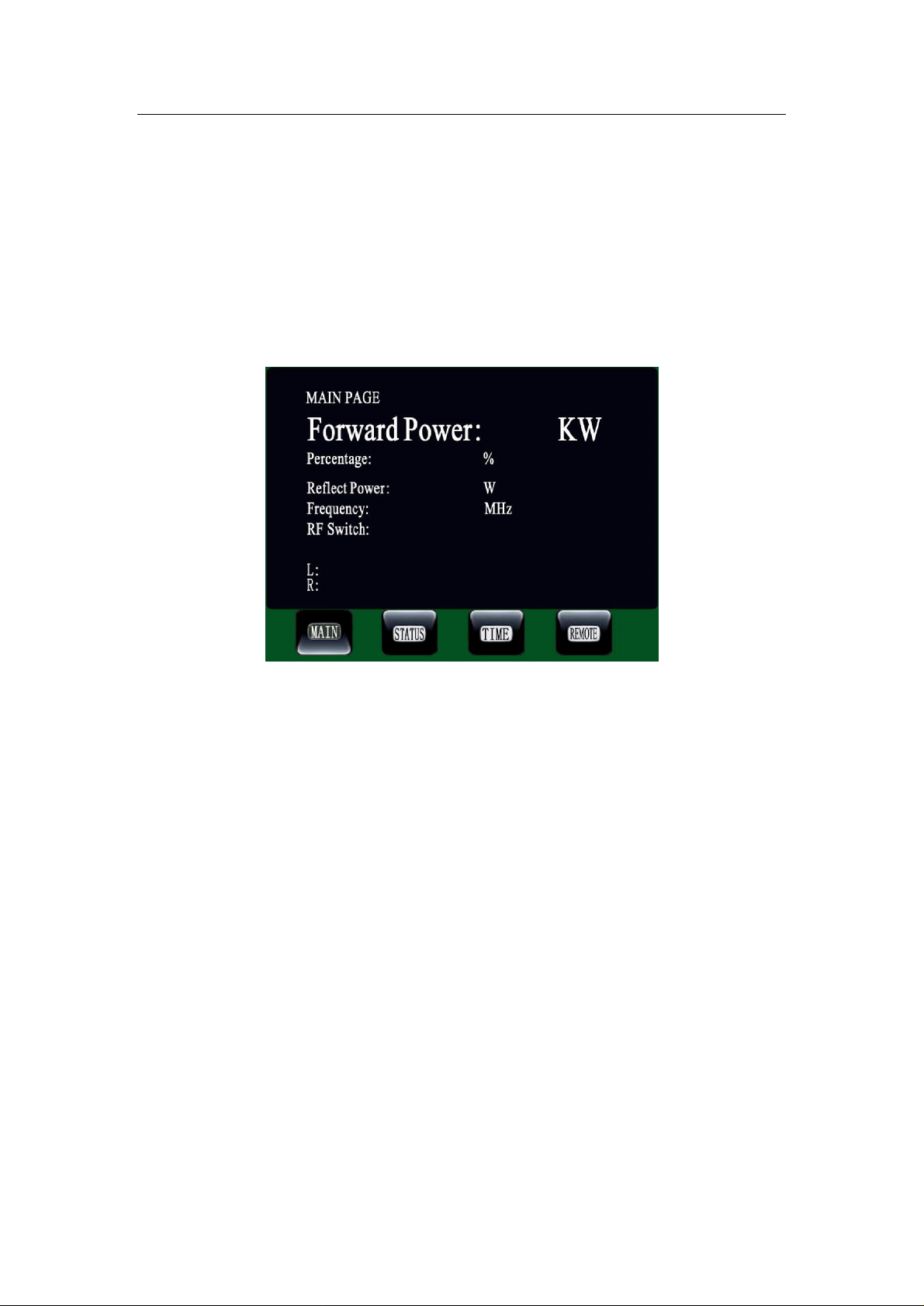
3.3 MAIN PAGE
Power Forward: forward power, display only
Percentage: forward percentage setting, setting parameter.
Power Reflect: reflect power, display only.
Frequency: RF frequency, reading from working exciter, display only.
L:/ R: Audio bar, indicating modulating deviation, display only.
For TV transmitter, the main page is slightly different from this.
3.4 STATUS PAGE
www.fmuser.org
Page 27
www.fmuser.org
N
ormal status
This page display running status of all components. Click on status block can
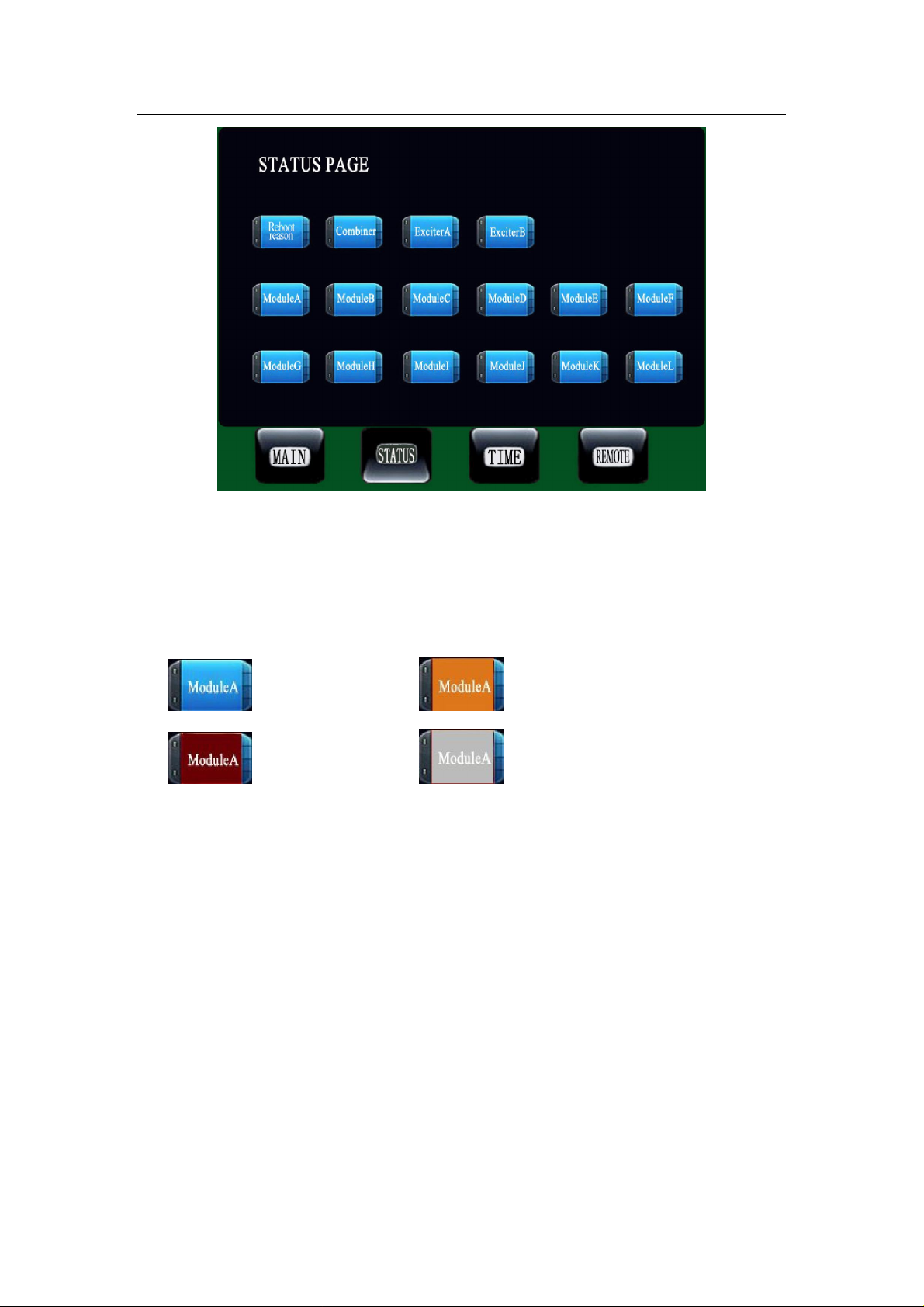
enter to corresponding component page to see its detail information.
Different color of each component indicate its running status, it is defined as
follow:
Blue:
Red:
l Normal status: system is running in good condition, RF output power keeps
constant to setting power.
l Warning status: component has some thing wrong (see parameter’s color in the
component by clicking on the component block), RF output power remains but
may not reach setting power.
l Critical status: RF power will reboot.
l Not online status: Indicate the component is absent or not connected properly or
not powered on or severe communication error occurs. RF output power will drop
or turn off.
Critical status
Yellow:
Warning status
Grey:
Not online status
3.4.1 Reboot Reason
www.fmuser.org
Page 28
www.fmuser.org
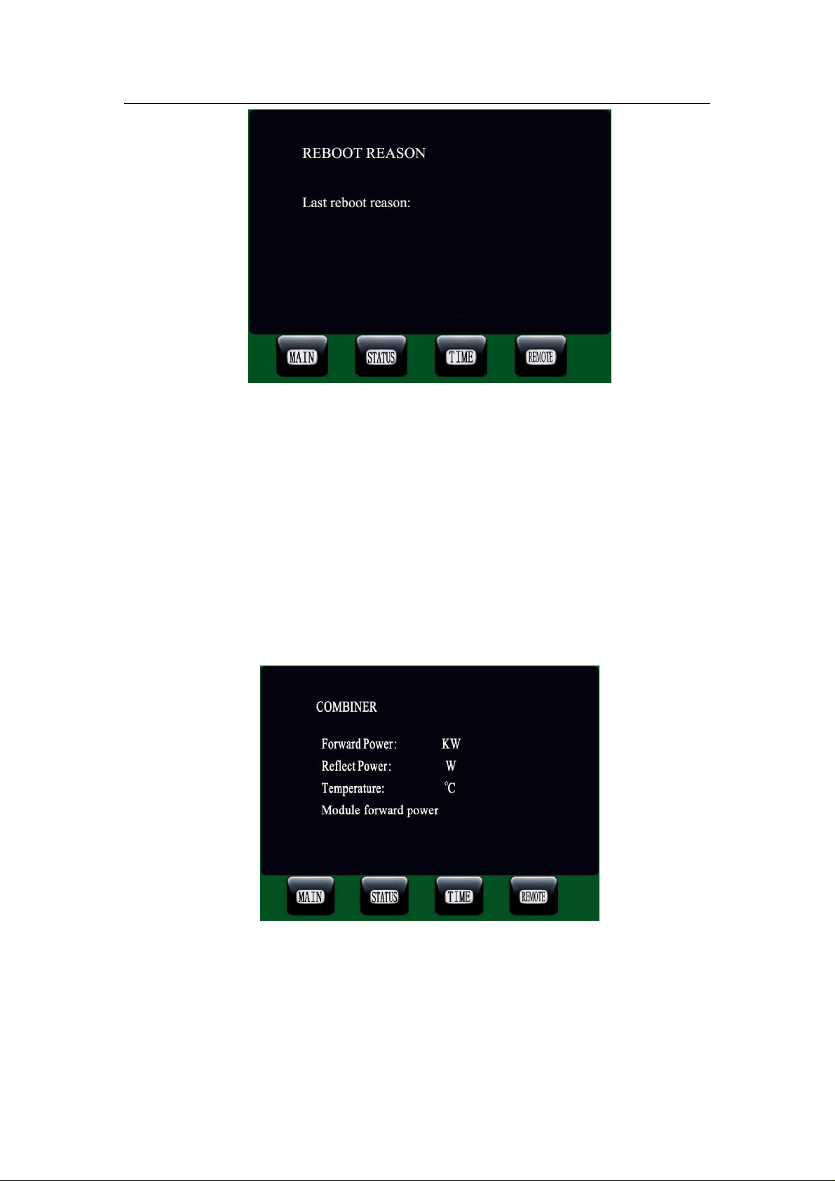
Last Reboot Reason:
--No reboot
--Forward power is too high
--Reflect power is too high
--The temperature of combiner is too high
--Unbalanced power is too high
3.4.2 Combiner Working Status
Forward Power: Combiner Forward Power
Reflect Power: Combiner Reflect Power
Temperature: Combiner Temperature
www.fmuser.org
Page 29
www.fmuser.org
Module forward power: The Forward Power of each amplifier
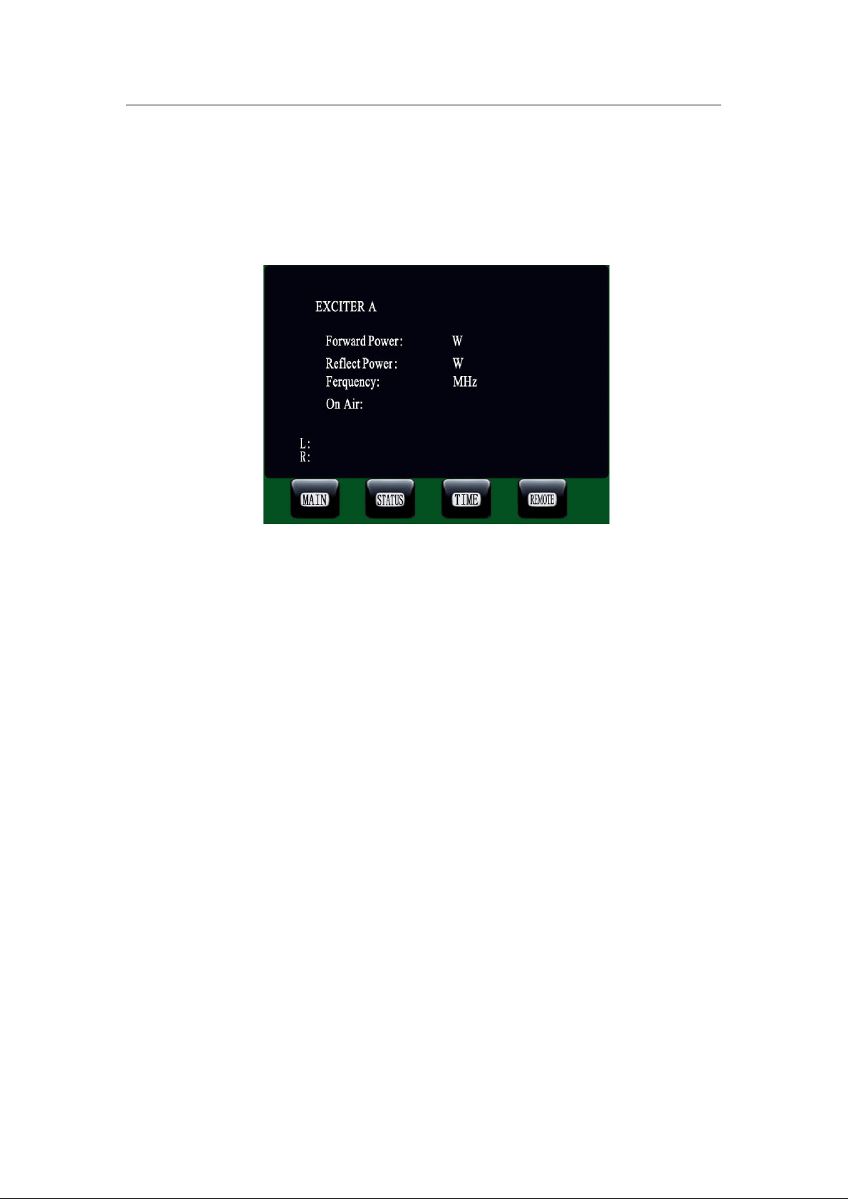
3.4.3 Exciter Working Status
Forward Power:Exciter Forward Power
Reflect Power:Exciter Reflect Power
Frequency: Exciter working frequency
On Air: ON---Exciter’s RF power turned on
OFF—Exciter’s RF turned off
L: Exciter left audio
R: Exciter right audio
www.fmuser.org
Page 30
www.fmuser.org
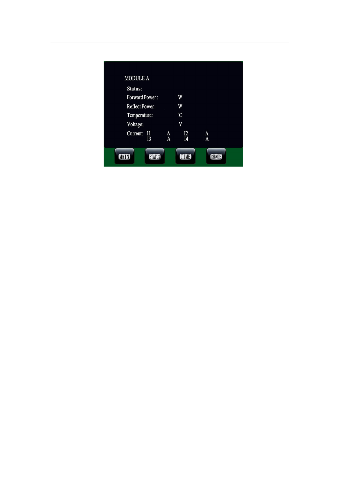
3.4.4 Power Amplifier Working Status
Status: Working—Power Amplifier is working normally
Booting--Power Amplifier is booting
Blocked--Power Amplifier is on protecting status; Because
of the self-protection, it would be rebooted and
turns on the RF in 10 seconds when extremely
case occurs. If the reboot failed 3 times
consecutively, then the power amplifier would
turn off the RF permanently until manually
disconnect the amplifier’s power and then
reconnect (cold reboot).
Absent-- Power Amplifier can not communicate with CCU.
Forward Power: Forward Power of the module
Reflect Power: Reflect Power of the module
Temperature: temperature of the module
Voltage: Amplifier’s power supply voltage, 48V/32V
Current: Each power amplifier unit has four amplifier modules;
this column is used to display the current of these four
amplifier modules.
www.fmuser.org
Page 31
www.fmuser.org
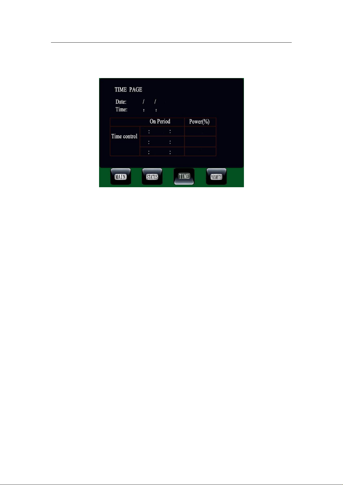
3.5 Time & Period Control
Date: Set date or display date. The format is: YY/MM/DD DAY
Time: Set time or display time. The format is: HH:MM:SS
Time Control:
Enabled: Time Period Control is enabled.
Disabled: Time Period Control is disabled.
Period setting: There are three time period in one day, the format is as follow:
Start Time End Time Period Power (%)
Period1 HH:MM HH: MM 0%--100%
Period2 HH:MM HH: MM 0%--100%
Period3 HH:MM HH: MM 0%--100%
Comment: for detail information about time period control refer to System
Control section.
www.fmuser.org
Page 32
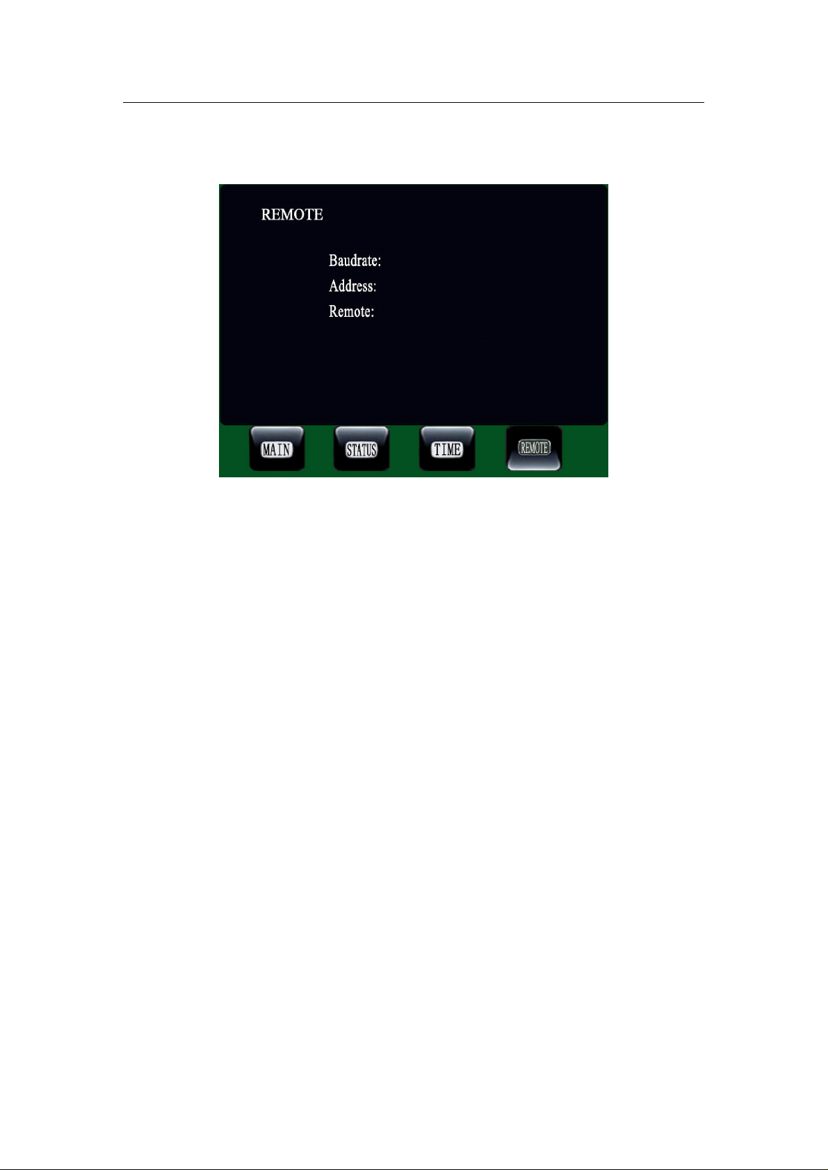
3.6 Remote control
www.fmuser.org
Baud rate: Setting remote communications baud rate.
Address: Setting remote communications address.
Remote: Enabled — parameters can only be changed remotely.
Disabled—parameters can be changed only locally.
www.fmuser.org
 Loading...