

Page 1
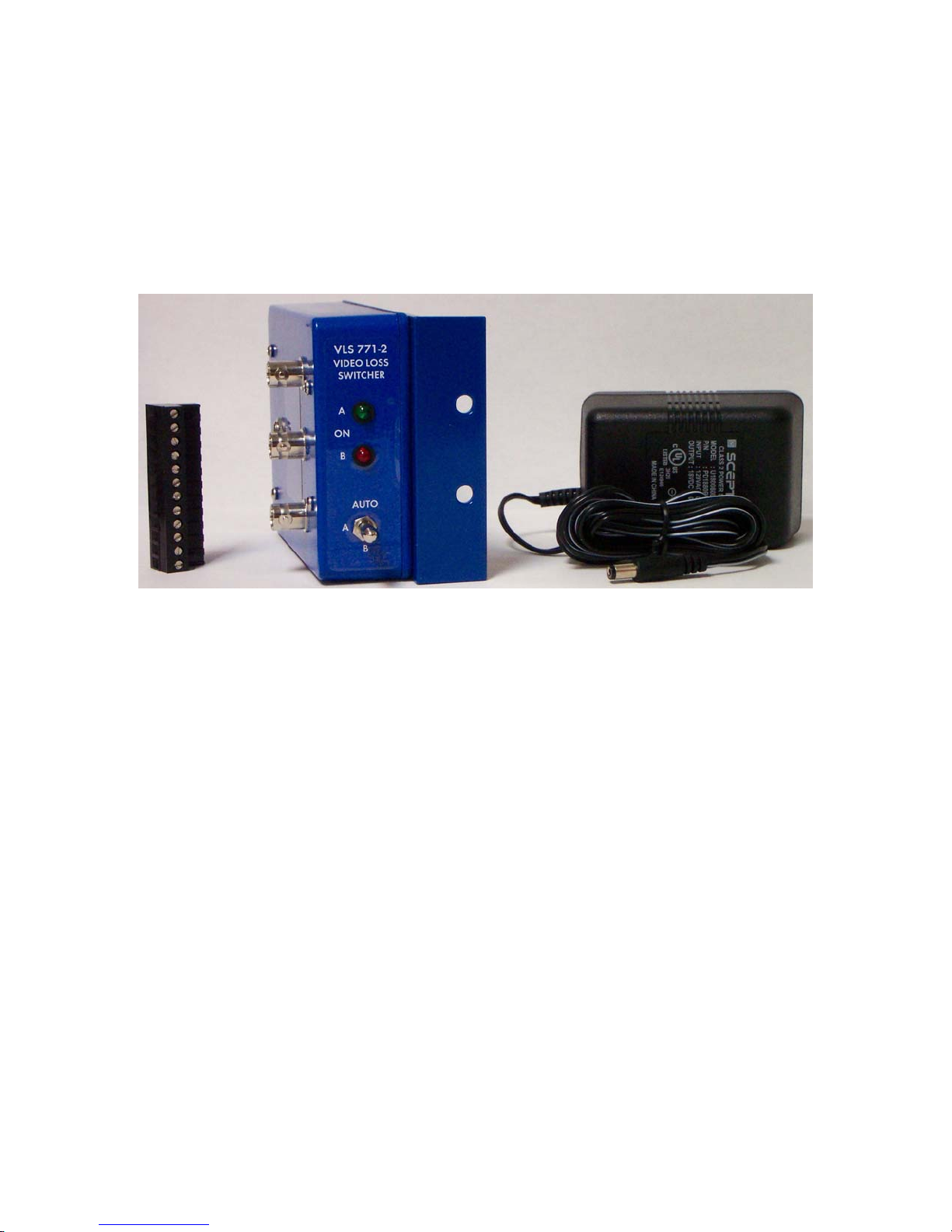
VLS771
VIDEO LOSS SWITCHER
INSTALLATION MANUAL
IB 627901
Page 2

DESCRIPTION
VIDEO LOSS SWITCHER
VLS771
The
VLS771 V
IDEO LOSS SWITCHER
is an automatic 2X1 Stereo audio follow
video switching system that reacts to the loss of Horizontal Sync pulses.
This device monitors the Primary video source and switches both video and
Left and Right Stereo balanced audio sources to the secondary when the
primary video signal ceases. The unit switches back to the primary channel
when the video returns. If a power failure occurs the unit will
automatically switch to the secondary video and audio.
The unit can be used to engage a hot standby source or to put up a test
pattern when main video fails. This system will maintain your video and
stereo audio integrity and reduce trouble calls. It can also be used where
unattended video switching must occur.
FEATURES
Features of the VLS771 include a front panel three position command
switch which is used to manually force either primary, secondary, or
automatic video and audio switching.
Also included is a Presents of video front panel LED which indicates
the status of the video on the primary channel.
Standard BNC connectors are used for the video inputs and output, and a
plug-in style removable screw terminal connector is used for the balanced
stereo audio inputs and outputs. This audio plug can be pre-wired thus
reducing your installation time.
This switcher is housed in a sturdy aluminum die cast box which is
completely RF shielded. The box can be mounted in the front or rear of your
rack with the standard mounting bracket.
ET-UP AND INSTALLATION
S
Remove the equipment from the packing materials. The following
materials should be supplied with each order.
QTY 1 VLS771 (Blue Box).
QTY 1 Power Cube +24 VDC.
QTY 1 12 Position Plug Audio Connector (may be attached).
QTY 1 Rack Mount Angle Bracket (may be attached).
VLS771.ISB PAGE 1 OF 3
Page 3

SET-UP AND INSTALLATION (continued)
Locate a convenient place in your rack and mount the unit using the
handy Rack Mount Angle Bracket. Next attach the Primary video signal to the
input BNC connector labeled (A INPUT). Then attach the Secondary video
signal to the BNC connector labeled (B INPUT). The BNC connector labeled
(COM OUTPUT) is the output of the video switch. The video that is selected
either manually or automatically will appear at this connector.
The 12 position snap in audio connector is numbered from left to right,
1 to 12. The following is a table of the connections used to switch Balanced
audio from Primary to Secondary input. This audio switch is accomplished by
internal relay switching. In the event of power loss the audio is switched
to the Secondary audio.
1. A input Left Tip or +
2. A input Left Ring or -
3. COMM output Left Tip or +
4. COMM output Left Ring or -
5. B input Left Tip or +
6. B input Left Ring or -
7. B input Right Tip or +
8. B input Right Ring or -
9. COMM output Right Tip or +
10. COMM output Right Ring or -
11. A input Right Tip or +
12. A input Right Ring or -
CONNECTOR BLOCK DIAGRAM
1 2 3 4 5 6 7 8 9 10 11 12
T R T R T R T R T R T R
A OUT B B OUT A
LEFT INPUT RIGHT INPUT
When audio wiring is complete Plug in the power cube and attach the +24
VDC connector into the VLS771.
VLS771.ISB PAGE 2 OF 3
Page 4

OPERATION
With video present on the Primary channel (A) the green VIDEO ON LED
will be lit on the front of the unit. This indicates that video is present
at the Primary input. On the front panel there is a Three Position
SWITCH
SWITCH
, to move this switch it is necessary to
before trying to change its position.
DO NOT FORCE THE SWITCH.
PULL OUT THE HANDLE OF THE
LOCKING
There
are three command modes for the switch. The first is (A) this will cause the
VLS771 to manually force the video and audio switch to the A input source.
The second is (B) this will cause a manual switch to input B. The third
position is (AUTO) which stands for AUTOMATIC, this will automatically
switch the video from A to B when the video on A disappears and will switch
back when the video reappears. In all modes of operation the audio switches
with the video. If mono is to be switched the extra unused contacts of the
VLS771 can be used to activate an external alarm.
MAINTENANCE
There is no adjustment or calibration required with the VLS771.
SPECIFICATIONS
V
IDEO SPECIFICATION
Standard NTSC or PAL (Auto-Select)
Level (Composite Video) 0.7 to 2 Vp-p (1.0 Vp-p STD.)
Frequency Response > 0.2 dB from DC to 40MHz
Cross-Talk (Pri/Sec input) < 75 dB
Signal to Noise Ratio < 90 dB
Frequency Response Flat from Dc to 50KHz
Cross-Talk (Pri/Sec) < 80 dB
Cross-Talk (Left/Right) < 80 dB
Signal to noise ratio < 90 dB
Power requirement 24 VDC Power Cube (included)
Video Mode Switch 3 Position Locking Toggle
Enclosure 3.5 x 4.5 x 1.5 Die Cast Alm.
VLS771.ISB PAGE 3 OF 3
 Loading...