

Page 1
90mm Viper
REALISTIC STABLERIGID
Retract & Flaps Installed Strong durable EPO Smooth flying performance
Instruction Manual
操作手册
FMSMODEL.COM
Page 2

Page 3
WARNING
WARNING: Read the ENTIRE instruction manual to become familiar with the features of the product before operating.
Failure to operate the product correctly can result in damage to the product,personal property and cause serious injury.
This is a sophisticated hobby product and NOT a toy. It must be operated with caution and common sense and failure to do so
could result in injury or damage to the product or other property. This product is not intended for use by children without direct
adult supervision.
This manual contains instructions for safety operation and maintenance. It is essential to read and follow all the instructions and
warnings in the manual prior to assembly, setup or use, in order to operate and avoid damage or serious injury.
p w
As the user of this product, you are solely responsible for operating in a manner that does not endanger yourself and others or
result in damage to the product or the property of others. This model is controlled by a radio signal subject to interference from
many sources outside your control. This interference can cause momentary loss of control so it is advisable to always keep a
safe distance in all directions around your model, as this margin will help avoid collisions or injury.
Age Recommendation: Not for children under 14 years. This is not a toy.
·Never operate your model with low transmitter batteries.
·Always operate your model in an open area away from cars, traffic or people.
·Avoid operating your model in the street where injury or damage can occur.
·Never operate the model in populated areas for any reason.
·Carefully follow the directions and warnings for this and any optional support equipment you use (chargers,rechargeable
battery packs, etc.)
·Keep all chemicals, small parts and anything electrical out of the reach of children.
·Moisture causes damage to electronics. Avoid water exposure to all equipment not specifically designed and protected for this
purpose.
·Never lick or any place of any your model in your mouth as it could cause serious injury or even death.
E
N
Lithium Polymer (Li-Po) Battery Warning
CAUTION: Always follow the manufacturer’s instructions for safe use and disposal of batteries. Fire, property
damage, or serious injury can result from the mishandling of Li-Po batteries.
By handling, charging or using a Li-Po Battery you assume all risks associated with lithium batteries.
If at any time the batteries begin to swell or balloon, discontinue use immediately!
Always store the batteries at room temperature in a dry area to extend the life of the battery. Always transport
or temporarily store the battery in a temperature range of 40-120F. Do not store the battery or model in a car or in direct sunlight.
If stored in a hot car, the battery can be damaged or even catch fire.
Never use a Ni-Mh Charger to charge Li-Po Batteries. Failure to charge the battery with a Li-Po compatible charger
may cause fire resulting in personal injury and property damage.
Never discharge Li-Po Cells below 3V.
Never leave charging batteries unattended.
Never charge damaged batteries.
Charging the Flight Battery Warning
Use a battery charger that is designed to safely charge the Li-Po Battery. Read the charger instructions care
fully before use. When charging the battery, make certain the battery is on a heat resistant surface. It is also highly
recommended to place the Li-Po Battery inside a fire resistant charging bag readily available at hobby shops or
online.
2
Page 4
E
N
Introduction
The FMS 90mm Viper is an upgrade from the best-selling 70mm
Viper, designed to provide the look and performance of a jet
fighter with the stability of a low-wing sport aircraft, so that more
pilots of all levels can enjoy the fun of EDF aircraft.
The combination of FMS high-efficiency 90mm 12-blade EDF
unit, high-power 3670-KV1950 inner running motor and
high-quality 120A ESC provides unparalleled performance to
the aircraft, and the throttle can respond instantly, making the
sound very immersive. When paired with 6S 5000– 6000mAh
45C battery, the top speed could hit 120+ MPH.
The 90mm Viper has a superior structure, which complements
the power system, enabling it to perform well in both high-speed
and low-speed flight. It can fly leisurely, fly fast, and even
aerobatics - the 90mm Viper is extremely manoeuvrable and
can effortlessly perform most aerobatic maneuvers such as
rolls, somersaults, and side spins
The 90mm Viper adopts the latest assembly structure and
techniques, such as screw-together airframe, ball-linked control
surfaces, high strength spars, multi-connector, so that it can be
assembled in a very short time. In addition, the electronic
retracts in the locked-rotor mode and the CNC-processed
kneeling structure metal landing gear set are used to effectively
resist violent landing; the large-sized durable tires are used to
facilitate the take-off and landing on various grounds such as
cement roads, grass, sand, etc.
No matter whether you have collected Vipers before, this newly
launched FMS 90mm Viper EDF is very worth looking forward
to. It can give you a refreshing experience in terms of details and
performance. It is the best choice for players to experience
large-scale aircraft.
Features:
• Electronic configuration: high-quality 120A ESC, high-power
3670 KV1950 inner running motor, high-efficiency 90mm 12
-blade EDF unit, high-precision metal digital servos.
• The extremely wide performance range and speed range
can be used for leisure flying and aerobatics, and the overall
take-off, flight and landing process is easy and smooth.
• The locked-rotor mode electronic retracts with overcurrent
protection function and the CNC-processed kneeling structure
metal landing gear set, effectively resist violent landing
• Functional navigation lights.
• Functional flaps
• The buckle structure design effectively prevent the cockpit
from falling off during flight.
• The large size battery compartment is convenient for placing
batteries of different sizes from different manufacturers.
• Large size durable tires for taking off and landing on rough
ground.
• Preinstalled ball-linked control horns for accurate and
precise movements.
• Screw assembly structure, , eliminating the trouble of
applying glue
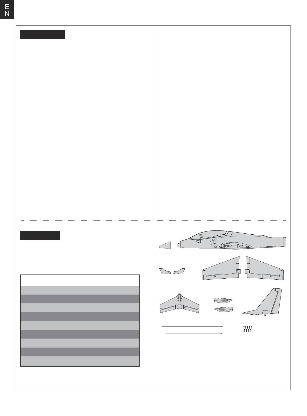
Kit contents
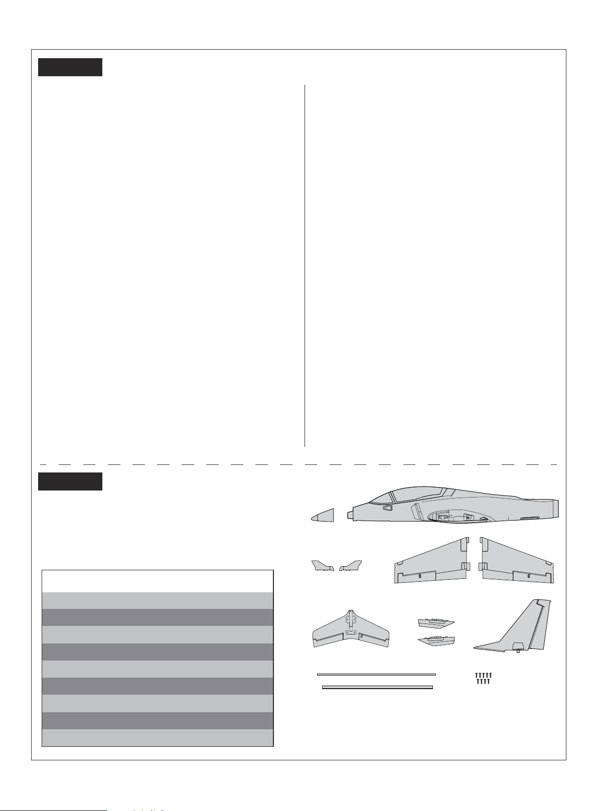
Before assembly, please inspect the contents of the kit. The
photo below details the contents of the kit with labels. If any
parts are missing or defective, please identify the name or
part number (refer to the spare parts list near the end of the
manual) then contact your local shop or email us: support
@fmsmodel.com.
Specifications
Wingspan: 1400mm /55in
Overall Length: 1280mm /50.4 in
Flying Weight: Around 3250g
Motor Size: 3670 KV1950
Wing Load: 107.6g/dm²
Wing Area: 30.2dm²
ESC: 120A
Servo: 13g X 8
Recommended Battery: 22.2V 5000-6000mAh 45c
A. B.
C.
E.
H. I.
A:
Nose Cone
B:
Fuselage
C:
Winglet Set
D:
Main Wing
G:
H:
D.
F.
E:
Horizontal Stabilizer
F:
Ventral Fin Set
Vertical Fin
Wing Tubes
G.
I: Screw Set
3
Page 5
Model assembly
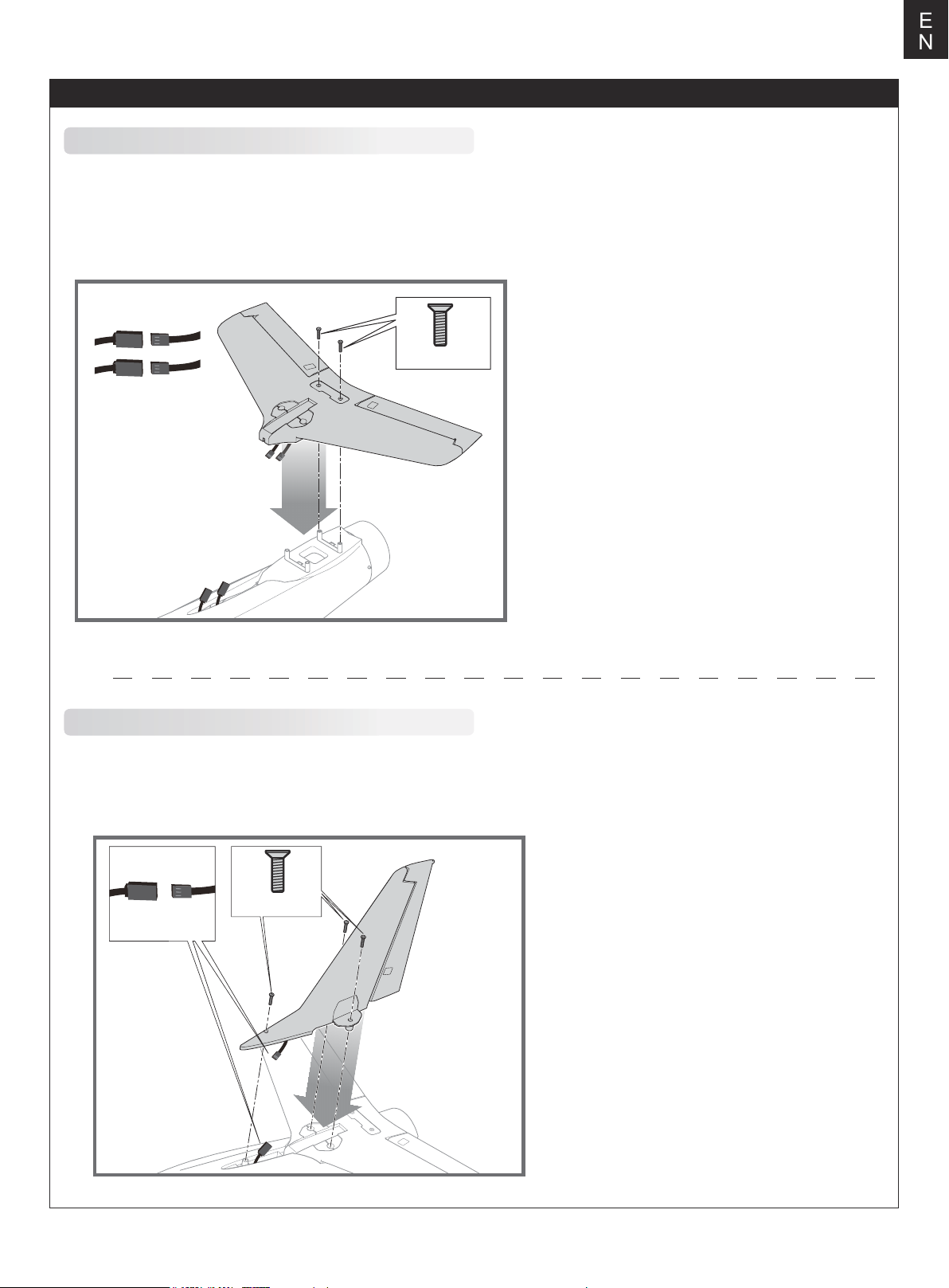
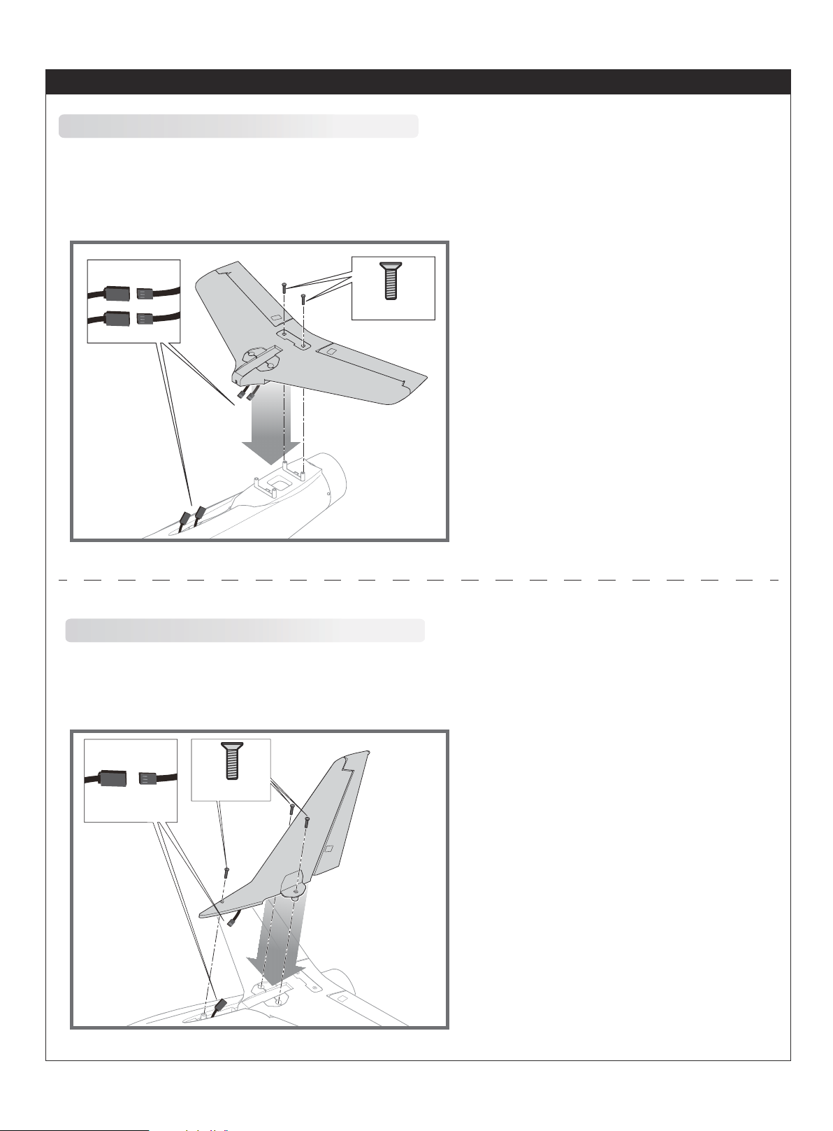
Horizontal stabilizer installation
1.Attach the horizontal stabilizer to the fuselage as shown.
2.Insert the included two screws (HKM 3.0*10) into the circular aluminum part. Do not lock the screws. And then put
the aluminum part into the slot shown in the figure.
3.Lock the horizontal stabilizer to fuselage by tightening the screws on the circular aluminum part.
HKM3.0 x 10mm
E
N
Vertical stabilizer installation
1.Connect the rudder servo connectors to the servo extensions in fuselage. Note the corresponding wire color.
2.Attach the vertical stabilizer to the corresponding slot at the rear of the fuselage as shown, and then use three
included screws (HKM 3.0*10) to fix it from the both sides of fuselage.
HKM3 .0x 10mm
4
Page 6
E
N
Model assembly
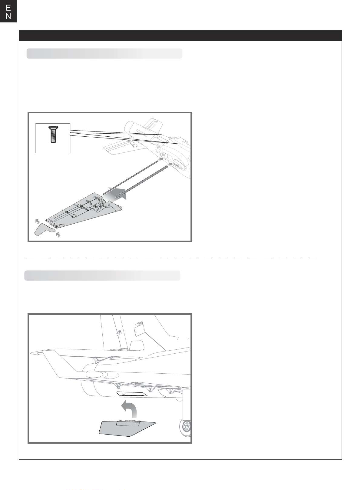
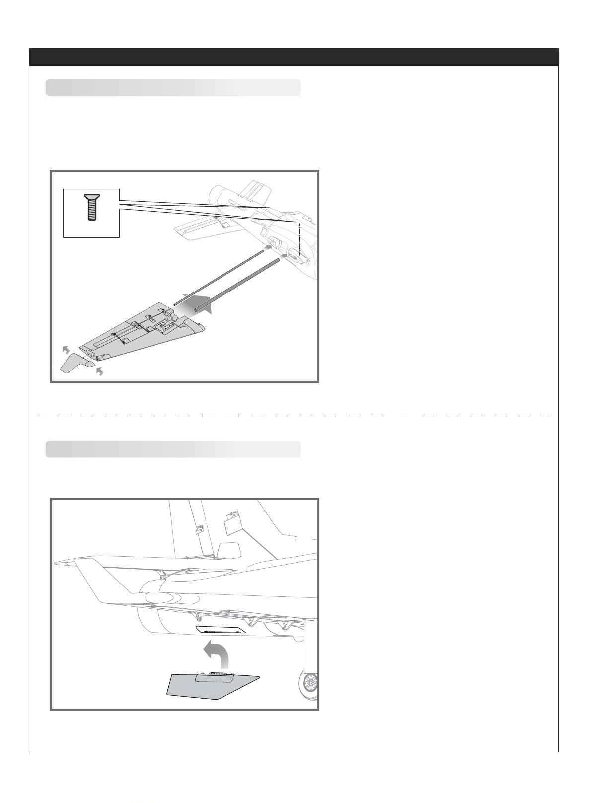
Main wing installation
1.Slide the wing spars into the fuselage as shown.
2.Install the left and right wing halves over the wing spars and into the wing slots. Be sure the connectors on both sides
are attached precisely and firmly.
3.Secure the left and right wings to the fuselage using four screws included (HKM 3.0*10)
4.Attach the winglet to the corresponding slot on main wing, then slide toward the rear of the fuselage to lock in place.
HKM3.0 x 10mm
Ventral Fin installation
Attach the left and right ventral fins to the slots at the bottom of fuselage, then slide toward the rear of the
fuselage to lock in place.
5
Page 7
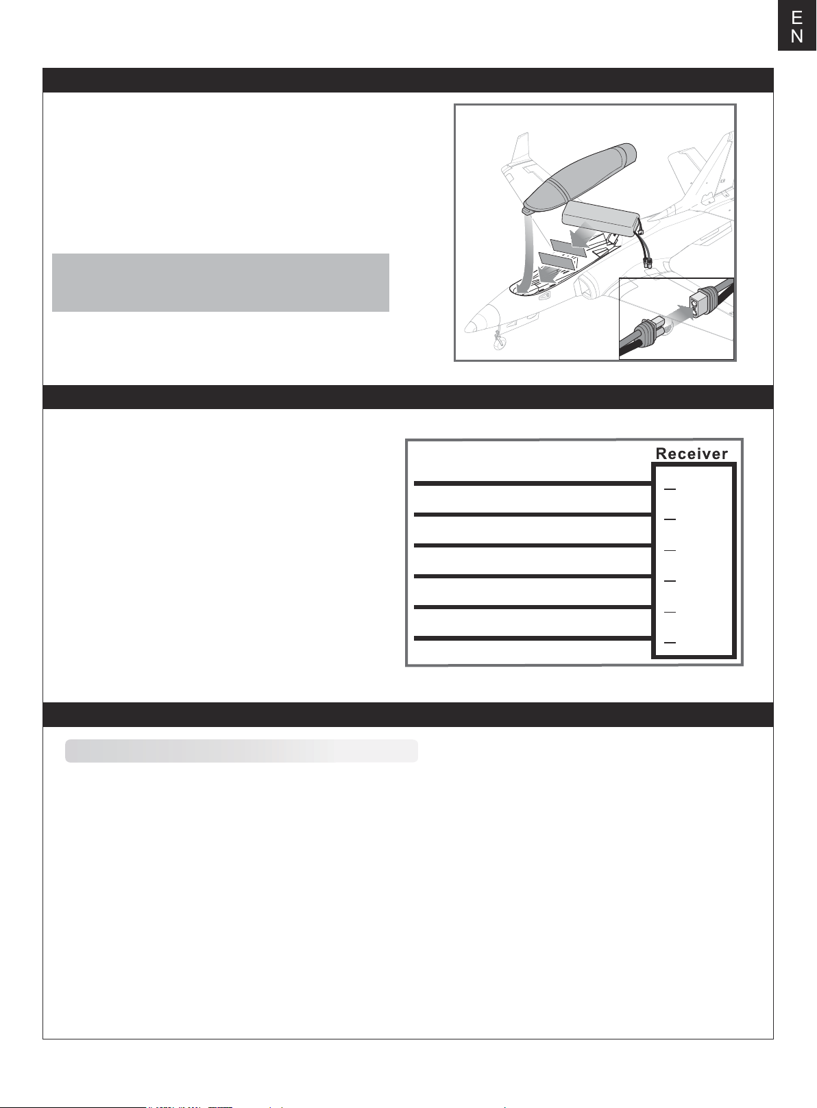
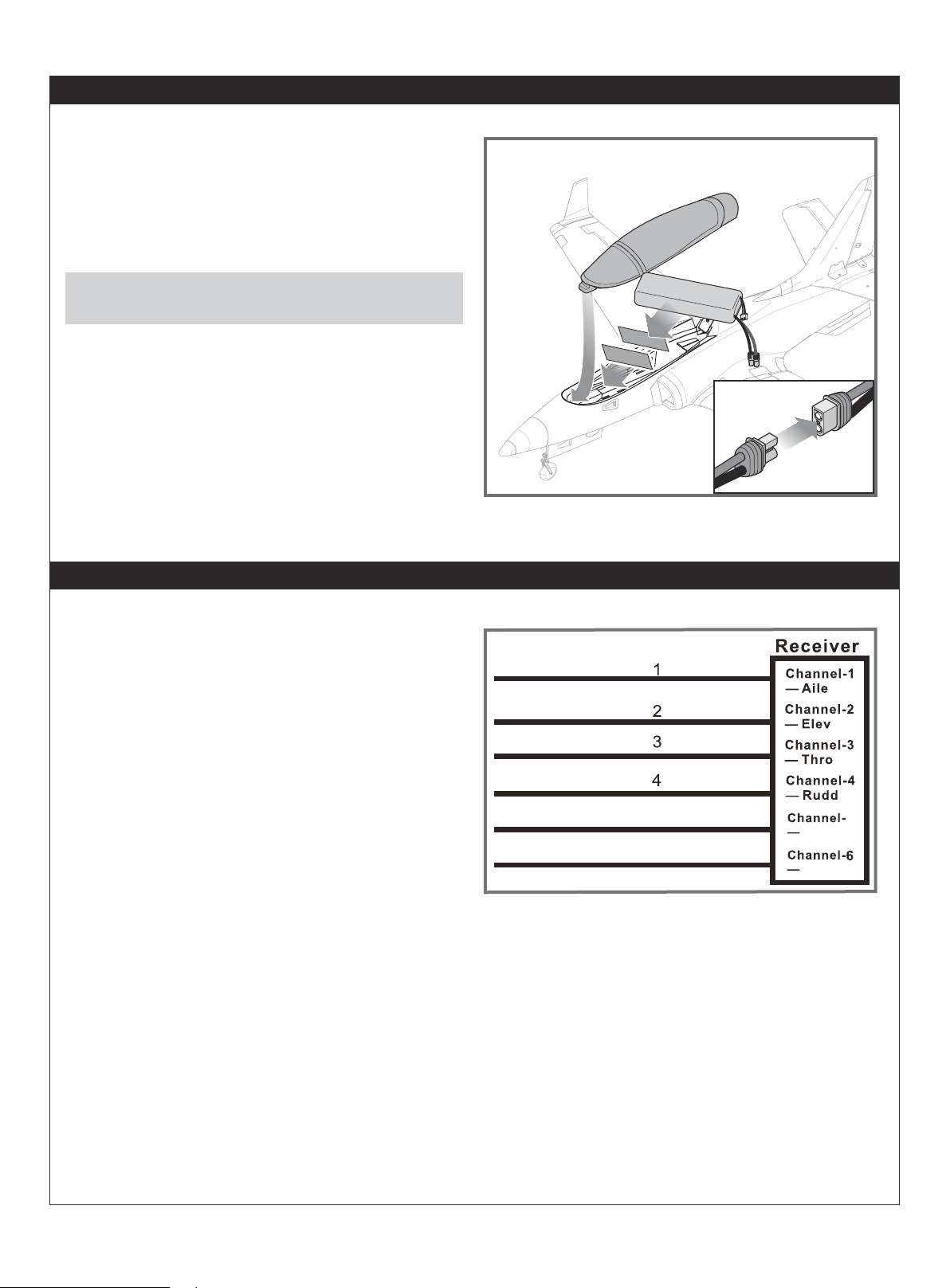
Battery installation
1.Pull back on the latch and remove the battery hatch.
2.Apply the hook tape to the cable end of the battery.
3.Slide the full charged battery into the battery compartment
with the power supply cable toward the rear end of the plane.
Note: The center of gravity can be adjusted by moving the
battery forward or aft.Having the correct center of gravity is
critical to achieving proper flight characteristics.
Receiver diagram
E
N
The cables from the servo connector board should be
connected to your receiver in the order shown. Note that the
LEDs can be powered by any spare channel on the receiver.
Tuck the wire leads into the recessed cavity towards the rear
of the battery hatch.
Aileron
EIevator
Throttle
Rudder
Gear
Spare
1
2
3
4
5
6
Channel-1
Aile
Channel-2
Elev
Channel-3
Thro
Channel-4
Rudd
Channel-5
Gear
Channel-6
Spare
Get your model ready to fly
Important ESC and model information
The ESC included with the model has a safe start. If the motor battery is connected to the ESC and the throttle stick is not in
1.
the low throttle or off position, the motor will not start until the throttle stick is moved to the low throttle or off position. Once the
throttle stick is moved to the low throttle or off position, the motor will emit a series of beeps. Several beeps with the same tune
means the ESC has detected the cells of the battery. The count of the beeps equals the cells of the battery. The motor is now
armed and will start when the throttle is moved.
The motor and ESC come pre-connected and the motor rotation should be correct. If for any reason the motor is rotating in the
2.
wrong direction, simply reverse two of the three motor wires to change the direction of rotation.
The motor has an optional brake setting. The ESC comes with brake switched off and we recommend that the model be flown
3.
with the brake off. However, the brake could be accidentally switched on if the motor battery is connected to the ESC while the
throttle stick is set at full throttle. To switch the brake off, move the throttle stick to full throttle and plug in the motor battery. The
motor will beep one time. Move the throttle stick to low throttle or the off position. The motor is ready to run and the brake will
be switched off.
Battery Selection and Installation. We recommend the 22.2V4000mAh-5000mAh 45c Li-Po battery. If using another battery,
4.
the battery must be at least a 22.2V4000mAh-5000mAh 45c battery. Your battery should be approximately the same capacity,
dimension and weight as the 22.2V4000mAh-5000mAh 45c Li-Po battery to fit the fuselage without changing the center of
gravity significantly.
6
Page 8
E
N
Transmitter and model setup
Before getting started, bind your receiver with your transmitter.
Please refer to your transmitter manual for proper operation.
CAUTION: To prevent personal injury, DO NOT install the
propeller assembly onto the motor shaft while testing the control
surfaces. DO NOT arm the ESC and do not turn on the
transmitter until the Transmitter Manual instructs you to do so.
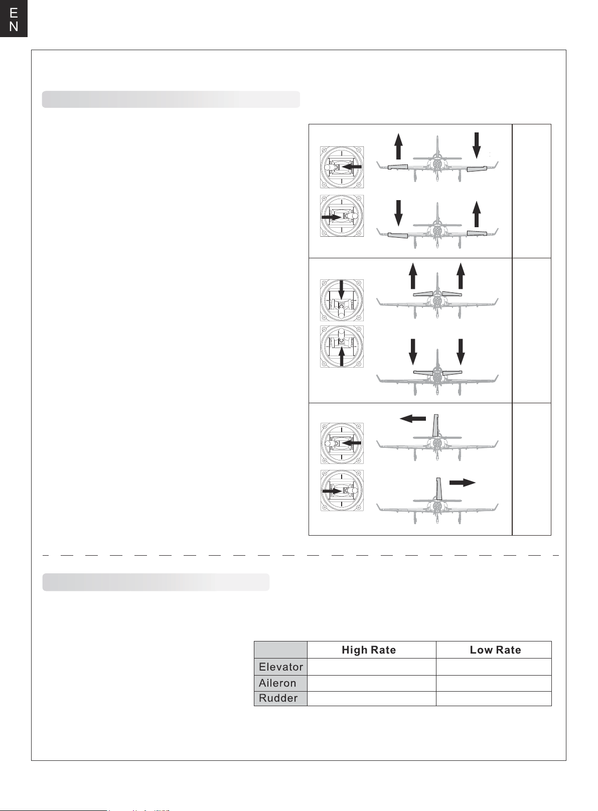
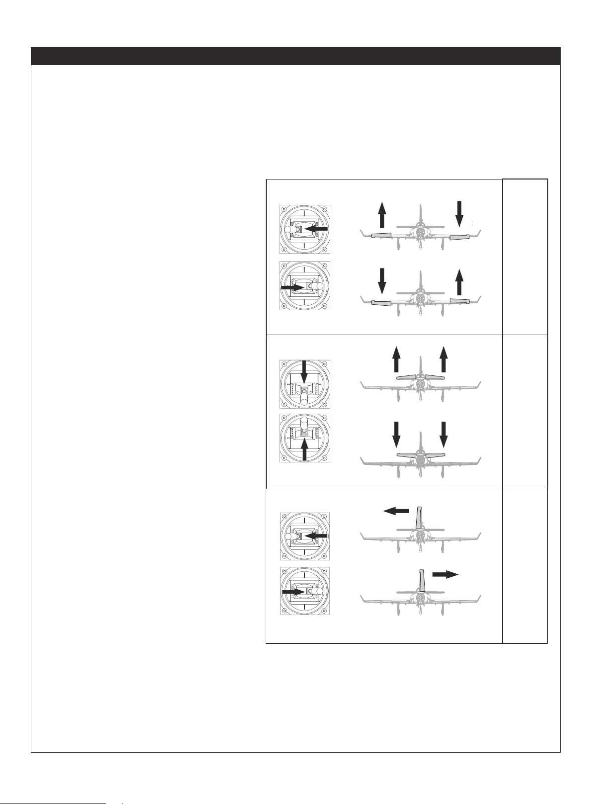
Tips: Make sure all control sticks on your radio are in the neutral
position (rudder, elevator, ailerons) and the throttle is in the OFF
position. Make sure both ailerons move up and down (travel) the
same amount. This model tracks well when the left and right
ailerons travel the same amount in response to the control stick.
Move the controls on the transmitter to make sure the aircraft
control surface moves correctly. See diagrams right.
Bank left
Aileron
Bank right
Climb
Elevator
Descend
Steer left
Steering Rudder
Steer right
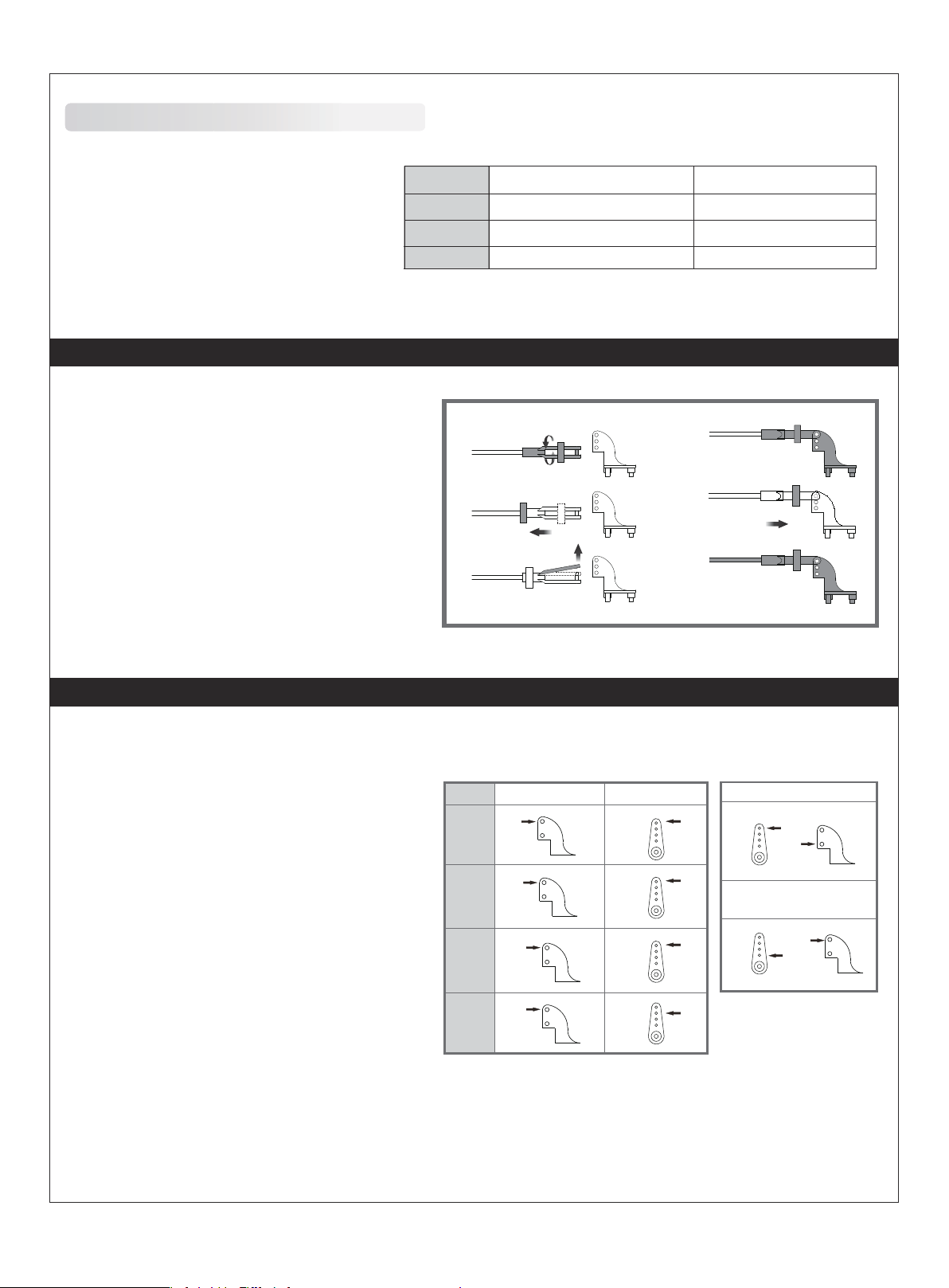
Control throws
The suggested control throw setting for the 80mm Dassault Rafale are as follows (dual rate setting):
Tips: On the first flight, fly the model in low rate.
The first time you use high rates,be sure to fly at
low to medium speeds. High rate, as listed, is
only for EXTREME maneuvering.
16mm up / dowm 12mm up / dowm
12mm up / dowm
11mm left / right
7
8mm up / dowm
7mm left / right
Page 9
Clevis installation
E
N
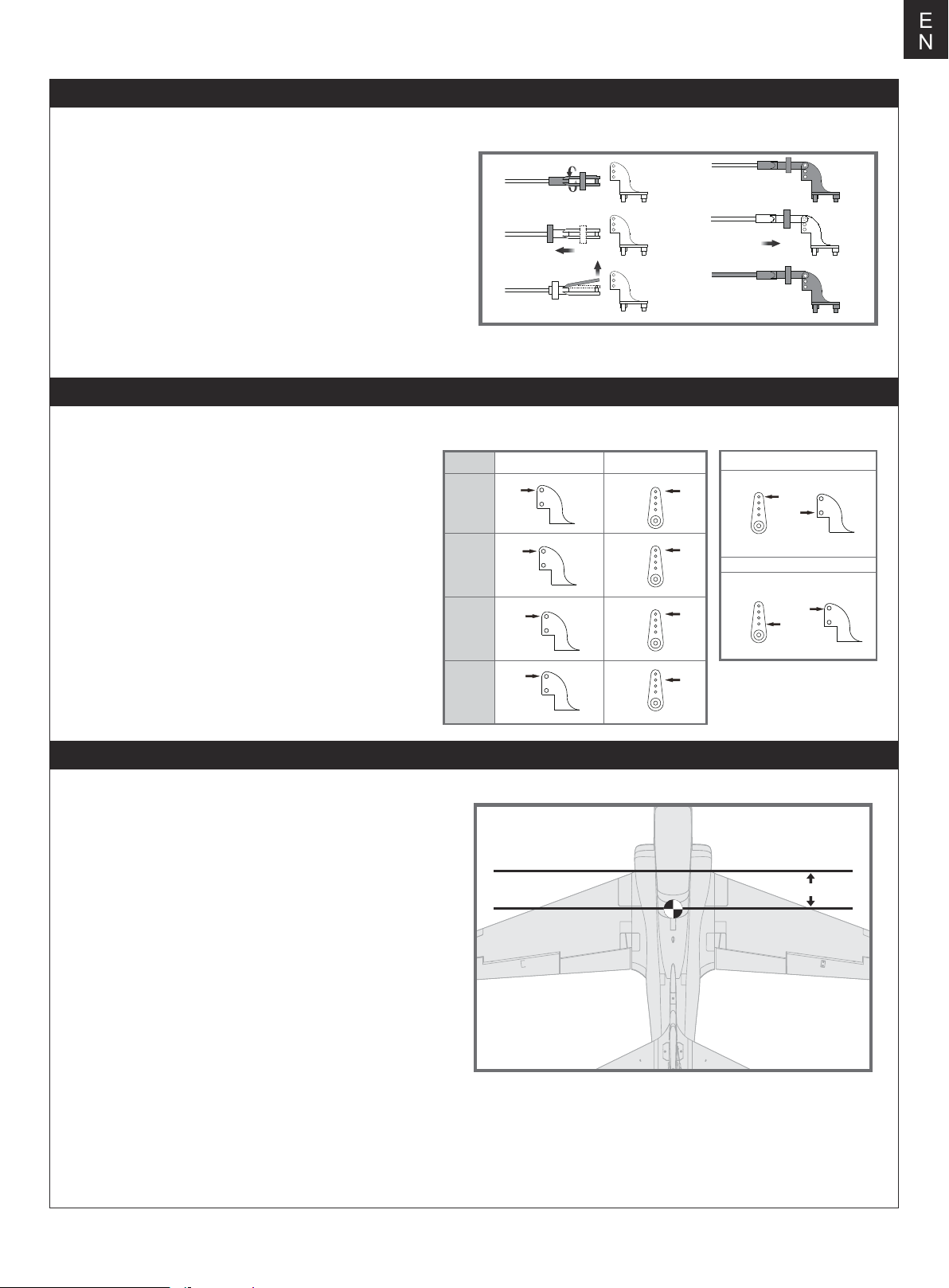
1.Pull the tube from the clevis to the linkage.
2.Carefully spread the clevis, then insert the clevis pin into the
desired hole in the control horn.
3.Move the tube to hold the clevis on the control horn.
Control horn and servo arm settings
The table shows the factory settings for the control horns
and servo arms. Fly the aircraft at the factory settings
before making changes.
After flying,you may choose to adjust the linkage positions
for the desired control response.
a.
b.
c.
ElevatorRudderAileronsCanard
Horns Arms
d.
e.
f.
More control throw
Less control throw
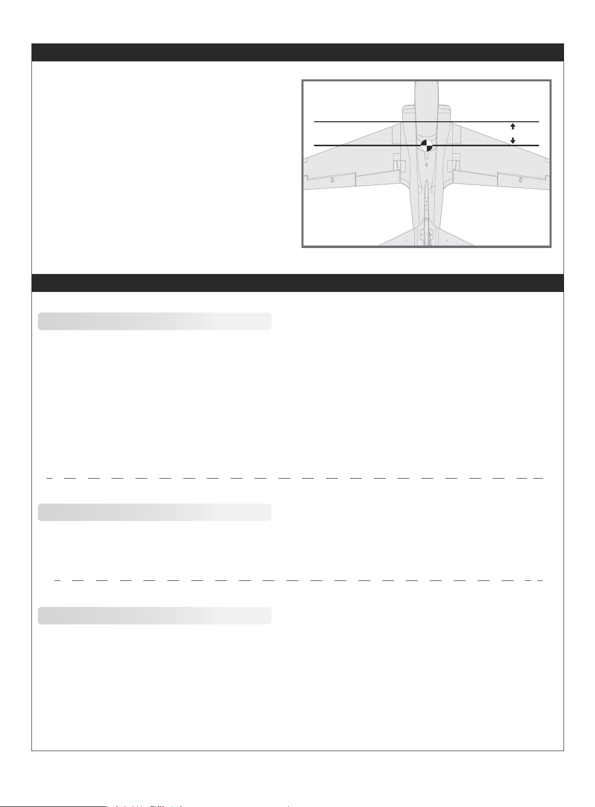
Check the C.G. (Center of gravity)
When balancing your model, adjust the battery as necessary
so the model is level or slightly nose down. This is the correct
balance point for your model. After the first flight, the CG
position can be adjusted for your personal preference.
1. The recommended Center of Gravity (CG) location for your
model is(110-120mm) from the leading edge of the main wing
(as shown) with the battery pack installed. Mark the location of
the CG on top of the wing.
2. When balancing your model, support the plane at the marks
made on the bottom of the main wing with your fingers or a
commercially available balancing stand. This is the correct
balance point for your model. Make sure the model is assembled
and ready for flight before balancing.
110-120mm
8
Page 10
E
N
Before flying the model
Find a suitable flying site
Find a flying site clear of buildings, trees, power lines and
other obstructions. Until you know how much area will be
required and have mastered flying your plane in confined
spaces, choose a site which is at least the size of two to three
football fields - a flying field specifically for R/C planes is best.
Never fly near people - especially children, who can wander
unpredictably.
Perform the range check for your plane
As a precaution, an operational ground range test should be
performed before the first flight each time you go out.
Performing a range test is a good way to detect problems
that could cause loss of control such as low batteries, defective
or damaged radio components, or radio interference. This
usually requires an assistant and should be done at the actual
flying site you will be using.
First turn on the transmitter, then install a fully-charged battery
into the fuselage. Connect the battery and install the hatch.
Flying course
Take off
While applying power, slowly steer to keep the model straight.
The model should accelerate quickly. As the model gains flight
speed you will want to climb at a steady and even rate. It will
climb out at a nice angle of attack (AOA).
Flying
Always choose a wide-open space for flying your plane. It is
ideal for you to fly at a sanctioned flying field. If you are not
flying at an approved site always avoid flying near houses,
trees, wires and buildings. You should also be careful to avoid
flying in areas where there are many people, such as busy
parks, schoolyards, or soccer fields. Consult laws and
ordinances before choosing a location to fly your aircraft. After
takeoff, gain some altitude. Climb to a safe height before trying
technical manoeuvres, including high speed passes, inverted
flight, loops, and point rolls.
Remember, use care not to bump the throttle stick. Otherwise,
the propeller/fan will turn and possibly cause damage or injury.
Note: Please refer to your Transmitter Manual that came with
your radio control system to perform a ground range check. If
the controls are not working correctly or if anything seems
wrong, do not fly the model until you correct the problem. Make
certain all the servo wires are securely connected to the
receiver and the transmitter batteries have a good connection.
Monitor your flight time
Monitor and limit your flight time using a timer (such as on a
wristwatch or in your transmitter if available). When the
batteries are getting low you will usually notice a performance
drop before the ESC cuts off motor power, so when the plane
starts flying slower you should land. Often (but not always)
power can be briefly restored after the motor cuts off by
holding the throttle stick all the way down for a few seconds.
To avoid an unexpected dead-stick landing on your first flight,
set your timer to a conservative 4 minutes. When your alarm
sounds you should land right away.
Landing
Land the model when you hear the motor pulsing (LVC) or if
you notice a reduction in power. If using a transmitter with a
timer, set the timer so you have enough flight time to make
several landing approaches.
The model’s three point landing gear allows the model to land
on hard surfaces. Align model directly into the wind and fly
down to the ground. Fly the airplane down to the ground using
1/4-1/3 throttle to keep enough energy for proper flare. Before
the model touches down, always fully decrease the throttle to
avoid damaging the propeller or other components. The key to
a great landing is to manage the power and elevator all the
way to the ground and set down lightly on the main landing
gear. After a few flights you will find the model can be set down
lightlyon the mains and you can hold the nose wheel off
balancing themodel on the mains until it slows and gently
settles the nose.
Maintenance
Repairs to the foam should be made with foam safe adhesives
such as hot glue, foam safe CA, and 5min epoxy. When parts
are not repairable, see the Spare Parts List for ordering by item
number.
Always check to make sure all screws on the aircraft are
tightened. Pay special attention to make sure the spinner is
firmly in place before every flight.
9
Page 11
Trouble shooting
Problem Possible Cause Solution
E
N
Aircraft will not respond to
the throttlebut responds to
other controls.
Extra propeller noise or
extra vibration.
Reduced flight time or
aircraft underpowered.
Control surface does not
move, or is slow to respond
to control inputs.
Controls reversed.
-Motor loses power
-Motor power pulses then
motor loses power.
-ESC is not armed.
-Throttle channel is reversed.
-Damaged spinner, propeller,
motor or motor mount.
-Loose propeller and spinner parts.
-Propellor installed backwards.
-Flight battery charge is low.
-propeller installed backward.
-Flight battery damaged.
-Control surface, control horn,
linkage or servo damage.
-Wire damaged or connections
loose.
Channels are reversed in the
transmitter.
-Damage to motor, or battery.
-Loss of power to aircraft.
-ESC uses default soft Low Voltage
Cutoff(LVC).
-Lower throttle stick and throttle trim to lowest settings.
-Reverse throttle channel on transmitter.
-Replace damaged parts.
-Tighten parts for propeller adapter, propeller and spinner.
-Remove and install propeller correctly.
-Completely recharge flight battery.
-Replace flight battery and follow flight battery
instructions.
-Replace or repair damaged parts and adjust controls.
-Do a check of connections for loose wiring.
Do the control direction test and adjust controls for
aircraft and transmitter.
-Do a check of batteries, transmitter, receiver, ESC, motor
and wiring for damage(replace as needed).
-Land aircraft immediately and recharge flight battery.
LED on receiver flashes
slowly.
Power loss to receiver.
-Check connection from ESC to receiver.
-Check servos for damage.
-Check linkages for binding.
Spare parts list content
FMSTB101
FMSTB102
FMSTB103
FMSTB104
FMSTB105
FMSTB106
FMSTB107
FMSTB108
FMSTB109
FMSTB110
FMSTB111
FMSTB112
FMSTB113
FMSTB114
FMSTB114-1
Visit our website: www.fmsmodel.com to see photo of this product. Enter the key word "ESC" in the search bar for the
stock ESC instruction manual.
Fuselage
Main Wing Set
Vertical Stabilizer
Horizontal Stabilizer
Canopy
Nose Cone
Winglet Set
Linkage Set
Control Horn Set
Wheel Set
Screw Set
Ventral Fin Set
Decal Set
Front Landing Gear Door
Main Landing Gear Door
FMSTB115
FMSTB116
FMSTB117
FMSTB118
FMSTB119
FMSTB120
FMSTB121
FMSRE064
FMSRE065
FMS90MM
FMSDF011
PRESC039
PR13MGDP
PR13MGDR
Wing Tubes
Lighting Set
Pilot
Nose Gear Strut
Main Gear Struts
Front Landing Gear System
Main Landing Gear System
Electronic Retract
Electronic Retract
90MM Ducted Fan (12-blade)
Ducted Fan With
Motor3670-1950KV (plastic) 6S
120A ESC
Predator 13g digital metal gear
servo positive
Predator 13g digital metal gear
servo reverse
10
Page 12
E
N
User Manual of Brushless Speed Controller
Thanks for purchasing our Electronic Speed Controller (ESC). High power system for RC model is very dangerous,
please read this manual carefully. In that we have no control over the correct use, installation, application, or
maintenance of our products,no liability shall be assumed nor accepted for any damages, losses or costs resulting
from the use of the product. Any claims arising from the operating, failure or malfunctioning etc. will be denied. We
assume no liability for personal injury, property damage or consequential damages resulting from our product or
our workmanship. As far as is legally permitted, the obligation to compensation is limited to the invoice amount of
the affected product.
Specifications
Weight
L*W*H
(mm)
32*12*4.5
38*18*6
38*18*7
48*22.5*6
42*25*8
68*25*8
68*25*8
65*25*12
65*29*10
77*35*14
86*38*12
86*38*12
86*38*12
Model
6A
12A
12AE
15A
20A
30A
40A
40A-UBEC
50A-UBEC
60A-UBEC
60A-UBEC
80A-UBEC
80A-UBEC
Cont
Current
6A
12A
12A
15A
20A
30A
40A
40A
50A
60A
60A
80A
80A
Burst
Current
(≤10)
8A
15A
15A
20A
25A
40A
55A
55A
65A
80A
80A
100A
100A
BEC
Mode
Linear
Linear
Linear
Linear
Linear
Linear
Linear
Switch
Switch
Switch
N/A
Switch
N/A
BEC
Output
5V/0.8A
5V/1A
5V/2A
5V/2A
5V/2A
5V/2A
5V/3A
5V/3A
5V/5A
5V/5A
N/A
5V/5A
N/A
BEC Output Capability Battery Cell
2S Lipo 3S Lipo 4S Lipo 6S Lipo Lipo NiMH
3servos
3servos
5servos
5servos
5servos
5servos
5servos
5servos
8servos
8servos
8servos
2servos
4servos
4servos
4servos
4servos
4servos
5servos
8servos
8servos
8servos
5servos
6servos
6servos
6servos
6servos
6servos
6servos
2S
2-3S
2-3S
2-3S
2-3S
2-3S
2-3S
2-4S
2-4S
2-6S
2-6S
2-6S
2-6S
5-6 cells
5-9 cells
5-9 cells
5-9 cells
5-9 cells
5-9 cells
5-9 cells
5-12 cells
5-12 cells
5-18 cells
5-18 cells
5-18 cells
5-18 cells
Weight
5.5
9g
10g
16.5g
19g
37g
39g
43g
41g
63g
60g
82g
79g
Programmable Items (The option written in bold font is the default setting)
1. Brake Setting:Enabled / Disabled
2. Battery Type:Lipo / NiMH
3. Low Voltage Protection Mode(Cut-Off Mode): Soft Cut-Off (Gradually reduce the output power) /Cut-Off
(Immediately stop the output power).
4. Low Voltage Protection Threshold(Cut-Off Threshold):Low / Medium / High
1) For lithium battery, the battery cell number is calculated automatically. Low / medium / high cutoff voltage for
each cell is 2.85V/3.15V/3.3V. For example: For a 3S Lipo, when "Medium" cutoff threshold is set, the cut-off
voltage will be:3.15*3=9.45V.
2) For NiMH battery, low / medium / high cutoff voltages are 0%/50%/65% of the startup voltage (i.e. the initial
voltage of battery pack), and 0% means the low voltage cut-off function is disabled. For example: For a 6 cells
NiMH battery, fully charged voltage is 1.44*6=8.64V, when "Medium"cut-off threshold is set, the cut-off voltage
will be: 8.64*50%=4.32V.
5. Startup Mode:Normal /Soft /Super-Soft (300ms / 1.5s / 3s)
a) Normal mode is suitable for fixed-wing aircraft. Soft or Super-soft modes are suitable for helicopters. The
initial acceleration of the Soft and Super-Soft modes are slower, it takes 1.5 second for Soft startup or 3 seconds
for Super-Soft startup from initial throttle advance to full throttle. If the throttle is completely closed (throttle stick
moved to bottom position) and opened again (throttle stick moved to top position) within 3 seconds after the first
startup, the re-startup will be temporarily changed to normal mode to get rid of the chance of a crash caused by
slow throttle response. This special design is suitable for aerobatic flight when quick throttle response is needed.
6. Timing:Low / Medium / High,( 3.75°/15°/26.25°) Usually, low timing is suitable for most motors. To get higher
speed, High timing value can be chosen.
11
Page 13
User Manual of Brushless Speed Controller
Begin To Use Your New ESC
IMPORTANT! Because different transmitter has different throttle range, please calibrate throttle range
before flying.
Throttle range setting (Throttle range should be reset whenever a new transmitter is being used)
1.Switch on the transmi t ter, move throttle stick to the top position.
2.Connect battery pack to the ESC, and wait for about 2 seconds.
3.The "Beep-Beep-" tone should be emitted, means the top point of throttle range has been confirmed.
4.Move throttle stick to the bottom position, several "beep-" tones should be emitted to present the amount of
battery cells.
5.A long "Beep-" tone should be emitted, means the lowest point of throttle range has been correctly confirmed.
Normal startup procedure
1.Move throttle stick to bottom position and then switch on transmitter.
2Connect battery pack to ESC, special tone like "♪ 123" means power supply is OK.
3.Several "beep-" tones should be emitted to present the amount of lithium battery cells.
4.When self-test is finished, a long"beep-----" tone should be emitted.
5.Move throttle stick upwards to go flying.
E
N
Protection Function
1. Start up failure protection: If the motor fails to start within 2 seconds of throttle application, the ESC will cut-off
the output power. In this case, the throttle stick MUST be moved to the bottom again to restart the motor. (Such a
situation happens in the following cases: The connection between ESC and motor is not reliable, the propeller or
the motor is blocked, the gearbox is damaged, etc.)
2. Over-heat protection: When the temperature of the ESC is over about 110 Celsius degrees, the ESC will reduce
the output power.
3.Throttle signal loss protection: The ESC will reduce the output power if throttle signal is lost for 1 second, further
loss for 2 seconds will cause the output to be cut-off completely.
Trouble Shooting
Trouble
After power on, motor does not work,
no sound is emitted
After power on, motor does not work,
such an alert tone is emitted:
"beep-beep-, beep-beep-,beep-beep-"
(Every "beep-beep-" has a time interval
of about 1 second)
After power on, motor does not work,
such an alert tone is emitted:
"beep-, beep-, beep- "(Every "beep-" has
a time interval of about 2 seconds)
After power on, motor does not
work,no sound is emitted
Input voltage is abnormal, too high
or too low
Throttle signal is irregular
Possible Reason Action
Check the power connection.
Replace the connector.
Check the voltage of battery pack
Check the receiver and transmitter
Check the cable of throttle channel
After power on, motor does not work,
such an alert tone is emitted:
"beep-, beep-, beep-" (Every "beep-" has
a time interval of about 0.25 second)
After power on, motor does not work, a
special tone " ♪56712" is emitted after 2
beep tone (beep-beep-)
The motor runs in the opposite direction
The throttle stick is not in the
bottom (lowest) position
Direction of the throttle channel is
reversed, so the ESC has entered
the program mode
The connection between ESC and
the motor need to be changed
12
Move the throttle stick to bottom
position
Set the direction of throttle
channel correctly
Swap any two wire connections
between ESC and motor
Page 14
E
N
Program the ESC with your transmitter (4 Steps)
Note: Please make sure the throttle curve is set to 0 when the throttle stick is at bottom position and 100%
for the top position.
NO.1 Enter program mode
1.Switch on transmitter, move throttle stick to top position, connect the battery pack to ESC
2.Wait for 2 seconds, the motor should emit special tone like "beep-beep-"
3.Wait for another 5 seconds, special tone like "♪56712" should be emitted, which means program mode is
entered.
NO.2 Select programmable items
After entering program mode, you will hear 8 tones in a loop with the following sequence. If you move the throttle
stick to bottom within 3 seconds after one kind of tones, this item will be selected.
Prompt tone
"beep"(1 short tone)
"beep-beep-"(2 short tone)
"beep-beep-beep-"(3 short tone)
"beep-beep-beep-beep-"(4 short tone)
"beep——"(1 long tone)
"beep——beep-"(1 long 1 short)
"beep——beep-beep-"(1 long 2 short)
"beep——beep——"(2 long tone))
Note: 1 long "beep-----" = 5 short "beep-"
Selected item
brake
battery type
cutoff mode
cutoff threshold
startup mode
timing
set all to default
exit
NO.3 Set item value (Programmable value)
You will hear several tones in loop. Set the value matching to a tone by moving throttle stick to top when you hear
the tone, then a special tone "♪1515" emits, means the value is set and saved. (Keeping the throttle stick at top,
you will go back to Step 2 and you can select other items; or moving the stick to bottom within 2 seconds will exit
program mode directly) .
Items
Tones "beep-"
1 short tone
"beep-beep-"
2 short tones
"beep-beep-beep"
3 short tones
Brake
Battery type
Cutoff mode
Cutoff threshold
Start mode
Timing
Off
Lipo
Soft-Cut
Low
Normal
Low
On
NiMH
Cut-Off
Medium
Soft
Medium
High
Super soft
High
NO.4 Exit program mode
There are 2 ways to exit program mode:
1. In step 3, after special tone " ", please move throttle stick to the bottom position within 2 seconds.
2. In step 2, after tone "beep-----beep-----"(that is: The item #8),move throttle stick to bottom within 3 seconds.
13
Page 15

警告
警告:在组装、调整及飞行前请务必认真阅读产品说明书以熟知产品的特性。请严格按照说明书提示进行飞机的组
装、调整及飞行。如操作不当会造成产品本身损坏及其它财产损失,甚至造成严重的人身伤害。
声明:模型不是玩具,具有一定的危险性,操作者需要具备一定的飞行经验,初学者请在专业人士指导下操作。
禁止十四岁以下儿童操作、飞行。
安全须知
本产品飞行由无线电遥控器控制,在飞行过程中可能会受到外界强信号源干扰而导致失控,甚至坠机。因此,在飞行
过程中务必始终与飞机保持一定的安全距离,避免意外碰撞、受伤。
请勿在发射器电池低电量的情况下操纵模型飞机。
请勿在公路、人群、高压线密集区、机场附近及其它法律法规明确禁止飞行的场合飞行。
请勿在雷雨、大风、大雪或者其它恶劣气象环境下飞行。
请严格遵照产品指导说明及安全警告操作本产品及其相关配置(例如充电器、电池等)。
请勿将相关化工类产品、零部件、电子部件等置于儿童可触及的范围。
请勿将电子件暴漏于潮湿的环境中,以免造成损坏。
请勿将本品任意处置于口中,以免造成人身伤亡。
锂聚合物电池使用安全须知
使用锂聚合物电池时,须严格遵守制造商说明、要求并了解相关风险,使用不当会导致锂聚合物电池起火,从而造
成严重的财产损失甚至人身伤害。
禁止使用变形、胀气的锂聚合物电池。
禁止使用过充、放电的锂聚合物电池,避免发生危险。长时间不使用须将锂聚合物电池放电至存储电压(3.8~3.85V
/ 节)。锂聚合物电池须储存在室内干燥区域(4.5~48.5℃),禁止将锂聚合物电池置于阳光下暴晒或车内,高温可
能会导致锂聚合物电池起火,造成财产损失和人身伤害。
请使用专用充电器对锂聚合物电池进行充放电,禁止使用其它如:镍氢电池充电器。充放电时,禁止将锂电池放置
于高温物体表面,建议使用锂电池防爆袋。不正确的充放电操作会对锂聚合物电池造成损伤,甚至会引起火灾,造
成财产损失和人身伤害。
禁止将锂聚合物电池单节电压放至低于 3V,禁止给已损坏的锂聚合物电池充电。
锂聚合物电池充放电须在有人看管的情况下进行,避免发生意外造成不必要的损失。
飞机电池充电警告:
请确保使用合格的电池充电器给锂电池充电。在使用充电器前,请认真阅读充电器说明书。充电过程中,请确保把
电池置于耐热的表面。建议把锂电池置于防火充电袋内充电,防火充电袋可在相关模型实体店或网上买到。
14
Page 16
产品特点
FMS 90mm EDF毒蛇由当下畅销的70mm EDF毒蛇升级而来,旨
在提供战斗机的外观和性能以及低翼运动飞机的稳定性,以使更
多的飞行员可以享受驾驶涵道机的乐趣。
90mm EDF毒蛇单其“90mm”级别就足以振奋人心。FMS 高效
率90mm 12叶涵道组、高动力内转 3670 - KV1950 电机和高品质
120A电调的搭配组合,给整架飞机提供无与伦比的性能,油门
几乎瞬间相应,声浪极具临场感,搭配6S 22.2V 50006000mAh
45C电池,最高速度可达 120+ MPH。
90mm EDF毒蛇机型结构优越,与动力系统相辅相成,使其不管
高速飞行还是低速飞行都有出色的表现。它可以四平八稳地悠闲
飞行,大开大合地疾速飞行,甚至也可以炫技飞行90mm
EDF毒蛇具备极强的操控性,能毫不费力地完成绝大多数的特技
动作,如各种滚翻、筋斗、侧飞自旋等。
此外,90mmEDF毒蛇采用最新的结构和组装技艺,如螺丝组装
结构、球头舵面链接、重载对接管、多功能排插,使其可以在很
短的时间内完成组装步骤蓄势待发;采用堵转模式的电子收放系
统和CNC加工的跪形结构金属起落架,有效抵抗暴力降落;采用
大尺寸轮胎,便利各种地面例如水泥路、草地、沙地等的起降。
不论你之前是否收藏过毒蛇,这款最新上市的FMS 90mmEDF毒
蛇都是非常值得期待的,它不论在细节上还是性能上,都能给你
耳目一新的体验,是玩家体验大级别涵道机的优选之作。
特征:
· 电子配置:高品质120A电调,高动力内转3670 KV1950电
机,高效率90mm 12叶涵道组,高精度金属数码舵机。
· 极宽的性能范围和速度范围,可进行运动休闲飞行和特技飞
行,整体起飞、飞行和降落过程轻松流畅。
· 带过流保护的堵转模式电子收放和CNC加工跪形结构金属起
落架,有效抵抗暴力降落。
· 功能性航灯。
· 功能性襟翼。
· 卡扣结构座舱,有效避免飞行中座舱脱落现象。
· 大尺寸电池舱,便于安放不同厂家不同尺寸电池。
· 大尺寸轮胎,便利粗糙地面起降。
· 出厂预安装球头舵角,有效减小结构虚位,增大舵面行程。
· 零胶水设计,螺丝组装结构。
产品组成
在组装产品之前,请仔细检查以下配件,如有缺失或者损坏,
请及时联系当地店面或者邮件至厂家(support@fmsmodel.
com),告知缺失或损坏的配件名称及编码(请在本说明书尾
页查看相应的配件编码)。请注意,不同配置,包装盒内部
物品不同。
产品参数
翼展: 1400mm(55in)
机身长: 1280mm (50.4in)
飞行重量: 大约3250g
电机: 3670-KV1950
翼载荷:107.6g/dm
翼面积: 30.2 dm
电调: 120A
舵机: 13g*8
电池: 6S 22.2V 50006000mAh 45C
A. B.
C.
E.
H. I.
A: 机头罩
B: 机身
C: 小翼
D.
F.
D: 主翼
E: 平尾
F: 腹鳍
G.
G: 垂尾
H: 对接管
I : 螺丝组
(9-HKM3x10mm)
15
Page 17
机体安装
平尾安装
1.连接平尾舵机至机身延长线。
注意:连接时要对应相应的颜色。
2.如图所示,安装平尾至机身尾部相对应位置。
3.使用所附螺丝(HKM3.0x10)固定平尾。
HKM3.0 x 10mm
垂尾安装
1.连接垂尾舵机和机身里的舵机延长线。
注意:连接时要对应相应的颜色。
2.如图所示,安装垂尾至机身尾部相对应的凹槽,使用所附螺丝(HKM3.0x10)固定垂尾。
HKM3 .0x 10mm
16
Page 18
机体安装
主翼安装
1.如图所示,把主翼对接管装入机身槽位。
2.安装左右两侧机翼至机身,确保插牢机翼和机身的对接插头。
3.使用所附螺丝固定机翼。
4.将小翼安装至主翼槽位并向机身尾部的方向滑动以固定。
HKM3.0 x 10mm
腹鳍安装
如图所示,将左、右腹鳍分别安装至机身底部槽位,并向机身尾部的方向滑动以固定。
17
Page 19
电池安装
1. 移开座舱。
2. 取下电池板上的魔术贴(毛面)贴于电池表面。
3. 如图所示,将电池置于电池舱内,用魔术带绑紧,使有电源线
的那端朝向飞机的尾部。
注意:由于不同电池厂家生产的电池重量有轻微的差异,需要调
整电池的前后位置来平衡飞机的重心位置。
接收机连接示意图
如图所示,以 Futaba 遥控器为例,将副翼舵机信号线插入接
收机副翼通道、升降舵舵机信号线插入接收机升降舵通道、
方向舵舵机信号线插入接收机方向舵通道、电调信号线插入
接收机油门通道。最后将所有连接线整理整齐并固定在电池
仓后部的凹槽内,随后固定好接收机 。
副翼
平尾
油门
垂尾
起落架
襟翼
5
5
Gear
6
Spare
18
Page 20
遥控器设置
警告:为保证安全,在遥控器参数设置及舵面调整过程中,请务必拆下螺旋桨,以免电机意外启动发生事故。遥控器发射机开机
前,确保油门杆在最低位置,其它摇杆在中立位置。开发射机并给接收机通电,随后听到电调初始化音(音符释义见后文“电子调
速器说明书”)。观察所有舵面是否回中,如果没有回中,尽量通过调整舵机摇臂角度、连杆长度的方式来使舵面回中,若调整长度
在安全范围内仍未回中,则使用遥控器通道微调或者菜单中的“SubTrim”选项来使舵面归中。如下图所示观察摇杆动作与舵面
动作的对应关系,如发生舵面反向需要使用遥控器中的通道反向功能来纠正。
1.移动发射器上的控制杆位置,确保舵面可以自如移动。
左推
副翼
右推
爬升
升降
降落
转左
转右
19
转向
Page 21
推荐舵面行程
温馨提示:首飞建议用小舵面行程。
夹头安装方式
1. 保证舵机为回中状态,将连接杆夹头调整到合适位置。
2. 将 O 型圈移开,打开夹头,将夹头安装到舵角孔位。
3. 将 O 型圈移回相应位置,锁紧夹头。
升降舵
副翼舵
方向舵
a.
b.
c.
大小
16mm上 / 下12mm 上 / 下
12mm上 / 下
11mm左 / 右
8mm 上 / 下
7mm左 / 右
d.
e.
f.
舵角和舵机摇臂安装
图示是舵角和舵面摇臂的出厂设置。首飞建议用出厂设置
的舵角飞行。首飞后,可按需自行调整舵角。
平尾
垂尾
副翼
襟翼
舵角 摇臂
大舵面
小舵面
20
Page 22
重心调整
通过移动电池在电池舱内的前后位置调整飞机的重心 ,使飞机保
持水平或稍微头重的状态。首飞以后,重心位置可以根据你自己
的飞行偏好再做更改。
1.如图所示,推荐重心位置是机翼前缘往后 110-120mm 处(安
装电池以后)。推荐把食指放在机翼下面的重心位置来帮助调整
重心。
2.在调整飞机重心的时候请确定飞机处于组装完毕待飞的状态。
110-120mm
飞行前准备
起飞前的检查
每次飞行前须做严格的地面检查,可有效避免飞行事故的发生。
1. 检查全机螺丝是否安装到位、舵角摇臂连接可靠。机翼快拆装置已锁紧。
2. 安装电池,并调整飞机重心到说明书推荐位置。
3. 动力电池、遥控器发射机电池等已充满电,处于可靠工作状态。
4. 发射机油门杆保持在最低位(推荐使用带有油门锁定功能的遥控设备),打开发射机,随后连接动力电池,待电调初始化完成后
检查各个舵面是否回中,是否动作正确。
5. 轻推油门观察螺旋桨转向是否正确。
所有检查完成后,方可进行飞行,初学者首次飞行需要有经验的爱好者协助完成,避免因操作不当发生飞行事故。
合适的飞行场地
航模飞行须远离人群、建筑物、树木、高压线及禁飞区的空旷场地(至少 2-3 个足球场大小)。初学者飞行前需要向有经验的爱好者询问
相关安全事宜。
关于飞行时间
厂家推荐的飞行时间是使用厂家推荐型号的电池,由有经验的爱好者在微风天完成飞行测试得到的飞行时间,该时间与电池参
数、飞机全备重量、飞行条件以及飞行手法相关,不同飞行条件可能得到不同的飞行时间。
建议爱好者在飞行时使用遥控器的“计时功能”,建议初始飞行时间设定为 4 分钟,飞行时间倒计时告警后,降落飞机并测量电池
电压,方可估算飞行时间并重新调整遥控器计时。如发射机没有计时功能,需要其他设备辅助测算飞行时间,以保证飞行安全。
在电池放电后期, 禁止将飞机飞入下风区(风向指向的远端),防止动力不足而导致飞机不能安全返航。
21
Page 23
故障检修指导
问题问题原因解决方式
油门推杆无响应,但舵机
有响应
桨的噪音过大或者震动过大⸺桨罩、桨、电机、电机架坏了
飞行时间变短,飞机无力⸺电池电量低
飞舵面不动,或者动作响
应较慢
舵面反向⸺遥控器发射机通道反向 ⸺检查通道控制(舵面)方向,调试飞机舵
电机无力⸺电机或电池坏了
⸺电调未连接电机
⸺油门通道反向
⸺桨或者桨罩的小部件松动了
⸺桨装反了
⸺桨装反了
⸺电池坏了
⸺舵面、舵角、连接杆、舵机坏了
⸺连接线坏了或者接头松了
⸺电调用了不合适的低压保护装置
⸺降低油门推杆和油门微调设定
⸺反过来重新装油门通道
⸺更换损坏的配件
⸺把桨、桨夹和桨罩的小部件拧紧
⸺反过来重新装桨
⸺重新给电池充电
⸺依照电池说明书更换新的电池
⸺更换或者维修坏了的配件
⸺检查所有连接线,确保所有接头无松
动现象
面和遥控器的舵面控制杆
⸺检查电池、发射机、接收机、电调、电
机是否有损坏(如有,请及时更换)
⸺立刻操控飞机降落,重新给电池充电
接收器的 LED 灯慢闪⸺接收器低电量 ⸺检查电调和接收器之间的连接
⸺检查舵机是否受损
⸺检查连接杆是否安装到位
配件列表
FMSTB101
FMSTB102
FMSTB103
FMSTB104
FMSTB105
FMSTB106
FMSTB107
FMSTB108
FMSTB109
FMSTB110
FMSTB111
FMSTB112
FMSTB113
FMSTB114
FMSTB114-1
机身
主翼
垂尾
平尾
座舱组
机头罩
小翼
连接杆
舵面摇臂组
轮胎组
螺丝组
腹鳍
贴纸
前起落架盖板
主起落架盖板
FMSTB115
FMSTB116
FMSTB117
FMSTB118
FMSTB119
FMSTB120
FMSTB121
FMSRE064
FMSRE065
FMS90MM
FMSDF011
PRESC039
PR13MGDP
PR13MGDR
主翼对接管
LED灯组
飞行员
前起落架组
主起落架组
前起落架系统
主起落架系统
电子收放(用于前起落架)
电子收放(用于主起落架)
12叶90涵道
90MM涵道带内转电机(塑胶) 6S
120A 电调
捕食者13g 全金属数码正向舵机
捕食者13g 全金属数码反向舵机
如需查找产品图片,请登录FMS官方淘宝店https://fmsmodel.taobao.com。如需查找电调说明书,则在以上网址搜索栏中搜索
关键词“电调”,即可在任何一款电调产品页面查看。
22
Page 24

 Loading...