

Page 1
Specifications
Wingspan.................................1030mm (40.5 in)
Length......................................750 mm (29.5 in)
Weight ...................................... 540 g (19. 0 oz )
Wing Area...................................15 dm (233 in )
2 2
Wing Loa d .......................35.9 g/dm (0.08 oz/in )
2 2
RC System.........................................4 Channel
1030mm J-3 Cub
Page 2
FMS MODEL Friendly Reminder
This is a sophisticated hobby product and NOT a toy. It must be operated with caution and common sense
and requires some basic mechanical ability. Failure to operate this Product in a safe and responsible
mannercould result in injury or damage to the product or other property. This product is not intended for use by
children without direct adult supervision.
This manual contains instructions fo
r safety, operation and maintenance. It is essential to read and follow all
the instructions and warnings in this manual prior to assembly, setup, or use, in order to operatecorrectly and
avoid damage or serious injury.
property
and cause serious injury.
WARNING: Read the ENTIRE instruction manual to become familiar with the features of the product
before operating. Failure to operate the product correc
tly can result in damage to the product,personal
!
Safety Precautions and Warnings
As the user of this product, you are solely responsible for operating in a manner that does not endanger
yourself and others or result in damage to the product or the property of others. This model is controlled by a
radio signal subject to interference from many sources outside your control.This interference cancause
momentary loss of control so it is advisable to
alwayskeep a safe distance in all directionsaround your model,
as this margin will help avoid collisions or injury.
Age Recommendation: Not for children under 14years. This is not a toy.
Never operate your model with low transmitter batteries.
ЬAlways operate your model in an open area away from cars, traffic or people.
Avoid operating your model in the street where injury or damage can occur.
Never operate the model in the street or in populated areas for any reason.
Carefully follow the directions and warnings for this and any optional support equipment (chargers,battery
rechargeable packs, etc.) you use.
Keep all chemicals, small parts and anything electrical out of the reach of children.
Moisture causes damage to electronics. Avoid water exposure to all equipment not specifica
lly designed and
protected for this purpose.
Never lick or place any portion of your model in your mouth as it could cause serious injury or even death.
WARNING!
Thank you for purchasing a FMS MODEL product. Our
goal is to provide high quality products and offer great
customer service. If you have any problems with your
product or want to offer suggestions for improvements
(such as plane design, packaging, building instructions,
etc.) please feel free to contact us at
info@fmsmodel.com
Page 3

Table of contents
1
Table of contents..................................................... 1
Kit contents .......................................................... 2
Fuselage/tail assembly .............................................. 3
Final assembly and set-up procedures ............................ 8
The transmitter and model set up .................................. 9
Check the control throws .......................................... 10
Spare parts list content ............................................ 11
Flight control .......................................................12
Assemble the plane .................................................13
Before the model flying .............................................14
Flying course ........................................................15
Troubleshooting .....................................................16
Spare parts list content .............................................17
Charging the Flight Battery .........................................19
.......................................................20
ESC instruction
Page 4
01
2
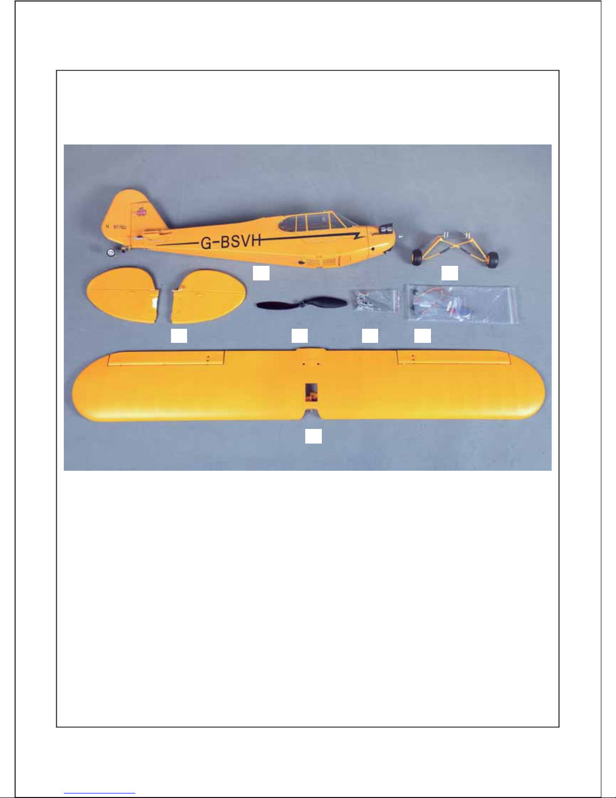
Kit Contents
2
3 5 6 7
41
1. The fuselage assembly (With the motor, the canopy, the electronic parts, ESC)
2. Main wing ( With all electric device installed)
3. Horizontal stabilizer with elevator joiner installed
4. landing gear set
5. Propeller
6. Spare parts bag
7. wires and screw driver
Page 5
3
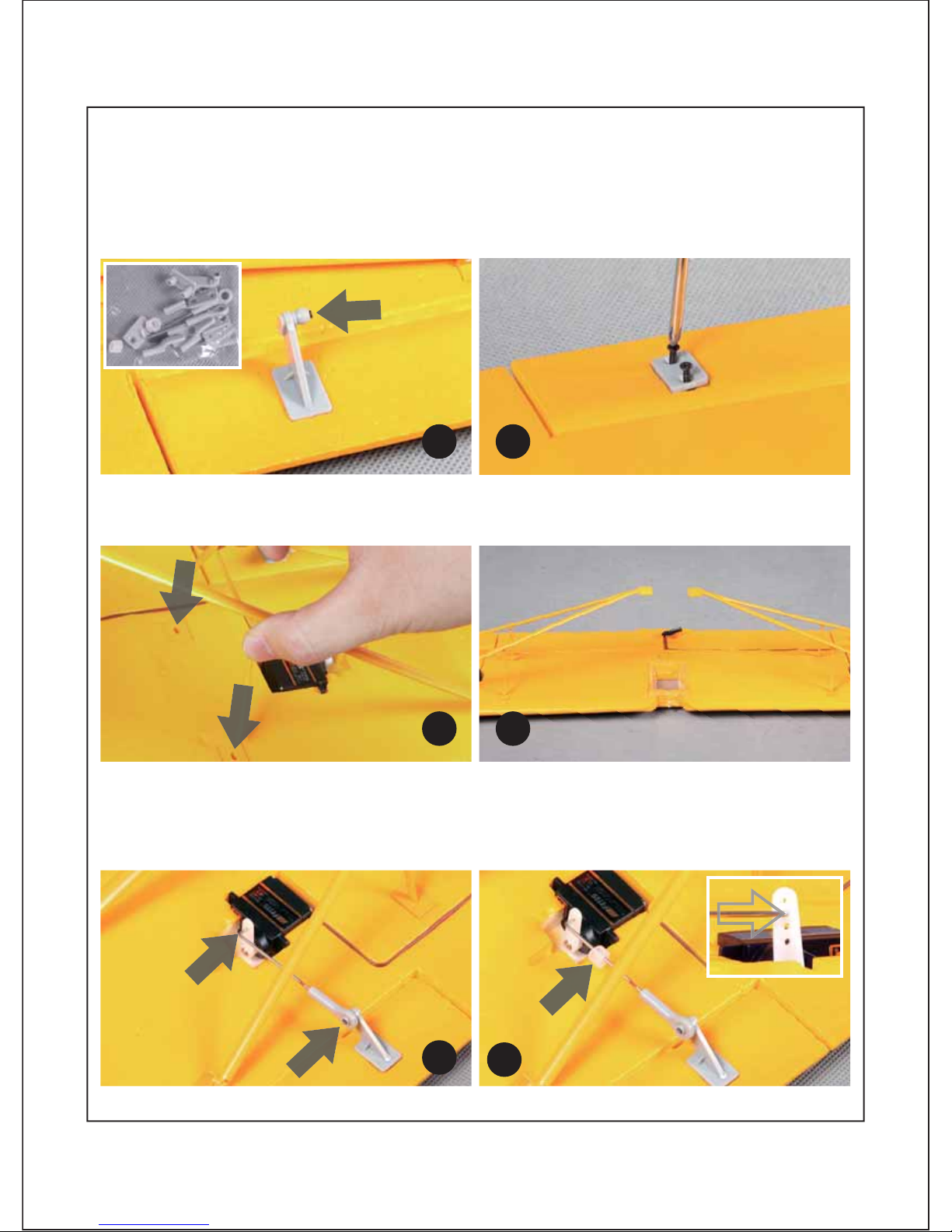
Fuselage/tail assembly
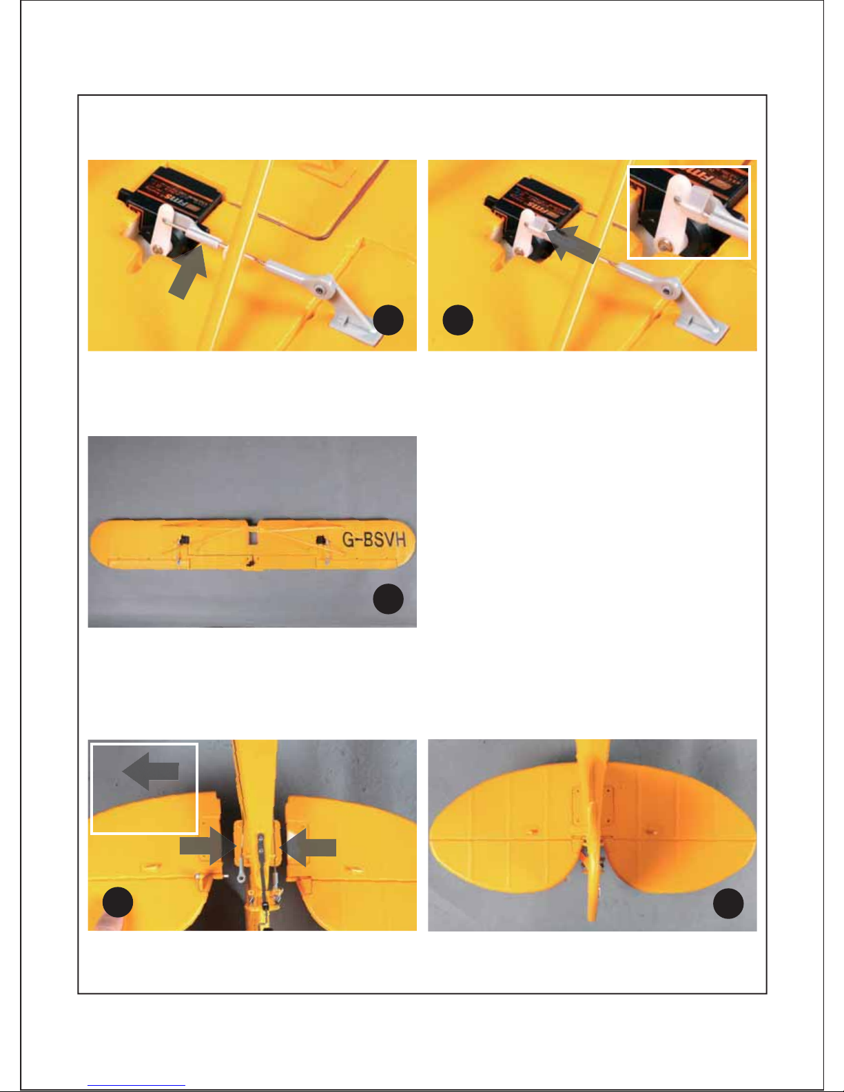
1.Place the ball-linked control horn on the aileron surface. Make sure that the orientation of the
ball-link is placed as shown on the picture below. (Fig.1)
2.Once aligned, secure the control horn on the aileron surface with the included screws.(Fig.2)
3.Attach the wing-brace to the attachment points on the wing. (Fig.3 and 4)
4.Connect the pushrods to the ball-links; make sure that the pushrod goes through the second hole
of the servo arm. Finish by attaching the plastic retainers so that the pushrod does not detach from
the servo arm. (Fig. 5-8)
Page 6
4
5.Repeat steps 1-4 for the opposing wing.(fig.9)
6.Insert the horizontal-stabilizer as shown in the picture below. Check that the control horn and
ball-link are located on the starboard horizontal stabilizer (right of the fuselage). (fig.10-11)
Page 7
5
3$;
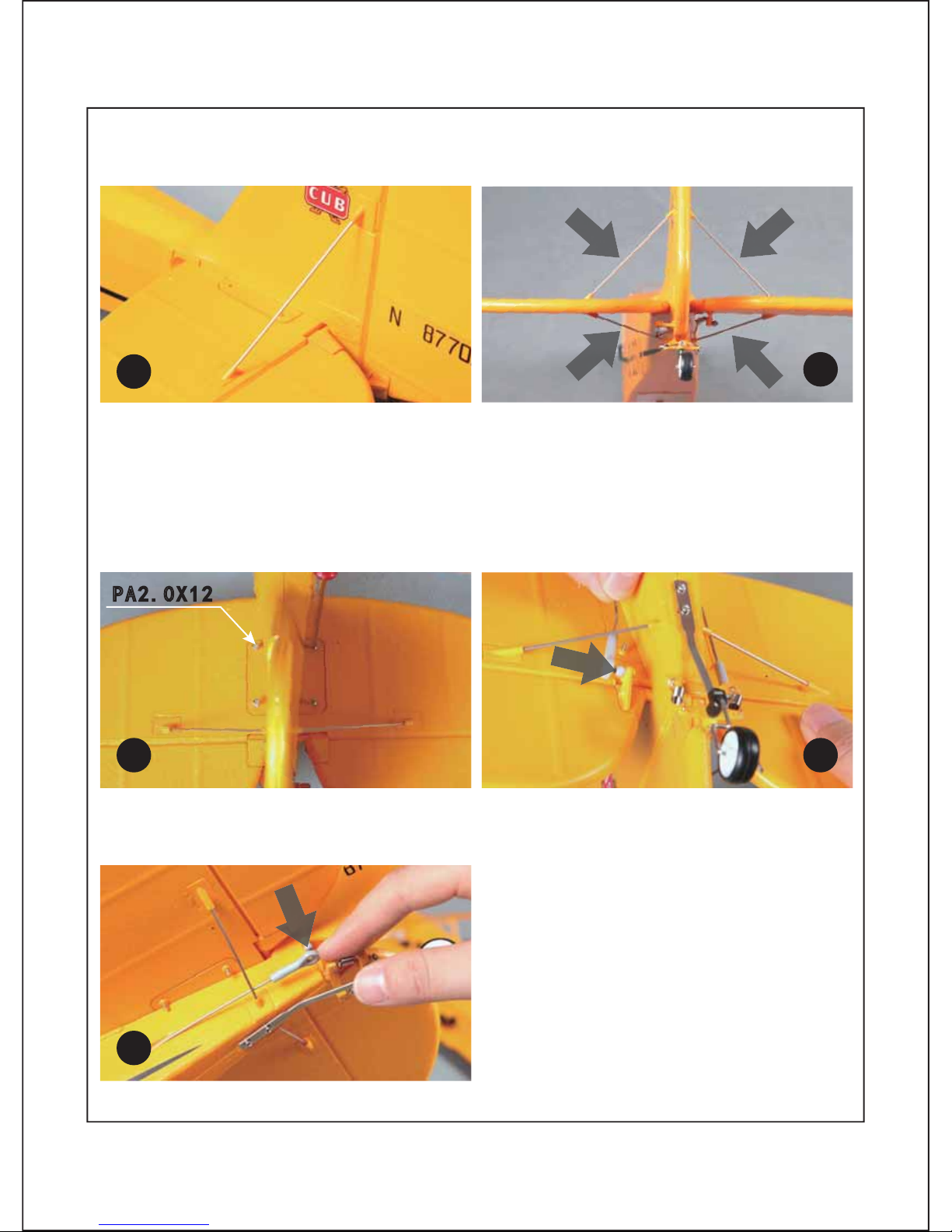
7.Install the braces that hold the horizontal stabilizer in place. (fig. 12-13)
9.Please secure the pushrod to the ball link while ensuring that the elevator surface is level with the
rest of the horizontal stabilizer; if not, please adjust the length of the linkage accordingly. (fig. 15)
8.Secure the horizontal stabilizer by attaching PA2.0x12 screws to the top of the horizontal stabilizer.
(fig.14)
10.Repeat step 9 for the rudder push rod and control horn. (fig. 16)
Page 8
6
30;
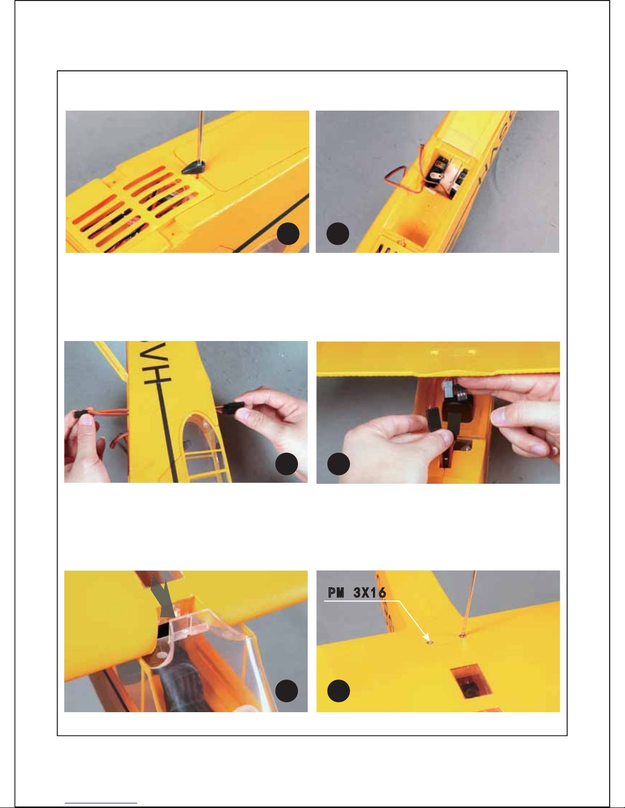
11.Open the electronics hatch by loosening the screw shown on the picture below (fig. 17-18)
14.Attach the wing to the fuselage by sliding the wing into the top of the clear plastic windshield.
(fig.21)
15.Attach the wing-bolt to the top of the fuselage. (fig.22) (PM3x16/2pcs)
12.Route the Y-harness into the electronics hatch (Sequence: CH1-Aileron, CH2-Elevator,
CH3-Throttle, CH4- Rudder); secure the electronics bay by tightening the screw (fig.19)
13.Connect the Y-harness with the 2 aileron servo leads on the wing.(fig.20)
Page 9
7
30;
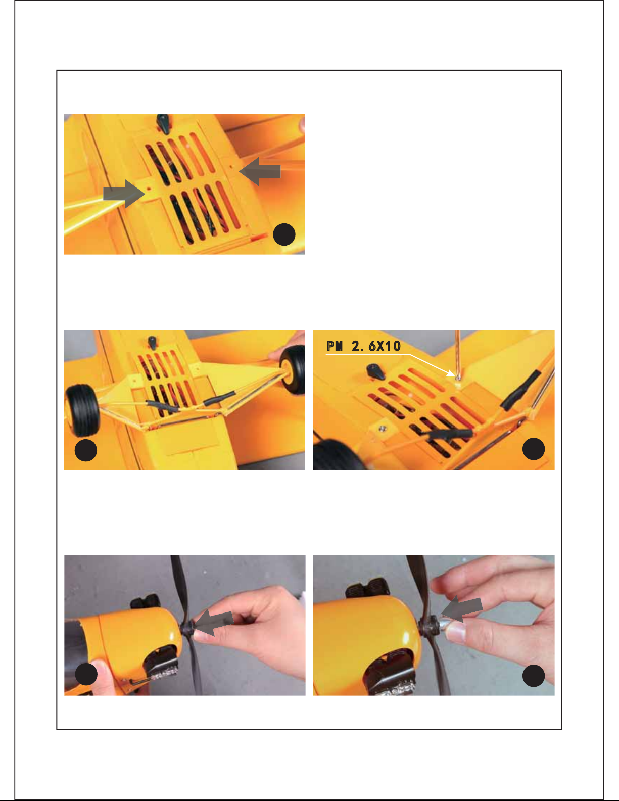
18.Insert the propeller onto the motor hub; make sure that the molded letters on the propellers face
outwards, and then attach and tighten the prop nut with the included screwdriver. (fig.26-28)
16.Align the wing-brace to the bottom of the fuselage. (fig.23)
17.Align and secure the landing gear to the hard points on the fuselage; secure the wing-brace to
the bottom of the fuselage. (fig. 24-25) (PA 2.6x10/2pcs)
Page 10

8
19.Your aircraft is now fully assembled.
Page 11

Page 12

Page 13

Page 14

12
for smooth control of your aircraft,always make small control moves. All directions are
described as if you were sitting in the air craft.
Tips:
1. Flying faster and slower: When your aircraft is stable in the air,push thethrottle stick up to
make the aircraft go faster,and pull the throttle stick back to slow down.The aircraft will climb
when the throttle is in creased.
2. bank right and left:Move the aileron stick right to make the aircraft bank right and move the
aileron stick left to bank left.
3. Elevator up and down:Push the elevator stick forward to make the aircaft go down and pull
the elevator stick back to go up.
Flight control
Yaw RightRudder: Yaw Left
Page 15

Assemble the plane
Check the C.G. (Center of Gravity)
13
Center of Gravity
When balancing your model , adjust the motor battery as necessary so the model is level or
slightly nose down. This the correct balance point for your model. After the first flights, The
CG position can be adjusted for your personal preference.
1. The recommended Center of Gravity (CG) location for your model is (45 mm) back from
the leading edge of the top main wing as shown with the battery pack installed.Mark the
location of the CG on top of the wing.
45mm
Page 16

14
Page 17

15
Page 18

Page 19

17
Spare parts list content
MR101-YEL Fuselage
MR102-YEL Main wing set
MR103-YEL Horizontal Stabilizer(one elevator)
MR104-YEL Stay Bar(one set)
MR105- Propeller
MR106- Canopy
MR107- Screws(one set)
FMS-Motor-KV1700 Brushless Motor
FMSSER9GP Servo
MR204-YEL Landing gear set
MR301-YEL Sticker
MR303-YEL Cowl
MR304 Motor Board
MR305 Propeller Nut
Note:All of the parts are painted with no decal applied.
MR302-YEL Motor Mount
FMS-ESC-20A Brushless ESC
Page 20

18
Spare parts list content
MR101-YEL MR102-YEL MR103-YEL
MR104YEL MR105 MR106
MR107 MR204-YEL MR301-YEL
MR302-YEL MR303-YEL MR304
Page 21

19
All instructions and warnings must be followed exactly. Mishandling of Li-Po Caution:
batteries can result in fire, personal injury, or property damage.
Battery warning:
By handling, charging or using the included Li-Po battery
you assume all risks associated with lithium batteries.
If at any time the batteries begin to swell, or balloon, discontinue use immediately!
Charging or dischargi
ng a swelling or ballooning battery can result in fire.
Always store the batteries at room temperature in a dry area to extend the life of
the battery. Always transport or temporarily store the battery in a temperature range of
40-120 F. Do not store battery or model in a car or in direct sunlight. If stored in a hot car,
o
the battery can be damaged or even catch fire.
Never use a Ni-Mh cha
rger. Failure to charge the battery with a compatible charger may
cause fire resulting in personal injury and property damage.
Never discharge Li-Po cells to below 3V.
Never leave charging batteries unattended.
Never charge damaged batteries.
The Battery Charger is designed to safely charge the Li-Po battery,
Charging the flight battery
When charging the battery, make certain the battery is on a heat-resistent surface, charge
the battery before assembly of the airplane. Install the fully charged battery to perform
control tests and binding.
Charging the Flight Battery
FMS-Motor-KV1700 FMSSER9GP
MR305
FMS-ESC-20A
Page 22

20
Page 23

2
21
Page 24

2
22
Page 25

2
23
Page 26

2
24
Page 27

2
25
Page 28

26
Page 29

www.fm sm odel.com
http://w ww .f aceb ook.com /
FMSmodel
 Loading...