

Page 1
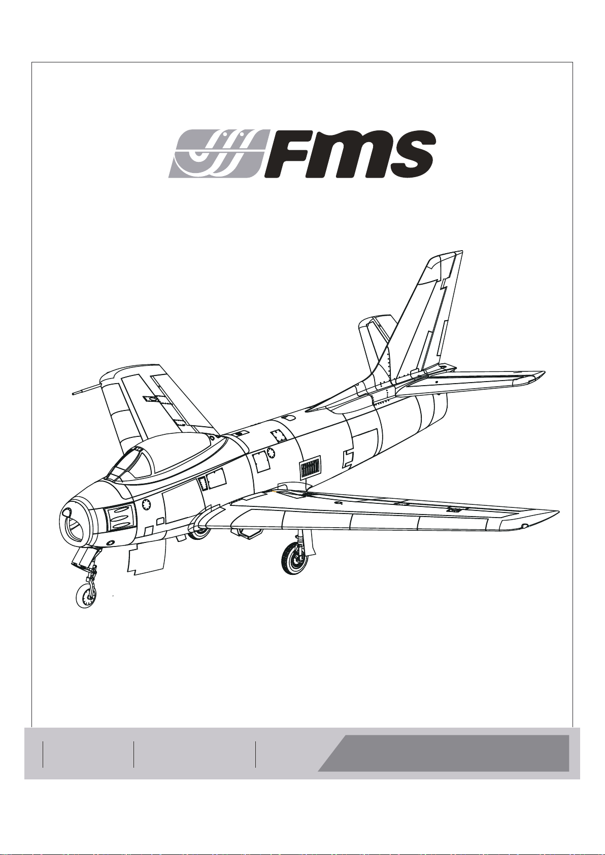
80mm F-86
MAN-G0244
REALISTIC RIGID STABLE
高还原度
高强度EPO泡沫 高安定性
Instruction Manual
Bedienungsanleitung
Manuel d’utilisation
操作手册
FMSMODEL.COM
Page 2
WARNING
WARNING: Read the ENTIRE instruction manual to become familiar with the features of the product before operating.
Failure to operate the product correctly can result in damage to the product,personal property and cause serious injury.
This is a sophisticated hobby product and NOT a toy. It must be operated with caution and common sense and failure to do so
could result in injury or damage to the product or other property. This product is not intended for use by children without direct
adult supervision.
This manual contains instructions for safety operation and maintenance. It is essential to read and follow all the instructions and
warnings in the manual prior to assembly, setup or use, in order to operate and avoid damage or serious injury.
p w
As the user of this product, you are solely responsible for operating in a manner that does not endanger yourself and others or
result in damage to the product or the property of others. This model is controlled by a radio signal subject to interference from
many sources outside your control. This interference can cause momentary loss of control so it is advisable to always keep a
safe distance in all directions around your model, as this margin will help avoid collisions or injury.
Age Recommendation: Not for children under 14 years. This is not a toy.
·Never operate your model with low transmitter batteries.
·Always operate your model in an open area away from cars, traffic or people.
·Avoid operating your model in the street where injury or damage can occur.
·Never operate the model in populated areas for any reason.
·Carefully follow the directions and warnings for this and any optional support equipment you use (chargers,rechargeable
battery packs, etc.)
·Keep all chemicals, small parts and anything electrical out of the reach of children.
·Moisture causes damage to electronics. Avoid water exposure to all equipment not specifically designed and protected for this
purpose.
·Never lick or any place of any your model in your mouth as it could cause serious injury or even death.
Lithium Polymer (Li-Po) Battery Warning
CAUTION: Always follow the manufacturer’s instructions for safe use and disposal of batteries. Fire, property
damage, or serious injury can result from the mishandling of Li-Po batteries.
By handling, charging or using a Li-Po Battery you assume all risks associated with lithium batteries.
If at any time the batteries begin to swell or balloon, discontinue use immediately!
Always store the batteries at room temperature in a dry area to extend the life of the battery. Always transport
or temporarily store the battery in a temperature range of 40-120F. Do not store the battery or model in a car or in direct sunlight.
If stored in a hot car, the battery can be damaged or even catch fire.
Never use a Ni-Mh Charger to charge Li-Po Batteries. Failure to charge the battery with a Li-Po compatible charger
may cause fire resulting in personal injury and property damage.
Never discharge Li-Po Cells below 3V.
Never leave charging batteries unattended.
Never charge damaged batteries.
Charging the Flight Battery Warning
Use a battery charger that is designed to safely charge the Li-Po Battery. Read the charger instructions care
fully before use. When charging the battery, make certain the battery is on a heat resistant surface. It is also highly
recommended to place the Li-Po Battery inside a fire resistant charging bag readily available at hobby shops or
online.
Page 3
E
N
Introduction
Background
After the end of World War II, the United States and the Soviet
Union brought back aviation experts, data, and equipment from
Germany to create their own jet fighter aircraft. The F-86 fighter
jet, nicknamed "Sabre," was a swept-wing jet fighter developed
by the United States. It was the first-generation jet fighter in
service with the U.S. Air Force, capable of air-to-air combat,
aerial interception, and bombing missions. It was also the
world's first fighter aircraft equipped with air-to-air missiles and
the first U.S. fighter aircraft with an ejection seat.
FMS model
Building upon their extensive experience in developing
remote-controlled model fighter aircraft, FMS has made
significant efforts to faithfully replicate the legendary and classic
F-86 "Sabre" with the product standard of "perfect appearance,
excellent performance." The model is filled with numerous
realistic details, such as operable landing-gear doors, retractable CNC-machined landing gear, movable airbrakes, wing
navigation lights (red on the left, green on the right), jet nozzle
navigation lights (one red, one white), and landing lights (white).
The static model-level exterior details have also been meticulously addressed, including fuel tanks, cockpit interior (molded
plastic parts), pitot tubes, and antennas.
Eight 13g all-metal digital servos control the ailerons, flaps,
rudder, and elevator, precisely executing input commands to
simulate the maneuverability of a fighter aircraft, making
maneuvers such as pitching, rolling, yawing, and flipping, easily
achievable. Three 9g semi-metal servos control the airbrakes,
which can increase the drag and reduce the speed of the
aircraft, and the operating of the front-landing gear door, which
when worked with the sequencer, can simulate the delayed
opening and closing of the front-landing gear door, ensuring
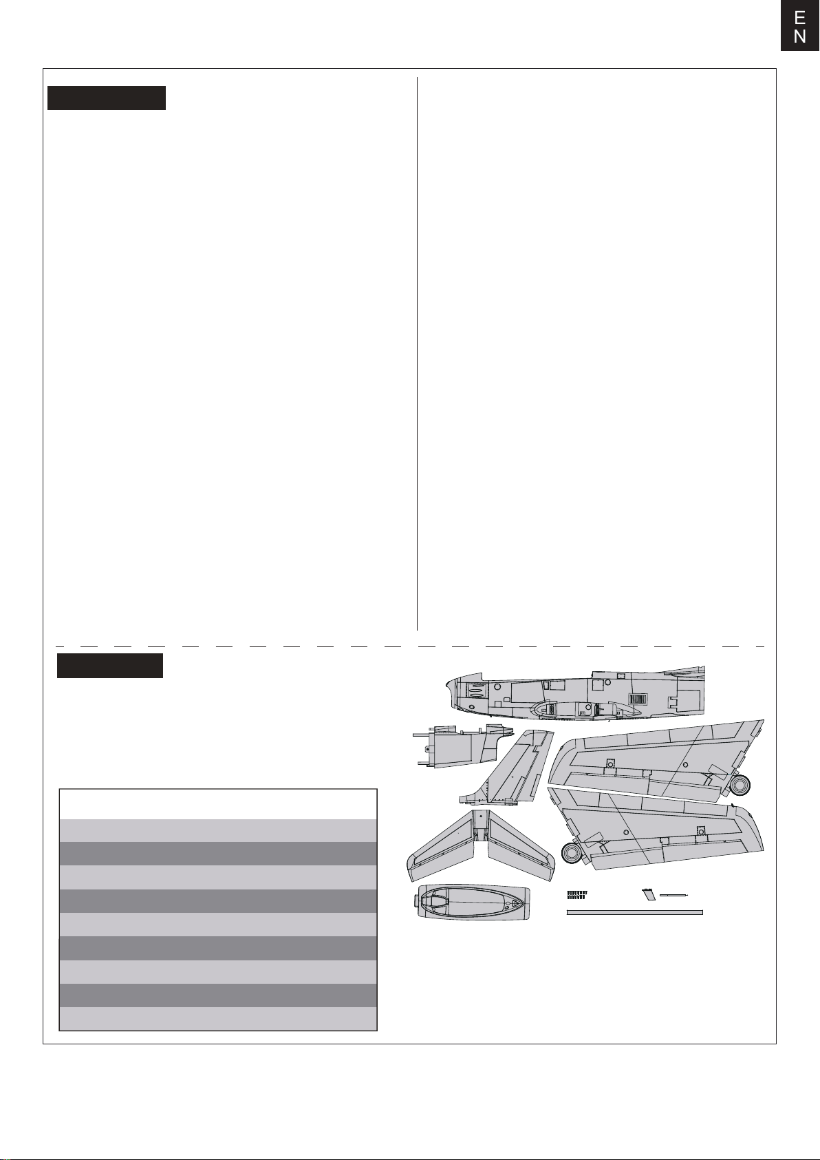
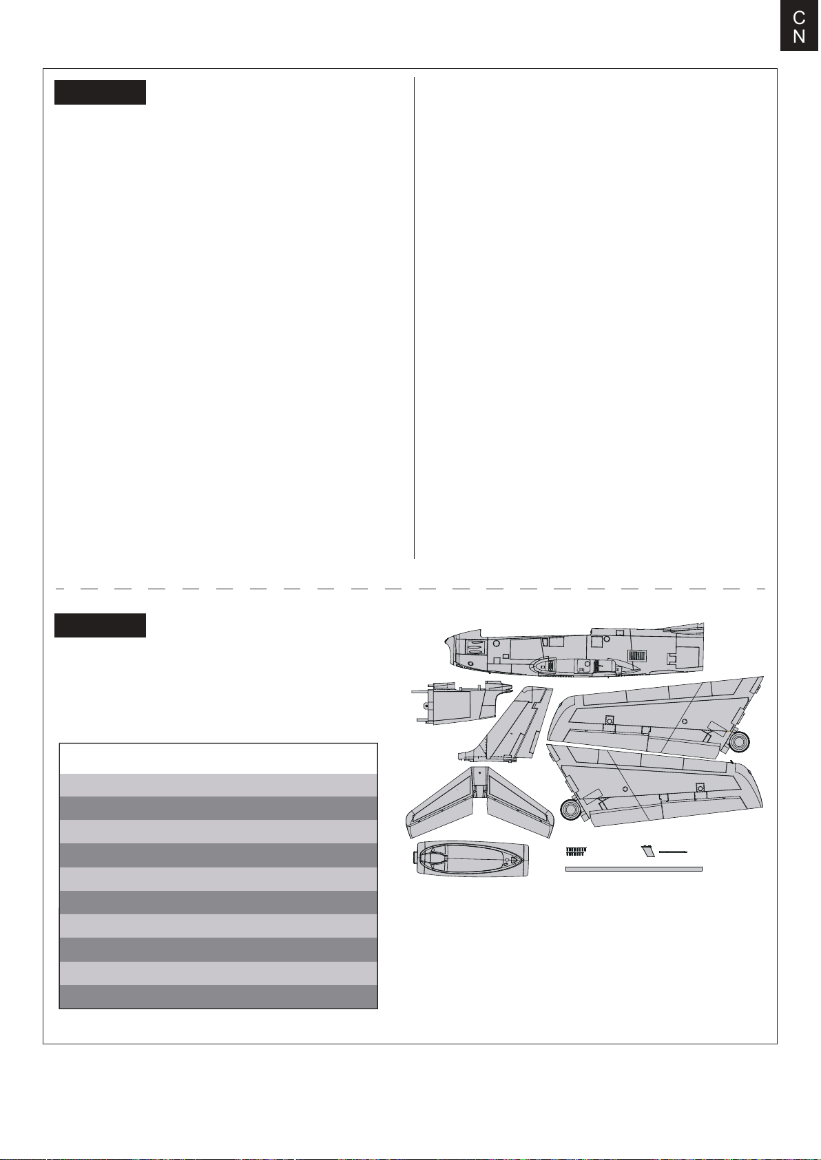
Kit contents
Before assembly, please inspect the contents of the kit. The
photo below details the contents of the kit with labels. If any
parts are missing or defective, please identify the name or
part number (refer to the spare parts list near the end of the
manual) then contact your local shop or email us: support
@fmsmodel.com.
synchronization with the movement of the landing gear
during the deployment or retraction process, ensuring safety
and smoothness.
The PNP configuration includes a 12-blade 80mm ducted
fan, a high-power 3665-KV2000 brushless inrunner motor,
and a 100A ESC (with a 5A switch-mode BEC), designed to
be used with a commonly available 6S 4000-5500mAh LiPo
battery (to be purchased separately). This high-performance
power and control system provides excellent performance,
longer flight times, and a more realistic turbine-like engine
sound for "combat" flying.
Additionally, key areas of the "Sabre" model, such as the
fuselage, wings, and tail, are reinforced with multiple
embedded strengthening tubes and reinforcement plates,
ensuring structural strength during extreme flight maneuvers. The two-piece design of the fuselage reduces packaging size by thirty percent, facilitating easy transport and
storage. The model is available in two classic schemes,
"THE HUFF" and "SKYBLAZERS," which are easily
recognizable in clear skies or overcast conditions.
Features:
1.Electronic configuration: 80mm 12-blade ducted fan,
3665-KV2000 brushless motor, high-performance 100A ESC,
8x 13g all-metal digital servos, 3x 9g semi-metal servos.
2.Rich in dynamic and static realistic details, such as operable
landing-gear doors, retractable CNC-machined landing gear set,
movable airbrakes, navigation lights, landing lights, fuel tanks,
scaled cockpit interior, etc.
3.CNC-machined shock-absorbed full-metal landing gear set
effectively countering hard landings.
4.Two-piece fuselage structure reducing packaging size by
thirty percent.
5.Realistic water-based paint finish, offering a high-quality
appearance.
A.
B.
C.
Specifications
Wing span:1220mm /48in
Overall length: 1165mm /46in
Flying weight: ~ 3050g
Motor size: 3665-KV2000
Wing load:95.3 g/dm² ( 0.18oz/in²)
Wing area: 32dm² ( 495.8 sq.in)
ESC: 100A
Servo: 13gX8,9gX3
Recommended battery: 22.2V 4000mAh-5500mAh 45c
D.
E.
F.G.H.
I.
A.Front fuselage
B.Rear fuselage
C.Main wing set
D.Vertical Stabilizer
E.Horizontal Stabilizer
F.Cockpit
G.Screw set(HKM3.0*10mm x 13)
H.Antenna and airspeed head
I.Wing spar
3
Page 4
E
N
Model assembly
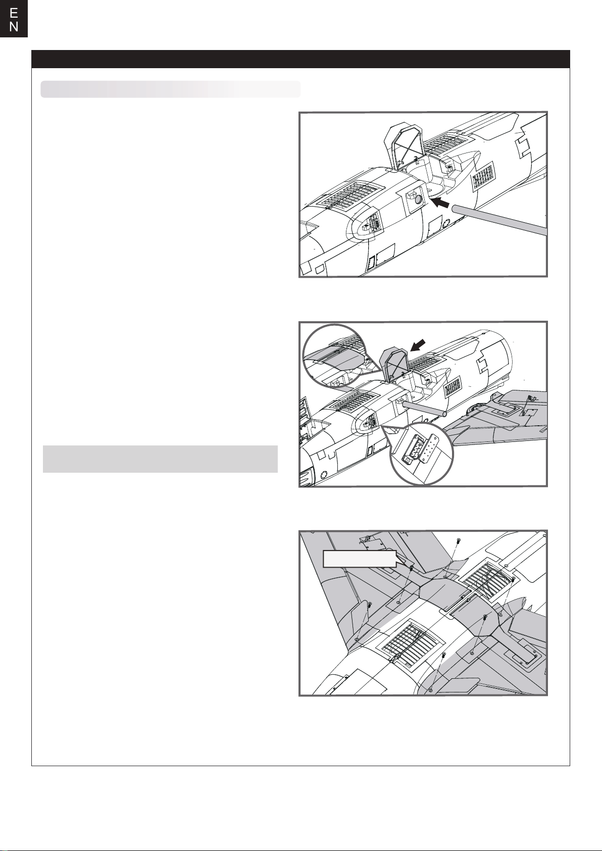
Main wing installation
1.Align and slide the wing spar into the fuselage.
2.Press the left and right door covers down to the bottom (i.e.
closed position) and attach the left and right wings with
landing gear to the fuselage.
NOTE:The connectors on both sides should be attached
precisely and firmly.
3.Secure the wings on the fuselage using the included
screws (HKM3.0*10mm x 6) as shown.
HKM3.0*10mm
4
Page 5
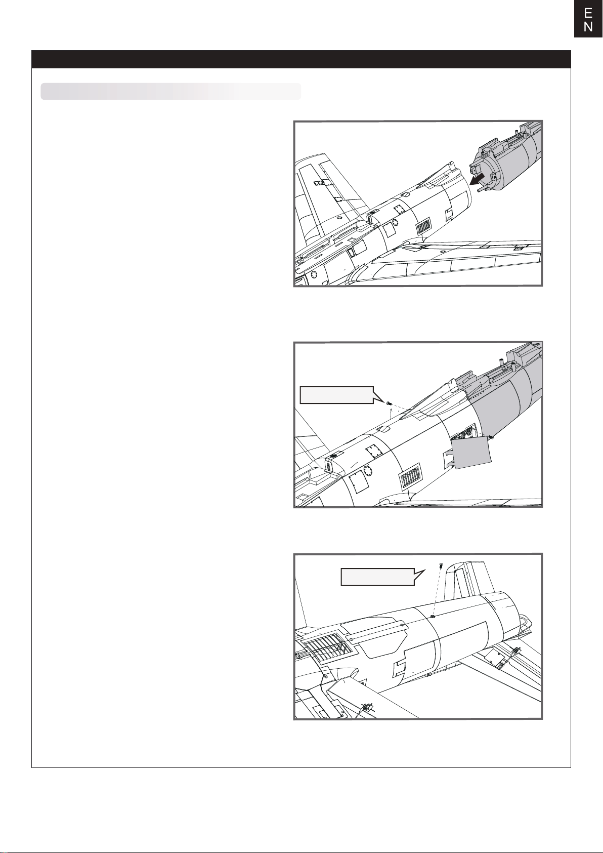
Model assembly
Rear fuselage installation
1.Thread the extension wire from front fuselage through
the rear fuselage trough, align and install the rear
fuselage to the rear of the front fuselage in the corresponding slot as shown.
E
N
2.Use the flap channel of the remote control to open the
airbrake and use the included screws (HKM3.0*10mm
x 2) to secure the rear fuselage horizontally into place.
3.With the bottom of the fuselage facing up, Secure the
front and rear fuselage using the included screws
(HKM3.0*10mm x 1) .
HKM3.0*10mm
HKM3.0*10mm
5
Page 6
E
N
Model assembly
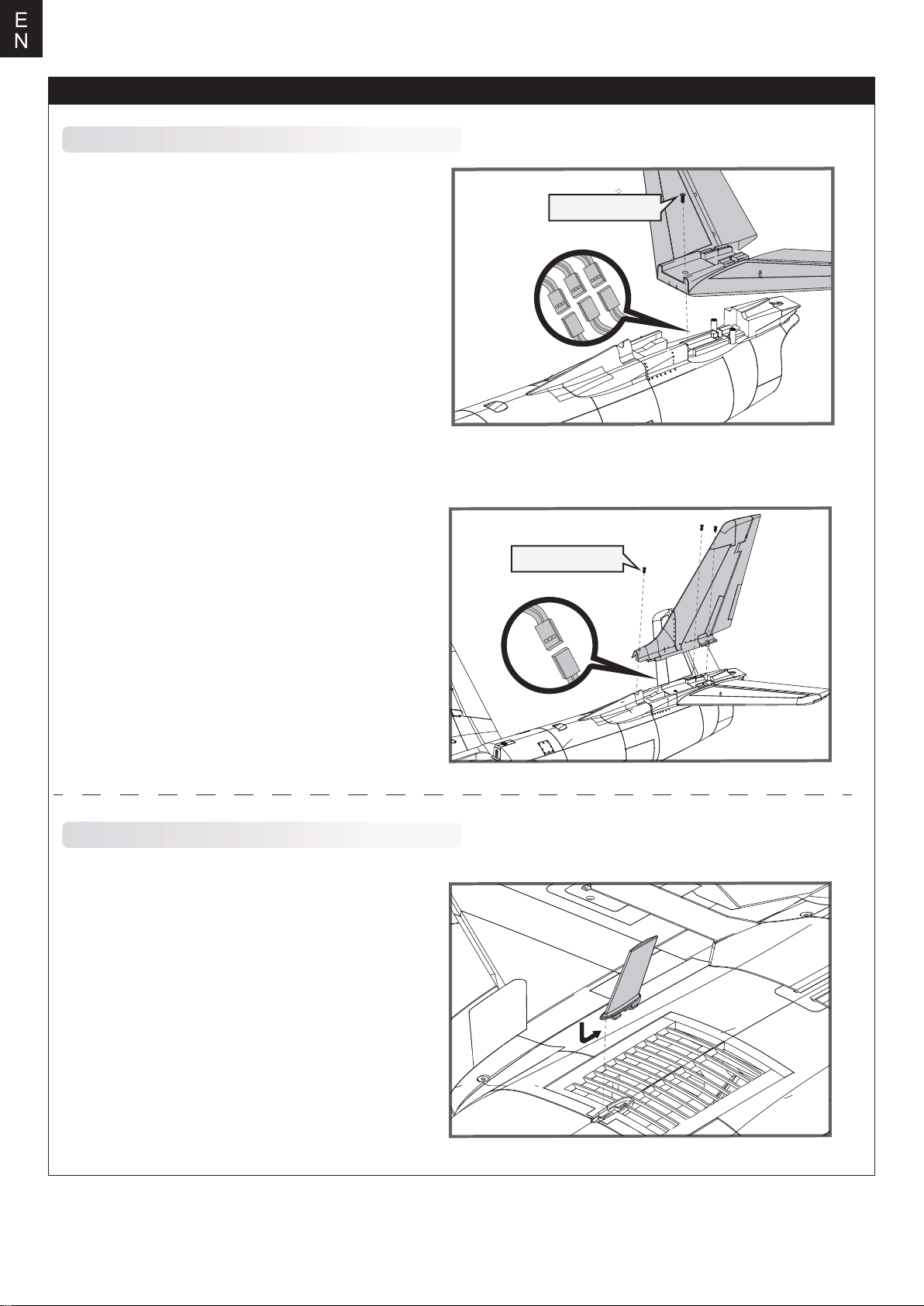
Vertical tail and horizontal tail installation
1.Align and connect the elevator servo plugs and LED
plugs to the servo extensions located within the
fuselage. Carefully insert the horizontal stabilizer to the
horizontal stabilizer slot of the fuselage and secure
using the included screws (HKM3.0*10mm x 1) .
HKM3.0*10mm
2.Align and connect the rudder servo plugs to the servo
extensions located within the fuselage. Carefully insert
the vertical stabilizer to the vertical stabilizer slot of the
fuselage and Secure it in place using the included
screws (HKM3.0*10mm x 3) .
Non-functional scale parts installation
1.Insert the non-functional scale antennas into the
corresponding slot at the bottom of fuselage as shown,
and slide it toward the tail to lock in place.
HKM3.0*10mm
6
Page 7
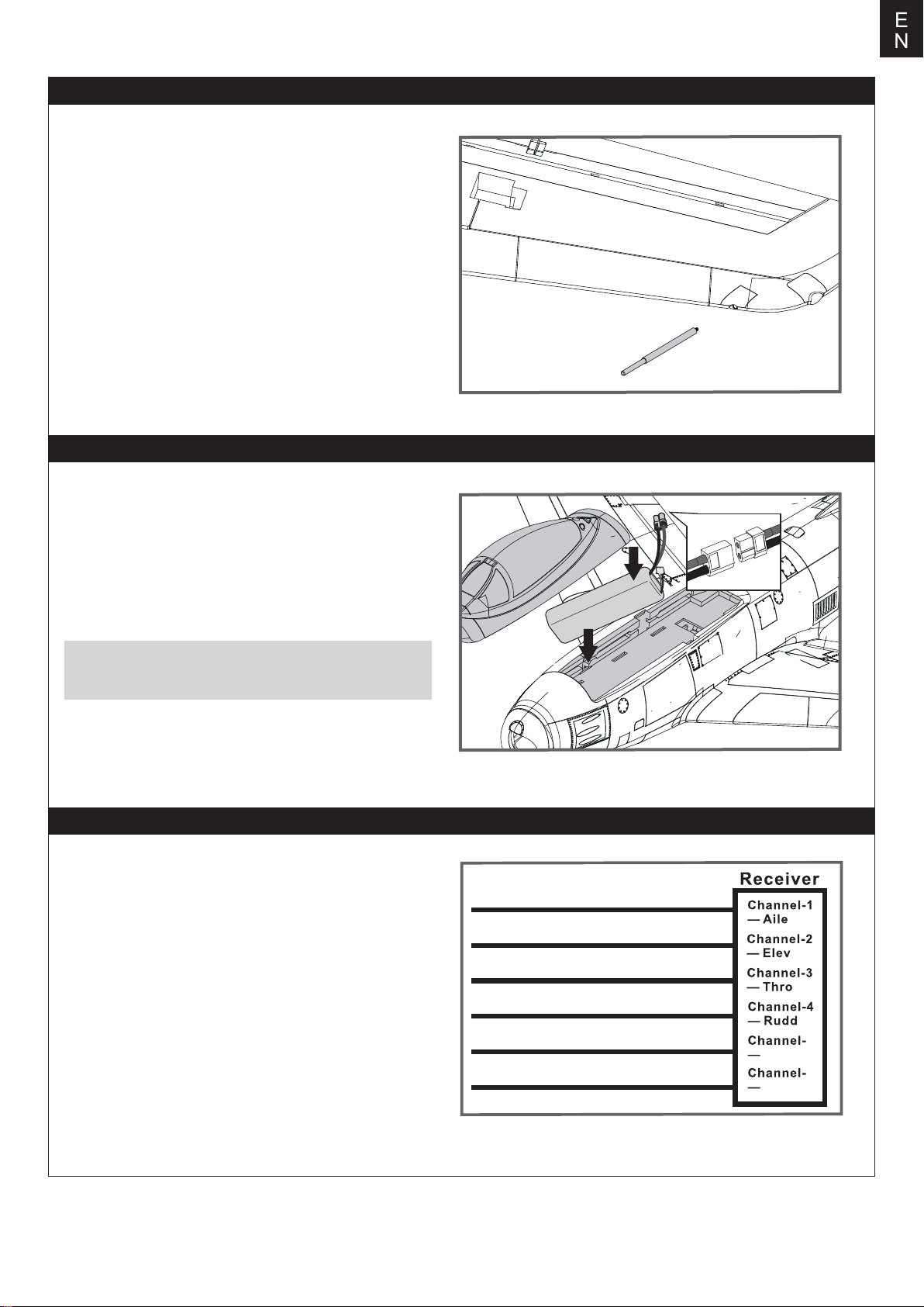
Model assembly
2.Insert the non-functional scale airspeed head into the
wingtip slot.
Battery installation
E
N
1.Pull back on the latch and remove the battery hatch.
2.Apply the hook tape to the cable end of the battery.
3.Slide the full charged battery into the battery compartment wtith the power supply cable toward the rear end of
the plane.
Note: The center of gravity can be adjusted by moving
the battery forward or aft. Having the correct center of
gravity is critical to achieving proper flight characteristics.
Battery compartment size:200*68*45mm
Receiver diagram
The cables from the servo connector board should be connected to your receiver in the order shown. Note that the
LEDs can be powered by any spare channel on the receiver. Tuck the wire leads into the recessed cavity towards
the rear of the battery hatch.
Gear
EIevator
Throttle
1
2
3
7
Rudder
Gear
Spare
4
5
6
5
Gear
6
Spare
Page 8
E
N
Get your model ready to fly
Important ESC and model information
The ESC included with the model has a safe start. If the motor battery is connected to the ESC and the throttle stick is not in
1.
the low throttle or off position, the motor will not start until the throttle stick is moved to the low throttle or off position. Once the
throttle stick is moved to the low throttle or off position, the motor will emit a series of beeps. Several beeps with the same tune
means the ESC has detected the cells of the battery. The count of the beeps equals the cells of the battery. The motor is now
armed and will start when the throttle is moved.
The motor and ESC come pre-connected and the motor rotation should be correct. If for any reason the motor is rotating in the
2.
wrong direction, simply reverse two of the three motor wires to change the direction of rotation.
The motor has an optional brake setting. The ESC comes with brake switched off and we recommend that the model be flown
3.
with the brake off. However, the brake could be accidentally switched on if the motor battery is connected to the ESC while the
throttle stick is set at full throttle. To switch the brake off, move the throttle stick to full throttle and plug in the motor battery. The
motor will beep one time. Move the throttle stick to low throttle or the off position. The motor is ready to run and the brake will
be switched off.
4.
Battery Selection and Installation. We recommend the
battery must be at least a 22.2V 4000-5500mAh 45C battery. Your battery should be approximately the same capacity, dimen
sion and weight as the 22.2V 4000-5500mAh 45C Li-Po battery to fit the fuselage without changing the center of gravity signifi
cantly.
22.2V 4000-5500mAh 45C Li-Po battery. If using another battery, the
Get your model ready to fly
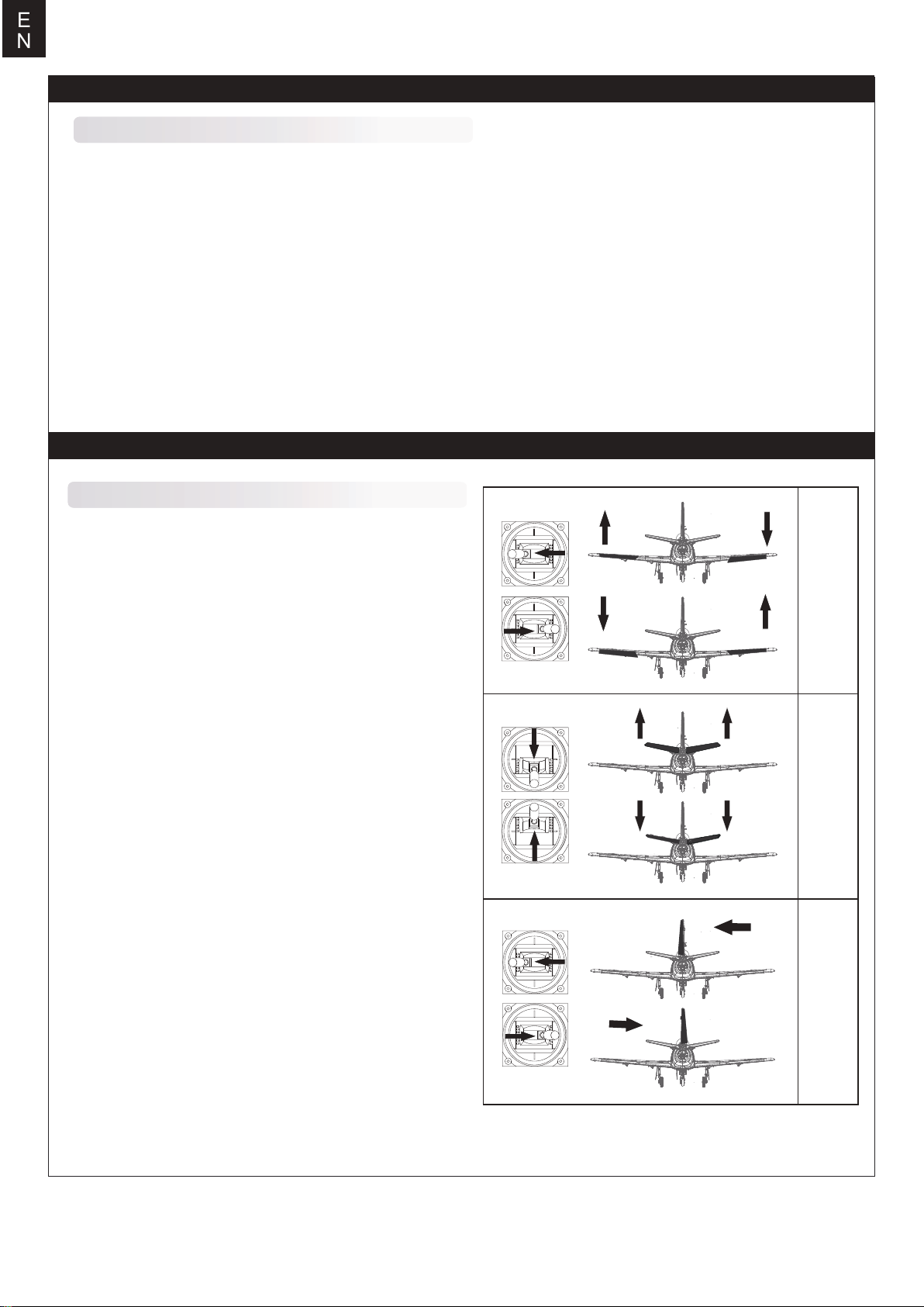
Transmitter and model setup
Before getting started, bind your receiver with your transmitter.
Please refer to your transmitter manual for proper operation.
CAUTION: To prevent personal injury, DO NOT install the propel
ler assembly onto the motor shaft while testing the control surfac
es. DO NOT arm the ESC and do not turn on the transmitter until
the Transmitter Manual instructs you to do so.
Tips: Make sure all control sticks on your radio are in the neutral
position (rudder, elevator, ailerons) and the throttle is in the OFF
position. Make sure both ailerons move up and down (travel) the
same amount. This model tracks well when the left and right
ailerons travel the same amount in response to the control stick.
Move the controls on the transmitter to make sure the aircraft
control surface moves correctly. See diagrams right.
-
-
Bank left
Aileron
Bank right
Climb
Elevator
Descend
Steer left
Steering Rudder
8
Steer right
Page 9
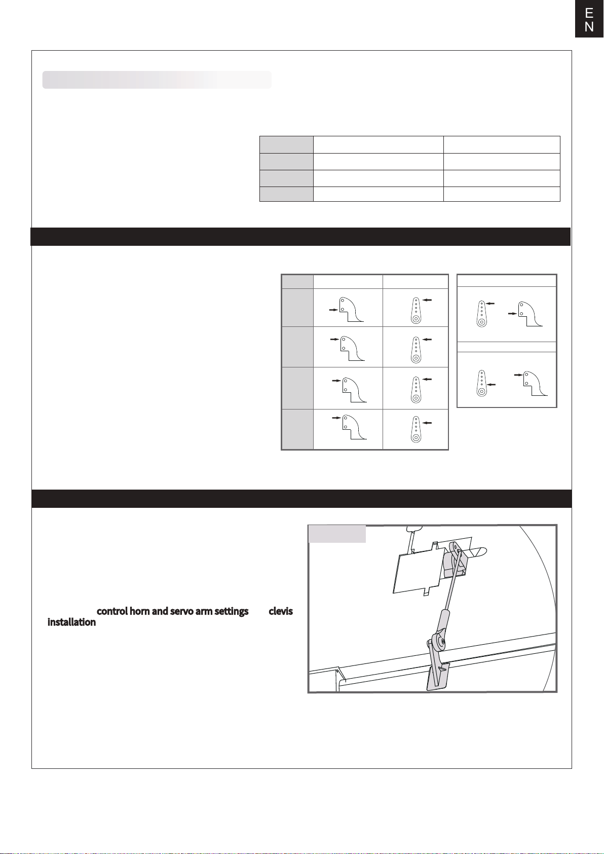
Control throws
The suggested control throw setting for this airplane are as follows (dual rate setting):
High Rate Low Rate
Tips: On the first flight, fly the model in low rate.
The first time you use high rates,be sure to fly at
low to medium speeds. High rate, as listed, is
only for EXTREME maneuvering.
Elevator
Aileron
Rudder
16mm up / down 12mm up / down
14mm up / down
14mm left / right
Control horn and servo arm settings
E
N
10mm up / down
10mm left / right
The table shows the factory settings for the control horns
and servo arms. Fly the aircraft at the factory settings
before making changes.
After flying, you may choose to adjust the linkage positions
for the desired control response.
Linkage rods installation
Before installing the main wing, horizontal tail and vertical
tail, the linkage rods for ailerons, flaps, elevators and
rudder should be installed in advance.
Make sure the servos are in neutral position. Attach the
“Z” bend end of aileron, flap, elevator and rudder linkage
rods to the corresponding holes in the aileron, flap, elevator
and rudder control arms from the outside as shown (Please
refer to the control horn and servo arm settings and clevis
installation sections in manual ). And then install the ball
buckleat the other end of the linkage rods to ball head at
each control horn on control surfaces.
ElevatorRudderAilerons
Flaps
ball head
Horns Arms
More control throw
Less control throw
9
Page 10
E
N
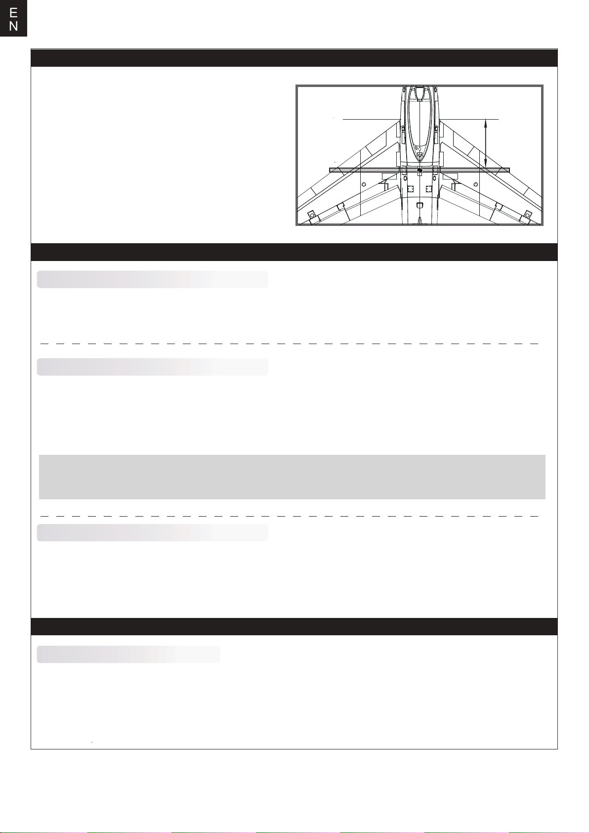
Check the C.G. (Center of gravity)
When balancing your model, adjust the battery as necessary
so the model is level or slightly nose down. This is the correct
balance point for your model. After the first flight, the CG
position can be adjusted for your personal preference.
1. The recommended Center of Gravity (CG) location for your
modelis(180-190mm)from the leading edge of the main wing
(as shown) with the battery pack installed. Mark the location
of the CG on top of the wing.
2. When balancing your model, support the plane at the marks
made on the bottom of the main wing with your fingers or a
commercially available balancing stand. This is the correct
balance point for your model. Make sure the model is assembled
and ready for flight before balancing.
Before flying the model
Find a suitable flying site
Find a flying site clear of buildings, trees, power lines and other obstructions. Until you know how much area will be required and
have mastered flying your plane in confined spaces, choose a site which is at least the size of two to three football fields - a flying
field specifically for R/C planes is best. Never fly near people - especially children, who can wander unpredictably
180-190mm
Perform the range check for your plane
As a precaution, an operational ground range test should be performed before the first flight each time you go out.
Performing a range test is a good way to detect problems that could cause loss of control such as low batteries, defective
or damaged radio components, or radio interference. This usually requires an assistant and should be done at the actual
flying site you will be using.
First turn on the transmitter, then install a fully-charged battery into the fuselage. Connect the battery and install the hatch.
Remember, use care not to bump the throttle stick. Otherwise, the propeller/fan will turn and possibly cause damage or injury
Note: Please refer to your Transmitter Manual that came with your radio control system to perform a ground range check. If the
controls are not working correctly or if anything seems wrong, do not fly the model until you correct the problem. Make
certain all the servo wires are securely connected to the receiver and the transmitter batteries have a good connection.
Monitor your flight time
Monitor and limit your flight time using a timer (such as on a wristwatch or in your transmitter if available). When the
batteries are getting low you will usually notice a performance drop before the ESC cuts off motor power, so when the plane starts
flying slower you should land. Often (but not always) power can be briefly restored after the motor cuts off by holding the throttle stick
all the way down for a few seconds.
To avoid an unexpected dead-stick landing on your first flight, set your timer to a conservative 4 minutes. When your alarm sounds
you should land right away.
Flying course
Take off
While applying power, slowly steer to keep the model straight.The model should accelerate quickly.
As the model gains flightspeed you will want to climb at a steady and even rate. It will climb out at a nice angle of attack (AOA).
10
Page 11
E
N
Flying
Always choose a wide-open space for flying your plane. It is
ideal for you to fly at a sanctioned flying field. If you are not
flying at an approved site always avoid flying near houses,
trees, wires and buildings. You should also be careful to avoid
flying in areas where there are many people, such as busy
parks, schoolyards, or soccer fields. Consult laws and
ordinances before choosing a location to fly your aircraft. After
takeoff, gain some altitude. Climb to a safe height before trying
technical manoeuvres, including high speed passes, inverted
flight, loops, and point rolls.
Maintenance
Repairs to the foam should be made with foam safe adhesives
such as hot glue, foam safe CA, and 5min epoxy. When parts
are not repairable, see the Spare Parts List for ordering by item
number.
Always check to make sure all screws on the aircraft are
tightened. Pay special attention to make sure the spinner is
firmly in place before every flight.
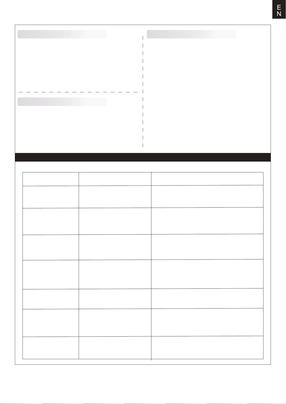
Trouble shooting
Landing
Land the model when you hear the motor pulsing (LVC) or if
you notice a reduction in power. If using a transmitter with a
timer, set the timer so you have enough flight time to make
several landing approaches.
The model’s three point landing gear allows the model to land on
hard surfaces. Align model directly into the wind and fly down to
the ground. Fly the airplane down to the ground using 1/4-1/3
throttle to keep enough energy for proper flare. Before the model
touches down, always fully decrease the throttle to avoid
damaging the propeller or other components. The key to a great
landing is to manage the power and elevator all the way to the
ground and set down lightly on the main landing gear. After a
few flights you will find the model can be set downlightlyon the
mains and you can hold the nose wheel off balancing themodel
on the mains until it slows and gently settles the nose.
Problem Possible Cause Solution
Aircraft will not respond to
the throttlebut responds to
other controls.
Extra propeller noise or
extra vibration.
Reduced flight time or
aircraft underpowered.
Control surface does not
move, or is slow to respond
to control inputs.
Controls reversed.
-Motor loses power
-Motor power pulses then
motor loses power.
-ESC is not armed.
-Throttle channel is reversed.
-Damaged spinner, propeller,
motor or motor mount.
-Loose propeller and spinner parts.
-Propellor installed backwards.
-Flight battery charge is low.
-propeller installed backward.
-Flight battery damaged.
-Control surface, control horn,
linkage or servo damage.
-Wire damaged or connections
loose.
Channels are reversed in the
transmitter.
-Damage to motor, or battery.
-Loss of power to aircraft.
-ESC uses default soft Low Voltage
Cutoff(LVC).
-Lower throttle stick and throttle trim to lowest settings.
-Reverse throttle channel on transmitter.
-Replace damaged parts.
-Tighten parts for propeller adapter, propeller and spinner.
-Remove and install propeller correctly.
-Completely recharge flight battery.
-Replace flight battery and follow flight battery
instructions.
-Replace or repair damaged parts and adjust controls.
-Do a check of connections for loose wiring.
Do the control direction test and adjust controls for
aircraft and transmitter.
-Do a check of batteries, transmitter, receiver, ESC, motor
and wiring for damage(replace as needed).
-Land aircraft immediately and recharge flight battery.
LED on receiver flashes
slowly.
Power loss to receiver.
-Check connection from ESC to receiver.
-Check servos for damage.
-Check linkages for binding.
11
Page 12
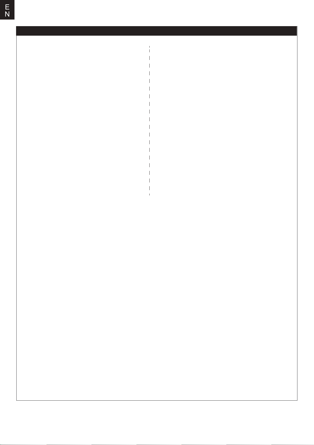
Spare parts list content
FMSEO101
FMSEO102
FMSEO103
FMSEO104
FMSEO105
FMSEO106
FMSEO107
FMSEO108
FMSEO109
FMSEO110
FMSEO111
FMSEO112
FMSEO113
FMSEO114
FMSEO115
FMSEO116
FMSEO117
FMSEO118
FMSEO119
FMSEO120
FMSEO121
FMSEO122
FMSEO123
FMSSDX006
Fuselage(for The Huff)
Main wing set(for The Huff)
Horizontal stabilizer(for The Huff)
Vertical Stabilizer(for The Huff)
Cowl
Canopy
Wing bolt plastic set
Wing Pipe
Control horn
Front landing gear
Main landing gear
Front landing gear system
Main landing gear system
air grill on the fuselage
Linkage Rods
Sticker(for The Huff)
Screw Set
Front landing gear cover
Main landing gear cover
Deceleration Hatch
Lamp cover
LED set
Airspeed Head(for The Huff)
80mm Single Duct
PRKVX2000-1
PRESC014
FMSCON012
FMSREX069
FMSREX070
PRSER003
PRSER004
PRSER005
FMSSER015
FMSSER016
FMSEO101SB
FMSEO102SB
FMSEO103SB
FMSEO104SB
FMSEO116SB
FMSEO123SB
Motor 3665-KV2000
100A ESC
Multi-connector set
E-retract
E-retract
Predator 13g digital metal gear servo positive
with 300mm wire
Predator 13g digital metal gear servo positive
with 460mm wire
Predator 13g digital metal gear servo reverse
with 460mm wire
9g digital metal gear servo positive with
460mm wire
9g digital metal gear servo reverse with
460mm wire
Fuselage(for Sky Blazer)
Main wing set(for Sky Blazer)
Horizontal stabilizer(for Sky Blazer)
Vertical Stabilizer(for Sky Blazer)
Sticker(for Sky Blazer)
Airspeed Head(for Sky Blazer)
Visit our website: www.fmshobby.com to see photo of this product. Enter the key word "ESC" in the search bar for the
stock ESC instruction manual.
12
Page 13
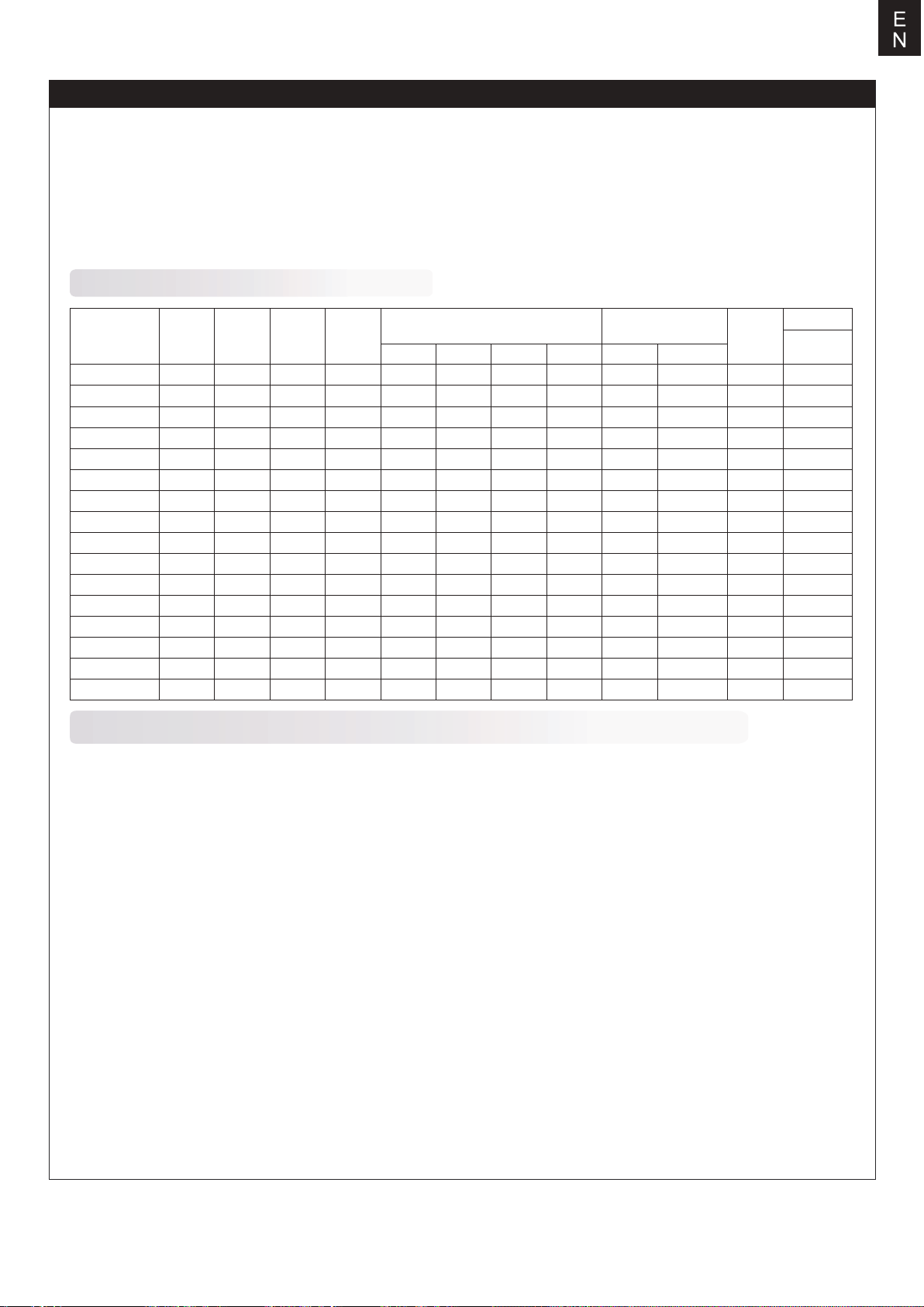
User Manual of Brushless Speed Controller
Thanks for purchasing our Electronic Speed Controller (ESC). High power system for RC model is very dangerous,
please read this manual carefully. In that we have no control over the correct use, installation, application, or
maintenance of our products,no liability shall be assumed nor accepted for any damages, losses or costs resulting
from the use of the product. Any claims arising from the operating, failure or malfunctioning etc. will be denied. We
assume no liability for personal injury, property damage or consequential damages resulting from our product or
our workmanship. As far as is legally permitted, the obligation to compensation is limited to the invoice amount of
the affected product.
Specifications
Weight
L*W*H
(mm)
32*12*4.5
38*18*6
38*18*7
48*22.5*6
42*25*8
68*25*8
68*25*8
65*25*12
65*29*10
77*35*14
86*38*12
86*38*12
86*38*12
85*36*9
85*36*9
85*36*9
Model
6A
12A
12AE
15A
20A
30A
40A
40A-UBEC
50A-UBEC
60A-UBEC
60A-UBEC
80A-UBEC
80A-UBEC
80A-BEC
80Ax2+UBE
100A ESC
Cont
Current
6A
12A
12A
15A
20A
30A
40A
40A
50A
60A
60A
80A
80A
80A
80A
100A
Burst
Current
(≤10)
8A
15A
15A
20A
25A
40A
55A
55A
65A
80A
80A
100A
100A
100A
100A
120A
BEC
Mode
Linear
Linear
Linear
Linear
Linear
Linear
Linear
Switch
Switch
Switch
N/A
Switch
N/A
Switch
Switch
Switch
BEC
Output
5V/0.8A
5V/1A
5V/2A
5V/2A
5V/2A
5V/2A
5V/3A
5V/3A
5V/5A
5V/5A
N/A
5V/5A
N/A
5V/7A
5V/10A
5V/7A
BEC Output Capability Battery Cell
2S Lipo 3S Lipo 4S Lipo 6S Lipo Lipo NiMH
3servos
3servos
5servos
5servos
5servos
5servos
5servos
5servos
8servos
8servos
8servos
2servos
4servos
4servos
4servos
4servos
4servos
5servos
8servos
8servos
8servos
5servos
6servos
6servos
6servos
6servos
6servos
6servos
2S
2-3S
2-3S
2-3S
2-3S
2-3S
2-3S
2-4S
2-4S
2-6S
2-6S
2-6S
2-6S
3-6S
3-6S
3-6S
5-6 cells
5-9 cells
5-9 cells
5-9 cells
5-9 cells
5-9 cells
5-9 cells
5-12 cells
5-12 cells
5-18 cells
5-18 cells
5-18 cells
5-18 cells
5-18 cells
5-18 cells
5-18 cells
Weight
5.5
9g
10g
16.5g
19g
37g
39g
43g
41g
63g
60g
82g
79g
79g
175g
92g
Programmable Items (The option written in bold font is the default setting)
1. Brake Setting:Enabled / Disabled
2. Battery Type:Lipo / NiMH
3. Low Voltage Protection Mode(Cut-Off Mode): Soft Cut-Off (Gradually reduce the output power) /Cut-Off
(Immediately stop the output power).
4. Low Voltage Protection Threshold(Cut-Off Threshold):Low / Medium / High
1) For lithium battery, the battery cell number is calculated automatically. Low / medium / high cutoff voltage for
each cell is 2.85V/3.15V/3.3V. For example: For a 3S Lipo, when "Medium" cutoff threshold is set, the cut-off
voltage will be:3.15*3=9.45V.
2) For NiMH battery, low / medium / high cutoff voltages are 0%/50%/65% of the startup voltage (i.e. the initial
voltage of battery pack), and 0% means the low voltage cut-off function is disabled. For example: For a 6 cells
NiMH battery, fully charged voltage is 1.44*6=8.64V, when "Medium"cut-off threshold is set, the cut-off voltage
will be: 8.64*50%=4.32V.
5. Startup Mode:Normal /Soft /Super-Soft (300ms / 1.5s / 3s)
a) Normal mode is suitable for fixed-wing aircraft. Soft or Super-soft modes are suitable for helicopters. The
initial acceleration of the Soft and Super-Soft modes are slower, it takes 1.5 second for Soft startup or 3 seconds
for Super-Soft startup from initial throttle advance to full throttle. If the throttle is completely closed (throttle stick
moved to bottom position) and opened again (throttle stick moved to top position) within 3 seconds after the first
startup, the re-startup will be temporarily changed to normal mode to get rid of the chance of a crash caused by
slow throttle response. This special design is suitable for aerobatic flight when quick throttle response is needed.
6. Timing:Low / Medium / High,( 3.75°/15°/26.25°) Usually, low timing is suitable for most motors. To get higher
speed, High timing value can be chosen.
13
Page 14
User Manual of Brushless Speed Controller
Begin To Use Your New ESC
IMPORTANT! Because different transmitter has different throttle range, please calibrate throttle range
before flying.
Throttle range setting (Throttle range should be reset whenever a new transmitter is being used)
1.Switch on the transmi t ter, move throttle stick to the top position.
2.Connect battery pack to the ESC, and wait for about 2 seconds.
3.The "Beep-Beep-" tone should be emitted, means the top point of throttle range has been confirmed.
4.Move throttle stick to the bottom position, several "beep-" tones should be emitted to present the amount of
battery cells.
5.A long "Beep-" tone should be emitted, means the lowest point of throttle range has been correctly confirmed.
Normal startup procedure
1.Move throttle stick to bottom position and then switch on transmitter.
2Connect battery pack to ESC, special tone like "♪ 123" means power supply is OK.
3.Several "beep-" tones should be emitted to present the amount of lithium battery cells.
4.When self-test is finished, a long"beep-----" tone should be emitted.
5.Move throttle stick upwards to go flying.
Protection Function
1. Start up failure protection: If the motor fails to start within 2 seconds of throttle application, the ESC will cut-off
the output power. In this case, the throttle stick MUST be moved to the bottom again to restart the motor. (Such a
situation happens in the following cases: The connection between ESC and motor is not reliable, the propeller or
the motor is blocked, the gearbox is damaged, etc.)
2. Over-heat protection: When the temperature of the ESC is over about 110 Celsius degrees, the ESC will reduce
the output power.
3.Throttle signal loss protection: The ESC will reduce the output power if throttle signal is lost for 1 second, further
loss for 2 seconds will cause the output to be cut-off completely.
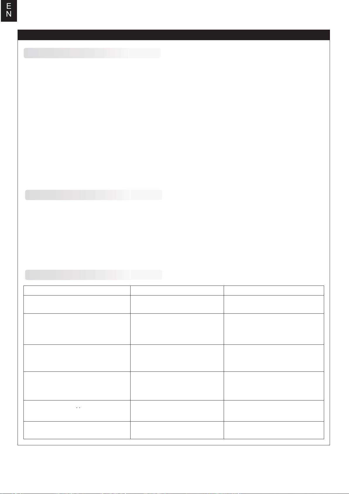
Trouble Shooting
Trouble
After power on, motor does not work,
no sound is emitted
After power on, motor does not work,
such an alert tone is emitted:
"beep-beep-, beep-beep-,beep-beep-"
(Every "beep-beep-" has a time interval
of about 1 second)
After power on, motor does not work,
such an alert tone is emitted:
"beep-, beep-, beep- "(Every "beep-" has
a time interval of about 2 seconds)
After power on, motor does not work,
such an alert tone is emitted:
"beep-, beep-, beep-" (Every "beep-" has
a time interval of about 0.25 second)
After power on, motor does not work, a
special tone " ♪56712" is emitted after 2
beep tone (beep-beep-)
The motor runs in the opposite direction
After power on, motor does not
work,no sound is emitted
Input voltage is abnormal, too high
or too low
Throttle signal is irregular
The throttle stick is not in the
bottom (lowest) position
Direction of the throttle channel is
reversed, so the ESC has entered
the program mode
The connection between ESC and
the motor need to be changed
Possible Reason Action
Check the power connection.
Replace the connector.
Check the voltage of battery pack
Check the receiver and transmitter
Check the cable of throttle channel
Move the throttle stick to bottom
position
Set the direction of throttle
channel correctly
Swap any two wire connections
between ESC and motor
14
Page 15
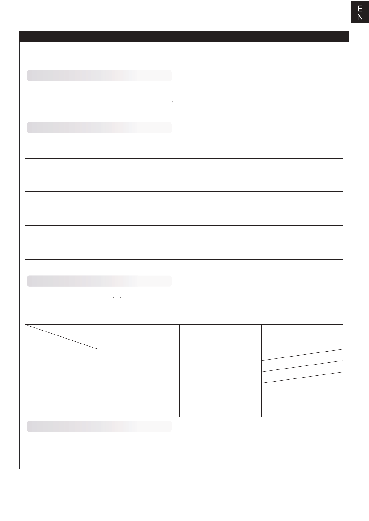
Program the ESC with your transmitter (4 Steps)
Note: Please make sure the throttle curve is set to 0 when the throttle stick is at bottom position and 100%
for the top position.
NO.1 Enter program mode
1.Switch on transmitter, move throttle stick to top position, connect the battery pack to ESC
2.Wait for 2 seconds, the motor should emit special tone like "beep-beep-"
3.Wait for another 5 seconds, special tone like "♪56712" should be emitted, which means program mode is
entered.
NO.2 Select programmable items
After entering program mode, you will hear 8 tones in a loop with the following sequence. If you move the throttle
stick to bottom within 3 seconds after one kind of tones, this item will be selected.
Prompt tone
"beep"(1 short tone)
"beep-beep-"(2 short tone)
"beep-beep-beep-"(3 short tone)
"beep-beep-beep-beep-"(4 short tone)
"beep——"(1 long tone)
"beep——beep-"(1 long 1 short)
"beep——beep-beep-"(1 long 2 short)
"beep——beep——"(2 long tone))
Note: 1 long "beep-----" = 5 short "beep-"
Selected item
brake
battery type
cutoff mode
cutoff threshold
startup mode
timing
set all to default
exit
NO.3 Set item value (Programmable value)
You will hear several tones in loop. Set the value matching to a tone by moving throttle stick to top when you hear
the tone, then a special tone "♪1515" emits, means the value is set and saved. (Keeping the throttle stick at top,
you will go back to Step 2 and you can select other items; or moving the stick to bottom within 2 seconds will exit
program mode directly) .
Items
Tones "beep-"
1 short tone
"beep-beep-"
2 short tones
"beep-beep-beep"
3 short tones
Brake
Battery type
Cutoff mode
Cutoff threshold
Start mode
Timing
Off
Lipo
Soft-Cut
Low
Normal
Low
On
NiMH
Cut-Off
Medium
Soft
Medium
High
Super soft
High
NO.4 Exit program mode
There are 2 ways to exit program mode:
1. In step 3, after special tone " ", please move throttle stick to the bottom position within 2 seconds.
2. In step 2, after tone "beep-----beep-----"(that is: The item #8),move throttle stick to bottom within 3 seconds.
15
Page 16
D
E
Warnhinweise
WARNUNG: Lesen Sie die GESAMTE Bedienungsanleitung, um sich vor der Inbetriebnahme mit den Funktionen des Produkts
vertraut zu machen.
Wenn das Produkt nicht ordnungsgemäß bedient wird, kann dies zu Schäden am Produkt oder persönlichem Eigentum führen
und schwere Verletzungen verursachen.Dieses Produkt ist kein Spielzeug! Es muss mit Vorsicht und gesundem Menschenverstand betrieben werden. Andernfalls kann es zu Verletzungen oder Schäden am Produkt oder anderen Sachwerten führen.
Dieses Produkt ist nicht für den Betrieb durch Kinder ohne direkte Aufsicht von Erwachsenen vorgesehen.
Diese Anleitung enthält Hinweise zu Sicherheit und Wartung. Es ist wichtig, dass vor der Verwendung alle Anweisungen und
Warnungen in der Anleitung gelesen und befolgt werden, um Schäden oder schwere Verletzungen zu vermeiden.
Sicherheitsvorkehrungen
Als Benutzer dieses Produkts sind Sie allein dafür verantwortlich dieses Produkt so zu betreiben, dass weder Sie selbst noch
andere gefährdet oder Schäden am Produkt oder Eigentum anderer verursacht werden.
Dieses Modell wird von einem Funksignal gesteuert, das von vielen Quellen außerhalb Ihrer Kontrolle gestört werden kann.
Solche Störungen können zu einem vorübergehenden Kontrollverlust führen. Daher sollte immer einen Sicherheitsabstand zu
Personen und Gebäuden eingehalten werden.
Altersempfehlung: Nicht für Kinder unter 14 Jahren. Dies ist kein Spielzeug.
• Betreiben Sie Ihr Modell niemals mit leeren Senderbatterien.
• Betreiben Sie Ihr Modell immer in einem offenen Bereich, abseits von Gebäuden, Verkehr oder Personen.
• Befolgen Sie die gesetzlichen Regelungen Ihres Landes zum Betrieb von ferngesteuerten Modellflugzeugen.
• Befolgen Sie sorgfältig die Anweisungen und Warnungen für dieses und alle unterstützenden Geräte, die Sie verwenden
(Ladegeräte, wiederaufladbare Akkus usw.).
• Bewahren Sie alle Chemikalien, Kleinteile und elektrischen Geräte außerhalb der Reichweite von Kindern auf.
• Feuchtigkeit verursacht Schäden an der Elektronik. Vermeiden Sie, dass die Produkte Wasser ausgesetztwerden, die nicht
speziell für diesen Zweck entworfen und geschützt sind.
• Nehmen Sie Teile des Produkts niemals in den Mund, da dies zu schweren Verletzungen oder sogar zum Tod führen kann.
Hinweise zu LiPo-Akkus
VORSICHT: Befolgen Sie immer die Anweisungen des Herstellers zur sicheren Verwendung und Entsorgung
von Batterien. Durch falsche Handhabung von Li-Po-Batterien können Feuer, Sachschäden oder schwere
Verletzungen verursacht werden.
Seien Sie sich über alle Risiken klar, die mit dem Umgang von Lithium Polymer (LiPo) Akkus verbunden sind.
Wenn die Akkus zu irgendeinem Zeitpunkt anschwellen oder aufblähen, verwenden Sie diese auf keinen Fall
mehr!
Um die Lebensdauer des Akkus zu verlängern sollten dieser bei Zimmertemperatur in einem trockenen Bereich
gelagert werden. Bewahren Sie den Akku oder das Modell nicht in einem Auto oder in direktem Sonnenlicht
auf. Wenn der Akku über einen längeren Zeitraum zu hohen Temperaturen ausgesetzt wird kann dieser
beschädigt werden oder sogar Feuer fangen.
Verwenden Sie niemals ein NiMh-Ladegerät, um Li-Po-Akkus aufzuladen. Wenn der Akku nicht mit einem
Li-Po-kompatiblen Ladegerät geladen wird, kann dies zu einem Brand führen, der zu Personen- und Sachschäden
führen kann.
Niemals Li-Po Zellen unter 3V entladen.
Lassen Sie Akkus beim Laden niemals unbeaufsichtigt.
Laden Sie niemals beschädigte Akkus auf.
Aufladen des LiPo-Akkus: Verwenden Sie ein Ladegerät, das die Li-Po-Batterie sicher aufladen kann. Lesen
Sie vor dem Gebrauch die Anweisungen des Ladegeräts sorgfältig durch. Achten Sie beim Laden des Akkus
darauf, dass sich der Akku auf einer hitzebeständigen Oberfläche befindet. Es wird auch dringend empfohlen,
den Li-Po Akku in einem feuerbeständigen LiPo-Koffer zu laden. LiPo Koffer finden Sie bei Ihrem Fachhändler
oder im Internet.
16
Page 17
Einleitung
Hintergrund
Nach dem Ende des Zweiten Weltkriegs brachten die Vereinigten Staaten und die Sowjetunion Luftfahrtexperten, Daten und
Ausrüstung aus Deutschland zurück, um ihre eigenen Düsenjäger zu entwickeln. Der F-86-Kampfjet mit dem Spitznamen
"Sabre" war ein von den USA entwickelter Düsenjäger. Es war
das Düsenjagdflugzeug der ersten Generation, der bei der U.S.
Air Force im Einsatz war für Luft-Luft-Kämpfe, Abfang- und
Bombeneinsätze. Es war auch das erste Kampfflugzeug der
Welt, das mit Luft-Luft-Raketen ausgerüstet war und das erste
US-amerikanische Kampfflugzeug mit Schleudersitz.
FMS-Modell
Aufbauend auf ihrer umfangreichen Erfahrung in der Entwicklung von ferngesteuerten Modellflugzeugen hat FMS erhebliche
Anstrengungen unternommen, um die legendäre und klassische
F-86 "Sabre" mit dem Produktstandard "Perfektes Aussehen,
hervorragende Leistung" zu versehen. Das Modell hat zahlreiche Details, wie z.B. funktionsfähige Fahrwerksklappen,
einziehbare CNC-gefrästes Fahrwerk, bewegliche Bremsklappen, Navigationslichter (links rot, rechts grün), Navigationslichter (eines rot, eines weiß) und Landescheinwerfer (weiß).
Acht 13g Digitalservos mit Metallgetriebe steuern präzise die
Querruder, Landeklappen, Seiten- und Höhenruder, um die
Manövrierfähigkeit eines Kampfflugzeugs zu simulieren. Drei 9g
Servos steuern die Bremsklappen, die den Luftwiderstand
erhöhen und die Geschwindigkeit des Flugzeugs verringern und
die Betätigung der vorderen Fahrwerksklappe, die in Verbindung mit dem Sequenzer das verzögerte Öffnen und Schließen
simuliert.
D
E
ner-Motor und einen 100A brushless Regler (mit einem 5A
Switch-Mode BEC), der für 6S 4000-5500mAh LiPo-Akku
ausgelegt ist ( Lipo Akku ist nicht im Lieferumfang
enthalten). Dieser Antrieb bietet eine hervorragende
Leistung, längere Flugzeiten und ein realistischeres,
turbinenähnliches Geräusch.
Außerdem sind wichtige Bereiche des "Sabre"-Modells, wie
Rumpf, Tragflächen und Leitwerk, mit mehreren eingebetteten Verstärkungsrohren und Verstärkungsplatten
verstärkt, die die strukturelle Festigkeit bei extremen
Flugmanövern gewährleisten.
Die zweiteilige Bauweise des Rumpfes reduziert die
Verpackungsgröße um dreißig Prozent und erleichtert den
Transport und die Lagerung. Das Modell ist in zwei
klassischen Designs erhältlich, "THE HUFF" und "SKYBLAZERS", die sowohl bei klarem oder bedecktem Himmel
leicht zu erkennen sind.
Merkmale:
1. elektronische Konfiguration: 80mm 12-Blatt Impeller
3665-KV2000 Brushless-Motor, leistungsstarker 100A ESC, 8x
13g Digitalservos mit Metallgetriebe, 3x 9g Servos.
2. realistischen Details, wie z.B. funktionsfähige Fahrwerksklappen, einziehbares CNC-gefrästes Fahrwerk, bewegliche
Bremsklappen, Navigationslichter, Landescheinwerfer, Kraftstofftanks, maßstabsgetreuer Cockpit-Innenraum, usw.
3. CNC-gefrästes, stoßgedämpftes Ganzmetallfahrwerk das
harte Landungen wirksam abfängt.
4. zweiteiliger Rumpf, die die Verpackungsgröße um dreißig
Prozent reduziert.
5. realistische Lackierung auf Wasserbasis, die ein hochwertiges Erscheinungsbild bietet.
Die PNP Version umfasst einen 12-blättrigen 80-mm Impeller
mit einen leistungsstarken bürstenlosen 3665-KV2000-Inrun-
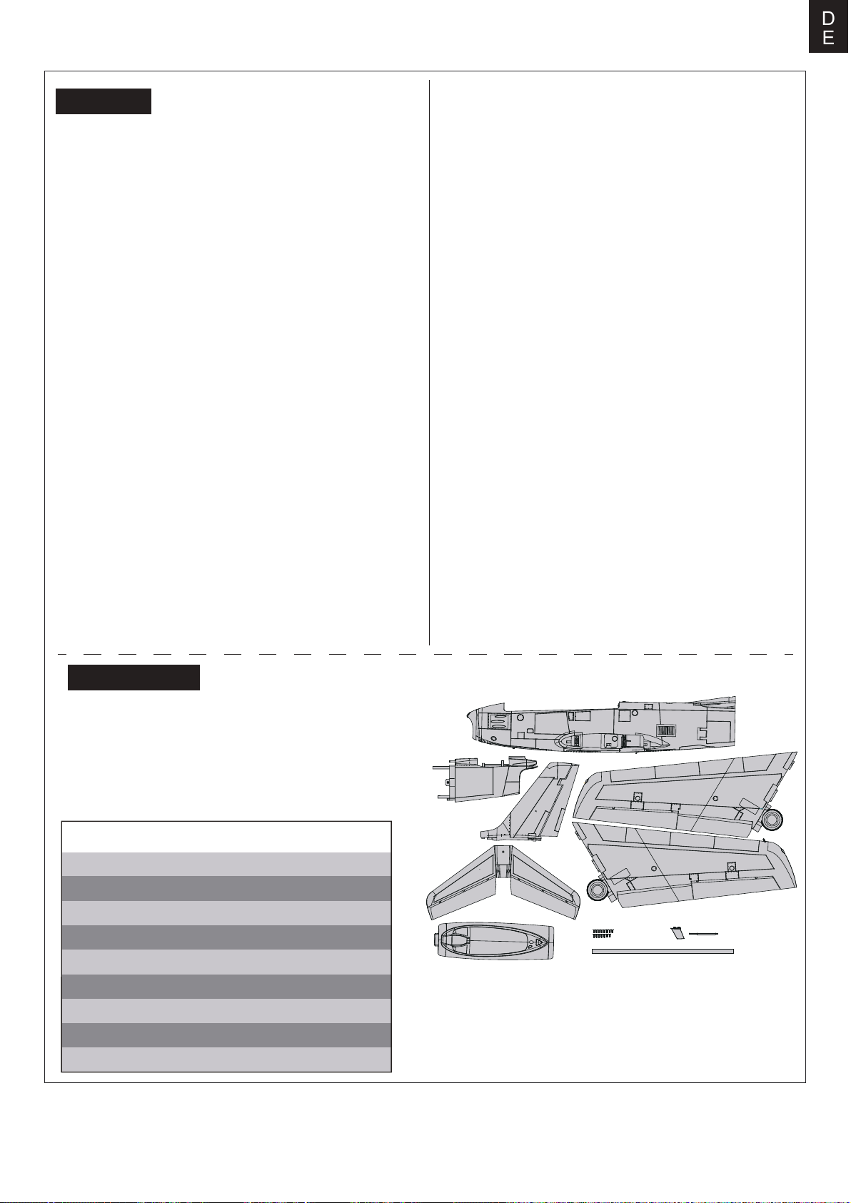
Lieferumfang
Bitte überprüfen Sie vor der Endmontage ob alle Teile des
Modells enthalten sind. Das folgende Bild zeigt den Inhalt
des Kits.
Sollten Teile fehlen notieren Sie sich bitte den Namen und
die Teilenummer (siehe Ersatzteilliste am Ende dieser
Bauanleitung) und kontaktieren Sie Ihren lokalen Händler
oder senden Sie uns eine E-Mail an info@d-power-modellbau.com.
Technische Daten
Spannweite:1220mm /48in
Länge: 1165mm /46in
Fluggewicht: ~ 3050g
Motor: 3665-KV2000
Flächenbelastung: 95.3 g/dm² ( 0.18oz/in²)
Flächeninhalt: 32dm² ( 495.8 sq.in)
Regler: 100A
Servo: 13g*8,9g*3
Empfohlener Akku: 22.2V 4000mAh-5500mAh 45c
A.
B.
D.
E.
F.G.H.
A.Vorderer Rumpf
B.Hinterer Rumpf
C.Tragflächenhälften
D.Seitenleitwerk
E.Höhenleitwerk
F.Cockpit
C.
I.
G.Schraubensatz
( HKM3.0*10mm x 13)
H.Antenne und Fluggeschwindigkeitssensor
I.Flächenverbinder
17
Page 18
D
E
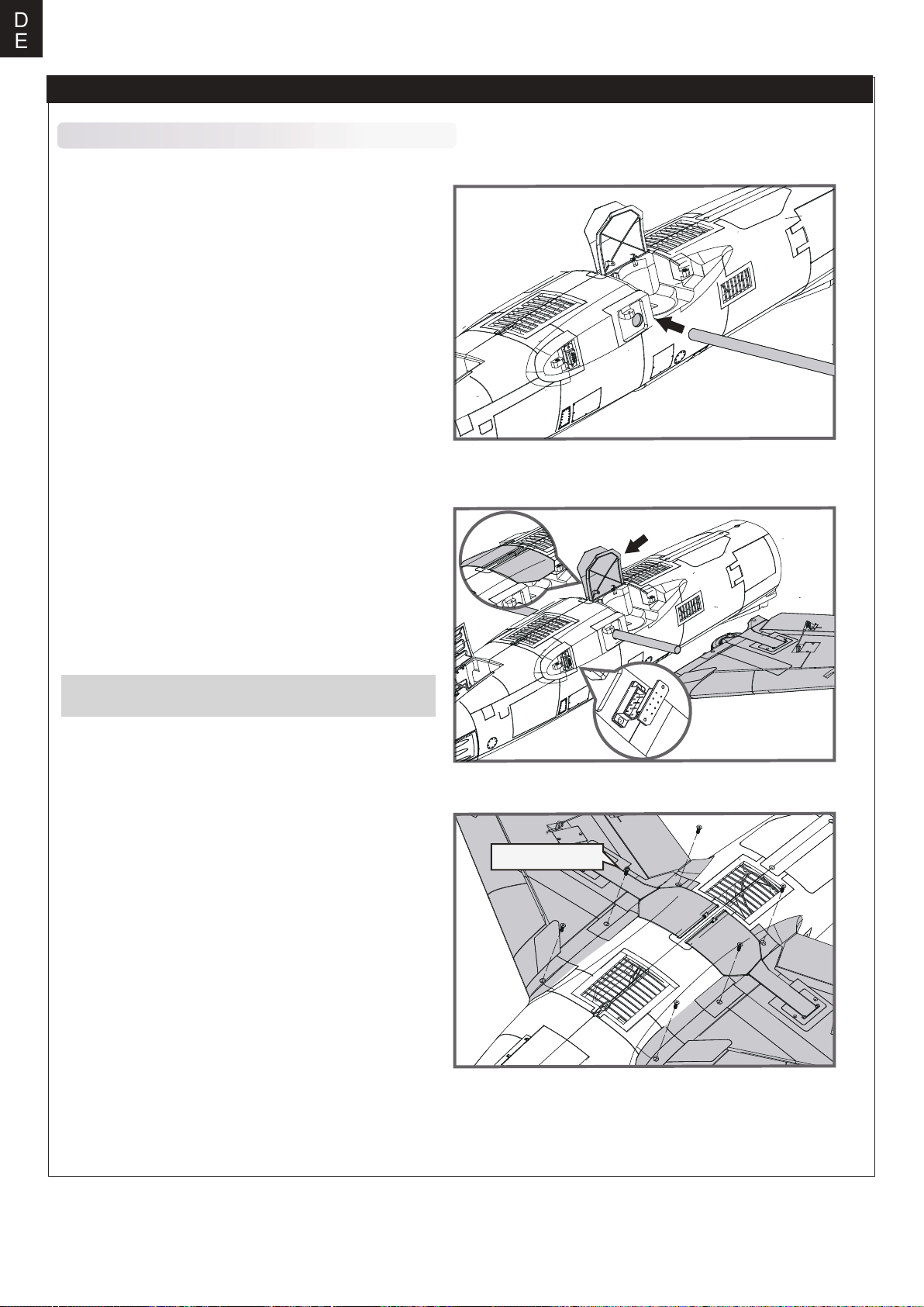
Montage des Modells
Montage der Tragflächen
1) Richten Sie den Flächenverbinder aus und schieben Sie
ihn in den Rumpf.
2.Drücken Sie die linke und rechte Türabdeckung nach unten
(d. h. in die geschlossene Position) und befestigen Sie die
linke und rechte Tragfläche mit Fahrwerk am Rumpf.
HINWEIS: Die Steckerverbindungen müssen auf beiden
Seiten fest eingesteckt sein.
3. Beide Flügelhälften mit den mitgelieferten Schrauben
(HKM3.0*10mm x 6) wie abgebildet am Rumpf befestigen.
HKM3.0*10mm
18
Page 19
Montage des Modells
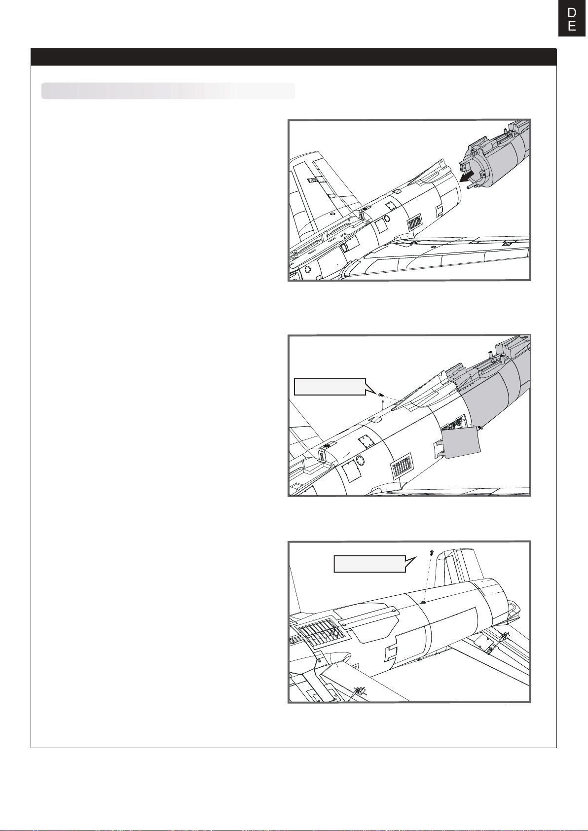
Montage des hinteren Rumpfes
1. Den hinteren Rumpf an der Rückseite des vorderen
Rumpfes ausrichten und wie abgebildet in die entsprechenden Aufnahmen stecken.
D
E
2. Die Klappe an der vorderen Rumpfseite öffnen um
die Rumpfhälften mit den Schrauben (HKM3.0*10mm)
zu befestigen.
3. Mit der Schraube (HKM3.0*10mm x 1) werden die
beiden Rumpfhälften auf der Rumpfunterseite befestigt.
HKM3.0*10mm
HKM3.0*10mm
19
Page 20
D
E
Montage des Modells
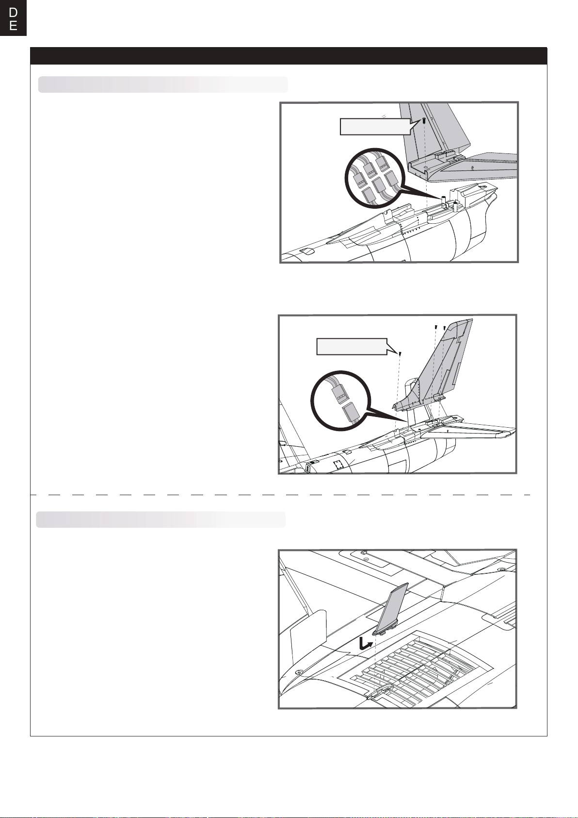
Montage der Heckleitwerke
1. Die Höhenruderservos mit den entsprechenden
Servoverlängerungskabeln im Rumpf verbinden.
Vorsichtig das Höhenleitwerk in die Aufnahme am
Rumpf stecken und mit der Schraube HKM3.0*10mm
befestigen.
HKM3.0*10mm
2. Die Seitenruderservo mit den entsprechenden
Servoverlängerungskabeln im Rumpf verbinden.
Vorsichtig das Seitenleitwerk in die Aufnahme am
Rumpf stecken und mit den 3 Schraube HKM3.0*10mm
befestigen.
Installation der vorbildgetreuen Anbauteile
1. Die nicht funktionsfähige, vorbildgetreue Antenne wie
abgebildet in den Schlitz auf der Rumpfunterseite
einstecken und in Richtung Heck schieben bis sie
einrastet.
HKM3.0*10mm
20
Page 21
Montage des Modells
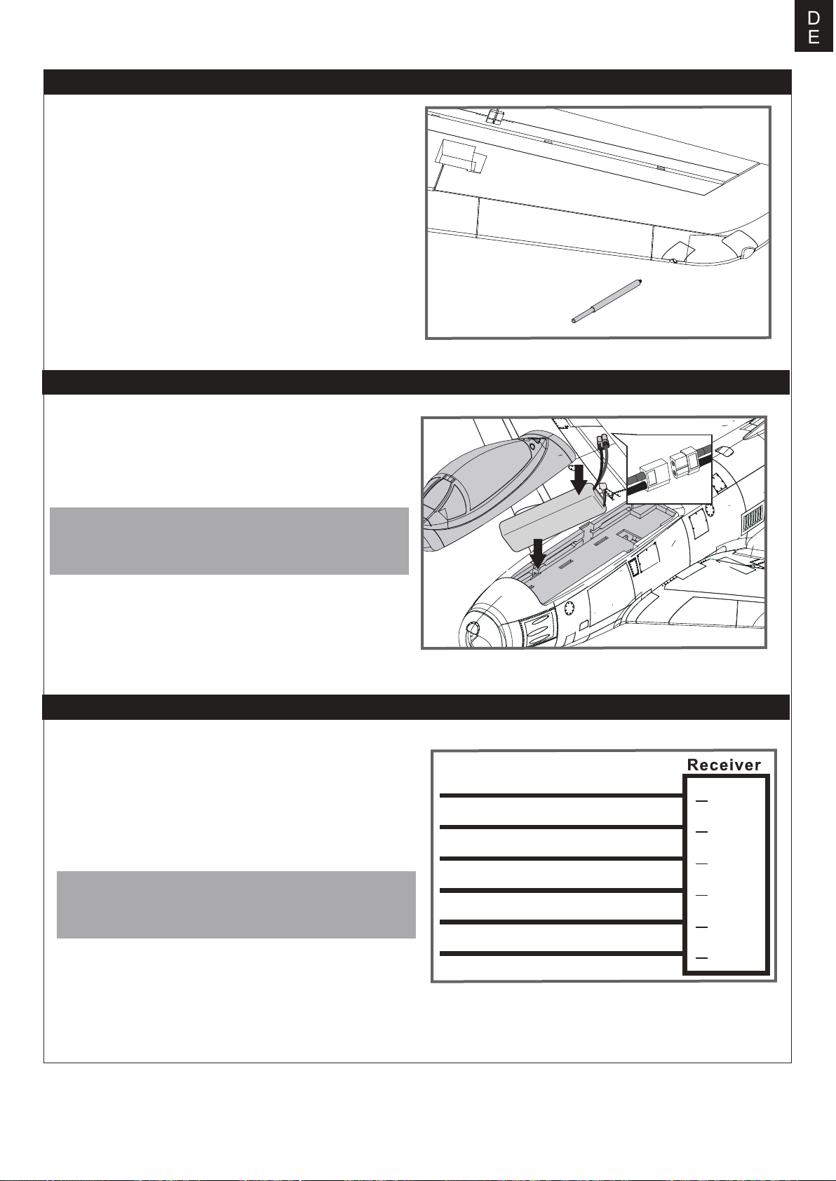
2. Den nicht funktionsfähigen, vorbildgetreuen
Fluggeschwindigkeitssensor wie abgebildet in die
entsprechende Aufnahme an der Tragflächenspitze
stecken.
Einstezen des Akkus
D
E
1. Nehmen Sie die Haube ab.
2. Befestigen Sie den Akku mit dem Klettband.
3. Schieben Sie den geladenen Akku mit den Kabeln nach
hinten in bis ganz nach vorne im Akkufach.
Hinweis: Der Schwerpunkt des Modells kann durch verschie ben des Akkus verändert werden. Der korrekte Schwerpunkt
hat Auswirkungen auf die Flugperformance.
Taille du compartiment à piles:200*68*45mm
Anschließen an den Empfänger
Die Kabel von der Servosteckerleiste sollten in der dargestellten Reihenfolge an Ihren Empfänger angeschlossen werden.
Beachten Sie, dass die LEDs von jedem freien Kanal des
Empfängers gespeist werden können. Stecken Sie die Kabel in
die Aussparung an der Rückseite der Batterieklappe.
HINWEIS: Bei Flugzeugen, die mit Wölbklappen ausgerüstet
sind, schließen Sie bitte die Wölbklappenservos an CH6 an.
Die LED-Leuchten können in jeden freien Kanal eingesteckt
werden.
Aileron
EIevator
Throttle
Rudder
Gear
Flap
1
2
3
4
5
6
Channel-1
Aile
Channel-2
Elev
Channel-3
Thro
Channel-4
Rudd
Channel-5
Gear
Channel-6
Flap
21
Page 22
D
E
Flugvorbereitungen
Wichtige Informationen zum Regler
Der eingebaute Regler ist mit einer Sicherheitsschaltung versehen. Sollte der Akku angeschlossen sein und der Gashebel
1.
nicht auf niedrig / Motor aus stehen, wird der Motor nicht starten. Wird der Gashebel ganz nach unten bewegt erzeugt der
Regler eine Tonserie. Töne in der gleichen Höhe geben die Anzahl der Zellen an die der Regler gezählt hat. Diese ist gleich
mit der Zellenanzahl des Akkus. Der Regler ist jetzt scharf geschaltet und startet den Motor wenn der Gashebel bewegt wird.
Motor und Regler sind bereits verkabelt und auch die Drehrichtung des Motors sollte korrekt sein. Sollte der Motor in die
2.
falsche Richtung drehen, tauschen Sie zwei der drei Motoranschlusskabel um die Richtung wieder zu ändern.
Der Regler ist mit einer optionalen Bremse ausgestattet. Wir empfehlen das Modell mit der deaktivierten Bremse zu fliegen.
3.
Es ist möglich die Bremse versehentlich zu aktivieren wenn der Akku mit dem Regler verbunden wird und der Gashebel auf
Vollgas steht. Um die Bremse wieder auszuschalten gehen Sie mit dem Gashebel wieder auf Vollgas und verbinden den Akku.
Vom Motor ertönt ein Piepton. Bewegen Sie den Gashebel auf Leerlauf oder Motor aus. Der Motor ist dann betriebsbereit und
die Bremse ausgeschaltet.
Akkuauswahl und Einbau:Wir empfehlen einen Lipo Akku mit
4.
verwenden muß dieser mindestens die gleichen Spezifikationen in Leistung und Abmessung aufweisen.damit der Schwer
punkt nicht wesentlich geändert wird.
Testen der Steuerfunktionen
22.2V 4000-5500mAh 45C. Sollten Sie einen anderen Akku
Bevor Sie mit diesem Schritt beginnen, binden Sie bitte der
Anleitung ihres Senders entsprechend den Empfänger mit dem
Sender.
ACHTUNG: Um mögliche Verletzungen zu vermeiden darf der
Propeller bei dem Testen der Ruder NICHT auf der Welle
montiert sein. Armieren Sie den Regler NICHT und schalten
auch nicht den Sender ein bevor es in der Anleitung des Senders vorgeben wird.
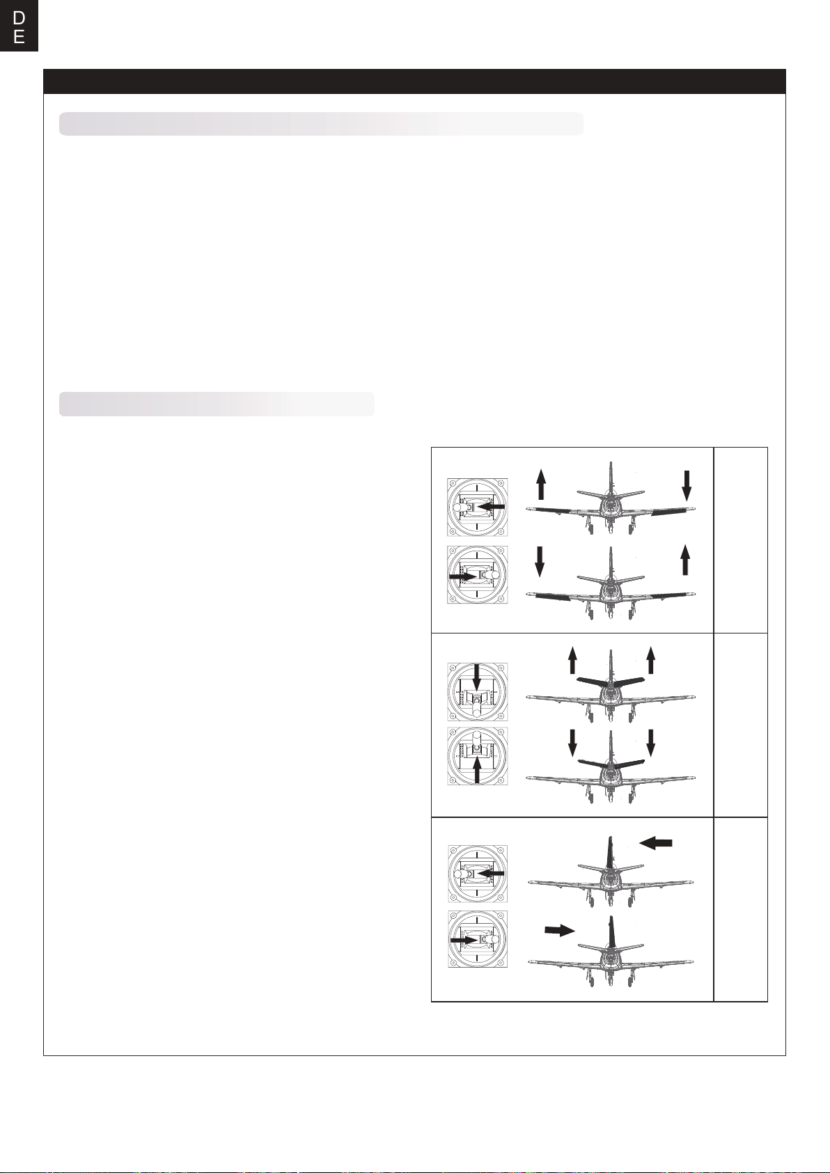
TIPP: Stellen Sie sicher, dass alle Steuerhebel auf dem Sender
auf der neutralen Position sind und der Gashebel auf Motor aus.
Stellen Sie sicher, dass beide Querruder den gleichen Weg im
Verhältnis zum Steuerknüppelausschlag ausschlagen.
Bewegen Sie die Steuerhebel des Sender um sicher zu stellen,
dass sich die Ruder korrekt bewegen. Sehen Sie dazu die
Abbildungen unten. Sollten die Ruder in die falsche Richtung
arbeiten reversieren Sie die Funktion. Lesen Sie dazu bitte in
der Anleitung des Sender nach.
Rollen links
Querruder
Rollen rechts
Steigen
Höhenruder
Sinken
Gieren links
22
Seitenruder
Gieren rechts
Page 23
Ruderausschläge
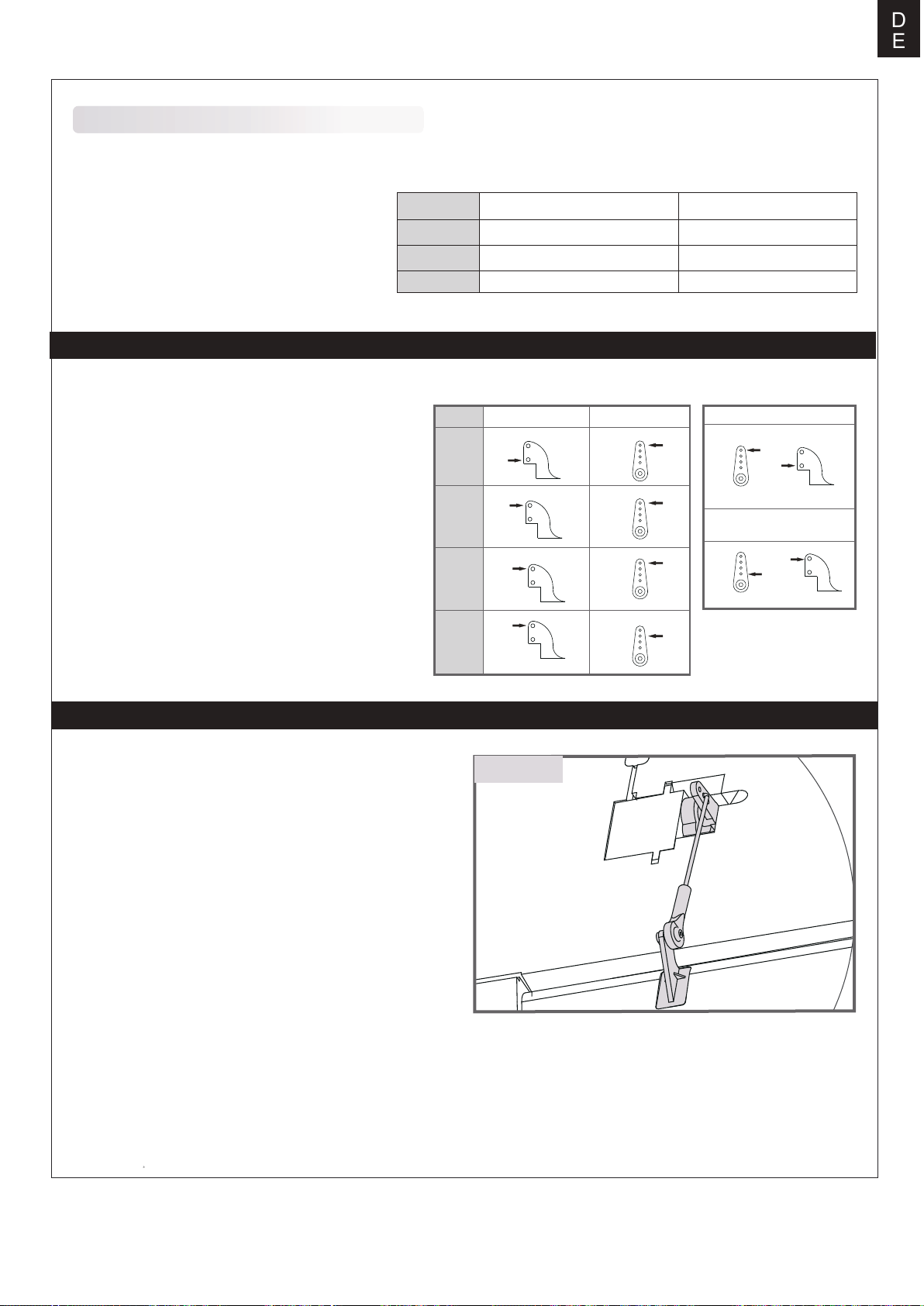
Die empfohlenen Ruderausschlag-Einstellungen sind (Dual Rate):
D
E
Tipp: Fliegen Sie das Modell beim ersten Flug mit
"normalen Ausschlägen". Wenn Sie zum ersten
Mal "maximale Ausschläge" verwenden, sollten
Sie bei niedrigen bis mittleren Geschwindigkeiten
fliegen.
Höhenruder
Querruder
Seitenruder
Ruderhorn- und Servoarm-Einstellungen
Die Tabelle zeigt die Werkseinstellungen für die Ruderhörner und Servoarme. Fliegen Sie das Flugzeug mit
den Werkseinstellungen, bevor Sie Änderungen vornehmen.Nach dem Flug können Sie die Einstellungen nach
Ihren Wünschen anpassen.
Höhen-
ruder
Seiten-
ruder
Quer-
ruder
Normale AusschlägeMaximale Ausschläge
16mm oben / unten 12mm oben / unten
14mm oben / unten
14mm links / rechts
Ruderhorn Servoarm
10mm oben / unten
10mm links / rechts
Mehr Ruderausschlag
Weniger
Ruderausschlag
Montage der Anlenkungen
Vor der Montage von Haupttragfläche, Höhen- und Seitenleitwerk werden die Gestänge für Querruder, Wölbklappen,
Höhenruder und Seitenruder eingebaut.
Stellen Sie sicher, dass die Servos in Neutralstellung sind.
Befestigen Sie das Anlenkungsstangen für Querruder, Wölbklappen, Höhenruder und Seitenruder an den entsprechenden
Löchern in den Querruder-, Wölbklappen-, Höhenruder- und
Seitenruderanlenkgestänge von außen wie abgebildet. (Bitte
beachten Sie die Abschnitte zur Einstellung der Ruderhörner
und Servoarme in der Anleitung). Installieren Sie dann das
andere Ende der Anlenkungsstangen am Kugelkopf am
Ruderhorn.
Klappen
Kugelkopf
23
Page 24
D
E
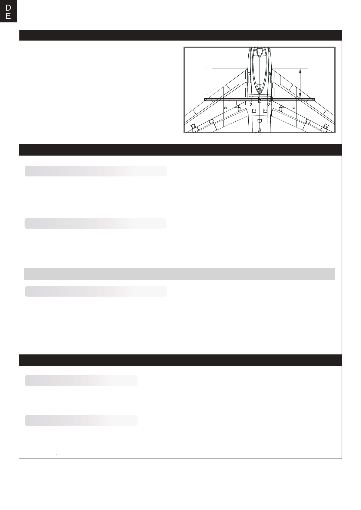
Einstellen des Schwerpunkts
Setzen Sie zum Ausbalancieren des Schwerpunktes den
Antriebsakku ein.Richten Sie den Akku so aus, dass das
Modell gerade oder mit der Nase leicht nach unten
zeigt.Nach den ersten Flügen können Sie dann den Schwerpunkt nach ihren persönliche Vorlieben einrichten.
1. Der empfohlene Schwerpunkt für das Modell befindet sich
mit eingesetztem Akku 180-190mm von der Tragflächen
vorderkante nach hinten gemessen. Markieren Sie den
Schwerpunkt auf der Tragflächenoberseite.
2. Balancieren Sie das Modell auf einer Schwerpunktwaage
aus.Bitte beachten Sie dass das Modell dabei flugfertig
ausgerüstet sein muss.
180-190mm
Vor dem Erstflug
Finden Sie einen geeigneten Flugplatz
Finden Sie einen Flugplatz frei von Gebäuden, Bäumen, Stromleitungen und anderen Hindernissen. Bis Sie wissen, wie viel
Fläche Sie zum fliegen brauchen, wählen Sie einen Platz der mindestens die Größe von 2 bis 3 Fussballfeldern hat.
Wählen Sie am besten einen RC Flugplatz eines Modellflugvereins. Fliegen Sie dabei niemals in der Nähe von Menschen besonders von Kindern, die unvorhersehbar handeln könnten.
Führen Sie einen Reichweitentest für Ihr Modell durch
Als Vorsichtsmaßnahme sollte vor jedem Flug ein Reichweitentest durchgeführt werden, um Probleme zu erkennen, die zu
einem Verlust der Kontrolle führen könnten (z.B. schwache Batterien, defekte oder beschädigte Fernsteuerungskomponenten, Funkstörungen). Dies erfordert einen Kollegen oder Assistenten.Schalten Sie zuerst den Sender ein und schließen Sie
einen vollgeladenen Akku im Modell an. Achten Sie darauf dass sich der Gasknüppel in Neutralstellung befindet. Andernfalls könnten Propeller oder Lüfter Schäden oder Verletzungen verursachen.
Hinweis: Lesen Sie zum Reichweitentest auch die Bedienungsanleitung Ihrer Fernsteuerung.
Überwachen Sie Ihre Flugzeit
Als Vorsichtsmaßnahme sollte vor jedem Flug ein Reichweitentest durchgeführt werden, um Probleme zu erkennen, die zu
einem Verlust der Kontrolle führen könnten (z.B. schwache Batterien, defekte oder beschädigte Fernsteuerungskomponenten, Funkstörungen). Dies erfordert einen Kollegen oder Assistenten.
Schalten Sie zuerst den Sender ein und schließen Sie einen vollgeladenen Akku im Modell an. Achten Sie darauf dass sich
der Gasknüppel in Neutralstellung befindet. Andernfalls könnten Propeller oder Lüfter Schäden oder Verletzungen verursachen.
Fluggrundlagen
Starten
Beschleunigen Sie das Modell vorsichtig und steuern Sie es langsam um es gerade zu halten. Erhöhen Sie die Beschleunigung und halten Sie eine gleichmäßige Geschwindigkeit um das Modell in einem schönen Anstellwinkel in die Luft steigen
zu lassen.
Fliegen
Wählen Sie immer einen weiten und offenen Platz um das Modell zu fliegen. Besuchen Sie einen RC Flugplatz eines Modellflugvereins. Fliegen Sie auf keinen Fall an Orten, an denen der Betrieb eines ferngesteuerten Flugzeugs nicht zulässig ist
(Flughäfen, Naturschutzgebiete, Siedlungen, ...).Nach dem Start bringen Sie Ihr Modell auf eine sichere Flughöhe, bevor Sie
Flugmanöver wie Rollen,Loopings oder ähnliches ausprobieren.
24
Page 25
D
E
Landen
Landen Sie das Modell, sobald Sie eine Leistungsreduz
ierung bemerken oder Ihr eingestellter Timer ertönt.Stellen
Sie Ihren Timer so ein, dass Ihnen genug Flugzeit bleibt, um
mehrere Landeanflüge zu haben.Ist das Modell mit einem
Fahrwerk ausgestattet können Sie auf harten Pisten landen.
RichtenSie das Modell direkt gegen den Wind aus und
setzen Sie mit 1/4 bis 1/3 Gas zur Landung an. Bevor das
Modell aufsetzt sollte der Gasknüppel in der 0-Stellung
stehen um Schäden am Propeller oder anderen Komponent
en zu vermeiden.
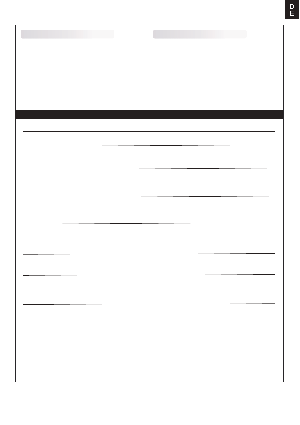
Problemlösungen
Problem Mögliche Ursache Lösung
Modell nimmt kein Gas an,
andere Steuerungsbefehle
funktionieren aber
Ungewöhnliche
Propellergeräusche oder
Vibrationen
-Regler reagiert nicht
-Gaskanal ist umgekehrt
-Spinner, Propeller,Motor oder
Motorhalterung defekt
-Spinner oder Propeller lose
-Propeller falsch herum montiert
Instandhaltung
Reparaturen am Schaummodell sollten mit schaumsicheren
Klebstoffen wie Heißkleber, Sekundenkleber speziell für
Schaumstoff oder 5.min Epoxy erfolgen.Wenn Teile nicht
reparierbar sind finden Sie am Ende dieser Anleitung die
Ersatzteilliste mit allen Bestellnummern. Überprüfen Sie vor
und nach jedem Flug ob alle Schrauben am Modell festgezo
gen sind. Achten Sie insbesondere darauf, dass Spinner und
Luftschraube vor jedem Flug fest sitzen und frei drehen.
-Gasknüppel ist nicht ganz unten oder Trimmung zu hoch
-Gaskanal am Sender umkehren
-Defekte Teile austauschen
-Lose Teile befestigen
-Propeller richtig montieren
Zu kurze Flugdauer oder
Antrieb ist nicht kraftvoll
genug
Ruder bewegen sich nicht
oder reagieren nur
langsam auf Steuerbefehle
Ruder schlagen in die
falsche Richtung aus
- Motor verliert Leistung
LED am Empfänger blinkt
langsam
- Flugakku ist zu leer
- Propeller falsch herum montiert
- Flugakku defekt
- Ruder, Ruderhörner, Anlenkung
oder Servo beschädigt
- Kabel beschädigt oder
Servosstecker lose
Kanäle auf dem Sender sind
umgekehrt
- Motor oder Akku defekt
- Stromzufuhr unterbrochen
Empfänger hat keinen Strom
- Vollständiges Aufladen des Flugakkus
- Flugakku ersetzen
- Austauschen oder Reparieren der defekten Teile
- Kabel und Stecker überprüfen
Testen der Servowegeinstellungen und Konfiguration
der Kanäle am Sender
- Akku, Empfänger, Regler, Motor und Verkabelung
überprüfen (austauschen bei Defekt)
- Modell unverzüglich landen und überprüfen
- Überprüfen der Verbindung zwischen Regler und
Empfänger.
- Servos auf Defekt überprüfen.
- Überbrüfen ob der Empfänger korrekt mit dem Sender
gebunden ist
25
Page 26
D
E
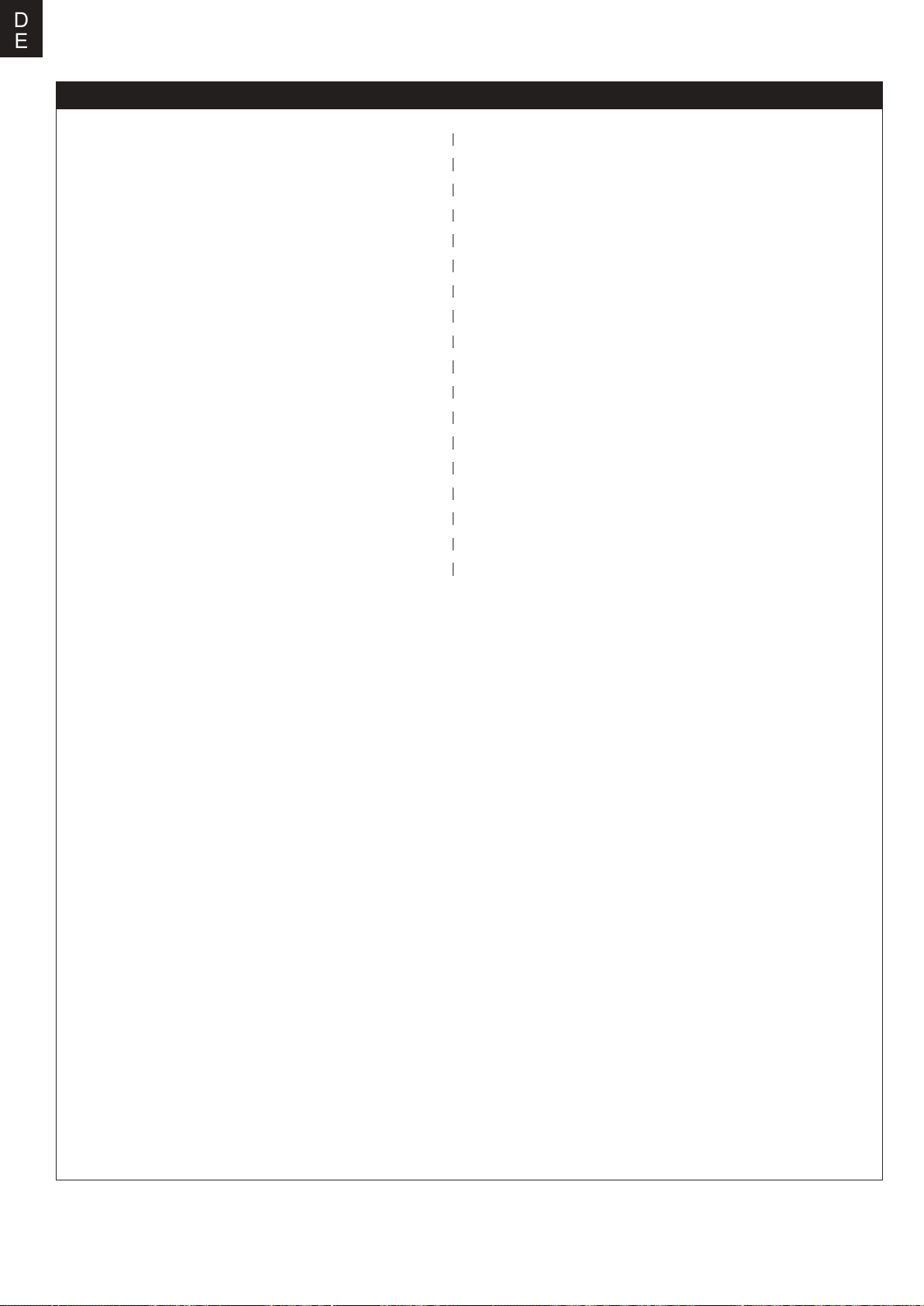
Ersatzteilliste
FMSEO101
FMSEO102
FMSEO103
FMSEO104
FMSEO105
FMSEO106
FMSEO107
FMSEO108
FMSEO109
FMSEO110
FMSEO111
FMSEO112
FMSEO113
FMSEO114
FMSEO115
FMSEO116
FMSEO117
FMSEO118
FMSEO119
FMSEO120
FMSEO121
FMSEO122
FMSEO123
FMSSDX006
Rumpf (für Huff)
Tragflächenhälften (für Huff)
Höhenleitwerk (für Huff)
Seitenleitwerk (für Huff)
Motorhaube
Kabinenhaube
Tragflächenbolzen Plastiksatz
Flächenverbinder
Steuerhorn
Vorderes Fahrwerk
Hauptfahrwerk
Vorderes Fahrwerkssystem
Hauptfahrwerkssystem
Luftgitter am Rumpf
Anlenkungsstangen
Aufkleber (für Huff)
Schraubensatz
Vordere Fahrwerksabdeckung
Hauptfahrwerksabdeckung
Abbremsklappe
Lampenabdeckung
LED-Satz
Fluggeschwindigkeitssensor (für Huff)
80mm Impeller
PRKVX2000-1
PRESC014
FMSCON012
FMSREX069
FMSREX070
PRSER003
PRSER004
PRSER005
FMSSER015
FMSSER016
FMSEO101SB
FMSEO102SB
FMSEO103SB
FMSEO104SB
FMSEO116SB
FMSEO123SB
Motor 3665-KV2000
100A ESC
Multi-Steckerset
E-Fahrwerksmechanik
E-Fahrwerksmechanik
Predator 13g digitales Metallgetriebe-Servo
positiv mit 300mm Kabel
Predator 13g digitales Metallgetriebeservo
positiv mit 460mm Kabel
Predator 13g digitales Metallgetriebeservo
negativ mit 460mm Kabel
9g digitales Metallgetriebeservo positiv mit
460mm Kabel
9g digitales Metallgetriebeservo rückwärts mit
460-mm Kabel
Rumpf(für Sky Blazer)
Tragflächenhälften(für Sky Blazer)
Höhenleitwerk(für Sky Blazer)
Seitenleitwerk(für Sky Blazer)
Aufkleber(für Sky Blazer)
Fluggeschwindigkeitssensor(für Sky Blazer)
Visitez notre site internet pour voir les photos de ces produits : www.fmsmodel.com
Saisissez le mot "ESC" dans la case de recherche pour obtenir le manuel d'utilisation du contrôleur.
26
Page 27
Anleitung des Brushless Reglers
Vielen Dank für den Kauf unseres Brushless Reglers (ESC). Hochleistungssysteme für RC-Modelle sind sehr
gefährlich, lesen Sie bitte diese Anleitung sorgfältig durch. Insofern haben wir keine Kontrolle über die korrekte
Verwendung, Installation, Anwendung oder Wartung unserer Produkte. Für Schäden, Verluste oder Kosten, die
durch die Verwendung des Produkts entstehen, wird keine Haftung übernommen. Das Auftreten von Betriebsstörungen, Ausfällen, Fehlfunktionen usw. wird abgelehnt. Wir übernehmen keine Haftung für Personen- und Sachschäden. Schäden oder Folgeschäden, die auf unser Produkt oder unsere Verarbeitung zurückzuführen sind,
werden soweit gesetzlich zulässig von uns übernommen. Der Schadensersatz ist auf den Rechnungsbetrag des
betroffenen Produktes begrenzt.
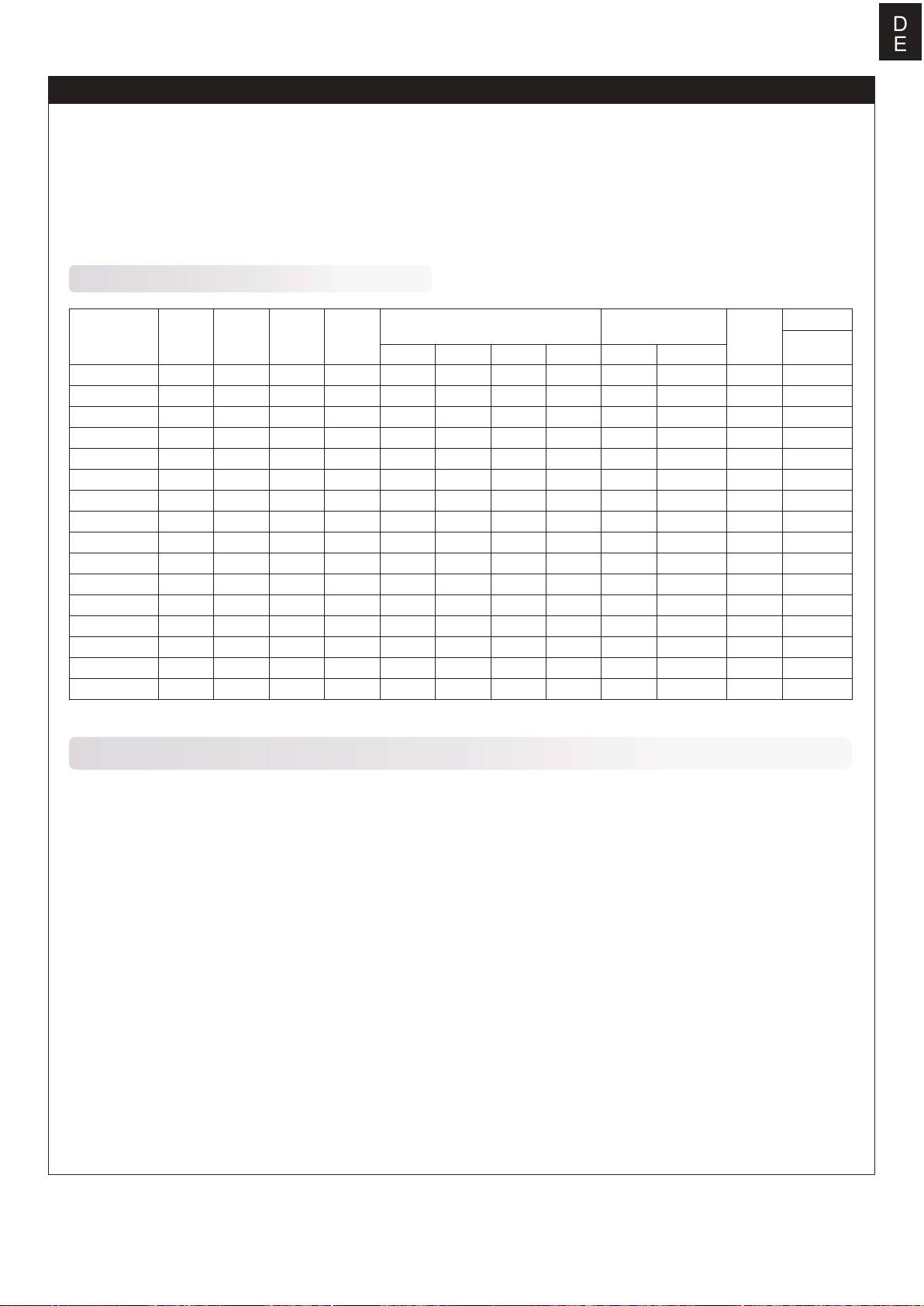
Technische Daten
D
E
Model
6A
12A
12AE
15A
20A
30A
40A
40A-UBEC
50A-UBEC
60A-UBEC
60A-UBEC
80A-UBEC
80A-UBEC
80A ESC
80Ax2+UBEC
100A ESC
Cont
Current
6A
12A
12A
15A
20A
30A
40A
40A
50A
60A
60A
80A
80A
80A
80A
100A
Burst
Current
(≤10)
8A
15A
15A
20A
25A
40A
55A
55A
65A
80A
80A
100A
100A
100A
100A
100A
BEC
Mode
Linear
Linear
Linear
Linear
Linear
Linear
Linear
Switch
Switch
Switch
N/A
Switch
N/A
Switch
Switch
Switch
BEC
Output
5V/0.8A
5V/1A
5V/2A
5V/2A
5V/2A
5V/2A
5V/3A
5V/3A
5V/5A
5V/5A
N/A
5V/5A
N/A
5V/7A
5V/10A
5V/7A
BEC Output Capability Battery Cell
2S Lipo 3S Lipo 4S Lipo 6S Lipo Lipo NiMH
3servos
3servos
5servos
5servos
5servos
5servos
5servos
5servos
8servos
8servos
8servos
2servos
4servos
4servos
4servos
4servos
4servos
5servos
8servos
8servos
8servos
5servos
6servos
6servos
6servos
6servos
6servos
6servos
2S
2-3S
2-3S
2-3S
2-3S
2-3S
2-3S
2-4S
2-4S
2-6S
2-6S
2-6S
2-6S
3-6S
3-6S
3-6S
5-6 cells
5-9 cells
5-9 cells
5-9 cells
5-9 cells
5-9 cells
5-9 cells
5-12 cells
5-12 cells
5-18 cells
5-18 cells
5-18 cells
5-18 cells
5-18 cells
5-18 cells
5-18 cells
Weight
5.5
9g
10g
16.5g
19g
37g
39g
43g
41g
63g
60g
82g
79g
79g
175g
92g
Programmierbare Elemente (Die in Fettdruck geschriebene Option ist die Standardeinstellung)
Weight
L*W*H
(mm)
32*12*4.5
38*18*6
38*18*7
48*22.5*6
42*25*8
68*25*8
68*25*8
65*25*12
65*29*10
77*35*14
86*38*12
86*38*12
86*38*12
85*36*9
85*36*9
85*36*9
1. Bremseinstellung: Aktiviert / Deaktiviert
2. Batterietyp: Lipo / NiMH
3. Abschaltmodus: Weiche Abschaltung / Soft-Cut (Verringern Sie allmählich die Ausgangsleistung) /
Abschaltung / Cut-Off (Stoppen Sie sofort dieAusgangsleistung).
4. Abschaltspannung: Niedrig / Mittel / Hoch
1) Bei Lithiumbatterien wird die Zellenzahl automatisch berechnet. Die niedrige / mittlere / hohe
Abschaltspan-nung für jede Zelle beträgt:2,85 V / 3,15 V / 3,3 V. Beispiel: Bei einem 3S Lipo beträgt die
Abschaltspannung bei Einstellung der Abschaltschwelle "Mittel":3,15 * 3 = 9,45 V.
2) Bei NiMH-Batterien betragen niedrige / mittlere / hohe Abschaltspannungen 0% / 50% / 65% der
Startspan-nung (d. H. Der Anfangsspannung vom Akku) 0% bedeutet, dass die Niederspannungsabschaltung
deaktiviert ist. Zum Beispiel: Für einen vollen geladenen 6-Zellen-NiMH-Akku, beträgt die Spannung 1,44 * 6 =
8,64 V, wenn die Abschaltschwelle "Mittel" eingestellt ist, beträgt die Abschaltspannung: 8,64 * 50% = 4,32 V.
5. Startmodus: Normal / Weich / Super-Weich (300 ms / 1,5 s / 3 s)
a) Der Normalmodus ist für Flächenmodelle geeignet. Soft- oder Super-Soft-Modi eignen sich für Hubschrauber.
Die anfängliche Beschleunigung von dem Soft- und Super-Soft-Modus sind langsamer. Der Soft-Start dauert
1,5 Sekunden, der Super-Soft-Start 3 Sekunden ausgehend von der Gasknüppelstellung Motor AUS bis Vollgas.
Wenn die Drosselklappe vollständig geschlossen ist (Gashebel unten) und wieder geöffnet wird(Gasknüppel
nach oben bewegt) Innerhalb von 3 Sekunden nach dem ersten Start wird der Neustart vorübergehend auf
Normal Modus geändert, um die Gefahr eines Absturzes durch langsame Gasannahme auszuschließen. Diese
spezielle Einstellung ist für Kunstflug geeignet wenn eine schnelle Gasannahme erforderlich ist.
6. Motor Timing: Niedrig / Mittel / Hoch (3,75 ° / 15 ° / 26,25 °)Normalerweise eignet sich für die meisten Motoren
eineniedriges Timing. Um eine höhere Geschwindigkeit zu erzielen, kann ein hoher Timing-Wert gewählt werden.
27
Page 28
D
E
Anleitung des Brushless Reglers
Beginnen Sie mit der Verwendung Ihres neuen Brushless Reglers
WICHTIG! Da verschiedene Sender unterschiedliche Gasbereiche haben, kalibrieren Sie bitte den Gasbereich,
bevor Sie fliegen.
Gasbereichseinstellung (Der Gasbereich sollte zurückgesetzt werden, wenn ein neuer Sender verwendet
wird.)
1.Sender einschalten und den Gashebel in die obere Position (Motor Vollgas) bringen.
2.Den Akku mit dem Brushless Regler verbinden und 2 Sekunden warten.
3.Der "Beep-Beep-" Ton ertönt, sobald die Vollgas Position erkannt wurde.
4.Bewegen Sie den Gasknüppel in die untere Position (Motor aus), "Beep-" Töne ertönen entsprechend der Anzahl
der Akkuzellen (Einzelzellen).
5.Ein langer "Beep-" Ton ertönt, sobald die Motor-Aus Position erkannt wurde.
Normaler Startvorgang
1.Sender einschalten und den Gashebel in die untere Position (Motor aus) stellen.
2.Den Akku mit dem Brushless Regler verbinden, ein Spezialton "♪ 123" ertönt um die Betriebsbereitschaft zu
bestätigen.
3."Beep-" Töne ertönen entsprechend der Anzahl der Akkuzellen (Einzelzellen).
4.Sobald der Selbstest abgeschlossen ist, ertönt ein langer "Beep---" Ton.
5.Den Gasknüppel aufwärtsbewegen um den Motor zu starten.
Schutzfunktion
1. Start up failure protection: If the motor fails to start within 2 seconds of throttle application, the ESC will cut-off
the output power. In this case, the throttle stick MUST be moved to the bottom again to restart the motor. (Such a
situation happens in the following cases: The connection between ESC and motor is not reliable, the propeller or
the motor is blocked, the gearbox is damaged, etc.)
2.Überhitzungsschutz: Wenn die Temperatur des Reglers über 110 Grad Celsius liegt, verringert der Regler die
Ausgangsleistung.
3. Schutz vor Signalverlust: Der Regler verringert die Ausgangsleistung, wenn das Gassignal für 1 Sekunde lang
unterbrochen ist. Der Motor wird vollständig abgeschaltet wenn das Gassignal für 2 Sekunde lang unterbrochen ist.
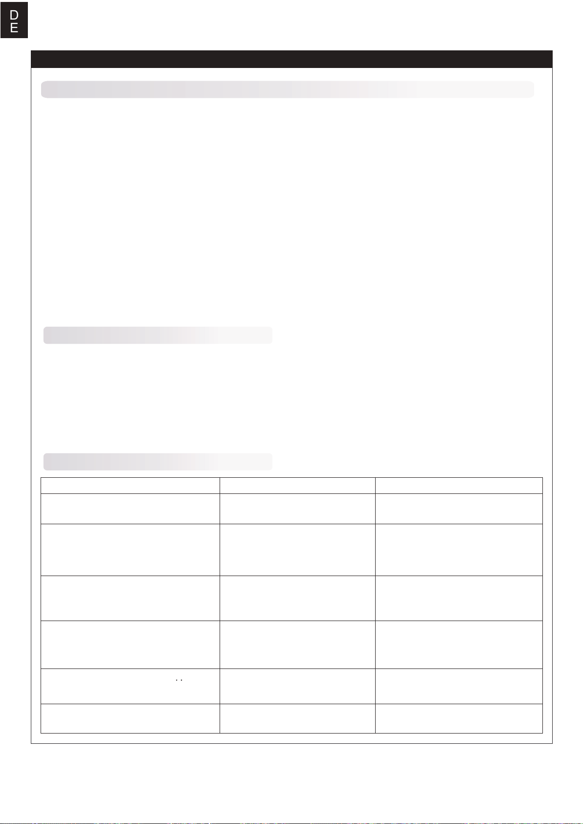
Fehlerbehebung
Fehler
Nach dem Einschalten funktioniert der
Motor nicht, kein Ton wird ausgegeben
Nach dem Einschalten funktioniert der
Motor nicht. Ein solcher Alarmton ertönt:
"Beep-Beep-, Beep-Beep-,Beep-Beep-"
(Jeder Piepton hat ein Zeitintervallvon
etwa 1 Sekunde)
Nach dem Einschalten funktioniert der
Motor nicht. Ein solcher Alarmton ertönt:
"Beep-, Beep-, Beep-" (Jeder "Beep-" hat
ein Zeitintervall von ca. 2 Sekunden)
Nach dem Einschalten funktioniert der
Motor nicht. Ein solcher Alarmton ertönt:
"Beep-, Beep-, Beep-" (Jeder "Beep-"
hat ein Zeitintervall von ungefähr 0,25
Sekunden)
Nach dem Einschalten funktioniert der
Motor nicht Spezialton "♪56712" ertönt
nach 2 Signaltönen (Beep-Beep-)
Der Motor läuft in die entgegengesetzte
Richtung.
Die Verbindung zwischen Batterie
Pack und ESC ist nicht korrekt
Eingangsspannung ist abnormal,
zu hoch oder zu niedrig
Das Gassignal ist unregelmäßig
Der Gasknüppel ist nicht in der
untere (niedrigste) Position
(Motor aus)
Richtung des Drosselkanals ist
umgekehrt, so wird der
Programm-Modus erreicht
Die Verbindung zwischen dem
Brushless Regler und dem Motor
muss gewechselt werden.
Mögliche Ursache Maßnahme
Überprüfen Sie den Stromanschluss
Ersetzen Sie den Stecker
Überprüfen Sie die Spannung des
Akkus
Überprüfen Sie den Empfänger und
den Sender. Überprüfen Sie das
Kabel des Gaskanals.
Bewegen Sie den Gashebel in die
untere Position
Stellen Sie die Richtung des Gaskanals richtig ein
Vertauschen Sie zwei der drei
Anschlusskabel zwischen dem
Brushless Regler und dem Motor
28
Page 29
Programmieren Sie den Regler mit Ihrem Sender (4 Schritte)
Hinweis: Stellen Sie sicher, dass der Gasweg auf 0 eingestellt ist, wenn der Gasknüppel sich in der unteren
Position befindet und 100% wenn der Gasknüppel sich in der oberen Position ist.
NO.1 Rufen Sie den Programmiermodus auf
1.Sender einschalten, Gashebel nach oben bewegen Position, verbinden Sie den Akku mit Brushless Regler.
2.Warten Sie 2 Sekunden, es sollte nun einen spezieller Ton wie "Beep-Beep-" ertönen.
3.Warten Sie weitere 5 Sekunden, nun ertönt ein Spezialton "♪56712" ,nun wird der Programmiermodus
aufgerufen.
NO.2 Programmierbare Einstellung auswählen
Nach dem Aufrufen des Programmiermodus hören Sie 8 Töne in einer Schleife in folgender Reihenfolge. Wenn
Sie den Gasknüppel bei der gewünschten Funktion innerhalb von 3 Sekunden nach unten bewegen, wird diese
ausgewählt.
D
E
Schneller Ton
"Beep" (1 kurzer Ton)
"Beep-Beep-"(2 kurze Töne)
"beep-beep-beep-"(3 short tone)
"Beep-Beep-Beep-Beep-"(4 kurze Töne)
"Beep -----" (1 langer Ton)
"Beep ----- Beep-"(1 langer 1 kurzer)
"Beep ----- Beep-Beep-"(1 langer 2 kurze)
"Beep ----- Beep -----"(2 lange Töne)
Hinweis: 1 langer Beep ----- = 5 kurze Beep-
alle auf Standardeinstellung (Werkseinstellung) setzen
Ausgewählter Eintrag
Bremse
Batterietyp
Abschaltmodus
Abschaltspannung
Startmodus
Timing
beenden
NO.3 Stellen Sie den Wert der ausgewählten Einstellung ein (programmierbarer Wert)
Sie hören mehrere Töne in einer Schleife. Stellen Sie den passenden Wert für einen Ton ein, indem Sie den Gashebel
in die obere Position (Motor Vollgas) bewegen wenn Sie den Ton hören. Dann ertönt ein Spezialton "♪1515". Dies
bedeutet, dass der Wert eingestellt und gespeichert ist. (Wenn Sie den Gasknüppel oben lassen, kehren Sie zu
Schritt 2 zurück und können weitere Einstellungen auswählen.
Wenn Sie den Stick innerhalb von 2 Sekunden nach unten bewegen, wird der Programmiermodus direkt beendet.
Einstellungen
Töne "Beep-"
1 kurzer Ton
"Beep-Beep-"
2 kurze Töne
"Beep-Beep-Beep"
3 kurze Töne
Bremse
Batterietyp
Abschaltmodus
Abschaltspannung
Startmodus
Timing
aus
Lipo
weiche Abschaltung (Soft-Cut)
Niedrig
Normal
Niedrig
Abschaltung (Cut-Off)
ein
NiMH
Mittel
Weich
Mittel
Hoch
Super-Weich
Hoch
NO.4 Verlassen Sie den Programmiermodus
Es gibt zwei Möglichkeiten, um den Programmiermodus zu beenden:
1. In Schritt 3, nach dem Spezialton "1515", den Gasknüppel innerhalb von 2 Sekunden auf 0 setzen (Motor aus).
2. In Schritt 2, nach dem Ton "Beep ----- Beep-----" (Einstellung Nr.8), den Gasknüppel innerhalb von 3 Sekunden
auf 0 setzen (Motor aus).
29
Page 30
C
N
警告
警告:在组装、调整及飞行前请务必认真阅读产品说明书以熟知产品的特性。请严格按照说明书提示进行飞机的
组装、调整及飞行。如操作不当会造成产品本身损坏及其它财产损失,甚至造成严重的人身伤害。
声明:模型不是玩具,具有一定的危险性,操作者需要具备一定的飞行经验,初学者请在专业人士指导下操作。
禁止十四岁以下儿童操作、飞行。
安全须知
本产品飞行由无线电遥控器控制,在飞行过程中可能会受到外
界强信号源干扰而导致失控,甚至坠机。因此,在飞行
过程中务必始终与飞机保持一定的安全距离,避免意外碰撞、
受伤。
⸺请勿在发射器电池低电量的情况下操纵模型飞机。
⸺请勿在公路、人群、高压线密集区、机场附近及其它法律法规明确禁止飞行的场合飞行。
⸺请勿在雷雨、大风、大雪或者其它恶劣气象环境下飞行。
⸺请严格遵照产品指导说明及安全警告操作本产品及其相关配置(例如充电器、电池等)。
⸺请勿将相关化工类产品、零部件、电子部件等置于儿童可触及的范围。
⸺请勿将电子件暴漏于潮湿的环境中,以免造成损坏。
⸺请勿将本品任意处置于口中,以免造成人身伤亡。
锂聚合物电池使用安全须知
使用锂聚合物电池时,须严格遵守制造商说明、要求并了解相关风险,使用不当会导致锂聚合物电池起火,从而造
成严重的财产损失甚至人身伤害。
禁止使用变形、胀气的锂聚合物电池。
禁止使用过充、放电的锂聚合物电池,避免发生危险。长时间不使用须将锂聚合物电池放电至存储电压(3.8~3.85V
/ 节)。锂聚合物电池须储存在室内干燥区域(4.5~48.5℃),禁止将锂聚合物电池置于阳光下暴晒或车内,高温可
能会导致锂聚合物电池起火,造成财产损失和人身伤害。
请使用专用充电器对锂聚合物电池进行充放电,禁止使用其它如:镍氢电池充电器。充放电时,禁止将锂电池放置
于高温物体表面,建议使用锂电池防爆袋。不正确的充放电操作会对锂聚合物电池造成损伤,甚至会引起火灾,造
成财产损失和人身伤害。
禁止将锂聚合物电池单节电压放至低于 3V,禁止给已损坏的锂聚合物电池充电。
锂聚合物电池充放电须在有人看管的情况下进行,避免发生意外造成不必要的损失。
飞机电池充电警告:
请确保使用合格的电池充电器给锂电池充电。在使用充电器前,请认真阅读充电器说明书。充电过程中,请确保把
电池置于耐热的表面。建议把锂电池置于防火充电袋内充电,防火充电袋可在相关模型实体店或网上买到。
44
Page 31
产品特点
第二次世界大战结束,美国和苏联分别从德国带回了航空设
备研制专家、资料及设备,分别打造了自己国家的喷气式战斗机。
F-86战斗机“佩刀”是美国研制的后掠翼喷气式战斗机,是美国空
军装备的第一代喷气式战斗机,可用于对空作战,空域拦截与轰
炸执行,是世界上第一架装备空对空导弹的战机,也是美国第一
架装设弹射椅的战斗机。
FMS在丰富的研发制造遥控模型战斗机经验的基础上厚积薄
发,以“精于静,精于动”的产品标准高还原度复刻了这款传奇经
典的“佩刀” F-86。兼具外观和功能像真性的细节比比皆是,如可
延时开合的舱门、可收放CNC加工起落架、可活动减速板、机翼航
灯(左红右绿)、尾喷口航灯(一红一白)和着陆灯(暖白色)等,外
观静态像真细节也不曾忽略,如油箱、座舱内饰(模制胶件成型)、
空速管、天线等。8个13g全金属数码舵机控制副翼、襟翼、方向舵
和升降舵,精准执行输入指令完成仿真战机机动动作,俯仰、横
滚、滚转、翻转轻松玩转;3个9g半金属舵机控制减速板和前起落
架舱门开合,前者可增加飞机的阻力,减小速度,后者在延时器的
作用下可模拟控制起落架舱门的延时开启和关闭,确保起落架的
展开或收起过程中,舱门的操作与起落架的运动同步,以确保安
全性和流畅性。
PNP配置包含12叶片80mm涵道,大功率3665-2000Kv无刷
内转电机和100A电调(带5A开关BEC),与市场上常见的6S
4000-5500mAh LiPo电池搭配(电池需另购),高配置动力及操
控系统给“战斗”飞行提供更出色的性能、更长的飞行时间和更仿
真的类涡轮发动机声浪。
此外,“佩刀”机身、机翼、尾翼等关键位置预埋多根加强管和
加强片,保证极限飞行姿态下的机体强度。机身采用两段式设计,
将包装尺寸缩小百分之三十,便利装载和运输。两款经典涂装,
THE HUFF和SKYBLAZERS,无论晴空万里还是浓云密布都极具
辨识度。
C
N
特征:
• 电子配置:80mm12叶涵道,3665-KV2000无刷电机,高性能
100A电调,13g全金属数码舵机X 8pcs,9g半金属舵机X
3pcs;
• 动、静态像真细节丰富,如可延时开合的舱门、可收放CNC加
工跪式起落架、可活动减速板、航灯和着陆灯、油箱、座舱内饰
(模制胶件)等;
• CNC加工全金属起落架,自带减震,无虚位,强度高,有效对抗
暴力降落;
• 两段式机身设计,将包装尺寸缩小百分之三十;
• 仿真水性漆涂装,极具质感。
产品组成
在组装产品之前,请仔细检查以下配件,如有缺失或者损坏,
请及时联系当地店面或者邮件至厂家(support@fmsmodel.
com),告知缺失或损坏的配件名称及编码(请在本说明书尾
页查看相应的配件编码)。请注意,不同配置,包装盒内部
物品不同。
产品参数
翼展:1220mm /48 in
机身长: 1165mm /46in
飞行重量: ~ 3050g
电机: 3665 KV2000
翼载荷:95.3 g/dm² ( 0.18oz/in²)
翼面积: 32dm² ( 495.8 sq.in)
电调: 100A
舵机: 13gX8,9gX3
涵道:80mm12叶
推荐电池: 22.2V 4000mAh-5500mAh 45c
A.
B.
D.
E.
F.G.H.
A:前机身
B:后机身
C:主翼
D:垂尾
E:平尾
F:座舱组
C.
I.
G:螺丝组(HKM3.0*10mm x 13)
H:天线和空速管
I :主翼对接管
45
Page 32
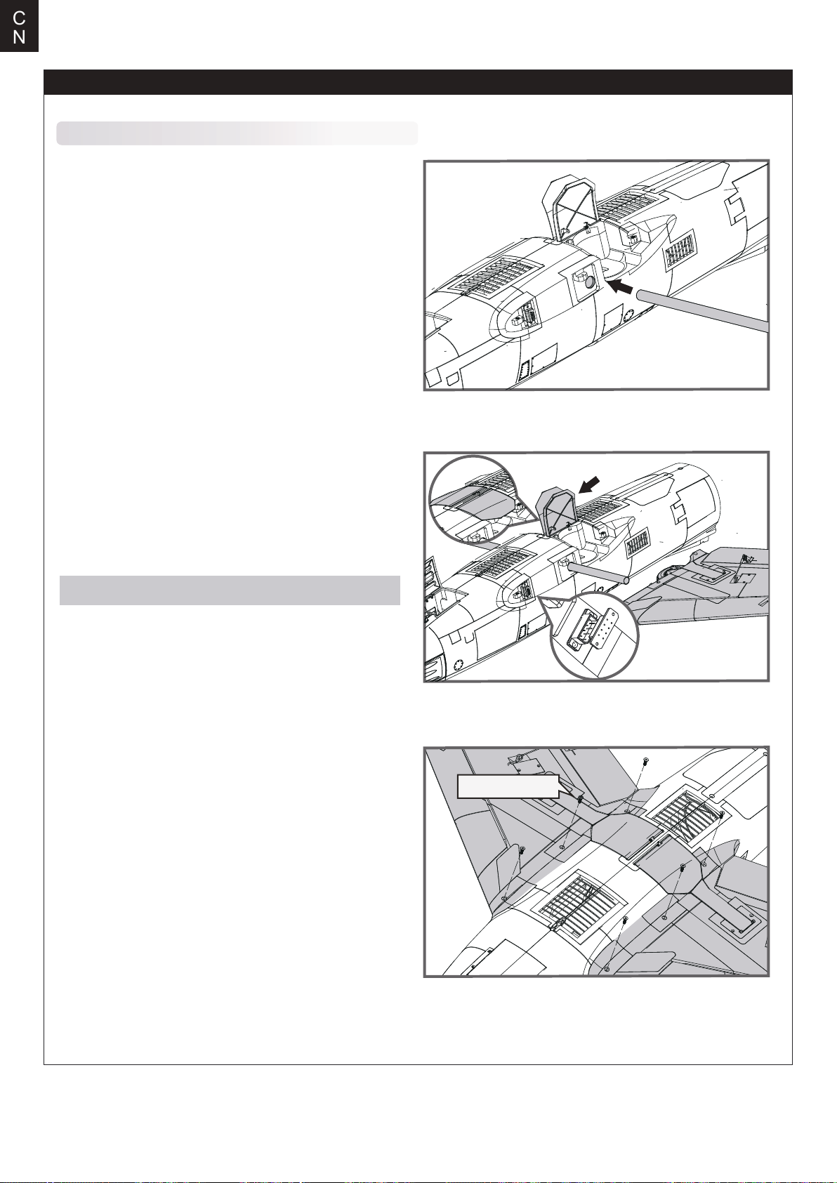
C
N
机体安装
主翼安装
1. 如图所示,将主翼对接管装入机身槽位。
2. 将左右两侧舱门盖板向下压至底部(即关闭状态),将
装有起落架的左右两侧机翼安装至机身。
注意:确保插牢机翼和机身的对接插头。
3. 所用所附螺丝(HKM3.0*10mm x 6)固定机翼至机
身。
HKM3.0*10mm
46
Page 33
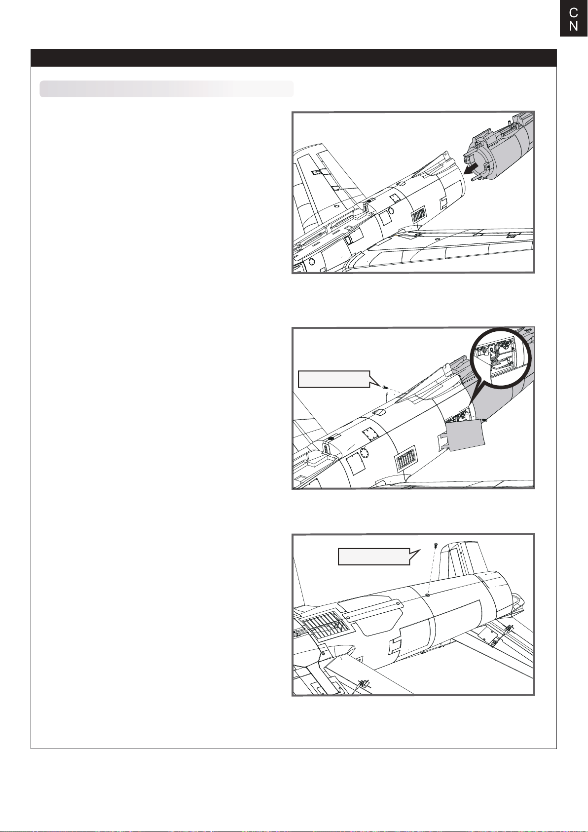
机体安装
后机身安装
1. 如图所示, 前机身延长线穿过后机身线槽,对准并安
装后机身至前机身尾部相应槽位。
C
N
2. 使用遥控器的襟翼通道打开机尾减速板,使用所附螺丝
(HKM3.0*10mmX 2)从水平方向上将后机身固定到位。
3. 保持机身底部朝上,使用所附螺(HKM3.0*10mmX 1)固
锁前后机身。
HKM3.0*10mm
HKM3.0*10mm
47
Page 34
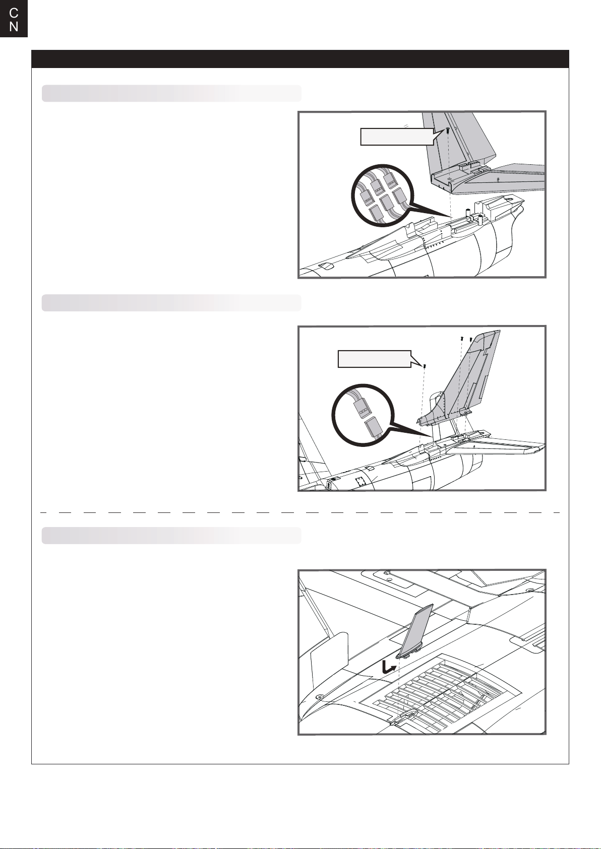
C
N
机体安装
平尾安装
HKM3.0*10mm
1. 如图所示,分别将平尾舵机线、LED灯线与机身预
埋的舵机延长线连接,将平尾安装至机身尾部槽位,
并使用所附螺丝(HKM3.0*10mm X1)固定。
垂尾安装
1. 如图所示,连接垂尾舵机线和与机身预埋的舵机延
长线,安装垂尾至机身尾部垂尾槽位,并使用所附螺
丝(HKM3.0*10mm X 3)将垂尾固定到位。
像真件安装
1. 如图所示,将像真天线安装至机身底部槽位,并向机身
尾部方向滑动固定。
HKM3.0*10mm
48
Page 35
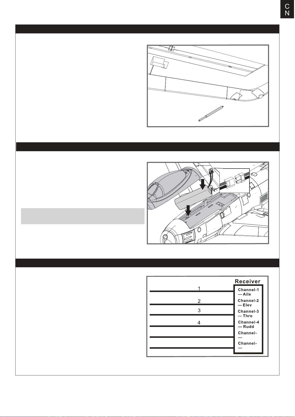
机体安装
2. 如图所示,将像真空速管插装至翼尖孔位。
电池安装
C
N
1. 移开座舱。
2. 取下电池板上的魔术贴(毛面)贴于电池表面。
3. 如图所示,将电池置于电池舱内,用魔术带绑紧,使有电源
线的那端朝向飞机的尾部。
注意:由于不同电池厂家生产的电池重量有轻微的差异,需要
调整电池的前后位置来平衡飞机的重心位置。
电池仓尺寸:200*68*45mm
接收机连接示意图
如图所示,以 Futaba 遥控器为例,将副翼舵机信号线插入接
收机副翼通道、升降舵舵机信号线插入接收机升降舵通道、
方向舵舵机信号线插入接收机方向舵通道、电调信号线插入
接收机油门通道。最后将所有连接线整理整齐并固定在电池
仓后部的凹槽内,随后固定好接收机 。
副翼
平尾
油门
垂尾
起落架
其他通道
5
6
5
Gear
6
Spare
49
Page 36
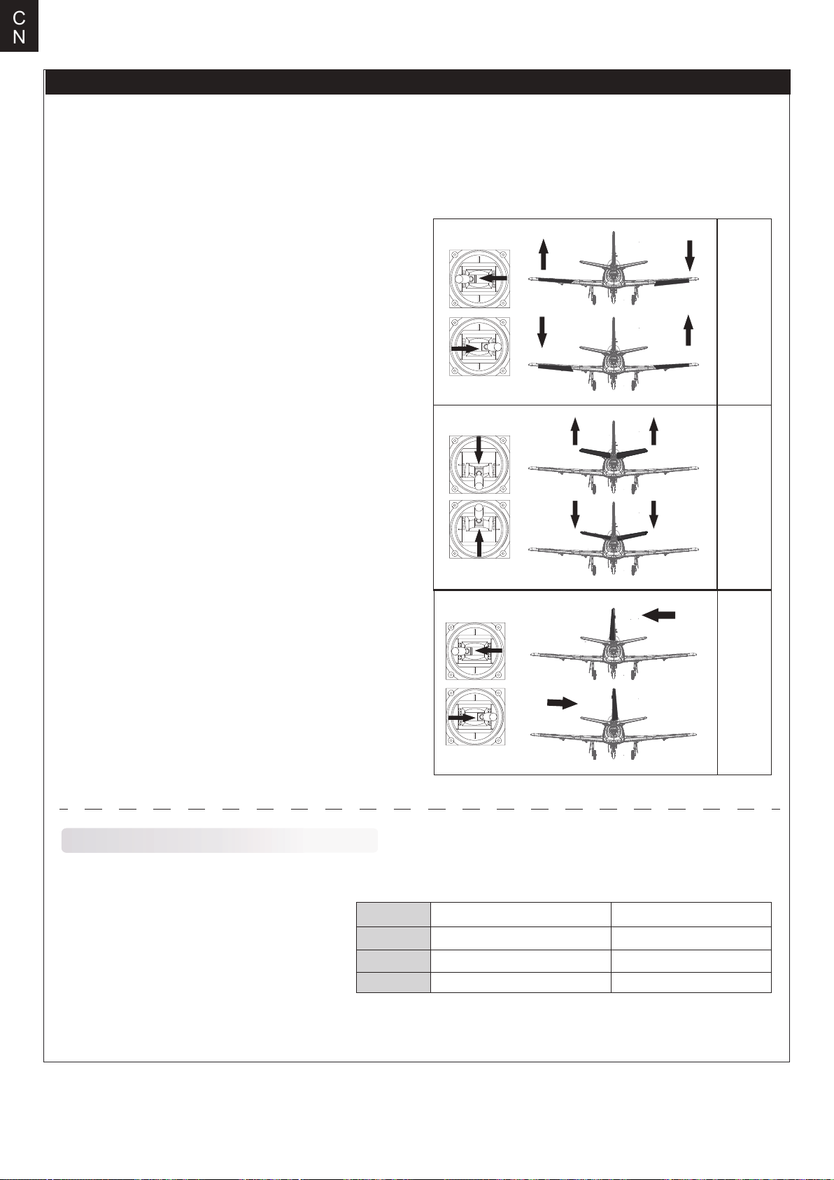
C
N
遥控器设置
警告:为保证安全,在遥控器参数设置及舵面调整过程中,请务必拆下螺旋桨,以免电机意外启动发生事故。遥控器发射机开机
前,确保油门杆在最低位置,其它摇杆在中立位置。开发射机并给接收机通电,随后听到电调初始化音(音符释义见后文“电子
调速器说明书”)。观察所有舵面是否回中,如果没有回中,尽量通过调整舵机摇臂角度、连杆长度的方式来使舵面回中,若调
整长度在安全范围内仍未回中,则使用遥控器通道微调或者菜单中的“SubTrim”选项来使舵面归中。如下图所示观察摇杆动作与
舵面动作的对应关系,如发生舵面反向需要使用遥控器中的通道反向功能来纠正。
左推
1.移动发射器上的控制杆位置,确保舵面可以自如移动。
副翼
右推
爬升
升降
降落
转左
转向
推荐舵面行程
温馨提示:首飞建议用小舵面行程
升降舵
副翼舵
方向舵
50
转右
大小
16mm 上 / 下12mm 上 / 下
14mm 上 / 下
14mm 左/右
10mm 上 / 下
10mm 左/右
Page 37
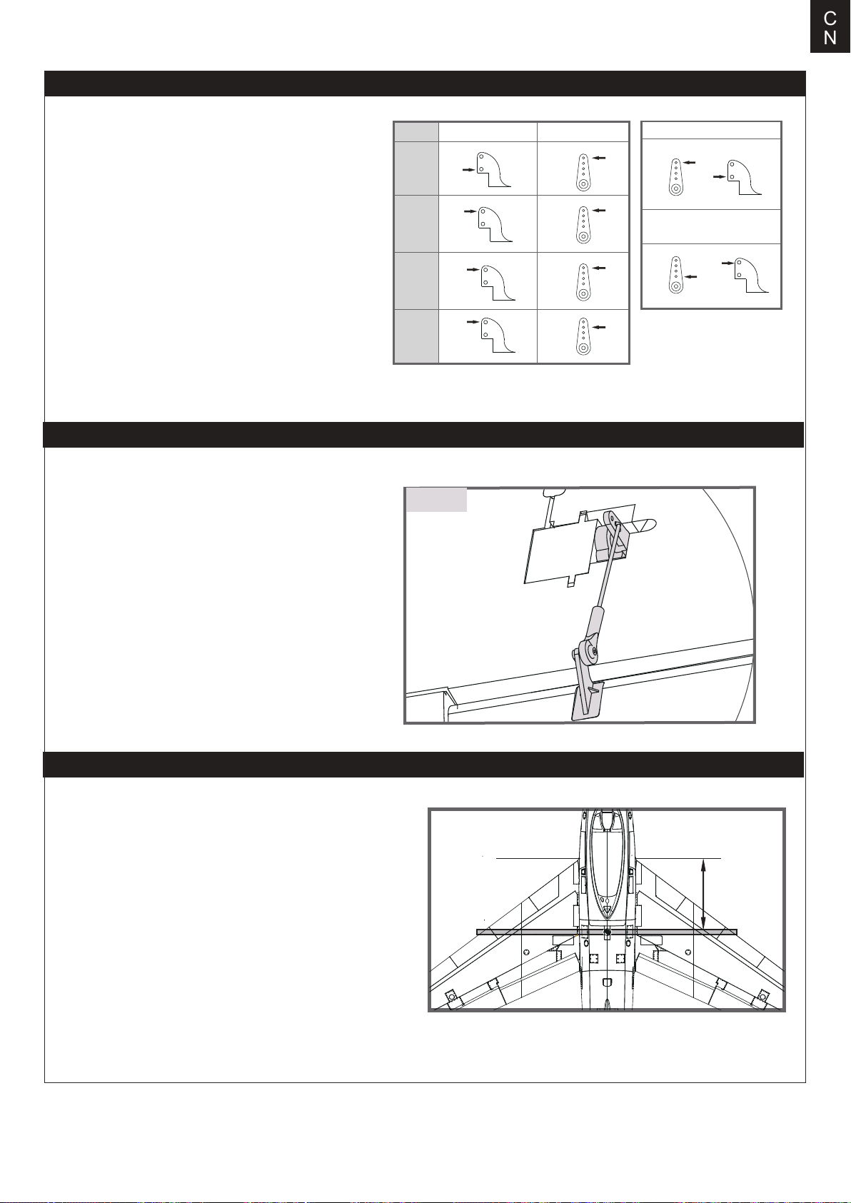
舵角和舵机摇臂安装
C
N
图示是舵角和舵面摇臂的出厂设置。首飞建议用出厂设置
的舵角飞行。首飞后,可按图调整舵角。
连接钢丝安装
在安装主翼、平尾、垂尾之前需先安装副翼、襟翼、升降
舵、方向舵的连接杆。具体步骤如下:保持舵机在回中状
态,将副翼、襟翼、升降舵、方向舵舵面的连接钢丝有
“Z”型折弯的一头由外侧装入相应的舵机摇臂孔位(请参
考“舵角和舵机摇臂安装”相关步骤)再将钢丝另一端的
球头扣安装到各舵角相应的球头上。
平尾
垂尾
副翼
襟翼
球头
舵角 摇臂
大舵面
小舵面
重心调整
通过移动电池在电池舱内的前后位置调整飞机的重心 ,使飞机保
持水平或稍微头重的状态。首飞以后,重心位置可以根据你自
己的飞行偏好再做更改。
1.如图所示,推荐重心位置是机翼前缘往后 180-190mm处(安
装电池以后)。推荐把食指放在机翼下面的重心位置来帮助调
整重心。
2.在调整飞机重心的时候请确定飞机处于组装完毕待飞的状态。
180-190mm
51
Page 38
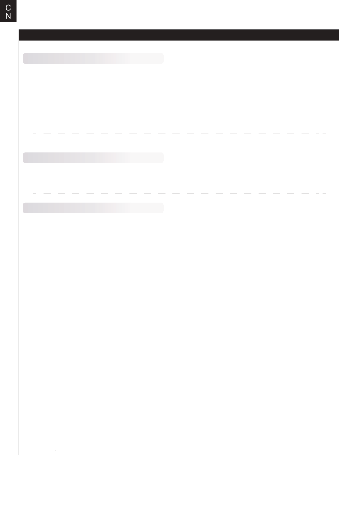
C
N
飞行前准备
起飞前的检查
每次飞行前须做严格的地面检查,可有效避免飞行事故的发生。
1. 检查全机螺丝是否安装到位、舵角摇臂连接可靠。机翼快拆装置已锁紧。
2. 安装电池,并调整飞机重心到说明书推荐位置。
3. 动力电池、遥控器发射机电池等已充满电,处于可靠工作状态。
4. 发射机油门杆保持在最低位(推荐使用带有油门锁定功能的遥控设备),打开发射机,随后连接动力电池,待电调初始化完成
后检查各个舵面是否回中,是否动作正确。
5. 轻推油门观察螺旋桨转向是否正确。
所有检查完成后,方可进行飞行,初学者首次飞行需要有经验的爱好者协助完成,避免因操作不当发生飞行事故。
合适的飞行场地
航模飞行须远离人群、建筑物、树木、高压线及禁飞区的空旷场地(至少 2-3 个足球场大小)。初学者飞行前需要向有经验的爱
好者询问相关安全事宜。
关于飞行时间
厂家推荐的飞行时间是使用厂家推荐型号的电池,由有经验的爱好者在微风天完成飞行测试得到的飞行时间,该时间与电池参数、飞
机全备重量、飞行条件以及飞行手法相关,不同飞行条件可能得到不同的飞行时间。
建议爱好者在飞行时使用遥控器的“计时功能”,建议初始飞行时间设定为 4 分钟,飞行时间倒计时告警后,降落飞机并测量电池电压,
方可估算飞行时间并重新调整遥控器计时。如发射机没有计时功能,需要其他设备辅助测算飞行时间,以保证飞行安全。
在电池放电后期, 禁止将飞机飞入下风区(风向指向的远端),防止动力不足而导致飞机不能安全返航。
52
Page 39

故障检修指导
问题问题原因解决方式
C
N
油门推杆无响应,但舵机
有响应
桨的噪音过大或者震动过大
飞行时间变短,飞机无力⸺电池电量低
飞舵面不动,或者动作响
应较慢
舵面反向⸺遥控器发射机通道反向
电机无力
⸺电调未连接电机
⸺油门通道反向
⸺桨罩、桨、电机、电机架坏了
⸺桨或者桨罩的小部件松动了
⸺桨装反了
⸺桨装反了
⸺电池坏了
⸺舵面、舵角、连接杆、舵机坏了
⸺连接线坏了或者接头松了
⸺电机或电池坏了
⸺电调用了不合适的低压保护装置
⸺降低油门推杆和油门微调设定
⸺反过来重新装油门通道
⸺更换损坏的配件
⸺把桨、桨夹和桨罩的小部件拧紧
⸺反过来重新装桨
⸺重新给电池充电
⸺依照电池说明书更换新的电池
⸺更换或者维修坏了的配件
⸺检查所有连接线,确保所有接头无松
动现象
⸺检查通道控制(舵面)方向,调试飞机舵
面和遥控器的舵面控制杆
⸺检查电池、发射机、接收机、电调、电
机是否有损坏(如有,请及时更换)
⸺立刻操控飞机降落,重新给电池充电
⸺检查电调和接收器之间的连接
⸺检查舵机是否受损
⸺检查连接杆是否安装到位
接收器的 LED 灯慢闪
⸺接收器低电量
配件列表
FMSEO101
FMSEO102
FMSEO103
FMSEO104
FMSEO105
FMSEO106
FMSEO107
FMSEO108
FMSEO109
FMSEO110
FMSEO111
FMSEO112
FMSEO113
FMSEO114
FMSEO115
FMSEO116
FMSEO117
FMSEO118
FMSEO119
FMSEO120
如需查找产品图片,请登录FMS官方淘宝店https://fmsmodel.taobao.com。如需查找电调说明书,则在以上网址搜索栏中搜索
关键词“电调”,即可在任何一款电调产品页面查看。
机身(银色)
主翼(银色)
平尾(银色)
垂尾(银色)
机头罩
座舱组
主翼固锁胶件
主翼对接管
舵角组
前起落架
主起落架组
前起落架系统
主起落架系统
机身辅助进气口
连接钢丝
贴纸(银色)
螺丝组
前起落架盖板
主起落架盖板
减速板
FMSEO121
FMSEO122
FMSEO123
FMSSDX006
PRKVX2000-1
PRESC014
FMSCON012
FMSREX069
FMSREX070
PRSER003
PRSER004
PRSER005
FMSSER015
FMSSER016
FMSEO101SB
FMSEO102SB
FMSEO103SB
FMSEO104SB
FMSEO116SB
FMSEO123SB
灯罩
灯组
空速管(银色)
80mm 涵道筒
电机 3665-KV2000
100A 电调
新排插12
电子收放069
电子收放070
捕食者13g 金属数码正向舵机300mm线长
捕食者13g 金属数码正向舵机460mm线长
捕食者13g 金属数码反向舵机460mm线长
9g 金属数码正向舵机460mm线长
9g 金属数码反向舵机460mm线长
机身(蓝色)
主翼(蓝色)
平尾(蓝色)
垂尾(蓝色)
贴纸(蓝色)
空速管(蓝色)
53
Page 40
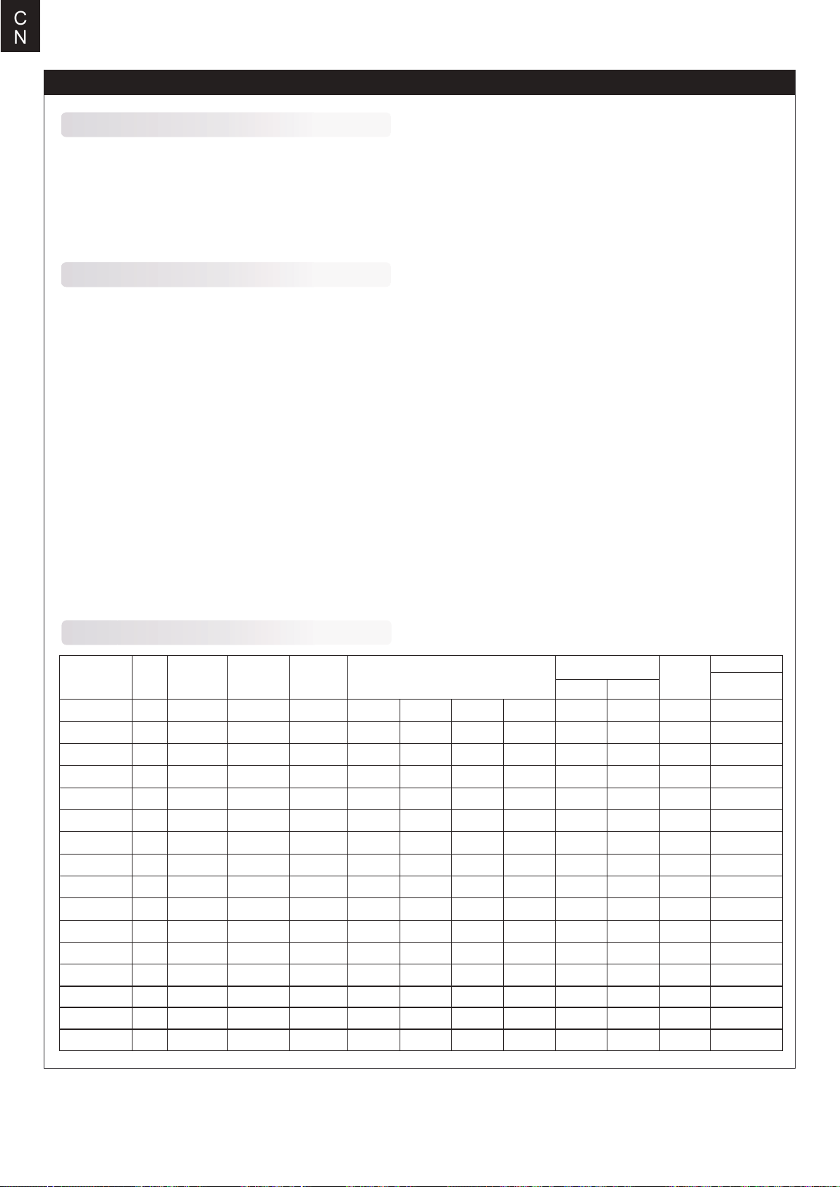
C
N
电调使用说明
产品特色
1. 所有器件均为原装正品,确保电调具有一流品质和极高的可靠性。
2. 具有强大的耐流能力。
3. 具备输入电压异常保护、电池低压保护、过热保护、油门信号丢失保护等多重保护功能。
4. 具有普通启动、柔和启动、超柔和启动三种启动模式,兼容固定翼飞机及直升机。
5. 可设定油门行程,兼容各种遥控器。具备平滑、细腻的调速手感,一流的调速线性。
6. 最高转速可以达 210000 RPM(2 极马达)、70000 RPM(6 极马达)、35000 RPM(12 极马达)。
产品功能简要说明
1. 刹车设定:无刹车/有刹车。
2. 电池类型:Lipo(锂电池)/ NiMH(镍氢)。
3. 电池低压保护模式:逐渐降低功率/立即关闭输出。
注:低压保护时,将油门摇杆拉到最小油门的位置后即可重新启动马达,但因为此时仍处于低压状况,所以功率输出较小。
4. 低压保护阈值:低/中/高。
1) 当电池类型设定为 Lipo 电池时,电调自动判断锂电节数,低/中/高情况下每节电池的截止电压分别为:2.85V/3.15V/3.3V。
例如:使用 3 节锂电,设定为中截止电压,则低压保护阈值为:3.15*3=9.45V。
2) 当电池类型设定为镍氢电池时,低/中/高情况下截止电压为开机时输入电压的 0%/50%/65%。0% 意味着不进行低压保护。
例如:使用 6 节镍氢电池,充满时电压为 1.44*6=8.64V,当设定为中截止电压时,则截止电压阈值为:8.64*50%=4.3V。
5. 启动模式:普通/柔和/超柔和启动,马达转速从静止到最高速度的时间分别为 300ms/1.5s/3s。
普通启动适用于固定翼,柔和启动/超柔和启动适用于直升机。柔和启动和超柔和启动的初始转速都比较低,即便瞬时将油门摇杆
推到最大位置,马达从静止到全速也分别需要 1.5 秒和 3 秒。
(注:启动过程结束后后若关闭油门,3 秒内再次启动,则均自动切换为普通模式,以免在特技飞行时因反应过慢而导致摔机)。
6. 进角:低/中/高,分别为 3.75 度 /15 度/26.25 度。
一般情况下,低进角可以适应较多的马达。但是因为马达结构差异很大,请试用各个进角以获得满意的驱动效果。为提高转速,可
以将进角设为高进角。改变进角后,建议先在地面进行测试,然后再飞行。
产品规格
型号
6A
12A
12AE
15A
20A
30A
40A
40A-UBEC
50A-UBEC
60A-UBEC
60A-OPTO
80A-UBEC
80A-OPTO
80A ESC
80Ax2+UBEC
100A ESC
持续电流瞬时电流
(10 秒)
6A
12A
12A
15A
20A
30A
40A
40A
50A
60A
60A
80A
80A
80A
80A
100A
8A
15A
15A
20A
25A
40A
55A
55A
65A
80A
80A
100A
100A
100A
100A
120A
BEC 类型BEC 输出BEC 驱动微型舵机能力
线性稳压2 节锂电3 节锂电4 节锂电6 节锂电2 节5-6 节5.5g32*12*4.5
线性稳压
线性稳压
线性稳压
线性稳压
线性稳压
线性稳压
开关稳压
开关稳压
开关稳压
无
开关稳压
无
开关稳压
开关稳压
开关稳压
5V/0.8A
5V/1A
5V/2A
5V/2A
5V/2A
5V/2A
5V/3A
5V/3A
5V/5A
5V/5A
无
5V/5A
无
5V/7A
5V/10A
5V/7A
3 个舵机
2 个舵机
5 个舵机
5 个舵机
5 个舵机
5 个舵机
5 个舵机
8 个舵机
8 个舵机
8 个舵机
2 个舵机
4 个舵机
4 个舵机
4 个舵机
4 个舵机
5 个舵机
8 个舵机
8 个舵机
8 个舵机
5 个舵机
6 个舵机
6 个舵机
6 个舵机
6 个舵机
6 个舵机
6 个舵机
电池节数
锂电镍氢
2-3 节5-9节
2-3 节5-9节
2-3 节5-9节
2-3 节5-9节
2-3 节5-9节
2-3 节5-9节
2-4 节5-12 节
2-4 节5-12 节
2-6 节5-18 节
2-6 节5-18 节
2-6 节5-18 节
2-6 节5-18 节
3-6 节5-18 节
3-6 节5-18 节
3-6 节5-18 节
重量
9g
10g
16.5g
19g
37g
39g
43g
41g
63g
60g
82g
79g
79g
175g
92g
体积
长*宽*高
(mm)
38*18*6
38*18*7
48*22.5*6
42*25*8
68*25*8
68*25*8
65*25*12
65*29*10
77*35*14
77*35*14
86*38*12
86*38*12
85*36*9
85*36*9
85*36*9
54
Page 41
首次使用您的无刷电子调速器
特别强调!为了让电调适应您的遥控器油门行程,在首次使用本电调或更换其他遥控器使用时,均应重新设定油门行程。
油门行程设定说明:
1. 开启遥控器,将油门打到最高点。
2. 将电调接上电池,等待2秒。
3.“哔-哔-”油门最高点确认音。
4. 将油门推到最低等待 1 秒。
5.N 声短鸣音表示锂电节数。
6.“哔 -”油门最低点确认音
7. 系统准备就绪可以起飞。
正常使用开机过程说明 :
1. 开启遥控器,将油门打到最低点。
2. 电调接上电池,鸣叫提示音符“ ♪123”,表示上电正常。
3. 发出N声短鸣音,表示锂电池节。
4. 自检 OK,发出长鸣音“哔⸺”系统准备就绪。
5. 推油门可随时起飞。
C
N
电调保护功能说明
1. 启动保护:当推油门启动后,如在两秒内未能正常启动马达,电调将会关闭马达,油门需再次置于最低点后,才可以重新启动。(出
现这种情况的原因可能有:电调和马达连线接触不良或有个别输出线断开、螺旋桨被其他物体阻挡、减速齿卡死等)。
2. 温度保护:当电调工作温度超过110 摄氏度时,电调会降低输出功率进行自我保护,但不会将输出功率全部关闭,最多只降到
全功率的 40%,以保证马达仍有动力,避免摔机。温度下降后,电调会逐渐恢复最大动力。
3. 油门信号丢失保护:当检测到油门遥控信号持续丢失1 秒后,电调开始降低输出功率,如果信号始终无法恢复,则一直降到零
输出(降功率过程为2 秒) 。如果在降功率的过程中油门遥控信号重新恢复,则立即恢复油门控制。优点:在油门信号瞬间丢失的
情况下(小于1 秒),电调并不会立即切断动力输出;如果遥控信号确实长时间丢失,则进行保护,但也不是立即关闭输出,而是
有一个逐步降低输出功率的过程,给玩家留有一定的时间救机,兼顾安全性和实用性。
4. 过负荷保护:当负载突然变得很大时,电调会切断动力,或自动重启。出现负载急剧增大的原因通常是马达堵转。
故障处理
故障现象
上电后电机无法启动,无任何声音电源接头接触不良
上电后电机无法启动, 发出“哔-哔-、
哔-哔-、哔-哔-”警示音(每两声之间
的间隔时间为 1 秒)
上电后电机无法启动, 发出“哔-、哔-、
哔 -”警示音(每声之间的间隔时间为 2 秒)
电池组电压不正常
接收机油门通道无油门信号输出
可能原因解决方法
重新插好接头或更换接头
检查发射机和接收机的配合是否正常,
油门控制通道接线是否插紧
检查电池组电压
上电后电机无法启动, 发出“哔、哔、哔、
哔、哔”急促单音
上电后电机无法启动, 发出“哔-哔-”
提示音,然后发出“56712 ”特殊提示音
电机反转
油门未归零或油门行程设置过小
油门通道“正/反”向错误
电调输出线和电机线连接的线序错误
55
将油门摇杆置于最低位置;重新设置
油门行程
参考遥控器说明书,调整油门通道的
“正/反”向设置
将三根输出线中的任意两根对调
Page 42
C
N
遥控器编程设定说明
注意:务必检查遥控器中油门曲线的设置,确保摇杆最低点位置对应的油门输出值为 0,最高点位置对应输出值为 100%。
一、进入编程模式
1. 开启遥控器,将油门打到最高,电调接上电池。
2. 等待2秒,马达鸣叫“哔 -哔 -”提示音。
3. 再等待5秒,马达鸣叫“ 56712”特殊提示音,表示已经进入编程模式。
二、选择设定项
进入编程设定后,会听到8种鸣叫音,按如下顺序循环鸣叫,在鸣叫某个提示音后,3 秒内将油门打到最低,则进入该设定项。
提示音
“哔”(1 短音)
“哔-哔-”(2 短音)
“哔-哔-哔-”(3 短音)
“哔-哔-哔-哔-”(4 短音)
“哔⸺”(1 长音)
“哔⸺哔 -”(1长1短)
“哔⸺哔-哔-”(1长2短)
“哔⸺哔⸺””(2 长音)
注:一长音“哔⸺”相当于 5 声短音“哔 -”,所以在“选择设定项”中,一长一短的“哔⸺哔-”表示第 6 选项,以此
设定项
刹车
电池类型
低压保护模式
低压保护阈值
启动模式
进角
恢复出厂默认值
退出
三、选择参数值
马达会循环鸣叫,在鸣叫某个提示音后将油门摇杆打到最高点,则选择该提示音所对应的设定值,接着鸣叫特殊提示音“1515 ”,
表示该参数值已被保存。(此时如果不想再设定其它选项,则在2秒内将油门摇杆打到最低,即可快速退出编程设定模式;如果还
要设定其它选项,则继续等待,退回第二步骤,再选择其它设定项)。
设定项
提示音“哔 -”
1 声
“哔-哔-”
2 声
“哔-哔-哔-”
3 声
刹车
电池类型
低压保护方式
低压保护阈值
启动模式
进角
无刹车
锂电池
逐渐降低功率
低
普通模式
低
有刹车
镍氢电池
立即关闭动力
中
柔和启动
中
高
超柔和启动
高
四、退出设定
有如下两种方式退出设定:
1. 在第三步骤,选择设定值时,鸣叫特殊提示音“ 1515”后,2 秒内将油门摇杆打到最低点,则退出设定。
2. 在第二步骤,选择设定项时,当电机鸣叫出“哔⸺哔⸺”(即第 8 个设定项)两长音后,3 秒内将油门打到最低点,则退出设定。
56
Page 43
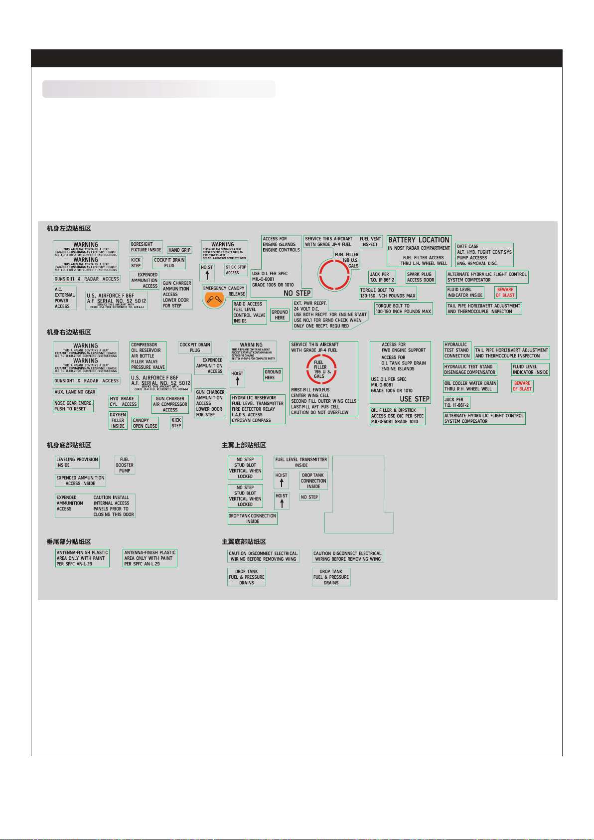
Decal Application
贴纸应用
WATER DECAL APPLICATION水贴粘贴步骤
1. Cut decals from the sheet as needed.
2. Dip the decal in water for about 15-30 seconds.
3. Hold the decal backing sheet edge and gently slide the decal onto the model in its proper position .
4. Using a cotton stick gently push out the water and bubbles from inside.
1. 剪下所需水贴纸。
2. 将水贴纸浸入水中约15-30秒
3. 压住水贴纸背片的边缘,将水贴纸滑动到模型的适当位置。
4. 用棉棒挤出里面的水份和气泡。
A1
A2
A3
B1
B2
B3
B4
C1E1
C2
C3
A4
A5
A6
A7
A8
A10
B5
B6
B7
B8
C4
B9
B10
B11
A9
B12
A11
A12A13
A14
B13
B14
A16
A18
A15
B15
B16
E2
E3
A17
B19B20
B18
B17
E4
E5
E6
E7
E9
A19
SERVICE THIS AIRCRAFT
WITH GRADE JP-4 FUEL
FIRST-FILL FWD.FUS.
CENTER WING CELL
E8
SECOND FILL OUTER WING CELLS
LAST-FILL AFT. FUS CELL
CAUTION DO NOT OVERFLOW
A21
A22
B21
FUEL
FILLER
196 U S.
GALS
A20
A24
A23
A25
A26
A27
A28
B22
B23
B24
B25
B26
A29
B27
B28
B29
D1D2
F1
F2
F3
F4
57
Page 44
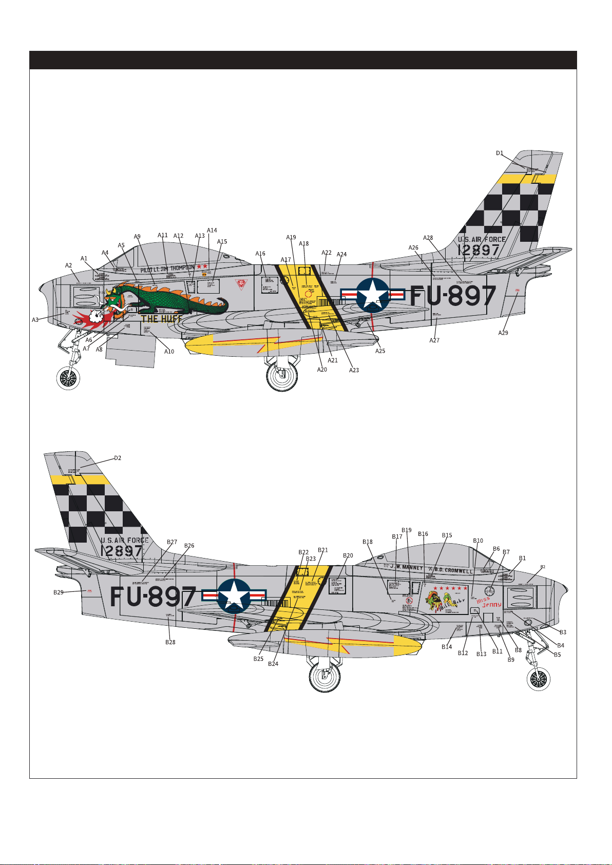
Decal Application
贴纸应用
58
Page 45
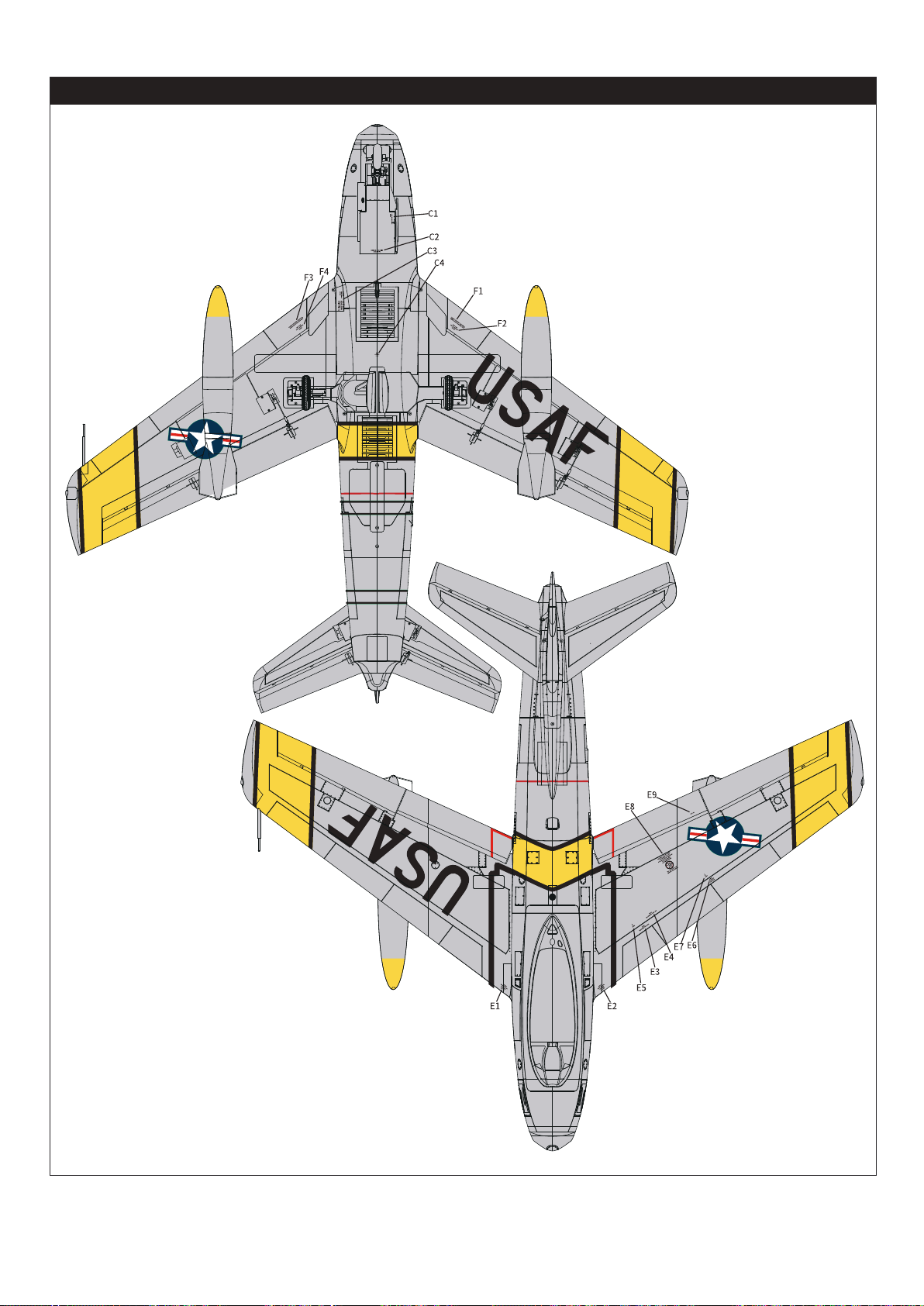
Decal Application
贴纸应用
59
Page 46

Foshan Zhengze Model Technology Co., Ltd.
Tel:+86-0757-26330080
E-mail:[email protected]
Add: Unit A, Building 6, Jicheng Science and Technology Innovation Park,
Shunde, Foshan City, Guangdong Province, 528306
佛山市正泽模型科技有限公司
电话:86-0757-26330080
地址及电话:广东省佛山市顺德区北滘镇顺江社区三乐东路25号集成科创园 6栋
中国代理
车模
酷乐派模型 KLP Racing
蓝飞驰模型
老顽童模型
顶尖遥控模型
苏乐快捷模型
意帆模型 Well Model
航模
苏州雷飞航模车模
擎天模型
神鹰模型
mymtt的新店
天天向上模型
新动模型
MADE IN CHINA
 Loading...