

Page 1
64MM F-18
HORNET V2
SIMPLE RIGID
SIMPLE ASSEMBLY STRONG DURABLE EPO
STABLE
SMOOTH FLYING PERFORMANCE
FMSMODEL.COM
Page 2

Page 3
Page 4
Table of Contents
Introductions
Contents of Kit
Model Assembly
Battery and radio installation
Get your model ready to fly
The transmitter and model setup
Check the control throws
Clevis Installation
Control Horn and Servo Arm Settings
Center of Gravity(CG)
Before flying the model
Flying Course
Trouble shooting
Spare parts list content
ESC instruction
··························································································································3
························································································································4
······················································································································5
·····································································································9
·····································································································10
······························································································10
········································································································11
··················································································································12
·························································································12
·············································································································13
············································································································14
·······················································································································15
····················································································································16
···········································································································17
·····················································································································18
Introductions
FMS is pleased to announce that all 64mm ducted fan aircrafts are being upgraded. Inspired by the superior
features of the original model, F-18 version two (V2) has improved mechanical and structural features that will
enhance air performance and decrease assembly time.
The fiber pipe greatly enhances the wing strength for enhanced flying maneuvers. Improved main wing set and
landing gear installation optimizes strength of structure and reduces assembly time.
The latest 64mm ducted fan can achieve more than 800 grams of thrust.
The differences in speeds between the V1 and V2 will be noticeable. If you possess the “need for speed,”
accessories such as missiles can be removed to create a faster more streamlined model.
Upgrades
495mm fiber pipe inserted through the fuselage and main wing
Use of four inner-hexagon screws instead of glue improves main wing set and landing gear installation optimizing
strength of structure.
New more powerful 64mm 11-blade ducted fan with up to 800 grams of thrust.
New 2840-KV3150 motor
New Predator 40A ESC
The latest FMS EPO foam material creates stronger, more impact-resistant planes.
Environmentally friendly water-based paint minimizes blistering from sun.
Pre-installed newly designed control horns allows more throw.
Features
350mm fiber pipe inserted through the fuselage and main wing
Improved main wing set and landing gear installation. optimizes strength of structure and reduces assembly time.
64mm 11-blade ducted fan
2840-KV3150 motor
Predator 40A ESC
5x 9g servos
The latest EPO foam material creating stronger, more impact-resistant plane.
Environmentally friendly water-based paint minimizes blistering from sun.
Pre-installed newly designed control horns allows more throw.
3
Page 5
Wingspan: 675mm (26.6in)
Overall Length: 934mm (36.8in)
Flying Weight: Around 1000g (35.3 oz)
Motor Size: Brushless 2840-KV3150
Wing Load: 81.3 g/dm² (0.19 oz/in²)
Wing Area: 12.3 dm² (190.7 sq.in)
ESC: 40A
Servo: 9g Servo x 5
Contents of Kit
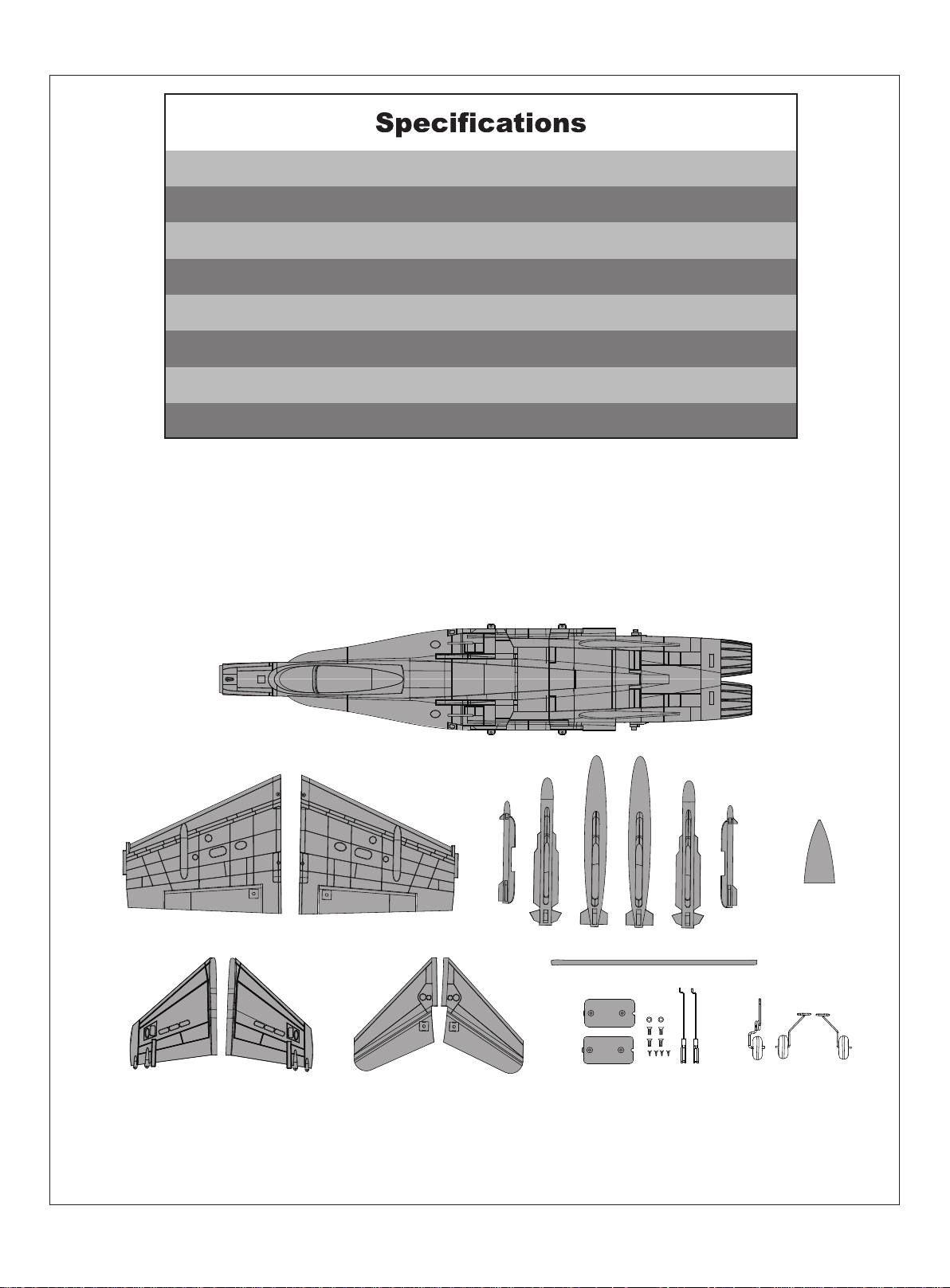
Before assembly , please inspect the contents of the kit. The photo below details the contents of the kit and
labels. If any parts are missing or defective, please indentify the name or part number (refer to the spare
parts list near the end of the manual) then contact your local shop or email us: [email protected]
A.
B.
C. D.
E.
F.
G.
H. I.
A: Fuselage
B: Main wing
C: Vertical Stabilizer(Left and Right)
D: Horizontal Stabilizer (Left and Right)
E: Missile Set
F: Nose Cone
G: Fiber Pipe
H: Linkage and Screws
(4-HKM3.0*10, 4-KA2.0*8)
I: Landing Gear Set
4
Page 6
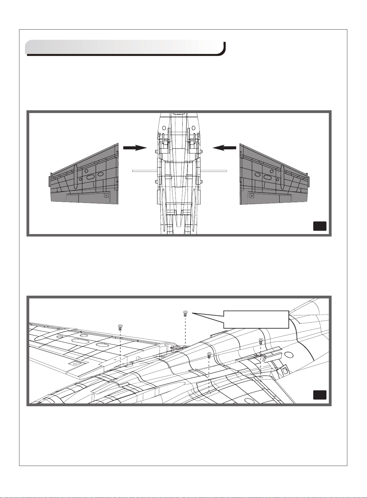
Model Assembly
Main Wing Installation
1.Slide the wing tube into the fuselage (fig1).
2.Install the left and right wing over the wing tube and into the wing slot of the fuselage (fig1).
fig1
3.Secure the left and right wing to the fuselage using the 4 screws included (fig2)
HKM3.0*10
fig2
5
Page 7
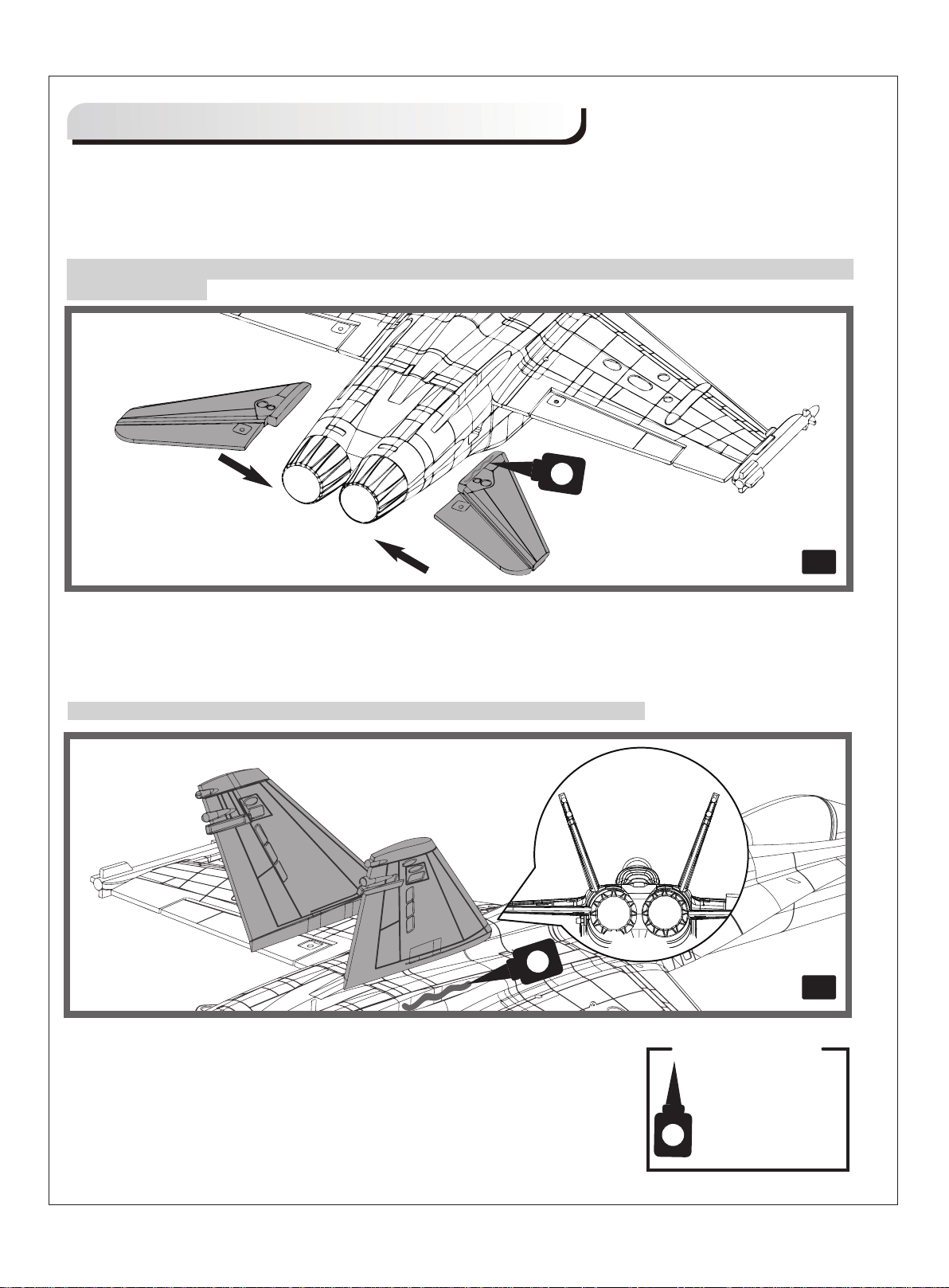
Model Assembly
Horizontal Stabilizer Installation:
Carefully apply CA to the base and the side of the rear fuselage slot. Install the stabilizer into the place.
Ensure the control horn faces down as shown (fig3)
Note: Ensure the stabilizer horizontal axis is parallel to the wing. Adjust any misalignment before the glue
dries thoroughly.
fig3
Vertical Stabilizer Installation:
Carefully apply CA to the top rear fuselage slots. Install the vertical stabilizer into place.
Note: the vertical stabilizer will angle towards the outboard of the plane (fig4).
Required Adhesives:
fig4
6
Foam Safe Medium CA
Page 8
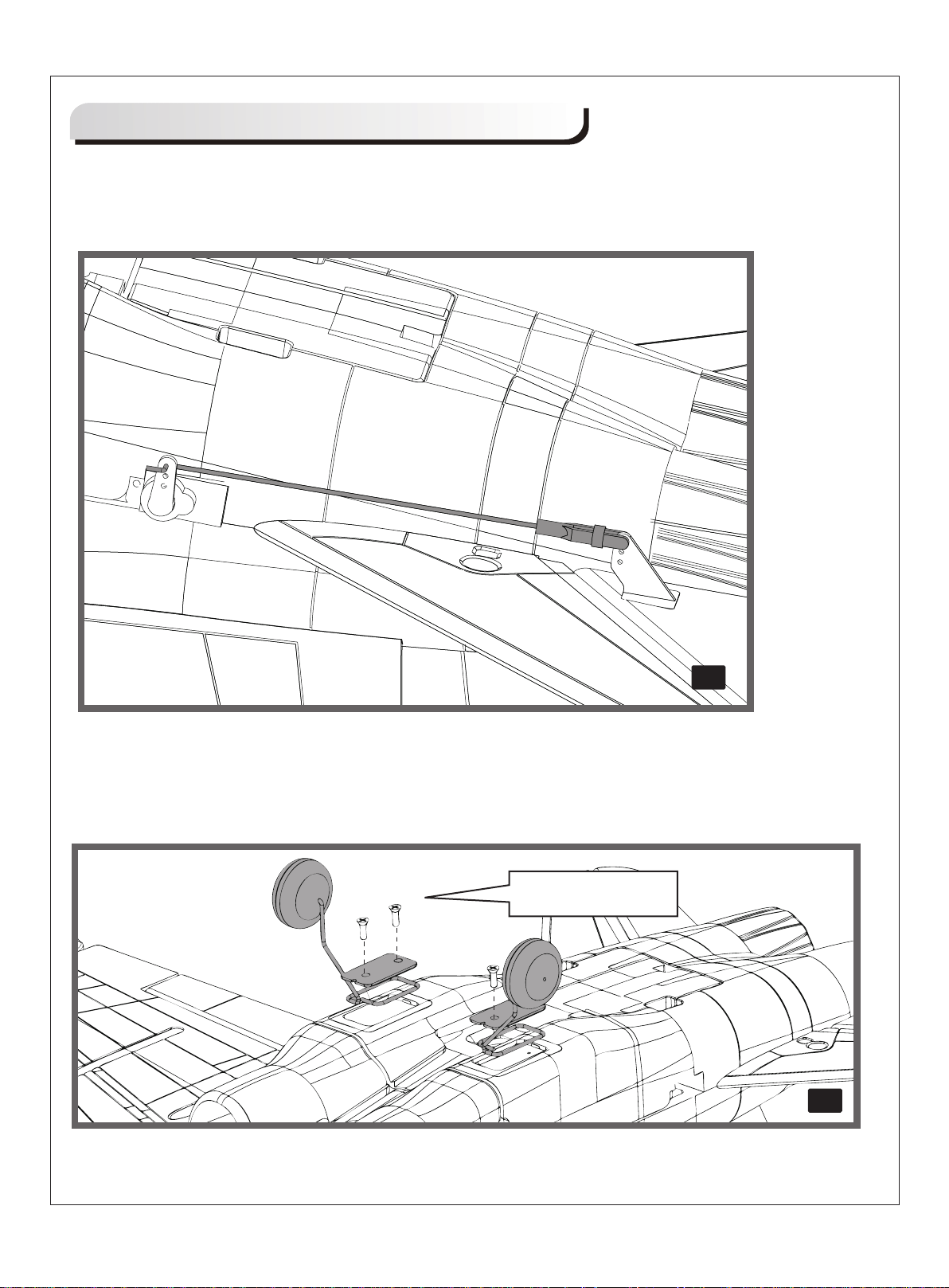
Model Assembly
Clevis Installation:
Install the clevis. (fig5) Refer to the Clevis Installation on page 12.
Landing Gear Installation:
Install landing gear with the included screws (fig6).
fig5
KA2.0*8
fig6
7
Page 9
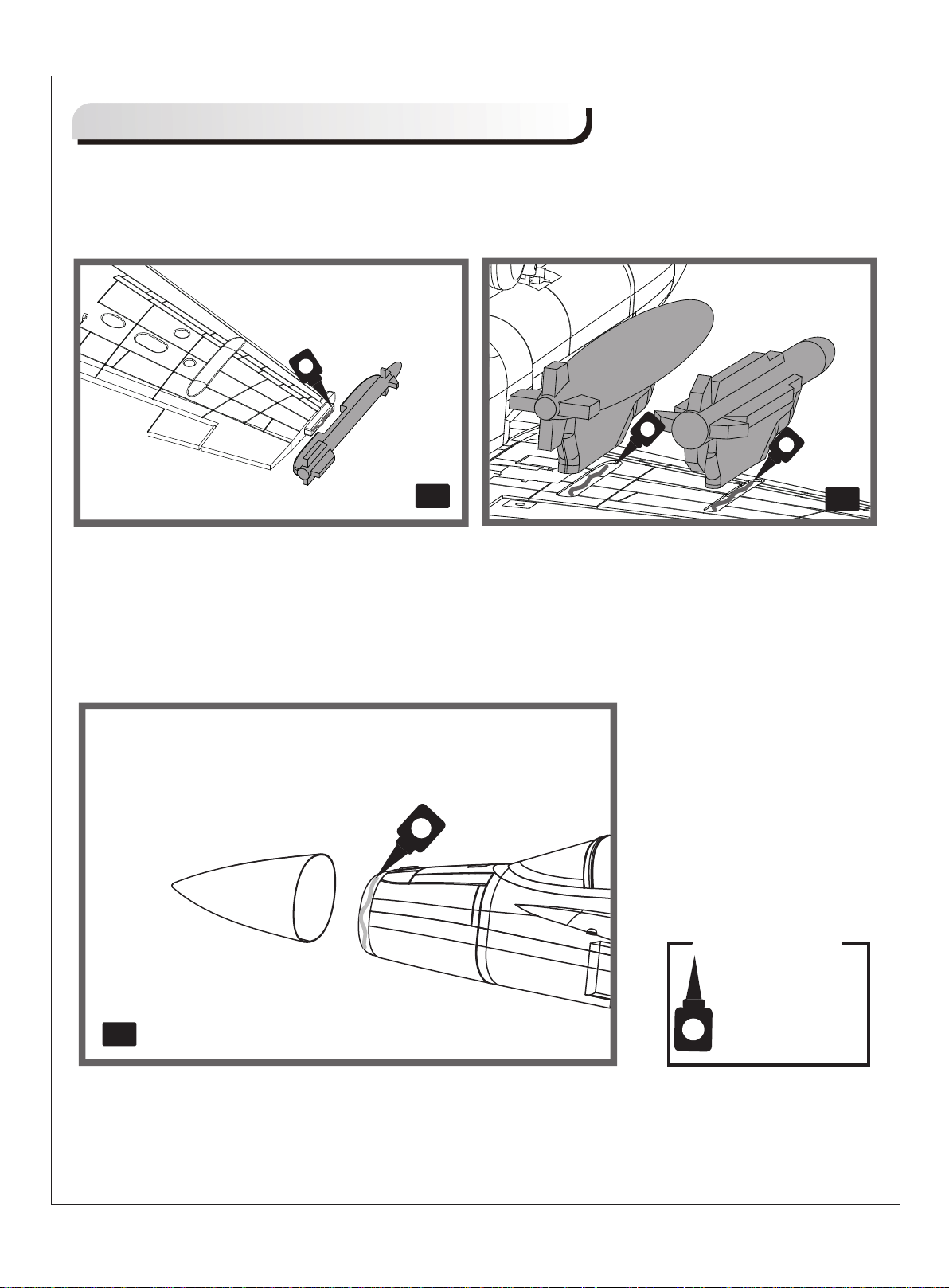
Model Assembly
Missiles Installation:
Correctly mount the wing missiles with CA. (fig7/fig8)
fig7
Nose Cone Installation:
Apply the nose cone to the front fuselage as diagram shows. Ensure the nose cone is on the correct
side.(fig 9)
Required Adhesives:
fig8
fig9
Foam Safe Medium CA
8
Page 10
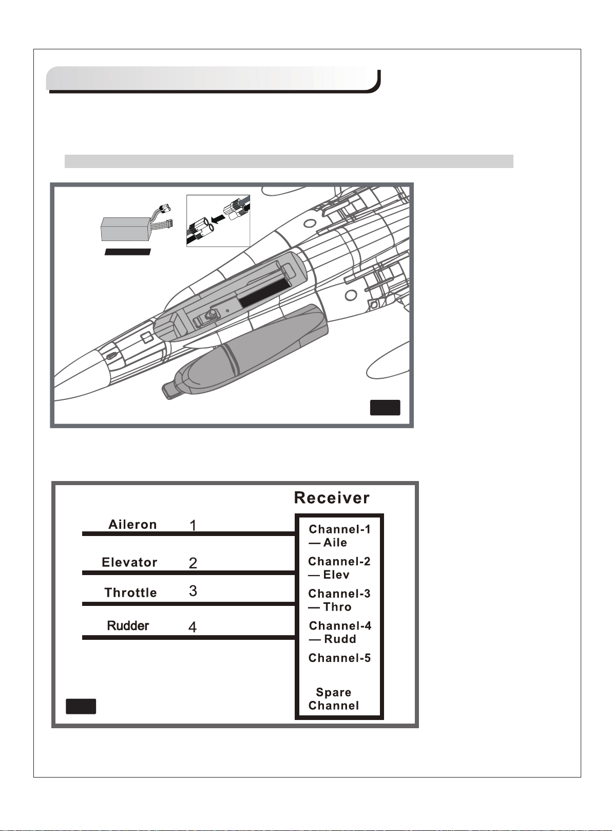
Battery and radio installation
1. Apply the hook tape to the cable end of the battery (fig 10).
2. Slide the battery into the battery compartment with the power supply cable toward the fore-end
of the plane.
Note: you may need to relocate the battery position to achieve the correct CG for your model.
3. Check the connection diagram below for more information (fig11.)
fig10
fig11
9
Page 11
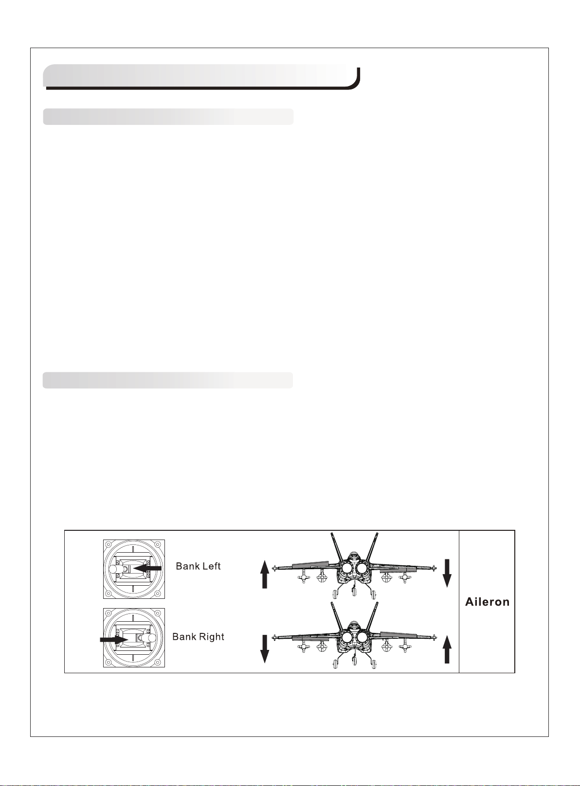
Get your model ready to fly
Important ESC and model information
The ESC included with the model has a safe start. If the motor battery is connected to the ESC and the
1.
throttle stick is not in the low throttle or off position, the motor will not start until the throttle stick is moved to
the low throttle or off position. Once the throttle stick is moved to the low throttle or off position, the motor will
emit a series of beeps. Several beeps with the same tune means the ESC has detected the cells of the
battery. The count of the beeps equals the cells of the battery. The motor is now armed and will start when
the throttle is moved.
The motor and ESC come pre-connected and the motor rotation should be correct. If for any reason the
2.
motor is rotating in the wrong direction, simply reverse two of the three motor wires to change the direction
of rotation.
The motor has an optional brake setting. The ESC comes with brake switched off and we recommend that
3.
the model be flown with the brake off. However, the brake could be accidentally switched on if the motor
battery is connected to the ESC while the throttle stick is set at full throttle. To switch the brake off, move the
throttle stick to full throttle and plug in the motor battery . The motor will beep one time. Move the throttle stick
to low throttle or the off position. The motor is ready to run and the brake will be switched off.
Battery Selection and Installation. We recommend the 14.8V 2600mAh 4S 35C Li-Po battery. If using
4.
another battery, the battery must be at least a 14.8V 2600mAh 4S 35C battery. Your battery should be
approximately the same capacity, dimension and weight as the 14.8V 2600mAh 4S 35C Li-Po battery to fit
the fuselage without changing the center of gravity significantly.
The transmitter and model setup
Before getting started, bind your receiver with your transmitter. Please refer to your Transmitter Manual for
proper operation
CAUTION: To prevent personal injury, DO NOT install the propeller assembly onto the motor shaft while
testing the control surfaces. DO NOT arm the ESC and do not turn on the transmitter until the Transmitter
Manual instructs you to do so.
Tips: Make sure all control sticks on your radio are in the neutral position (rudder, elevator , ailerons) and the
throttle is in the OFF position. Make sure both ailerons move up and down (travel) the same amount. This
model tracks well when the left and right ailerons travel the same amount in response to the control stick.
1. Move the controls on the transmitter to make sure the aircraft control surface moves correctly. See
diagrams below.
10
Page 12
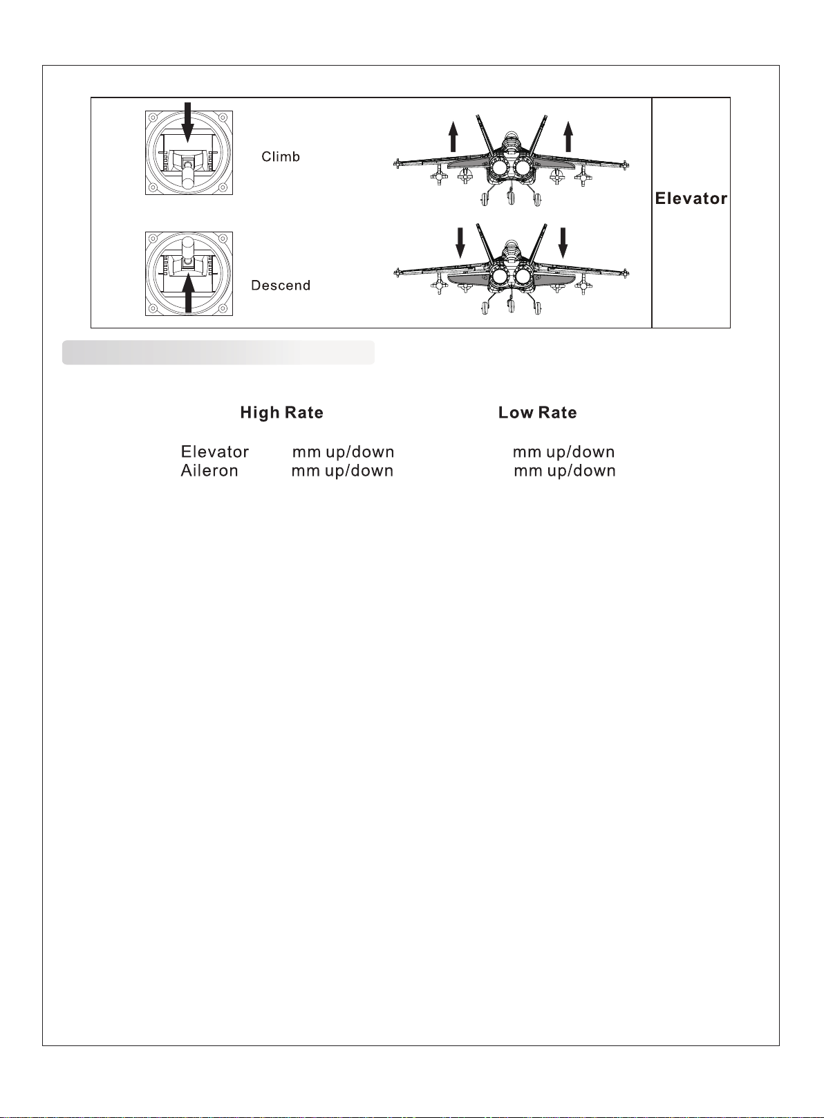
Check the control throws
The suggested control throw setting for FMS MODEL are as follows (dual rate setting):
14
12
Tips: On first flight, fly the model in low rate. The first time you use high rates, be sure to fly at low to medium
speeds. High rate, as listed, is only for EXTREME maneuvering.
10
8
11
Page 13
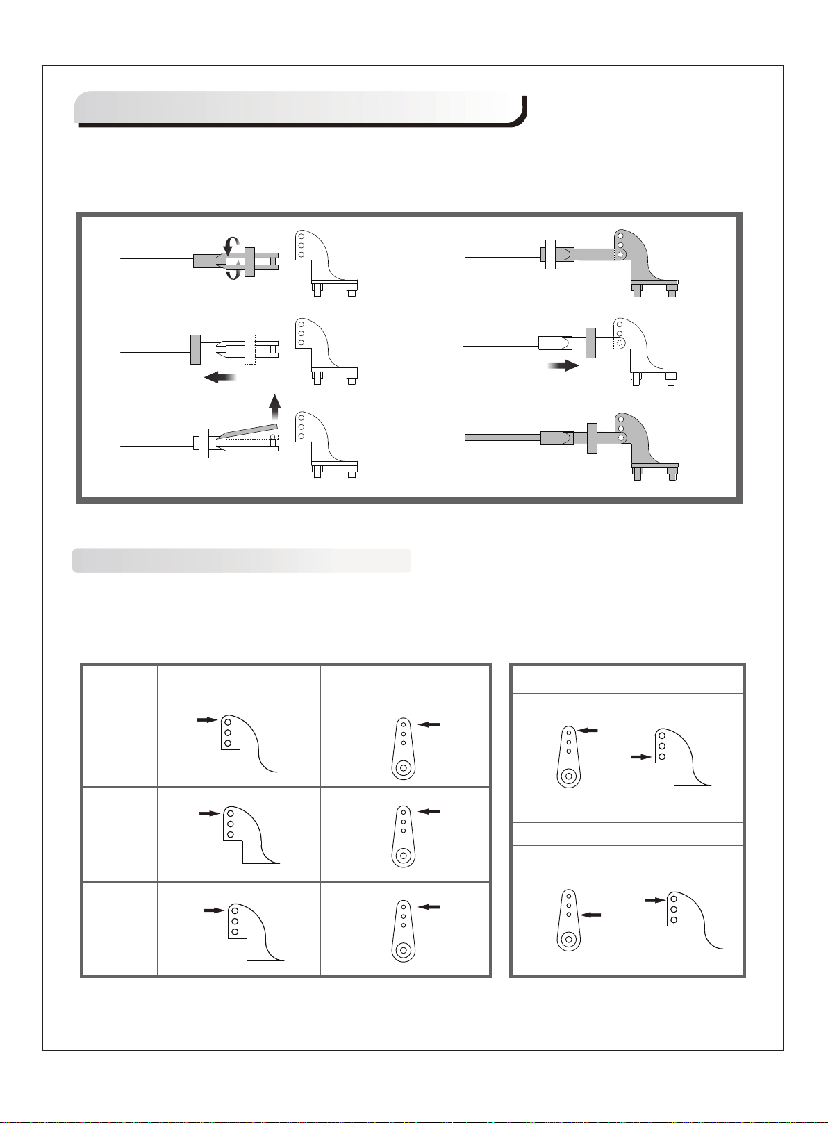
Clevis Installation
a. Pull the tube from the clevis to the linkage.
b. Carefully spread the clevis, then insert the clevis pin into the desired hole in the control horn.
c. Move the tube to hold the clevis on the control horn.
a.
b.
c.
d.
e.
f.
Control Horn and Servo Arm Settings
The table shows the factory settings for the control horns and servo arms. Fly the aircraft at the factory
settings before making changes.
After flying, you may choose to adjust the linkage positions for the desired control response. See the table
to the below
Elevator
Rudder
Ailerons
Horns Arms
12
More control throw
Less control throw
Page 14
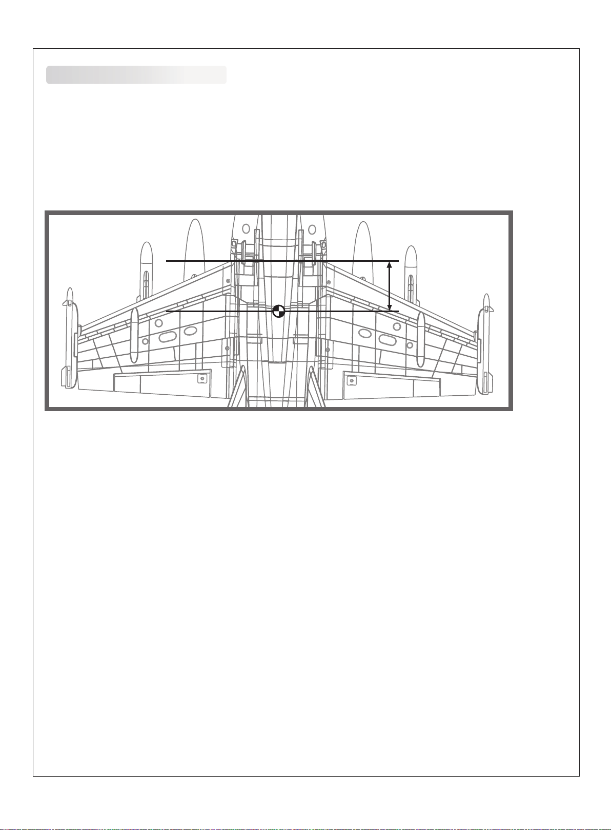
Check the C.G. (Center of Gravity)
When balancing your model, adjust the motor battery as necessary so the model is level or slightly nose down.
This is the correct balance point for your model. After the first flights, the CG position can be adjusted for your
personal preference.
1. The recommended Center of Gravity (CG) location for your model is (80-85mm) forward from the leading
edge of the main wing (as shown) with the battery pack installed. Mark the location of the CG on top of the
wing.
2. When balancing your model, support the plane at the marks made on the bottom of the main wing with your
fingers or a commercially available balancing stand. This is the correct balance point for your model. Make sure
the model is assembled and ready for flight before balancing.
80-85mm
13
Page 15
Before flying the model
Find a suitable flying site
Find a flying site clear of buildings, trees, power lines and other obstructions. Until you know how much area
will be required and have mastered flying your plane in confined spaces, choose a site which is at least the
size of two to three football fields - a flying field specifically for R/C planes is best. Never fly near people especially children, who can wander unpredictably.
Perform the range check for your plane
As a precaution, an operational ground range test should be performed before the first flight each time you go
out. Performing a range test is a good way to detect problems that could cause loss of control such as low
batteries, defective or damaged radio components, or radio interference. This usually requires an assistant
and should be done at the actual flying site you will be using.
First turn on the transmitter, then install a fully-charged battery into the fuselage. Connect the battery and
install the hatch.
Remember, use care not to bump the throttle stick. Otherwise, the propeller/fan will turn and possibly cause
damage or injury.
Note: Please refer to your Transmitter Manual that came with your radio control system to perform a ground
range check. If the controls are not working correctly or if anything seems wrong, do not fly the model until
you correct the problem. Make certain all the servo wires are securely connected to the receiver and the
transmitter batteries have a good connection.
Monitor your flight time
Monitor and limit your flight time using a timer (such as on a wristwatch or in your transmitter if available).
When the batteries are getting low you will usually notice a performance drop before the ESC cuts off motor
power, so when the plane starts flying slower you should land. Often (but not always) power can be briefly
restored after the motor cuts off by holding the throttle stick all the way down for a few seconds.
To avoid an unexpected dead-stick landing on your first flight, set your timer to a conservative 4 minutes.
When your alarm sounds you should land right away.
14
Page 16
Flying course
Take off
While applying power, slowly steer to keep the model straight. The model should accelerate quickly. As the
model gains flight speed you will want to climb at a steady and even rate. It will climb out at a nice angle of
attack (AOA).
Flying
Always choose a wide-open space for flying your plane. It is ideal for you to fly at a sanctioned flying field. If
you are not flying at an approved site always avoid flying near houses, trees, wires and buildings. You should
also be careful to avoid flying in areas where there are many people, such as busy parks, schoolyards, or
soccer fields. Consult laws and ordinances before choosing a location to fly your aircraft. After takeoff, gain
some altitude. Climb to a safe height before trying technical manoeuvres, including high speed passes,
inverted flight, loops, and point rolls.
Landing
Land the model when you hear the motor pulsing (L VC) or if you notice a reduction in power . If using a transmitter
with a timer, set the timer so you have enough flight time to make several landing approaches.
Recharge the battery and repair the model as needed .The model’s three point landing gear allows the model
to land on hard surfaces. Align model directly into the wind and fly down to the ground. Fly the airplane down
to the ground using 1/4-1/3 throttle to keep enough energy for proper flare. Before the model touches down,
always fully decrease the throttle to avoid damaging the propeller or other components. The key to a great
landing is to manage the power and elevator all the way to the ground and set down lightly on the main landing
gear. After a few flights you will find the model can be set down lightly on the mains and you can hold the nose
wheel off balancing the model on the mains until it slows and gently settles the nose.
Maintenance
Repairs to the foam should be made with foam safe adhesives such as hot glue, foam safe CA, and 5min
epoxy. When parts are not repairable, see the Spare Parts List for ordering by item number.
Always check to make sure all screws on the aircraft are tightened. Pay special attention to make sure the
spinner is firmly in place before every flight.
15
Page 17
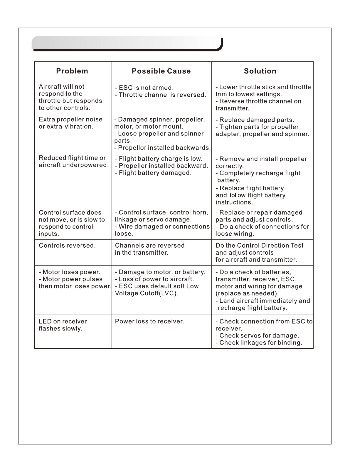
Troubleshooting
16
Page 18
Spare parts list content
FMSPY101
FMSPY102
FMSPY103
FMSPY104
FMSPY105
FMSPY106
FMSPY107
FMSPY108
FMSPY109
FMSPY110
FMSPY111
FMSPY112
FMSPY113
FMS64MM11B
FMSKV3150
PRESC009
FMSSER9GP
FMSSER9GR
FMSSER9G54
Fuselage
Main Wing Set
Rudder
Elevator
Missle-1
Missle-2
Oil Tank
Canopy
Cowl
Landing Gear Set
Linkage Rod
Pipe
Decal Sheet
64mm Ducted Fan
2840-KV3150 Motor
40A ESC (With 430mm length input cable)
9g Servo Positive
9g Servo Reverse
9g Servo 54 Degree
Visit our website to see photos of this product: www.fmsmodel.com
17
Page 19
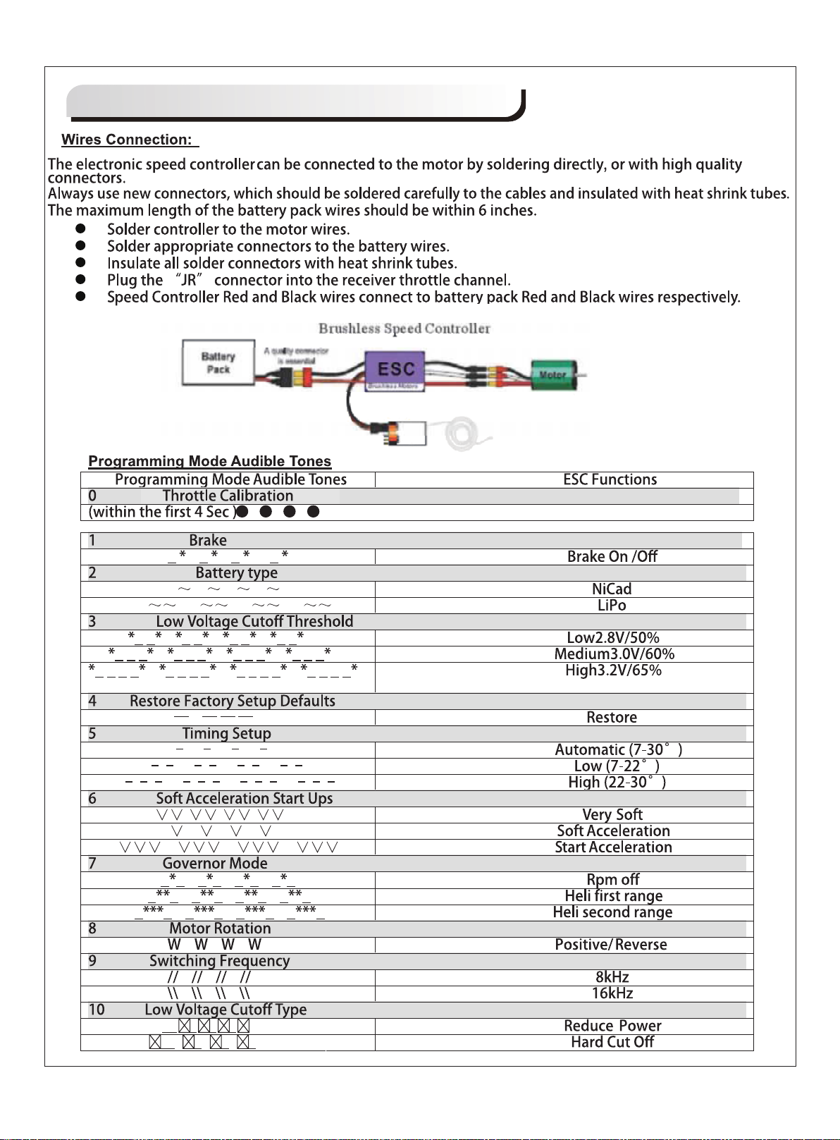
ESC instruction
18
Page 20

 Loading...