

Page 1
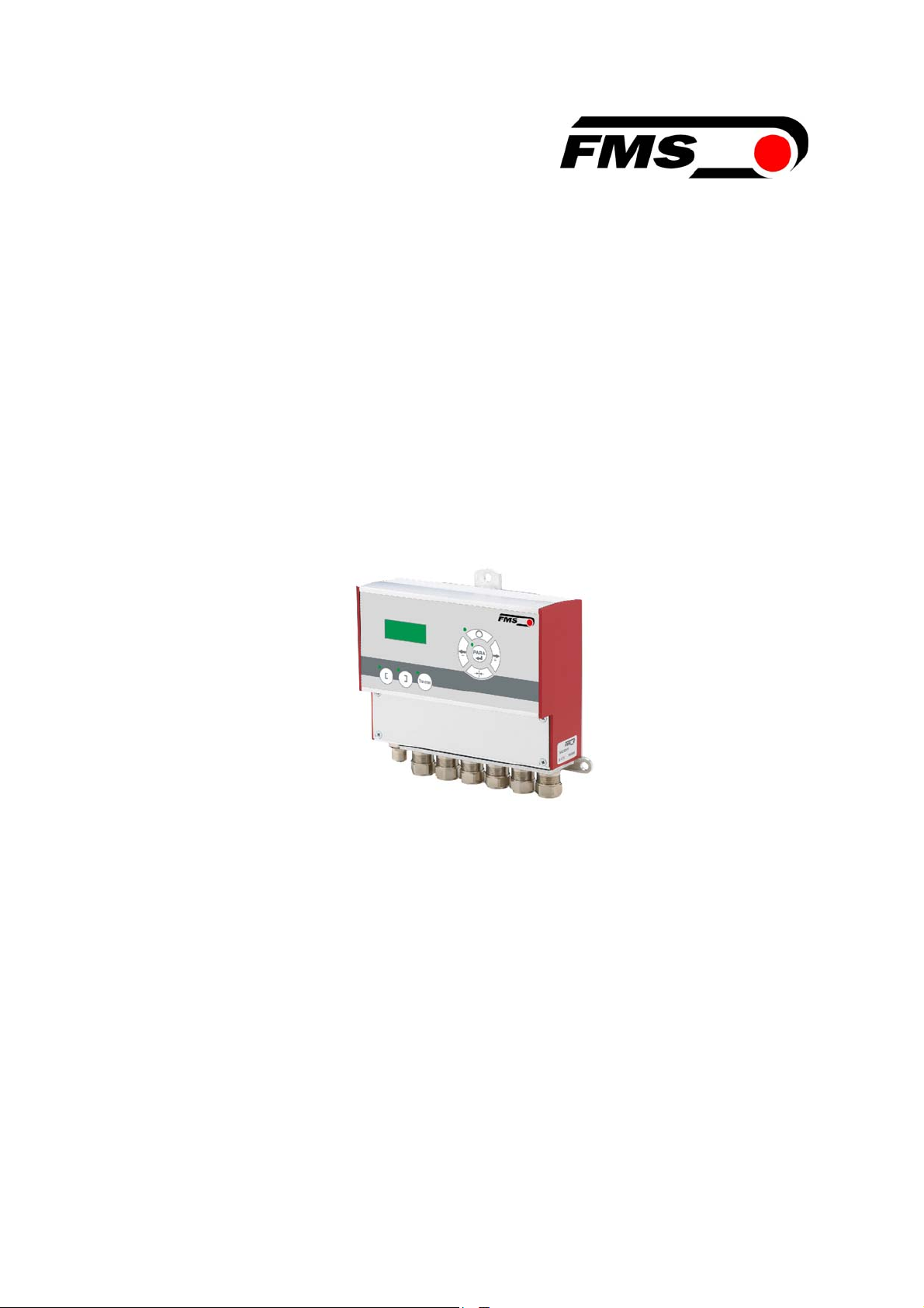
Operating Manual BKS309.MS
Digital Web Guide Controller
with Master-Slave Function
Version 2.40 08/2018 NS
Firmware Version V2.43
© by FMS Force Measuring Systems AG, CH-8154 Oberglatt – All rights reserved.
Page 2

Operating Manual BKS309.MS
Table of Contents
1 Safety Instructions ..................................................................................... 4
1.1 Description Conditions 4
1.2 List of Safety Instructions 4
2 System Description .................................................................................... 5
2.1 Functional Description Standard Web Guide Controller 5
2.2 Web Guide Controller with Master-Slave Functionality 5
2.3 Steering Frame or Actuator 6
2.4 Electronic Control Unit 6
2.5 Sensors 6
3 Quick Installation Guide ............................................................................ 7
3.1 Preparations for Set-up 7
3.2 Installation Procedure 7
3.3 Adjustment of the Sensors 7
4 Installation .................................................................................................. 8
4.1 Mounting the Steering Frame 8
4.2 Mounting the Actuator to your Unwind or Rewind Station 8
4.3 Mounting the Sensors 8
4.4 Mounting the Electronic Control Unit 9
5 Wiring Diagrams ....................................................................................... 10
5.1 Wiring a Steering Frame with BKS309.R / .S or .W Controller 10
5.2 Connecting webMASTERs BKS015 or BKS020 11
5.3 Connecting a winderGLIDE BKS.D.3 or a webMASTER BKS030 11
5.4 Connecting a winderGLIDE BKS.D.6 11
6 Configuring the System ........................................................................... 13
6.1 Power up the BKS 309.MS 13
6.2 Relays Outputs 14
6.3 Digital Inputs 14
6.4 Differences between Standard and Master-Slave Electronics 15
7 Operation .................................................................................................. 16
7.1 Operation Panel 16
7.2 Operating the Web Guiding System via the Front Panel 16
7.3 Automatic Operation 17
7.4 Manual Operation 18
7.5 Saving the Travel Limits 18
8 Parameter Setting over the Front Panel ................................................ 19
8.1 Basic Instructions for Parameter Setting 19
8.2 Setting of Operation Parameters 19
8.3 Setting of System Parameters 24
8.4 List of Operation Parameters 25
8.5 Description Operation Parameter 27
14.08.2018 2
Page 3

Operating Manual BKS309.MS
8.6 Setting of System Parameters 38
8.7 Reset to Default Parameter Set 40
9 Parameter Setting via a PC ..................................................................... 41
9.1 Parameterization in a Network via Web Browser 42
9.2 Parameterization via a PC (peer-to-peer connection) 47
10 Mechanical Dimensions .......................................................................... 51
11 Trouble Shooting ...................................................................................... 54
12 Technical Specification ............................................................................ 55
14.08.2018 3
Page 4
Operating Manual BKS309.MS
1 Safety Instructions
1.1 Description Conditions
a) Danger of health injury or loss of life
Danger
This symbol refers to high risk for persons to get health injury or loss life. It has to
be followed strictly.
b) Risk of damage of machines
Caution
This symbol refers to information, that, if ignored, could cause heavy mechanical
damage. This warning has to be followed absolutely.
c) Note for proper function
Note
This symbol refers to an important information about proper use. If not followed,
malfunction can be the result.
1.2 List of Safety Instructions
Some contacts on the power supply board are under 230V tension! Mortal danger!
Disconnect power supply before open the housing!
Proper function of the FMS web guide is only guaranteed with the recommended
application of the components. In case of other arrangement, heavy malfunction
can be the result.
Local installation regulations are to preserve safety of electric equipment. They are
not taken into consideration by this operating manual. However, they have to be
followed strictly.
Bad earth connection may cause electric shock to persons, malfunction of the total
system or damage of the control unit! It is vital to ensure that proper earth
connection is done.
The processor board is mounted directly behind the operation panel. Improper
handling of the electronic boards may cause damage to the fragile equipment!
Don’t use rough tools such as screwdrivers or pliers! Operators handling the
electronic boards must wear a well earthed bracelet in order to discharge static
electricity
14.08.2018 4
Page 5
Operating Manual BKS309.MS
2 System Description
2.1 Functional Description Standard Web Guide Controller
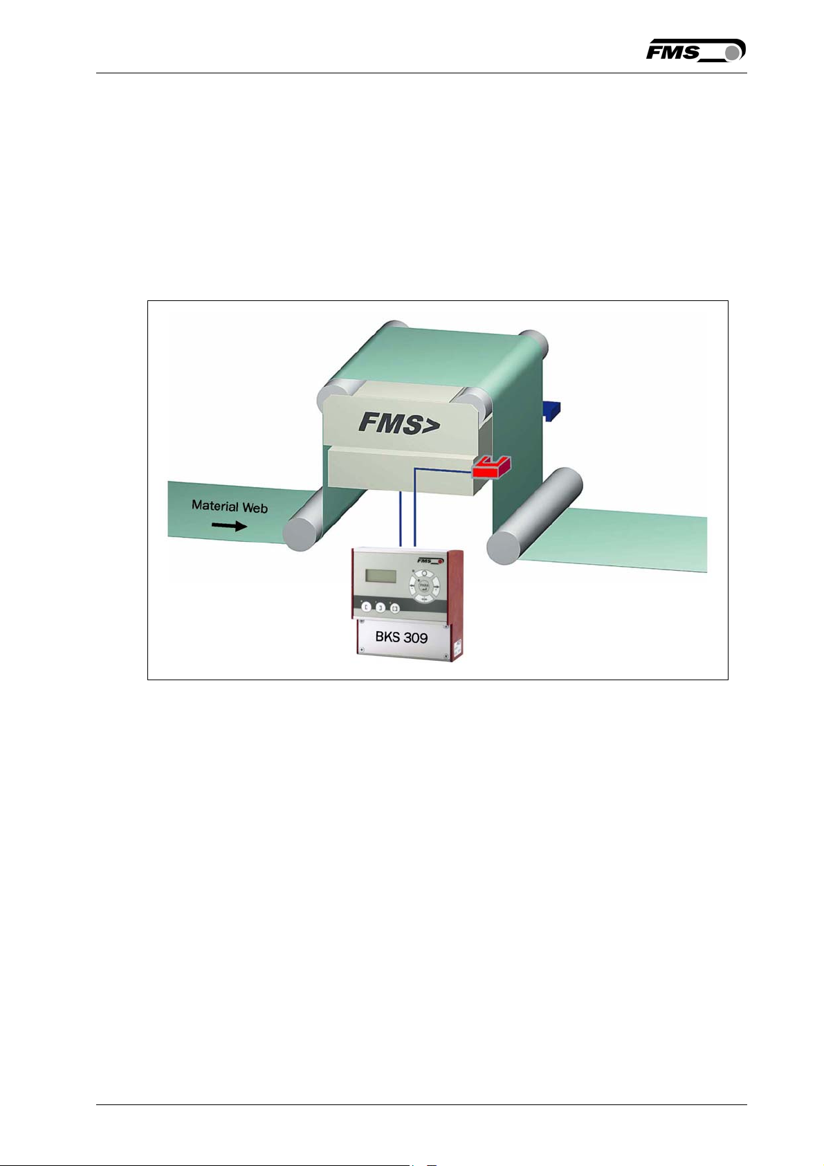
Figure 1 shows a typical web guiding system with its basic components.
The sensors measure the position of the web edge and send this information as an
analogue signal to the web guide controller BKS309. This electronics compares the
position feedback signal with the reference. If the difference of these two values is
higher then the stored dead band value, the steering frame will be adjusted.
Fig. 1: Basic system arrangement with BKS309 web guide controller K309003e
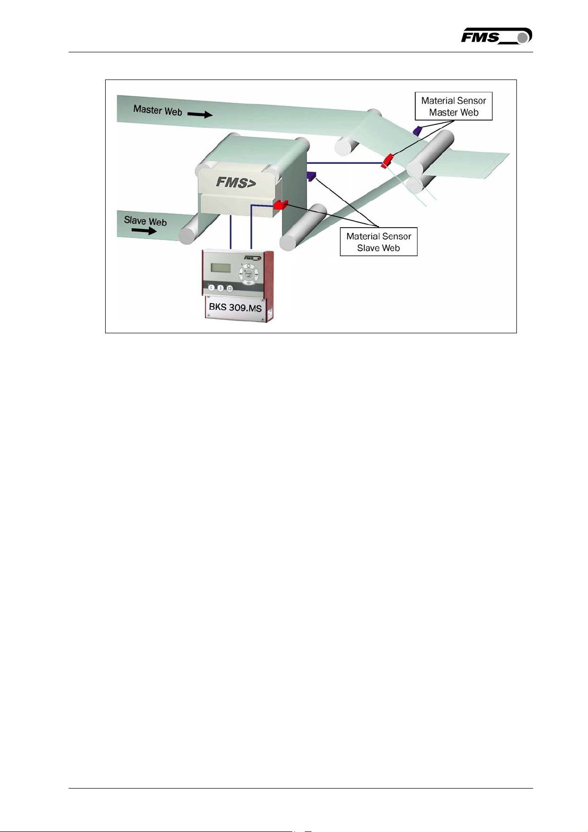
2.2 Web Guide Controller with Master-Slave Functionality
For the lamination of two webs Chase & Follow Control Systems are often used. This
control system enables the exact positioning of two webs one above the other. The
BKS309.MS web guide controller with Master-Slave functionality measures the
position of a first web (Master) and guide a second web (Slave) so that both webs
exactly match each other. Chase & Follow guiding requires at least one steering
frame (or actuator) and two material sensors.
The material sensors are mounted on the same side of the corresponding webs.
Either both on the left, or both on the right hand side.
14.08.2018 5
Page 6
Operating Manual BKS309.MS
Fig. 2: System with Master-Slave Functionality (BKS309.MS) K309003e
2.3 Steering Frame or Actuator
The steering frame consists of a fixed lower and a moveable upper frame that
supports the rollers. The upper frame is activated by a stepper motor. The rollers are
manufactured and balanced according to customer specification. End positions are
controlled via a linear potentiometer. A location rail for easy sensor attachment is
integrated to the steering frame. For rewind und unwind stands a stepper motor
based drive acts as actuator.
2.4 Electronic Control Unit
The micro-processor based electronic control unit handles all calculations and
communications. Three buttons and a five key wind-rose serve as the man-machine
interface. Parameter setting can be performed via the front panel keys or via a web
interface. The BKS309 controller series works in combination with FMS steering
frames of the series webMASTER BKS020, BKS040, webDIRECTOR BKS041/42,
and actuators of the winderGLIDE BKS.D.3 and winderGLIDE BKS.D.6 series.
2.5 Sensors
Optical sensors (AZS01/04), ultrasonic sensors (US01/4B) and a digital line sensor
(DLS) are available from FMS. These sensors provide a signal of 0...10V. With them,
edge, center and line guiding applications can be covered.
14.08.2018 6
Page 7
Operating Manual BKS309.MS
3 Quick Installation Guide
The installation and set-up instructions in this operation manual refer to the
BKS309.MS controller with Master-Slave functionality.
3.1 Preparations for Set-up
• Read the Operation Manual of your web guide or actuator system.
• Check your system requirements such as:
− Operation with steering frame or with actuator
− Unit system (metric, imperial)
− Relay or digital input requirements of your set-up
• Draw the wiring diagram for your configuration (ref. to chapters 5.1 to 5.6)
• If required, determine special parameters (ref. to 8 “Parameter Setting over the
Front Panel”)
3.2 Installation Procedure
1. Mount and ajust your material sensors to the Slave Web (steering frame) and
Master Web (ref. to chapter 4.3)
2. Mount the steering frame or actator to the machine
3. Wire the sensors to the electronic unit (ref. to chapter 5)
4. Wire the steering frame to the electronic unit (ref. to chapters 5.1 to 5.6)
5. If using an external web guide controller, mount the electronics on a place where it
can be easily reached by the operator
6. Make sure the power supply voltage is in the range 18 to 30V DC (Vnom= 24V)
7. Power your system on and check if the electronics starts up (LCD turn on)
8. Install your webs in the machine and align the edge sensors to the material (ref.
3.3 “Adjustment of the Sensors”).
If necessary, continue with the configuration of your system (ref. to chapter 6)
9.
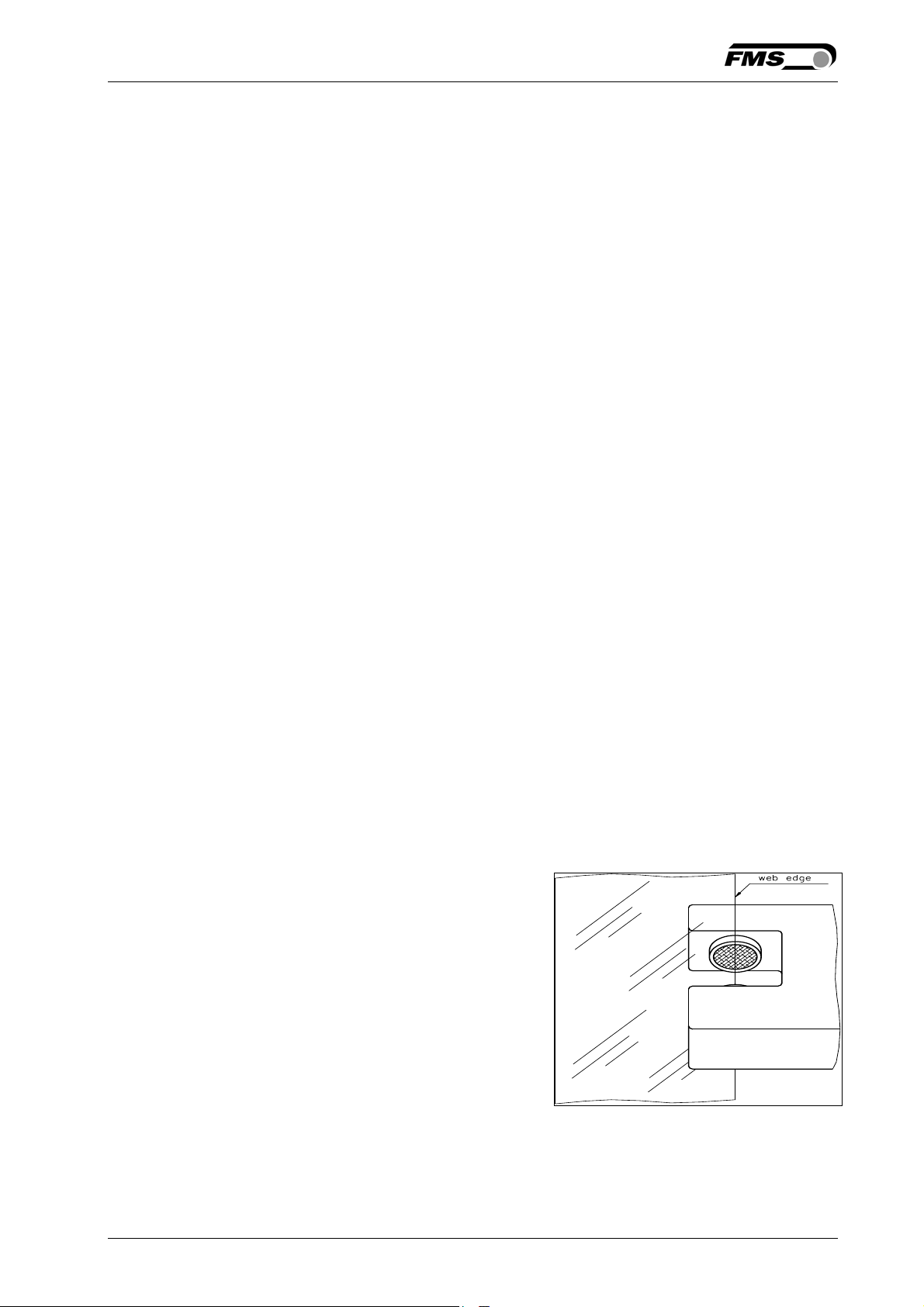
3.3 Adjustment of the Sensors
Align sensor axis to the web edge: Loosen the
fixing nut on the bracket and adjust the
sensor. Fix the sensor in the new position.
The sensor will be positioned properly if the
web edge goes through the sensor axis
(center of active window (ref. to Fig. 3).
Fig 3: Alignment of the sensor axis to
the web edge K100004e
14.08.2018 7
Page 8
Operating Manual BKS309.MS
4 Installation
Caution
Proper function of the FMS web guides and actuators is only guaranteed with the
recommended application of the components. Other arrangements, can cause
heavy malfunctions. Therefore, the installation instructions on the following pages
must strictly be followed.
Caution
Local installation regulations are to preserve safety of electric equipment. They are
not taken into consideration by this operating manual. However, they have to be
followed strictly.
4.1 Mounting the Steering Frame
The mounting orientation of the steering frame (indicated by an arrow), must
correspond with the web running direction. The lower frame is mounted with four M8
screws to the machine frame. The machine must be prepared to accept the M8
mounting screws.
4.2 Mounting the Actuator to your Unwind or Rewind Station
The static part of the winderGLIDE actuator must be mounted to the machine frame
e.g. to the spherical rod end on the gearbox. The moving rod end is mounted to the
winding stand. For other assembly forms consult the operation manual of the
BKS.D.3 respectively BKS.D.6. The BKS.D.3 / D.6 are designed for horizontal
mounting positions. The machine frame must be prepared to accept the mounting
devices of the winderGLIDE.
4.3 Mounting the Sensors
The sensors will be mounted with brackets to the rail of the steering frame or to the
sensor arrangement of the Master Web (refer to operation manual AZS01, US01 or
DLS). The sensors have to be installed after the steering frame if seen in running
direction of the web. They have to be mounted so that the narrow side is closer to the
steering frame (see Fig. 4).
Caution
The material sensors for the Master Web and for the Slave Web must both be
mounted on the same side (either left or right side).
14.08.2018 8
Page 9
Operating Manual BKS309.MS
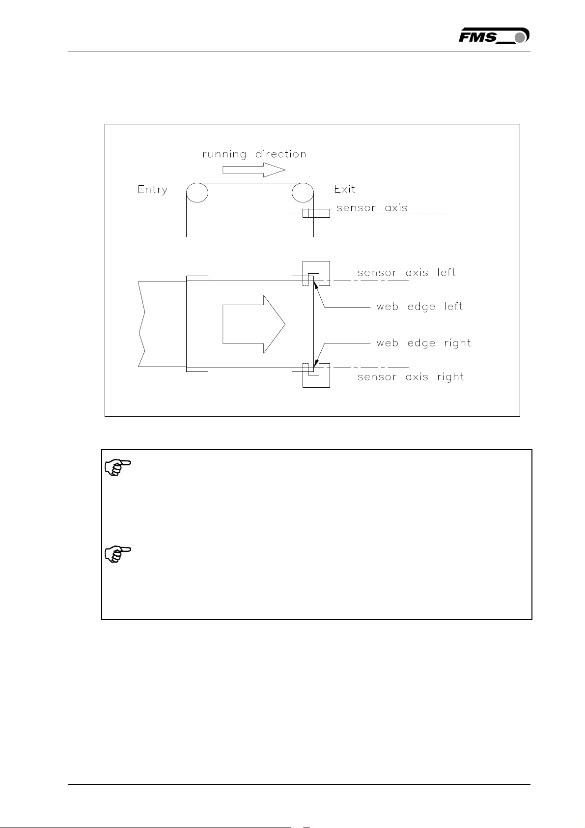
Definition of Left and Right:
Left and right are always seen in direction of the running web (see Fig. 4).
Fig. 4: Position of the sensors according to the web K400005e
Note
Make sure that the sensors are connected properly to the electronic unit by means
of the delivered cables. For left / right orientation please refer to Fig. 4. If the
connections are crossed over, malfunction can be the result.
Note
For optimum control results, the sensors have to be placed next to the exit roller of
the steering frame. If the sensors are placed far from the steering frame, control
dynamics will deteriorate.
4.4 Mounting the Electronic Control Unit
The BKS309.MS series is available in four different housing options:
1. Rail mount housing (electrical connections via screw terminals)
2. Rail mount housing (electrical connections via connectors)
3. Wall mount housing
4. Panel mount housing
The mechanical dimensions can be seen in chapter 10 “Mechanical Dimensions”.
14.08.2018 9
Page 10
Operating Manual BKS309.MS
5 Wiring Diagrams
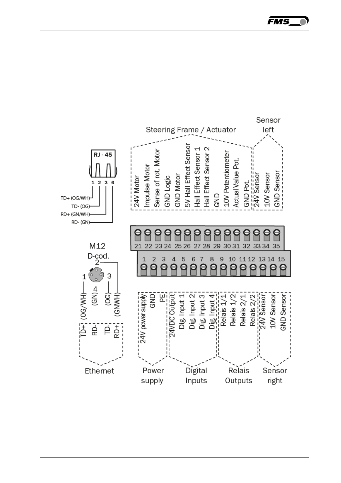
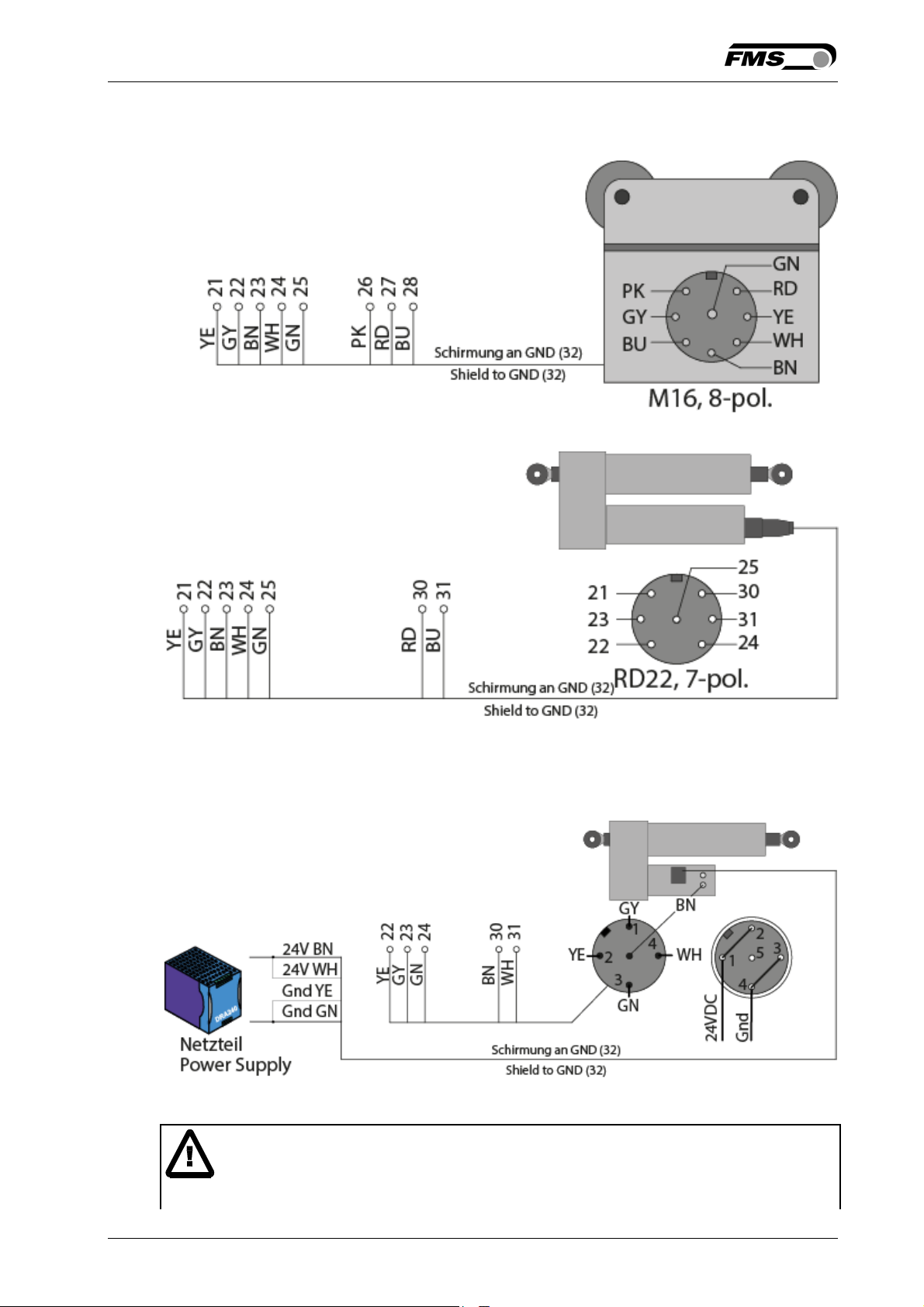
Use the original FMS cables to connect the steering frame respectively the actuator
to the BKS309.MS controller. The connector end of the cable is connected either to a
steering frame or a BKS.D.3 / D.6 actuator. The open ends of the cables must be
wired to the cable terminals in the controller according to the wiring diagrams below
(ref. also to Fig. 5 or Fig. 7)
5.1 Wiring a Steering Frame with BKS309.R / .S or .W Controller
Sensor right = Master sensor
Sensor left = Slave sensor
Please note that both sensors must be installed either on the right or the left side of the
webs.
Fig. 5: Connection terminals BKS309.MSBKS309.ai
14.08.2018 10
Page 11
Operating Manual BKS309.MS
5.2 Connecting webMASTERs BKS015 or BKS020
5.3 Connecting a winderGLIDE BKS.D.3 or a webMASTER BKS030
The illustration show a BKS.D.3 as sample. A BKS030 is equally wired.
5.4 Connecting a winderGLIDE BKS.D.6
Caution
Bad earth connections may cause electric shocks to persons, malfunction of the
14.08.2018 11
Page 12

Operating Manual BKS309.MS
total system or damage of the control unit! It is vital to ensure that the earth
connection is properly done.
14.08.2018 12
Page 13

Operating Manual BKS309.MS
6 Configuring the System
After having mounted and wired the web guiding equipment on the machine, the
system can now be configured to the specific requirements of the application.
6.1 Power up the BKS 309.MS
1. Make sure the power supply voltage is in the range 18…30 VDC (Vnom= 24V)
2. Check, if the web is in the detection range of the sensors.
3. Switch-on your power supply
4. The web guide controller starts-up in Manual Operating Mode.
5. A web guiding system using BKS309.MS is pre-set to control a chase & follow
application with the master web being connected to the left sensor input (see
wiring diagrams Fig. 5 to 7). If required by the application the asignment of the
master web sensor can be changed by the parameter [MastrInp] (ref. to 8.2
“Setting of Operation Parameters”, Fig 15)
6. If required re-configure the programmable relay outputs (see chapter 6.2)
7. If required re-configure the digital inputs (see chapter 6.3)
14.08.2018 13
Page 14

Operating Manual BKS309.MS
6.2 Relays Outputs
The BKS309 controller provides 2 programmable relay outputs. The outputs are
software controlled. Electrically they are potential-free. Each relay output can be
configured individually and can perform an assign special function. The outputs are
configured in the Parameter Setting Mode. Following functions can be assigned to
each output:
• Indicate centre position of web edge
• Indicated if web edge is detected
• Indicate if web edge is detected and Automatic Mode on
• Indicate if no web edge is detected and Automatic Mode on
• Indicate if Automatic Mode was chosen
• Indicate if steering frame or actuator is centred
For more details about the functions refer to chapter 7.4 “Description Operation
Parameter
Hardware access via screw terminals (see Fig. 3)
”.
Signal Name Terminal #
Relay 1/1 9
Relay 1/2 10
Relay 2/1 11
Relay 2/2 12
6.3 Digital Inputs
The BKS309 controller provides 4 digital inputs for special functions.
The digital inputs are edge or level triggered. An impulse of 100ms or longer
activates the event. Each digital input can be configured individually and can perform
an assign special function. The digital inputs are configured in the Parameter Setting
Mode. Following function can be assign to each digital input:
• Toggle between Manual and Automatic mode (edge triggered)
• Toggle between Manual and Automatic mode (level triggered)
• Go to centre position
• Decrease reference value in 0.1mm steps in (deactivated for BKS309.MS)
• Move actuator in 0.1mm steps to the left
• Increase reference value in 0.1mm steps (deactivated for BKS309.MS)
• Move actuator in 0.1mm steps to the right
• Lock steering device (steering frame or actuator)
• Reset reference value (deactivated for BKS309.MS)
For more details about the functions refer to chapter 8.4 “Description Operation
Parameter
”.
14.08.2018 14
Page 15
Operating Manual BKS309.MS
Caution
If the function “Toggle between Manual and Automatic mode” is controlled via the
digital inputs, the corresponding key on the operation panel will be
deactivated.
Hardware access via screw terminals (see Fig. 9)
Signal Name Terminal #
Dig.In 1 5
Dig.In 2 6
Dig.In 3 7
Dig.In 4 8
.
6.4 Differences between Standard and Master-Slave Electronics
Due to its use in the special field of chase & follow applications the BKS309.MS
Master-Slave unit has a slightly different parameter set if compared with the
standard web guide controller BKS309. Several functions aren’t any more available
with the BKS309.MS. Parameters connect to these functions are displayed and can
be modified without having any influence in the application. Following function are
not available in the BKS309.MS unit:
• Reset of the frame reference position via digital inputs or the keys and on
the operation panel.
• Setting the Reference Value over the parameter [Ref Pos]
• Determination of the Reference Position is deactivated and thus the parameter
[Ref Mod] has no impact. The Reference Position is always defined by the Master
Web Position.
• A change of the Reference Position in automatic operation via the digital inputs or
via the web interface is not possible.
14.08.2018 15
Page 16
Operating Manual BKS309.MS
7 Operation
7.1 Operation Panel
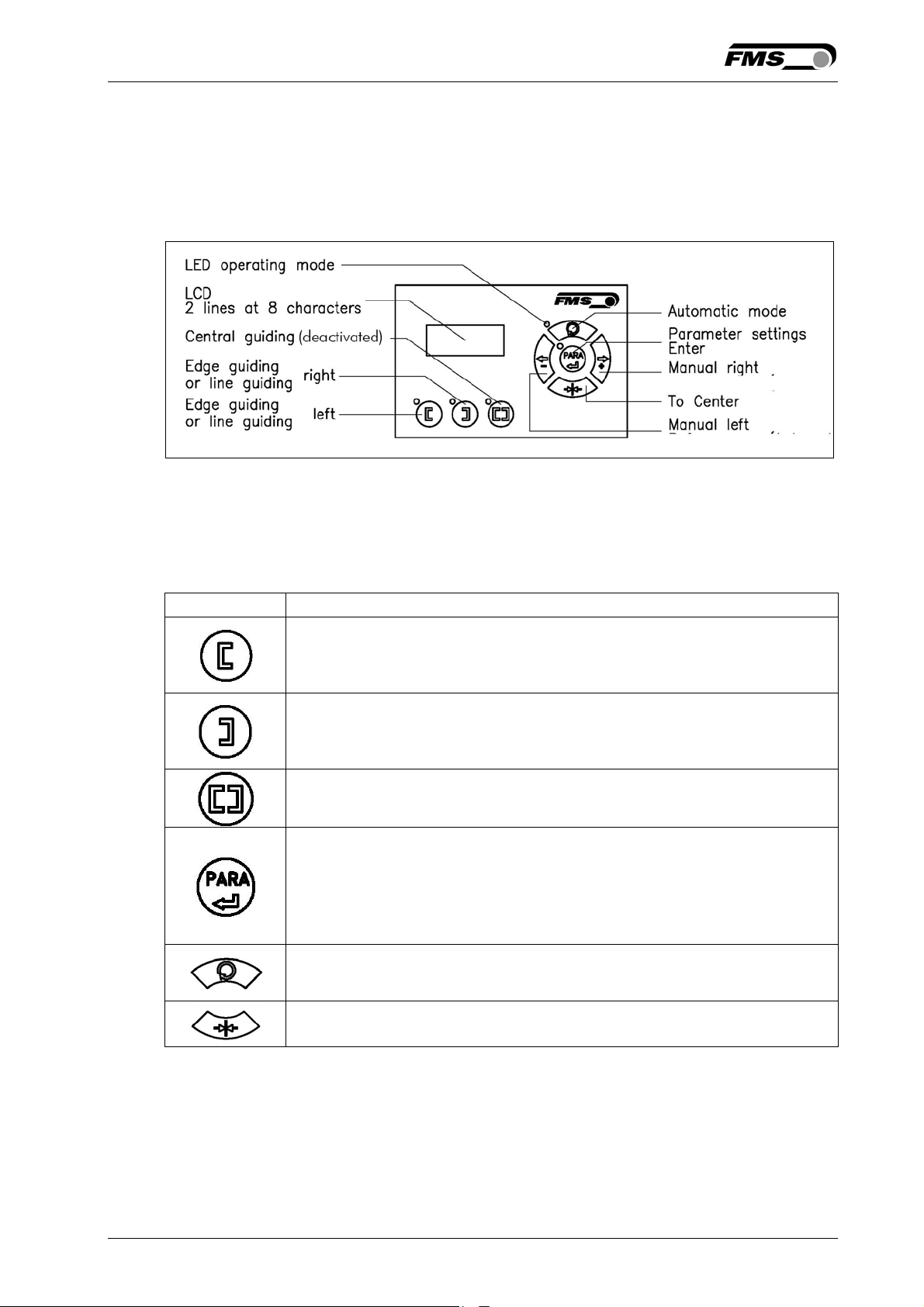
Fig. 11: View of the Operation Panel K309039e
7.2 Operating the Web Guiding System via the Front Panel
Key Key function during operation
The sensor is mounted on the left side of the frame and controls the
material on the left edge or on the line, if a line sensor is used. One sensor
is necessary.
The sensor is mounted on the right side of the frame and controls the
material on right edge or on the line, if a line sensor is used. One sensor is
necessary.
Centre guiding mode is deactivated for BKS309.MS
To enter the Parameter Setting Mode, hold the key for longer then 3
sec. The LED will light and the first parameter will appear on the
LCD display indicating that you entered the mode. A second press
on the PARA key will cause the parameter to flash. Now it can be
changed (ref. to 6 “Parameter Setting over the Front Panel”)
Automatic, Manual. With this key you can select between automatic
and manual mode. The LED indicates the automatic mode.
The LED indicates the left edge guiding mode.
The LED indicates the right edge guiding mode.
Drive to center position. The frame moves to the center
Position. Function is only available in manual mode.
14.08.2018 16
Page 17
Operating Manual BKS309.MS
In manual mode the frame will move to the left in 0.1mm steps by
pressing the button once. By pressing the button longer than 1 sec.
it will continuously move the frame to the left.
In automatic mode: Adjust Reference Position (left) is deactivated
for BKS309.MS.
In Setup-Position and independent if the device is in manual or automatic
mode, pressing the button increases continuously the parameter value.
In manual mode the frame will move to the right in 0.1mm steps by
pressing the button once. By pressing the button longer than 1 sec. it
will continuously move the frame to the right.
In automatic mode: Adjust Reference Position (right) is deactivated
for BKS309.MS
In Setup-Position and independent if the device is in manual or automatic
mode, pressing the button increases continuously the parameter value.
Note
If DLS (digital line sensors) are used, it may happen that the web guide controller
blocks the steering frame. This protective function is activated when the line is
interrupted and impossible to detect the line anymore. The LED above the
.key will start blinking and indicate to operator that the line quality is bad.
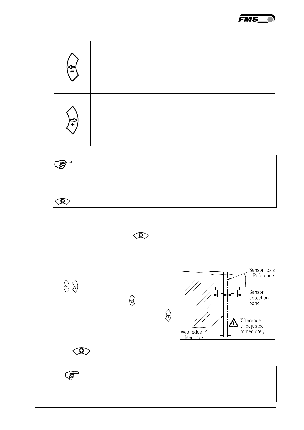
7.3 Automatic Operation
• Start automatic mode with key or digital input. Reference position is taken
from the middle of the sensor detection band (Fig. 12). Using center guide,
reference position is in the middle between the 2 sensor axis. The controller starts
to guide the web to reference position and to hold this guide point.
• The reference position can be adjusted
during automatic operation by using the
• keys or using digital inputs (step
width 0.1 mm). Using the key, the web
moves out of the sensor; using the
key, the web moves in Using center guide,
this description refers to the right sensor.
• Terminate the automatic mode by using
the key again.
Fig. 12:
100005e
Position at automatic start K
Note
If the web leaves the sensor detection band, control is no longer effective. Hold
the web edge strictly inside the sensor detection band.
14.08.2018 17
Page 18
Operating Manual BKS309.MS
Note
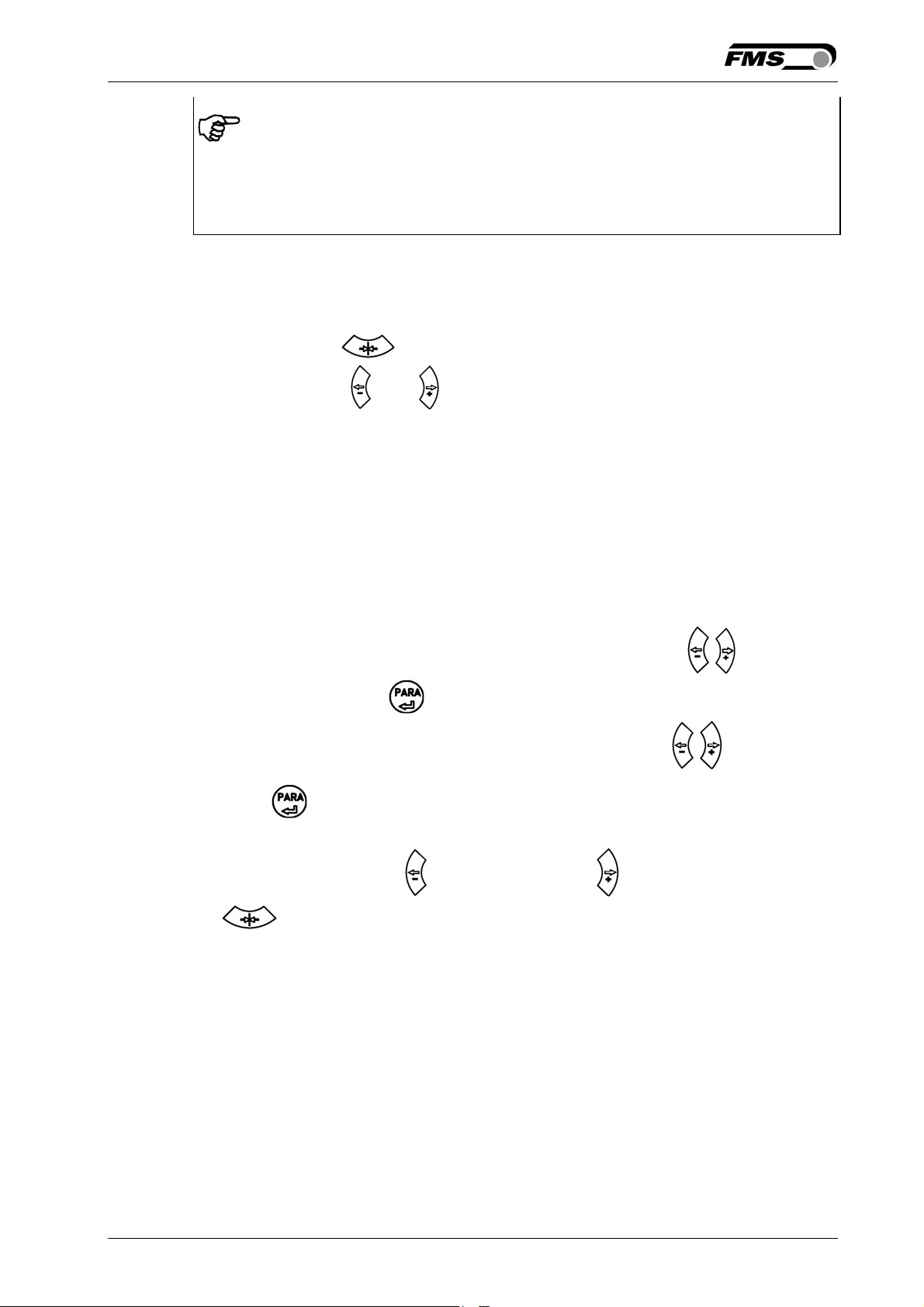
If web is not running, it can’t be guided properly to the reference position! The steering
frame moves in the limit-of-travel position and may damage the web. Start automatic
mode only when web is slowly running.
7.4 Manual Operation
In manual mode, possibilities as follows are available:
• Center position : The steering frame will return to center position.
• Frame position and : The steering frame can be adjusted in 0.1mm
steps. If key is held, steering frame is moving continuously. These functions
can also be carried out via the digital inputs (see 4.7 “Digital Inputs”).
7.5 Saving the Travel Limits
There are two possibilities to alter the limits for the Home Position, Middle Position
and Maximum Positions of the actuator. Either you modify the parameters [Home
Pos], [Mid Pos] and [Max Pos] in the parameter changing mode or you drive manually
to the desired position and save it. The procedure for is then as follows:
1. Enable the change of the travel limits by pressing the two keys at the same
time. The LED above the key will light.
2. Travel with the actuator to the desired position with the keys .
3. Press the key. The LED above the key starts to flash and expects the
definition of the setting.
4. The definition is done with for the Home Position, for the Maximal Position
and
5. On the displayed following comments will report completion.
Display first line: [Save Pos]
Display second line: [Done] or [Invalid]
In the case of [Invalid] the display flashes. The position couldn’t be found e.g.
because the “home” or “maximum” position was set over the middle position.
for the Middle Position
14.08.2018 18
Page 19
Operating Manual BKS309.MS
8 Parameter Setting over the Front Panel
8.1 Basic Instructions for Parameter Setting
The web guide controller has three operator modes:
• Operation mode
• Parameter Setting mode (parameter selection)
• Change mode (set or change chosen parameters)
The parameter setting can be performed via the keys on the front panel or via a web
browser. When using the front panel, the user can toggle between these modes by
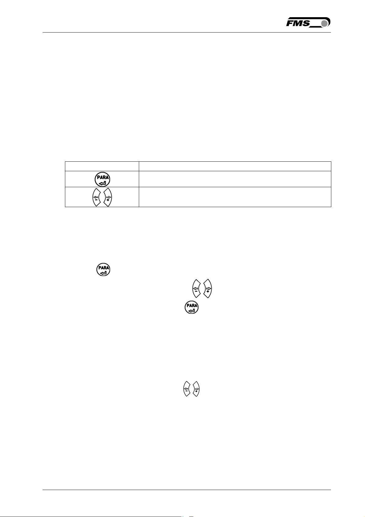
pressing a key or a combination of keys. The keys have the following functions:
Key Key function during parameter setting
Enter
Change the selections or increase / decrease the values
8.2 Setting of Operation Parameters
To enter the Parameter Setting Mode the web guide controller must be in the Manual
Mode. In the Automatic Mode only the reference value can be changed.
Press the key for longer then 3 sec. The LED will light and the first parameter
will appear on the LCD display. With the .keys the parameter list can be
scrolled up and down. By pressing the key again you will enter the parameter
setting mode. The select parameter on the display flashes indicating that it can be
changed.
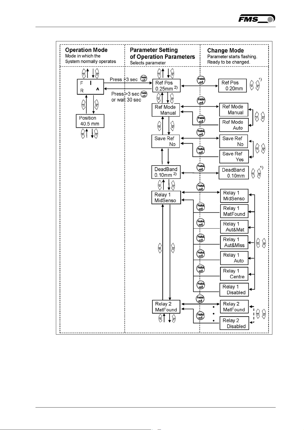
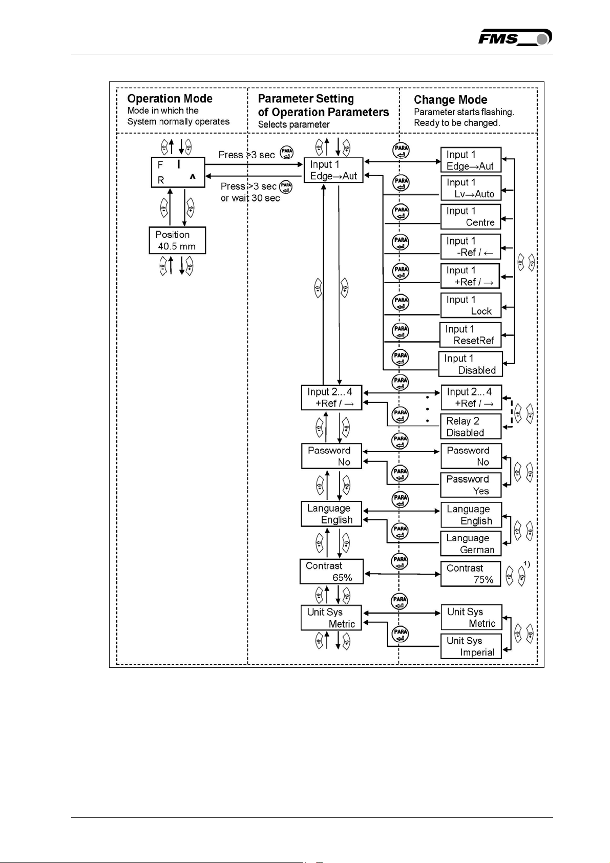
The following state diagrams will help you to navigate through the Parameter Setting
menu.
Notes for the following state diagrams:
1)
Permanent pressing of the keys expedites the changing speed.
2)
The display shows the unit of measure that was previously selected.
3)
Parameter only used in winderGLIDE (actuator) applications
4)
This parameter change requires a restart of the web guide controller.
14.08.2018 19
Page 20
Operating Manual BKS309.MS
Fig. 13: State Diagram Operation Parameters (1) K309009e
14.08.2018 20
Page 21
Operating Manual BKS309.MS
Fig. 14: State Diagram Operation Parameters (2) K309010e
14.08.2018 21
Page 22
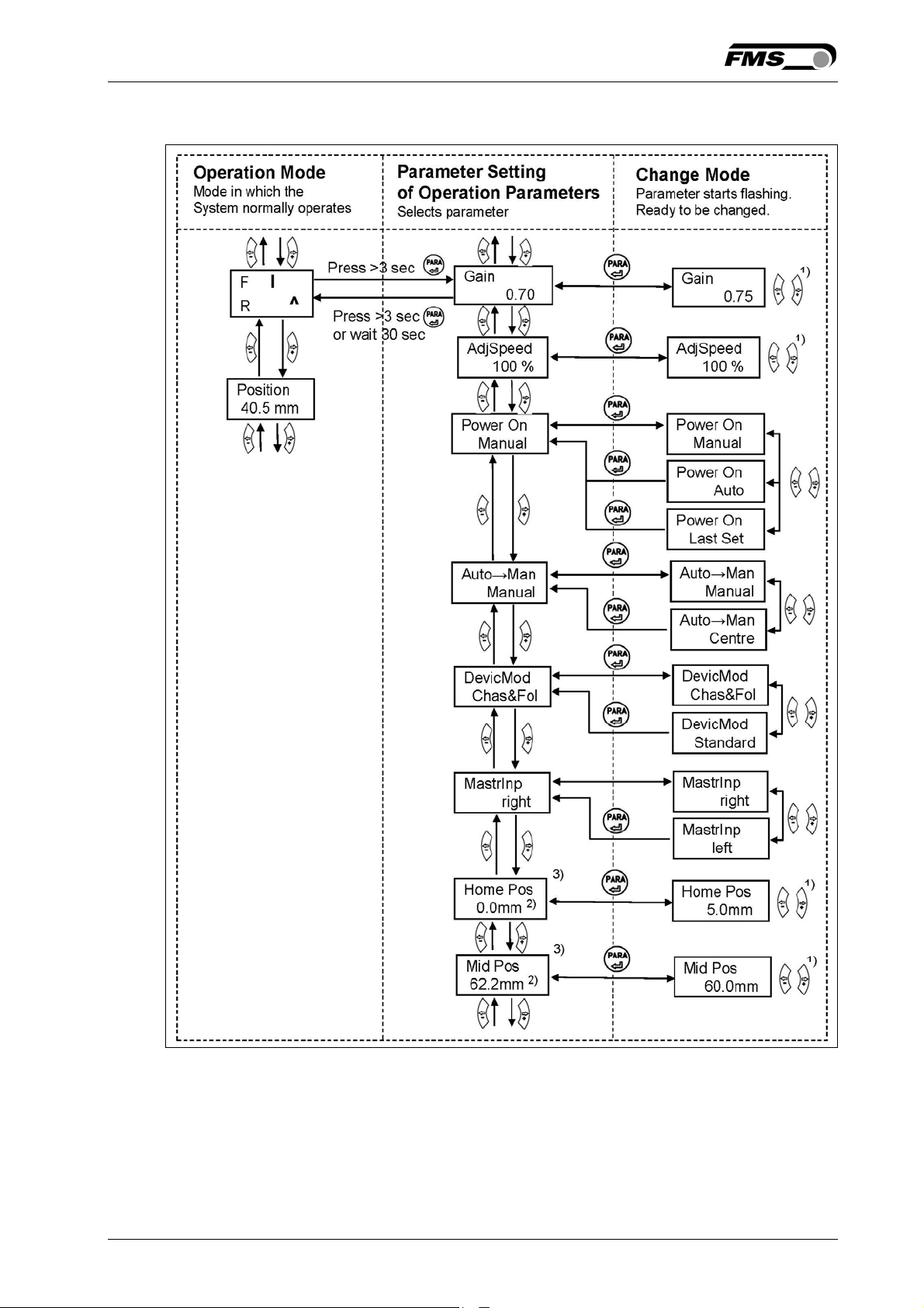
Operating Manual BKS309.MS
Fig. 15: State Diagram Operation Parameters (3) K309011e_MS
14.08.2018 22
Page 23
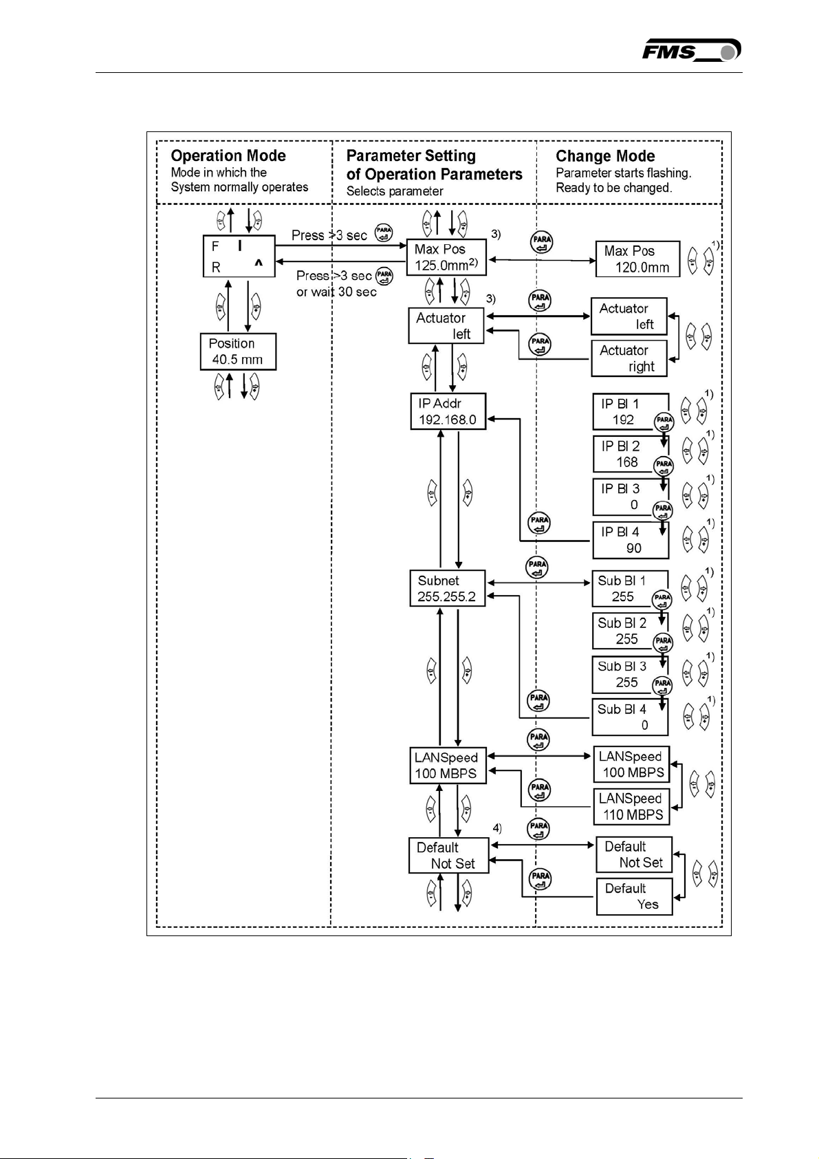
Operating Manual BKS309.MS
Fig. 16: State Diagram Operation Parameters (4) K309014e_MS
14.08.2018 23
Page 24
Operating Manual BKS309.MS
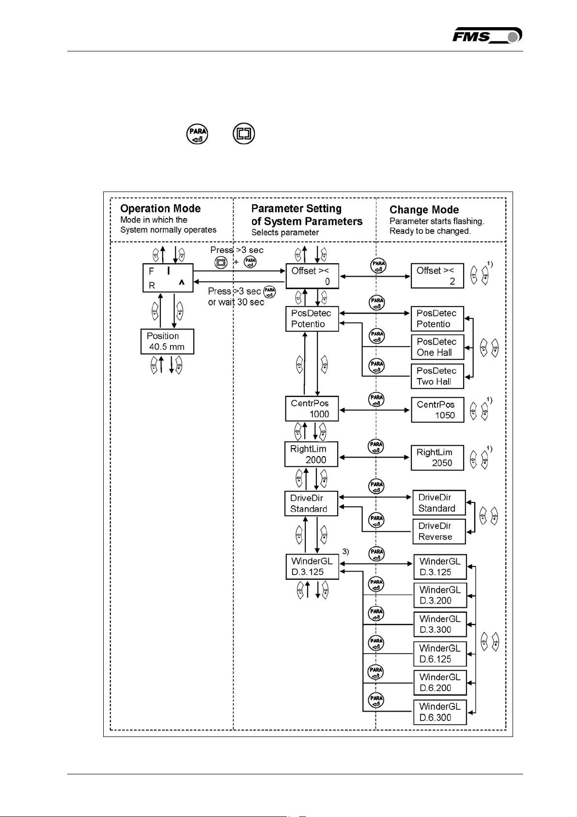
8.3 Setting of System Parameters
To enter the Parameter Setting Mode the web guide controller must be in the Manual
Mode. Press the and key together for longer than 3 sec to enter the System
Parameter List. The LED will light and the first parameter will appear on the LCD
display. Proceed like in chapter 8.2 for changing parameters.
Fig. 17: State Diagram System Parameters K309018e
14.08.2018 24
Page 25

Operating Manual BKS309.MS
8.4 List of Operation Parameters
Parameter LCD Unit Min Max Selection Default
Adjust Reference
Position
Set Reference
Mode
Save the
Reference Position
Ref Pos
mm -5.00 +5.00 - 0.00
Ref Mode - - -
SaveRef - - -
Manual
Auto
No
Yes
Manual
No
Dead band DeadBand mm 0.0 2.0 - 0.1
Relay 1 or Relay 2
setting
Relay 1
Relay 2
- - -
MidSenso
MatFound
Auto&Mat
R1=
MidSenso
Aut&Miss
Auto
Centre
R2=
MatFound
Disabled
Digital Input 1, 2,
3 or 4 Modes
Input 1
Input 2
Input 3
Input 4
- - -
Edge→Aut
Lv→Auto
Centre
- Ref/←
+Ref/→
Centre
Lock
ResetRef
I1=
Edge→Aut
I2=Center
I3=
-Ref/←
I4=
+Ref/→
Disabled
DLS Sensor DLS - - - none
none
left
right
Language Language - - -
English
German
Password Password - - -
No
English
No
Yes
LCD-Contrast Contrast % 1 100
Unit System Unit Sys - - -
- 65
Metric
Metric
Imperial
Gain Setting Gain - 0.02 2.00 - 0.2
Adjust Correction
AdjSpeed % 1 100 - 100
Speed
Power Modes Power ON - - -
Manual
Manual
Auto
Last Set
14.08.2018 25
Page 26

Operating Manual BKS309.MS
Behaviour when
Auto→Man - - leaving Automatic
Mode
8.5 List of System Parameters
Parameter LCD Unit Min Max Selection Default
Manual
Centre
Manual
Device Mode DevicMod - - -
Chas&Fol
Chas&Fol
Standard
Master Input MastrInp - - - right
right
left
Home Position 3)
Middle Position3)
Maximal Position3)
Actuator Actuator - - -
Home Pos mm 0.0 300.0 -
Mid Pos mm 0.0 300.0 -
Max Pos mm 0.0 300.0 -
Left
0.0 3)
62.5 5)
125.0 5)
Left
Right
IP Address IP Addr - 0 125 -
192.168.0
.090
Subnet Subnet 0 255 -
255.255.2
55.0
LAN Speed LANSpeed MBPS - -
10
100
Factory Settings 4)
Default - - -
Not set
Not Set
Yes
3)
Parameter only used in winderGLIDE (actuator) applications
4)
This parameter change requires a restart of the web guide controller.
5)
The default value is dependent on the actuator used.
14.08.2018 26
Page 27
Operating Manual BKS309.MS
8.6 Description Operation Parameter
Adjust Reference Position [Ref Pos]
Purpose: The reference position can be adjusted using this parameter.
Range: -5.00 to +5.00 Default: 0.00
Increment: 0.01 Unit: [mm]
Set Reference Mode [Ref Mode]
Purpose: This parameter determinates how the reference position is defined.
This can either be the position that is defined with parameter [Ref
Pos] or the actual material position within the sensor when the
controller is switched to automatic operation.
Two settings are possible:
Setting: [Manual]
Purpose: If [Manual] is chosen, the Reference Position is taken from the
parameter [RefPos].
Setting: Automatic [Auto]
Purpose: If [Auto] behaviour is chosen, the Reference Position is determinate
by taking the actual material position within the sensor when the
controller is switched to automatic operation.
Save the Reference Position [SaveRef]
Purpose: The parameter saves the last Reference Position change. It sets after
re-booting the Reference Position to the last used value or to 0 (zero).
Two settings are possible:
Setting: [No]
Purpose: If [No] behaviour is chosen, the Reference Position is set to 0 after
rebooting (default setting).
Setting: [Yes]
Purpose: If [Yes] behaviour is chosen, after rebooting the Reference Position is
set to the last used value.
14.08.2018 27
Page 28
Operating Manual BKS309.MS
Dead band [DeadBand]
Purpose: This parameter defines the dead band tolerance. Dead band is a free
programmable range, in which the web may move freely without the
steering readjusting the frame. Keep in mind that: A [DeadBand] of
e.g. 0.3mm“ results in a tolerance band of ±0.3mm.
If the deviation is higher than the tolerance, the web will be readjusted into
the range of the dead band.
Range: 0.0 to 2.0 Default: 0.1
Increment: 0.1 Unit: [mm]
Relay 1 or Relay 2 setting [Relay 1 or 2] (two Parameters one for each relay)
Purpose: This parameter determines the relay behaviour.
The user can choose between seven settings.
Setting: Middle Position [MidSenso]
Purpose: If [MidSenso] is chosen then the relay goes on when the material
edge is at the sensor’s middle position.
(Default setting for Relay 1)
Setting: Material Found [MatFound]
Purpose: If [MatFound] is chosen then the relay goes on when material edge
is detected. (Default setting for Relay 2)
Setting: Automatic Mode and Material Found [Auto&Mat]
Purpose: If [Auto&Mat] is chosen then the relay goes on when material edge
is detected and the controller is in Automatic Operation.
Setting: Automatic Mode and Material Missing [Aut&Miss]
Purpose: If [Aut&Miss] is chosen then the relay goes on when no material
edge is detected and the controller is in Automatic Operation.
Setting: Automatic Operation [Auto]
Purpose: If [Auto] is chosen then the relay goes on when the controller is in
Automatic Operation.
Setting: [Centre]
Purpose: If [Centre] is chosen then the relay goes on as soon as the motor
drive stands still after a centre run.
Setting: [Disabled]
Purpose: If [Disabled] is chosen then the relay function is disabled. The relay
will never go on.
14.08.2018 28
Page 29
Operating Manual BKS309.MS
Digital Input 1, 2, 3 or 4 Modes [Input 1…4]
These are actually fore parameters one for each digital input
Purpose: This parameter determines the functions of the digital inputs.
The user can choose between seven settings.
Setting: Edge Triggered Automatic Mode [Edge→Aut]
Purpose: The controller switches either to automatic or manual operation
depending in which mode the controller currently is. The switching is
taking place when a rising edge is detected on the digital input.
(Default setting for dig. input 1)
Setting: Level Controlled Automatic Mode [Lv→Auto]
Purpose: The controller switches either to automatic or manual operation
depending on the voltage level at the digital input. If the voltage is
high then the controller switches to Automatic otherwise to Manual
Operation.
Setting: Drive to Center Position [Centre]
Purpose: If [Centre] is chosen then the motor drive moves to the centre
position. The event is edge triggered. (Default setting for dig. input 2)
Setting: Move Frame to the Left [-Ref/←]
Purpose: In manual operation the motor drive moves to the left respectively to
the retracted position (default setting for dig. input 3).
Setting: Move Frame to the Right [+Ref/→]
Purpose: In manual operation the motor drive moves to the right respectively to
the extended position (default setting for dig. input 4).
14.08.2018 29
Page 30
Operating Manual BKS309.MS
Setting: Lock Guide [Lock]
Purpose: The motor drive is immediately locked when this parameter is chosen
and the digital input voltage is high.
Dig. Input Lock, Operation State Automatic and Parameter
[Auto→Man] work in a combinative manner. Their interdependency is
described in the following table:
Dig. In.
Lock
Op. State
Automatic
Parameter
Auto→Man
Function
0 inactive Centre Move to middle position
0 active irrelevant Automatic operation
1 inactive Manual Stop at actual position
1 inactive Centre Move to middle position
1 active irrelevant Stop at actual position
Setting: Reset of Reference Value [ResetRef]
Purpose: This function resets the reference value to 0, if a positive signal edge
is applied to the digital input.
Setting: Disabled
Purpose: With [Disabled] parameter the digital input is disabled.
DLS
Purpose: If you use a DLS2 sensor, you have to set the correct installation
direction. You can only connect one DLS2 sensor.
The user can choose between three settings.
Setting: [none]
Purpose: There is no DLS2 sensor connected
Setting: [left]
Purpose: The DLS2 sensor is installed on the left-hand side (in direction of the
moving web)
Setting: [right]
Purpose: The DLS2 sensor is installed on the right-hand side (in direction of
the moving web)
14.08.2018 30
Page 31
Operating Manual BKS309.MS
Password
Purpose: The web guide controller can be protected from unauthorised access
by means of password. If Password Yes is chosen, the system will
request the password to change parameters and other setting. The
password itself can’t be changed. It is always 3231
The user can choose between two settings
Language: [No]
Purpose: The Password protection is deactivated (default setting)
Language: [Yes]
Purpose: The Password protection is activated
14.08.2018 31
Page 32
Operating Manual BKS309.MS
Language
Purpose: This parameter determines the displayed language.
The user can choose between two languages.
Language: [English]
Purpose: If [English] is chosen, the display shows all texts in English. The web browser
is always in English.
Language: [German]
Purpose: If [German] is chosen, the display shows all texts in German.
LCD-Contrast [Contrast]
Purpose: The parameter [Contrast] changes the contrast of the LCD to achieve
optimal readability.
Range: 1 to 100 Default: 65
Increment: 1 Unit: [%]
Unit System [Unit Sys]
Purpose: This parameter determines the unit system used.
The user can choose between two settings.
Setting: [Metric]
Purpose: If [Metric] is chosen, the controller displays all data in metric units.
Setting: [Imperial]
Purpose: If [Imperial] is chosen, the controller shows all data in imperial
units.
Gain Setting [Gain]
Purpose: This parameter defines the gain of the feed back value.
Range: 0.02 to 2.00 Default: 0.20
Increment: 0.01 Unit: [ - ]
14.08.2018 32
Page 33
Operating Manual BKS309.MS
Adjust Correction Speed [AdjSpeed]
Purpose: This parameter determines the maximum used speed.
Range: 1 to 100 Default: 100
Increment: 1 Unit: [%]
Power Modes [Power ON]
Purpose: This parameter determines the operation mode after power on.
The user can choose between three behaviours.
Setting: [Manual]
Purpose: The controller goes to Manual Operation Mode after power on.
Setting: Automatic [Auto]
Purpose: The controller goes to Automatic Operation Mode after power on.
Setting: Last Setting Used [Last Set]
Purpose: The controller restores the operation mode that was previously
chosen before power off.
Behaviour when leaving Automatic Mode [Auto→Man]
Purpose: This parameter determines the behaviour of the controller leaving
the automatic mode.
The user can choose between two behaviours.
Setting: [Manual]
Purpose: The controller stops guiding. The motor drive is locked at the
current position (Manual Mode).
Setting: [Centre]
Purpose: The controller stops guiding. Afterwards the motor drive moves to
the centre.
14.08.2018 33
Page 34
Operating Manual BKS309.MS
Device Mode [DevicMod]
Purpose: This parameter determines whether the web controller controls a
standard steering frame or a Chase & Follow application.
The user can choose between the two settings.
Setting: [Chas&Fol]
Purpose: Control of a Chase & Follow application (default setting)
Setting: [Standard]
Purpose: Control of a standard FMS steering frame
.
Master Sensor Input [Mastrinp]
Purpose: This parameter determines in a Chase & Follow application the
sensor input connector for the master web.
The user can choose between two settings.
Setting: [right]
Purpose: The right sensor input is used for the master web (default setting).
Setting: [left]
Purpose: The left sensor input is used for the master web.
Home Position [Home Pos]
Purpose: This parameter determines the position of the actuator spindle in
its retracted position. In Automatic Mode the actuator stops at this
position and moves no further backwards. In Manual Operation
this parameter has no meaning.
Range: 0.0 to 300.0 Default: 0.0
Increment: 0.1 Unit: [mm]
Condition: This parameter appears on the display only if an actuator /
winderGLIDE is connected to the controller.
14.08.2018 34
Page 35
Operating Manual BKS309.MS
Middle Position [Mid Pos]
Purpose: The [Mid Pos] parameter determines the centre position of the
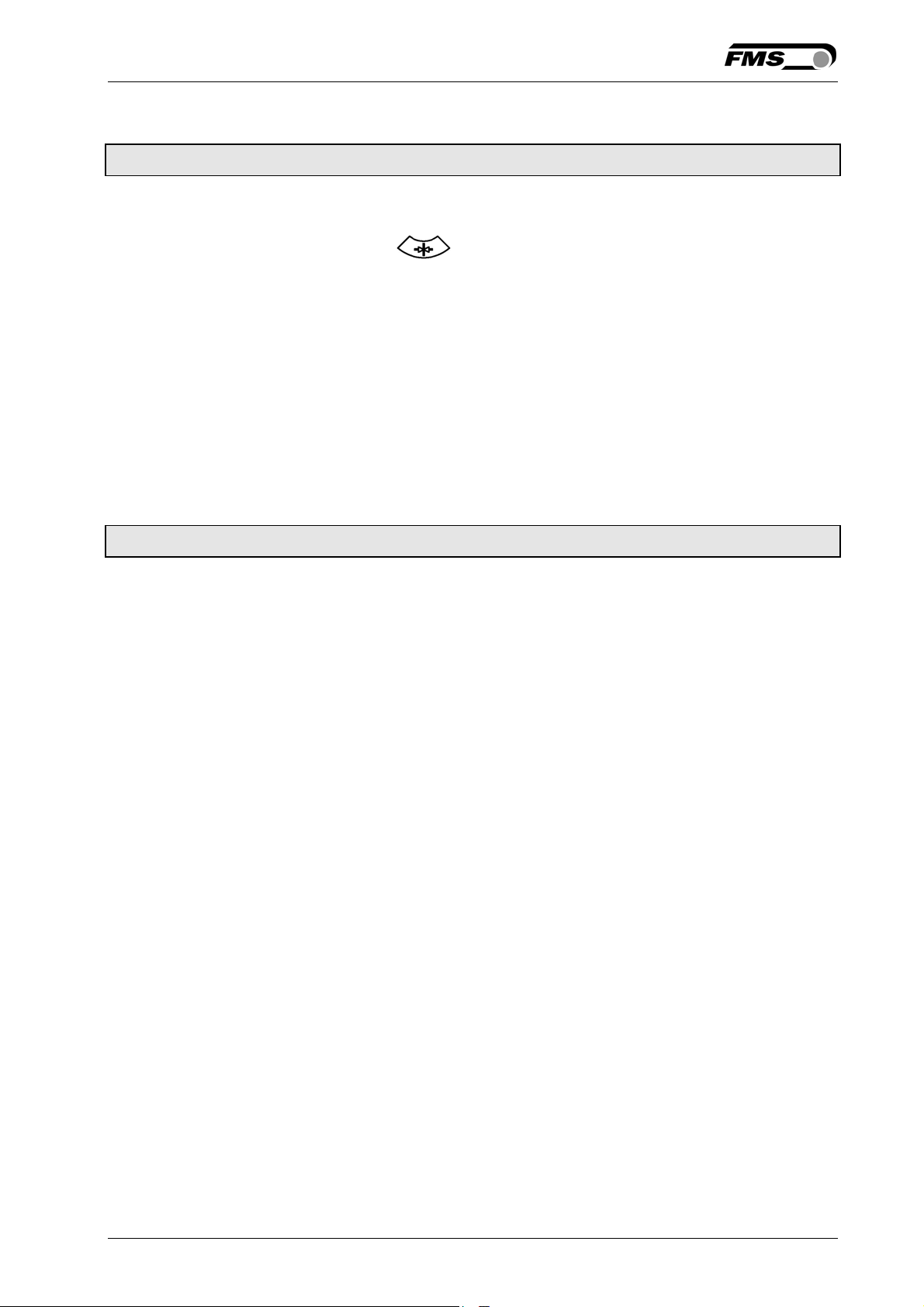
actuator spindle. An actuator stops at this position, if you press the
centre key . In Automatic Operation this parameter has no
meaning.
Range: 0.0 to 300.0 Default: 62.5
5)
Increment: 0.1 Unit: [mm]
5)
The default value is dependent on the used actuator
Condition: This parameter appears on the display only if an actuator /
winderGLIDE is connected to the controller.
Maximal Position [Max Pos]
Purpose: This parameter determines the limit for the extended position. In
Automatic Mode the actuator stops at this position and moves no
further forward. In Manual Operation this parameter has no
meaning.
Range: 0.0 to 300.0 Default: 125.0
Increment: 0.1 Unit: [mm]
5)
The default value is dependent on the used actuator
5)
Condition: This parameter appears on the display only if an actuator /
winderGLIDE is connected to the controller.
14.08.2018 35
Page 36

Operating Manual BKS309.MS
Actuator [Actuator]
Purpose: The parameter [Actuator] determines the control logic of the web
guide controller BKS309.
Condition: This parameter appears on the display only if an actuator /
winderGLIDE is connected to the controller.
The user can choose between two control directions.
Action: [Left]
Purpose: [Left] is the control direction when the actuator is mounted on the
left side of the unwind/rewind station seen in direction of the
running web (see Fig. 2)
Action: [Right]
Purpose: [Right] is the control direction when the actuator is mounted on the
right side of the unwind/rewind station seen in direction of the
running web (see Fig. 2)
[IP Addr]
Purpose: The parameter assigns an IP address to the controller. This
enables the user to communicate via a web browser with the
controller that is imbedded in a network. The IP address must be
entered in 4 separate blocks (IP Bl. 1; IP Bl. 2; IP Bl. 3; and IP Bl. 4)
Range: 0 to 255 Default: 192.168.0.090
Increment: 1 Unit: [ - ]
[Subnet]
Purpose: The parameter assigns the Subnet Mask of the controller in the
Ethernet network. This enables the user to communicate via a web
browser with the controller. The Subnet Mask must be entered in 4
separate blocks (Sub. Bl 1; Sub. Bl 2; Sub. Bl 3; and Sub. Bl 4).
Range: 0 to 255 Default: 255.255.255.0
Increment: 1 Unit: [-]
14.08.2018 36
Page 37
Operating Manual BKS309.MS
[LANSpeed]
Purpose: [LANSpeed] determines the data speed of the web guide controller
to communicate the receiver (Switch, Hub or PC).
The user can choose between two data speeds.
Action: [100 MBPS]
Purpose: [100 MBPS].means 100 M bit per second
Action: [10 MBPS]
Purpose: [10 MBPS].means 10 M bit per second
Factory Settings [Default]
Purpose: This menu point is a command. It resets the parameters to the
factory settings.
The user can choose between two actions.
Action: [Not Set]
Purpose: If [Not Set] is chosen, all parameters stay as set by the user.
Action: [Yes]
Purpose: If [Yes] is chosen, the default parameters are loaded.
Note
The operation parameters [Home Pos], [Mid Pos], [Max Pos], as
well as all system parameters are not reset with the factory
setting command [Default].
14.08.2018 37
Page 38
Operating Manual BKS309.MS
8.7 Setting of System Parameters
Caution
System parameters are factory settings and should not be changed without contacting the
service department of FMS. An unauthorised change can cause malfunctions in the
system or damage in the machine.
To enter the System Parameter Setting Mode hold the two + keys for longer then
3 sec. The LED will light and the first parameter will appear on the LCD display
Offset Centre [Offset><]
Purpose: This parameter adjusts the position of a steering frame exactly to
the centre.
Position Detection [PosDetec]
Purpose: This parameter determines what devices that are used to detect the limit
positions.
The user can choose between three types.
Type: [Potentio]
Purpose: A potentiometer is used to detect the Home position, Middle
Position and Maximum Position. It is automatically set, if an
actuator / winderGLIDE of the type BKS.D.3 is used.
Type: [One Hall]
Purpose: One hall sensor is used to detect the Home position, Middle
Position and Maximum Position.
Type: [Two Hall]
Purpose: Two hall sensors are used to detect the Home position, Middle
Position and Maximum Position.
14.08.2018 38
Page 39
Operating Manual BKS309.MS
Centre Position [CentrPos]
Purpose: The [CentrPos] parameter is only used with the position detection
system based on hall sensors. For all other position detection
system this parameter is not used and hence not displayed. The
parameter determines the centre position of the actuator spindle
in motor steps (measured from the left reference position). The
actuator stops at this position, if you press the centre key .
In Automatic Operation this parameter has no meaning.
Right Limit [RightLim]
Purpose: The [RightLim] parameter is only used with the position detection
system based on hall sensors. For all other position detection
system this parameter is not used and hence not displayed. The
parameter limits the maximum travel to the right side of the
actuator spindle in motor steps (measured from the left reference
position). In the operation or in manual mode this limit will never
be exceeded
Drive Direction [DriveDir]
Purpose: This parameter determines the guiding orientation of the
controller.
This parameter should not be changed without contacting the
service department of FMS.
Setting: [Standard]
Purpose: [Standard] For standard motors and standard frames of FMS
(default setting).
Setting: [Invers]
Purpose: [Invers] The controller sets the drive direction automatically, if
FMS products are use.
14.08.2018 39
Page 40
Operating Manual BKS309.MS
Actuator Type [winderGL]
Purpose: This parameter determines the used actuator type. The product
name of FMS actuators is winderGLIDE.
The user can choose between three types.
Type: [D.3.125] or [D.6.125]
Purpose: If type [D.3.125] or [D.6.125] is chosen, the maximum travel of the
spindle will be 125mm (4.92in). It is the maximum travel position.
Type: [D.3.200] or [D.6.200]
Purpose: If type [D.3.200] or [D.6.200] is chosen, the maximum travel of the
spindle will be 200mm (7.87in). It is the maximum travel position.
Type: [D.3.300] or [D.6.300]
Purpose: If type [D.3.300] or [D.6.300] is chosen, the maximum travel of the
spindle will be 300mm (11.81in). It is the maximum travel position.
8.8 Reset to Default Parameter Set
Factory settings of your BKS309 web guide controller can be re-established either
over the parameter setting menu (see 7.2 “Setting of Operation Parameters”,
parameter [Default]) or by:
Holding the two keys
+ while powering –up the controller.
Note
The operation parameters [Home Pos], [Mid Pos], [Max Pos], as well as all system
parameters are not reset with the factory setting command [Default].
14.08.2018 40
Page 41
Operating Manual BKS309.MS
9 Parameter Setting via a PC
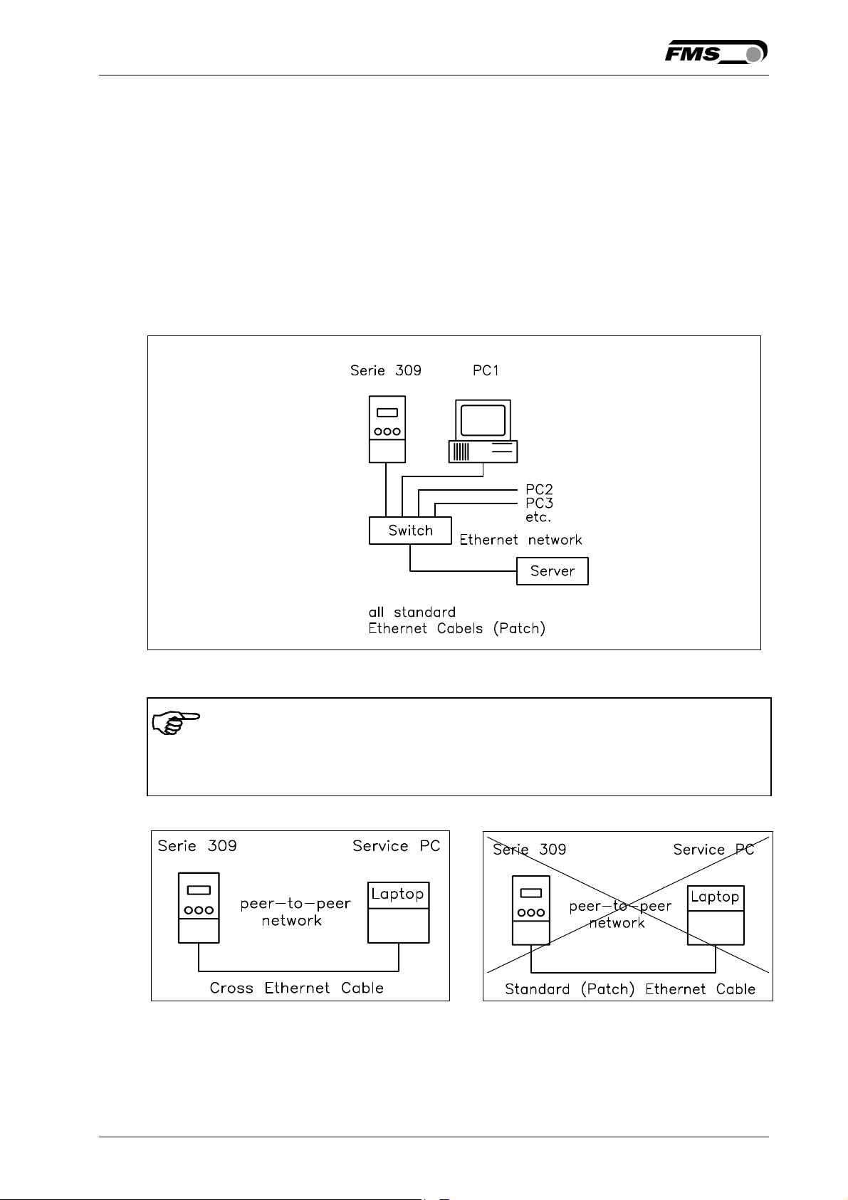
The BKSZ309 web guide controller can be embedded in an Ethernet network and the
parameter setting can be done over this network by means of a web browser
(Internet Explorer 7). The devices have a static IP-address that can be set over the
user interface. The IP-address is not automatically received over DHCP.
The parameter setting can also be carried out with a desktop- or laptop computer via
a peer-to-peer connection (see paragraph 9.2)
Fig. 18 shows the BKS309 configuration in a LAN (Local Area Network).
Fig. 18: BKS309 embedded in a LAN EMGZ309001e
Note
Fig. 19 and 20 show the peer-to-peer connection between PC und BKS309. Please
be aware that for this configuration a cross-over-cable needs to be used.
Fig. 19: Correct connection with crossover-cable. E309002e
Fig 20: Connection with wrong cable
E309003e
14.08.2018 41
Page 42
Operating Manual BKS309.MS
9.1 Parameterization in a Network via Web Browser
Before the parameterization of the BKS309 it must be certain that the BKS309 uses
an IP address in a static block. For the integration of a BKS309 web guide controller
in your Ethernet network please contact your IT system administrator.
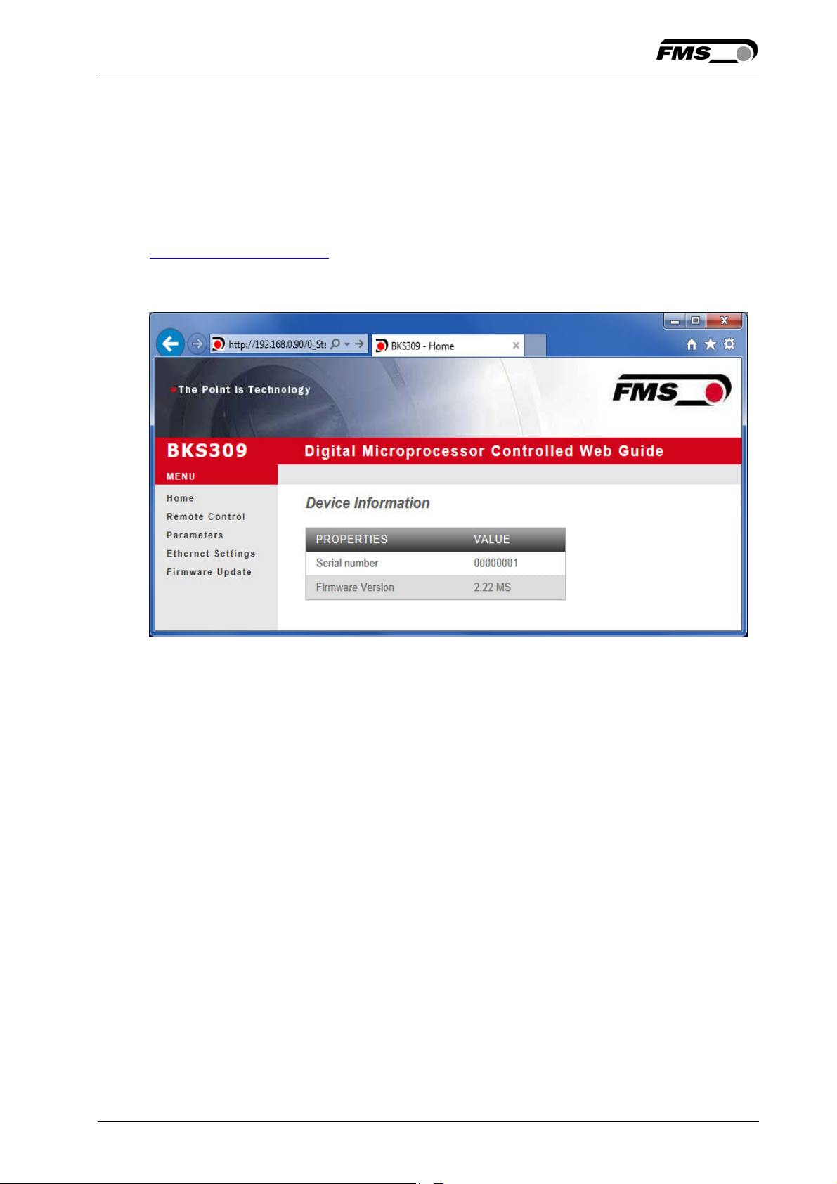
Once the BKS309 was integrated in the network you can address the device e.g. with
http://192.168.000.090 . After establishing the link, the screen Fig. 21 will open up.
Fig. 21: Serial number and device information Home.jpg
With the menu on the left side of the screen you can navigate through the web page.
14.08.2018 42
Page 43
Operating Manual BKS309.MS
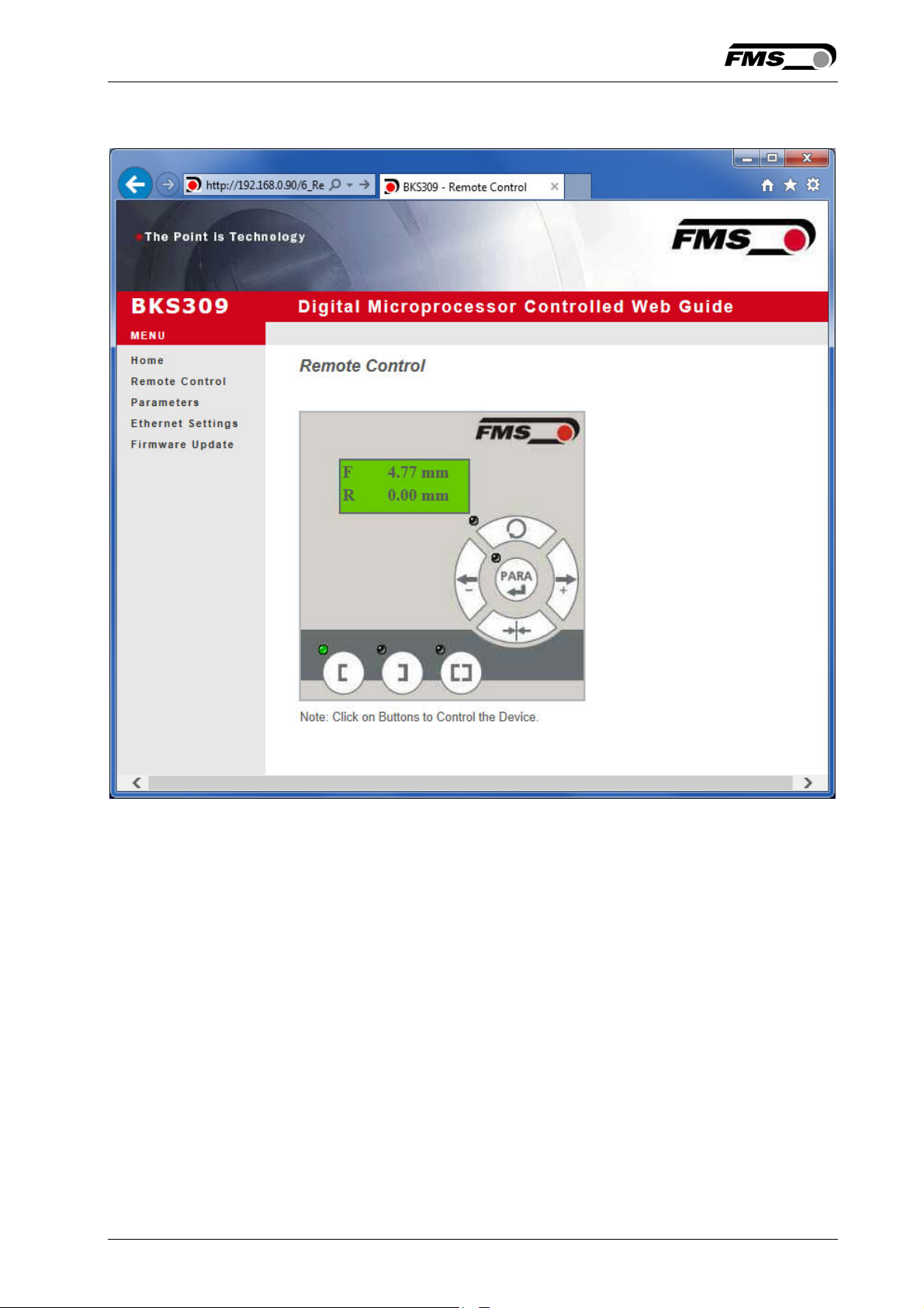
Fig. 22: Parameter setting and Remote Control Remote Control
14.08.2018 43
Page 44
Operating Manual BKS309.MS
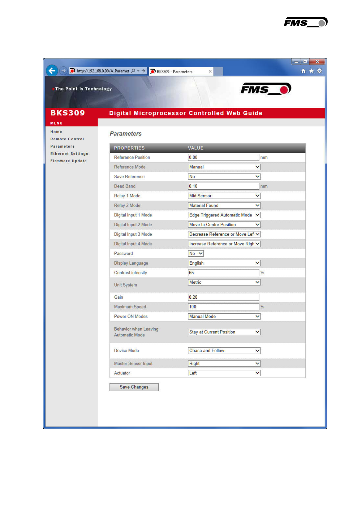
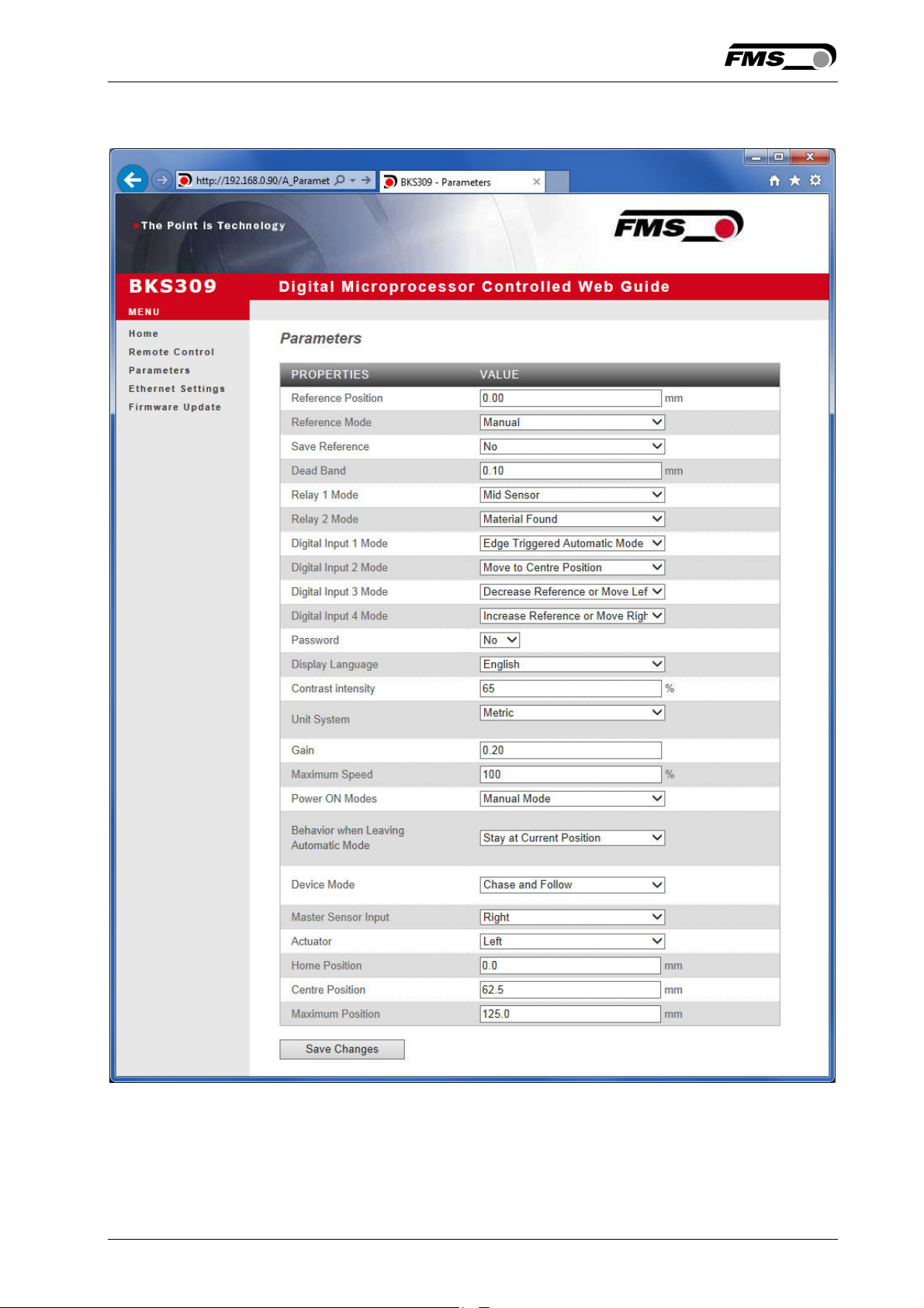
Fig. 23: Parameter list webMASTER Steering Frames wMASTER.jpg
14.08.2018 44
Page 45
Operating Manual BKS309.MS
Fig. 24: Parameter list winderGLIDE Actuators wGLIDE.jpg
14.08.2018 45
Page 46
Operating Manual BKS309.MS
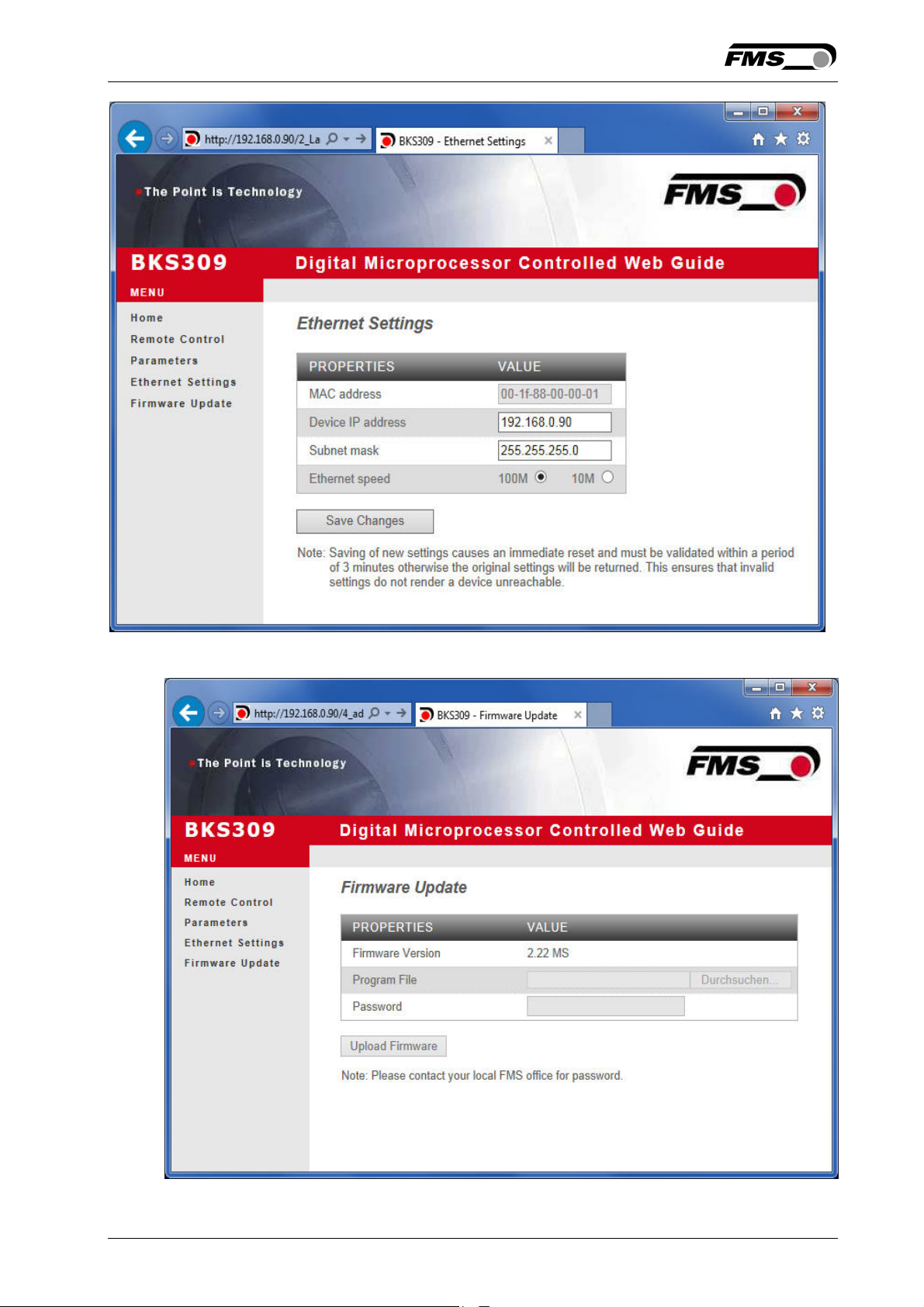
Fig. 25: Ethernet settings and device addresses Ethernet Settings
Fig. 26: Firmware update Firware Updates
14.08.2018 46
Page 47
Operating Manual BKS309.MS
9.2 Parameterization via a PC (peer-to-peer connection)
This paragraph describes the procedure for setting up a desktop or laptop computer
to communicate with FMS BKS309 web guide controller.
Before connecting the FMS BKS309 controller with a “cross-over-cable” directly to a
PC, the computer must be configured with a “static” IP address. If the BKS309
controller is connected to a network by using e.g. a switch, the following procedure is
not necessary. To establish the connection between your PC and the BKS309 follow
the steps below
Setup in Microsoft Windows XP:
1. Click on the Start button (lower left-hand corner of the screen)
2. Click on Control Panel
3. Double click on Local Area Network
4. Right click on the network adapter that is used for the connection.
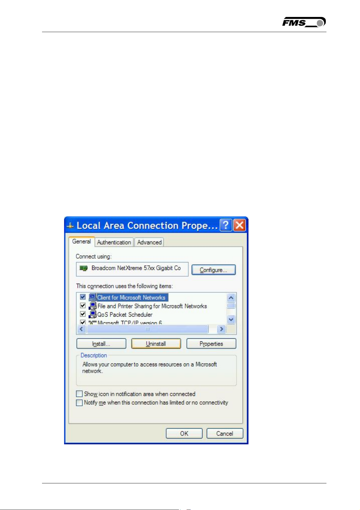
5. Click on Properties on the pop up menu, the following dialog box “Local Area
Connection Properties” will appear.
14.08.2018 47
Page 48
Operating Manual BKS309.MS
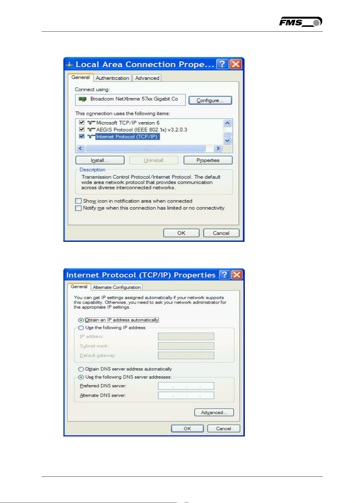
In the list box “This connection uses the following items:”, scroll down to “Internet
Protocol (TCP/IP). Select the “Internet Protocol (TCP/IP) and click “Properties” button.
The following dialog box will appear. Make sure the “General” tab is selected.
Select the radio button “Use the following IP address:”
14.08.2018 48
Page 49
Operating Manual BKS309.MS
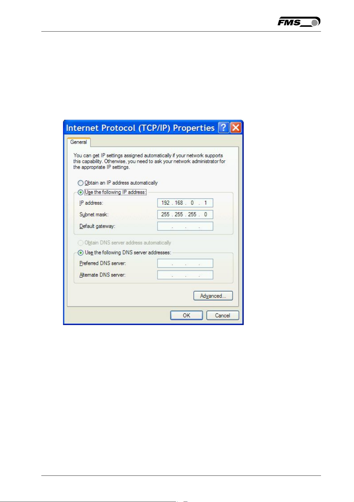
In the IP address box enter the IP address for the computer that could be
192.168.0.1.
In the Subnet mask, enter 255 255 255 000, as shown below.
Notice that the “000” in both boxes will change automatically to “0”.
The dialog box will change to look like the following:
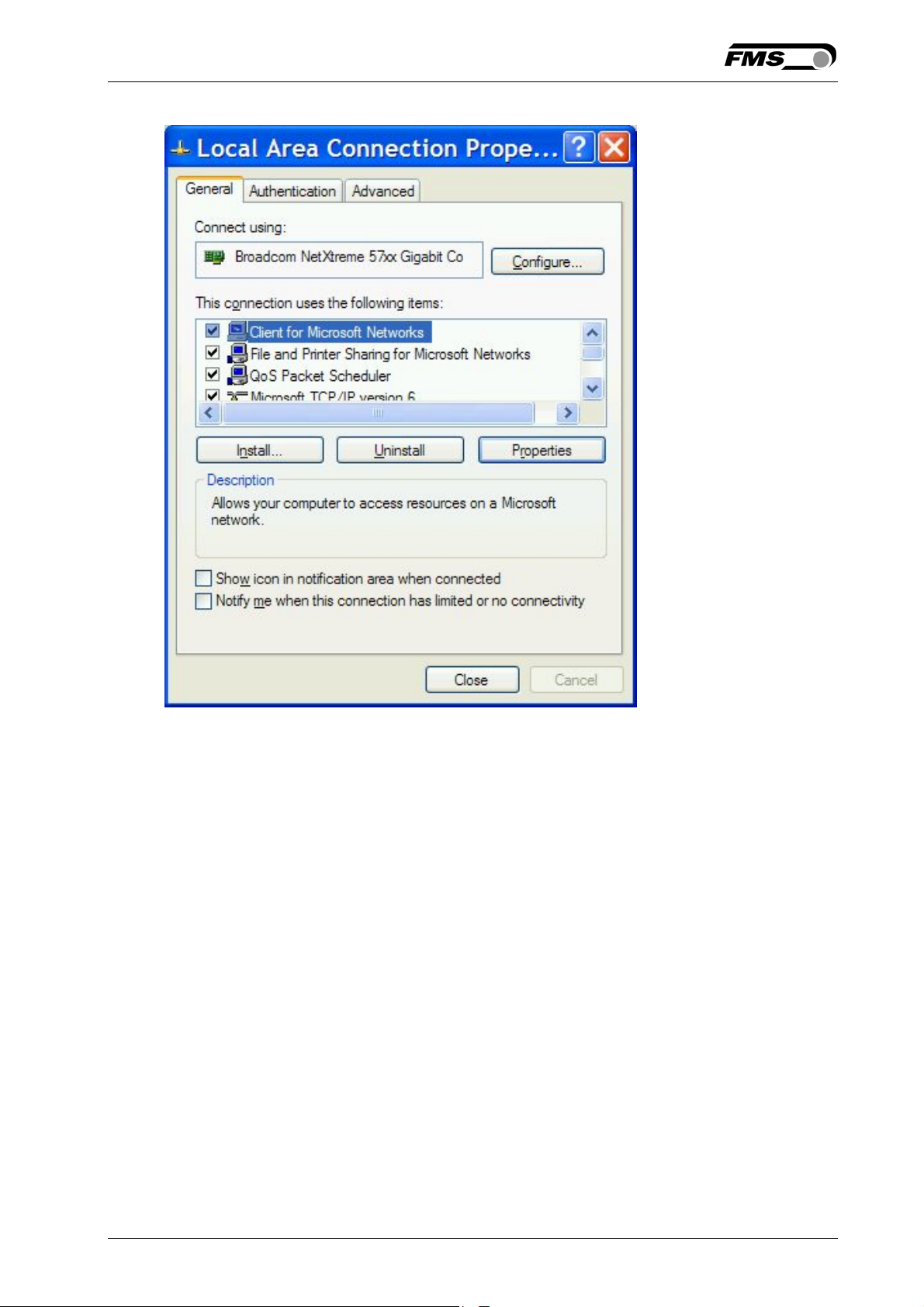
Click the “OK” button. The following dialog box will appear again:
14.08.2018 49
Page 50
Operating Manual BKS309.MS
Click on the “Close” button.
Close the “Network Connection” window
Close “Control Panel”
The computer is now ready to communicate with the BKS309 controller:
1. Connect the “cross over cable” to both the BKS309 and to the appropriate
port on the desktop or laptop computer.
2. Open Microsoft Internet Explorer or Mizilla Firefox.
3. The default IP address for the BKS309 is 192.168.000.090 as long as it was
not changed over the operating penal. Enter the IP address in the address bar
and hit the Enter key. If a different IP address and subnet mask is configured
at the BKS309 make sure that the computer is setup appropriate.
4. The screen Fig. 21 will open up. Continue then with the procedure described
in 9.1 “Parametrization in a Network via a Web Browser”.
14.08.2018 50
Page 51
Operating Manual BKS309.MS
10 Mechanical Dimensions
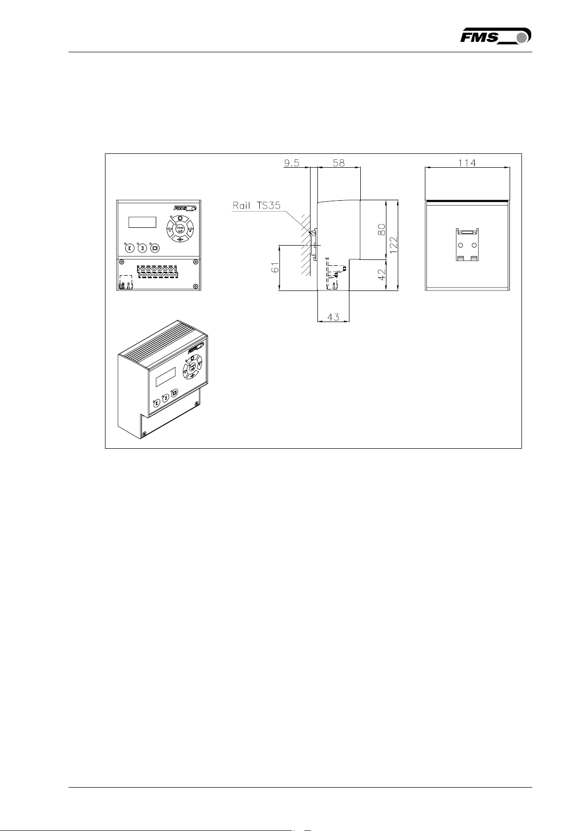
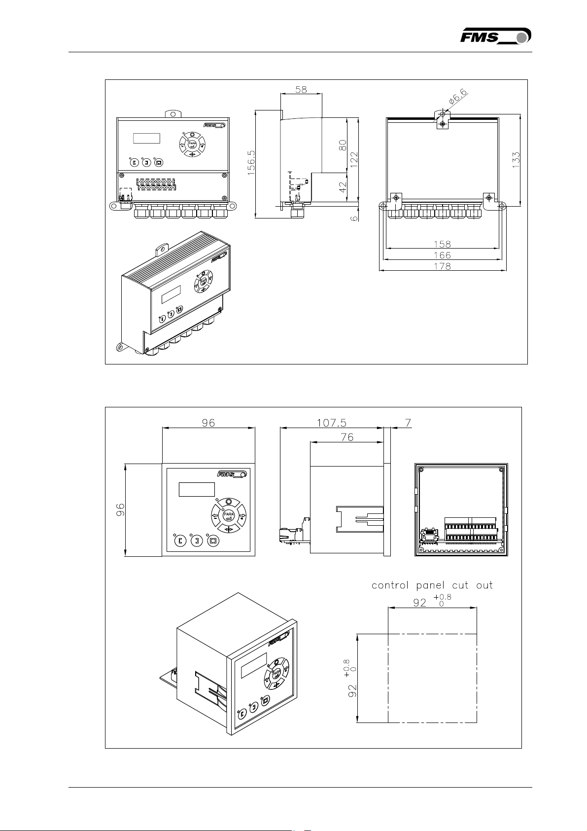
The BKS309 series is available in three different housing options. The mechanical
dimensions can be seen in the following pages.
Fig. 27: Outline Drawing BKS309.R rail mount housing K309006e
14.08.2018 51
Page 52
Operating Manual BKS309.MS
Fig. 28: Outline Drawing BKS309.W wall mount housing K309008e
Fig. 29: Outline Drawing BKS309.S panel mount housing K309007e
14.08.2018 52
Page 53
Operating Manual BKS309.MS
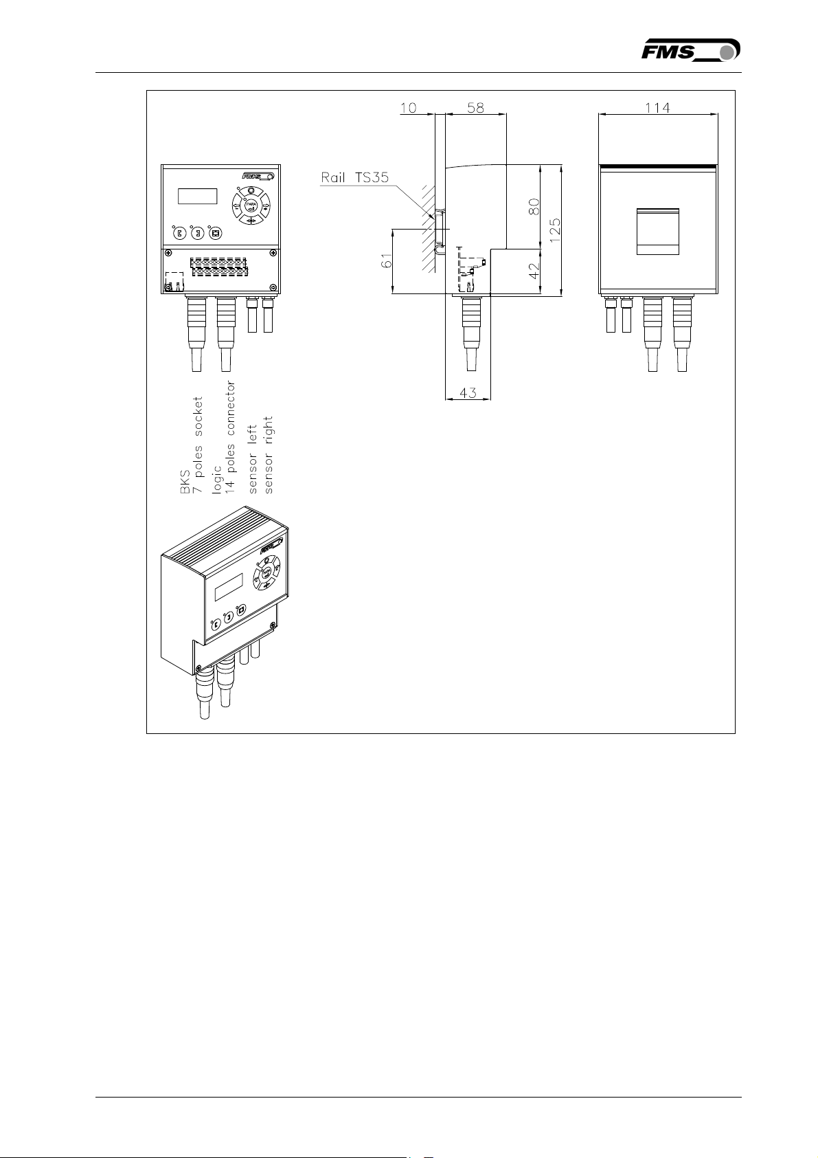
Fig. 30: Outline Drawing BKS309.R.C for DIN real mounting with connectorsK309016e
14.08.2018 53
Page 54

Operating Manual BKS309.MS
11 Trouble Shooting
Error Cause Corrective action
Edge outside
detection band
BKS guides web
edge immediately
out of the sensor
Sensor is connected
Steering frame
does not move
No signal; cable
No signal; sensor
No response of
the interface
Edge has moved
outside the sensor
detection band
Sensor is mounted on
the wrong side
to the wrong socket
No signal; sensor not
correctly connected
interruption
defect
Wiring not correct Check wiring
Adjust sensor more accurately to the
web edge;
Adjust reference position less during
automatic operation
Mount sensor to the correct side (right
sensor for „Edge right“, etc.)
Connect sensor plug to the correct
socket (left plug to left socket, etc.)
Connect sensor correctly according to
screw terminal arrangement and
installation guide
Replace cable or send sensor to FMS
Send sensor to FMS; use other sensor
Display shows
nothing, frame
doesn’t react
Power supply defect Check or correct power supply
Electronic control unit
Frame moves
abrupt to one of
the end positions
Fuse blown Replace Fuse on power supply board
installation
Contact FMS customer service
defect
Stepper motor driver
defective
Exchange actuator of the frame.
Contact FMS service department for
spare parts and installation guide.
14.08.2018 54
Page 55

Operating Manual BKS309.MS
12 Technical Specification
Cycle time processor 1ms
Drive of steering
frame
Dead band 0…2mm, adjustable in 0.1mm steps
Position reference ±5mm, adjustable in 0.1mm steps
Control modes edge left / edge right / center guiding / line guiding
Interface Web browser Ethernet Explorer 7 or higher
Operation 3 keys and 5–key wind rose pad
Analogue inputs 2 inputs 0...10V (for sensors)
Digital inputs 4 dig. inputs 24VDC galvanic insulated
Relay outputs 2 relay outputs. DC: 220V/2A/60W; AC:250V/2/62.3VA
Supply voltage 18…30 VDC (Vnom.= 24 VDC),
Temperature range -10 ... 60°C (14…140°F)
Protection class IP 30 (Standard) / IP65 (.W), IP00 (.S)
Stepper motor. Power amplifier 24V integrated in
housing
version .ACV 85…264 VACV / 80W
14.08.2018 55
Page 56
Operating Manual BKS309.MS
FMS Force Measuring
Systems AG
Aspstrasse 6
8154 Oberglatt (Switzerland)
Tel. 0041 1 852 80 80
Fax 0041 1 850 60 06
[email protected]
www.fms-technology.com
FMS USA, Inc.
2155 Stonington Avenue
Suite 119
Hoffman Estates,, IL 60169
(USA)
Tel. +1 847 519 4400
Fax +1 847 519 4401
fmsusa@fmstechnology.com
FMS (UK)
Aspstrasse 6
8154 Oberglatt
(Switzerland)
Tel. +44 (0)1767 221 303
[email protected]
FMS (Italy)
Aspstrasse 6
8154 Oberglatt (Switzerland)
Tel. +39 02 39487035
[email protected]
14.08.2018 56
 Loading...