

Page 1

Operating Manual BKS015
Steering Frame with Integrated Digital Controller
for Web Guiding
Version 1.81 11/2018 NS
Firmware Version 1.71
Diese Bedienungsanleitung ist auch in Deutsch erhältlich.
Bitte kontaktieren Sie Ihren nächstgelegenen FMS Vertreter.
© by FMS Force Measuring Systems AG, CH-8154 Oberglatt – All rights reserved.
Page 2

Operating Manual BKS015
Table of Contents
1 Safety Instructions ................................................................................... 2
1.1 Description Conditions 2
1.2 List of Safety Instructions 3
2 System Description .................................................................................. 4
2.1 Functional Description 4
2.2 Steering Frame 4
2.3 Web Guide Controller 4
2.4 Sensors 5
2.5 Cables 5
3 Quick Installation Guide ........................................................................... 6
3.1 Preparations for Set-up 6
3.2 Installation Procedure 6
4 Installation and Wiring ............................................................................. 7
4.1 Mounting the Steering Frame 7
4.2 Mounting the Sensors 7
4.3 Connecting the BKS015 8
4.4 Connector and Screw Terminal Arrangement 8
5 Configuring the System .......................................................................... 10
5.1 Powering up the BKS015 10
5.2 Adjustment of the Sensors 10
6 Operation ................................................................................................ 10
6.1 Operation Panel 10
6.2 Basic Instructions for Operation and Parameter Setting 11
6.3 Operating the Web Guiding System via the Front Panel 11
6.4 Operation in Automatic Mode 12
6.5 Operation in Manual Mode 13
6.6 Entering the Parameter Setting Mode 13
6.7 Description of the LED-row 14
6.8 Sensor Detection Range and Reference Position 15
7 Description Parameters ......................................................................... 15
7.1 Description Operation Parameters 15
7.2 Description of System Parameters 20
7.3 Reset to Default Parameter Set 21
8 Parameter Setting via a PC .................................................................... 22
8.1 Parameterization in a Network via Web Browser 24
8.2 Parameterization via a PC (peer-to-peer connection) 28
9 Mechanical Dimensions ......................................................................... 32
10 Trouble Shooting .................................................................................... 34
11 Technical Specification .......................................................................... 35
1 Safety Instructions
1.1 Description Conditions
a) Danger of health injury or loss of life
26.11.2018 2
Page 3
Operating Manual BKS015
Danger
This symbol refers to high risk for persons to get health injury or loss life. It has to
be followed strictly.
b) Risk of damage of machines
Caution
This symbol refers to information, that, if ignored, could cause heavy mechanical
damage. This warning has to be followed absolutely.
c) Note for proper function
Note
This symbol refers to an important information about proper use. If not followed,
malfunction can be the result.
1.2 List of Safety Instructions
Proper function of the FMS web guide is only guaranteed with the recommended
application of the components. In case of other arrangement, heavy malfunction
can be the result. Therefore, the installation instructions on the following pages
must be followed strictly.
Local installation regulations are to preserve safety of electric equipment. They are
not taken into consideration by this operating manual. However, they have to be
followed strictly.
Make sure that the sensor(s) are connected properly to the electronic unit by
means of the delivered cables. For left / right orientation please refer to Fig. 2. If
the connections are crossed over, malfunction can be the result.
System parameters are factory settings and should not be changed without
contacting the service department of FMS. An unauthorised change can cause
malfunctions in the system or damage in the machine
26.11.2018 3
Page 4
Operating Manual BKS015
2 System Description
2.1 Functional Description
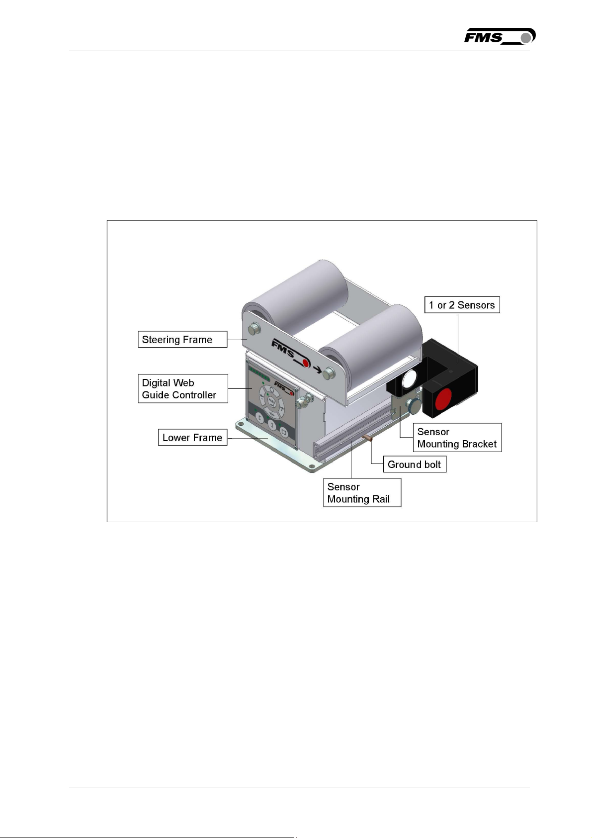
Figure 1 shows a typical web guiding system with its basic components.
The sensors measure the position of the web edge and send this information as an
analogue signal to the built-in web guide controller unit. The control compares the
position feedback signal with the reference. If the difference of these two values is
higher then the stored dead band value, the steering frame will be adjusted.
Fig. 1: Basic BKS015 system K015006e
2.2 Steering Frame
The steering frame consists of a fixed lower and a moveable upper frame that
supports the rollers. The upper frame is activated by a stepper motor. The rollers
are manufactured and balanced according to customer specification. End positions
are controlled by hall sensors. The material sensors are mounted on the lower
frame by means of a bracket array and are easily adjustable to the web width.
2.3 Web Guide Controller
The micro-processor based electronic control unit handles all calculations and
communications tasks. Three buttons and a five key wind-rose serve as the manmachine interface. Parameter setting can be performed via the front panel keys or
through a Web Browser (IE 7.0 or higher). The controller is then either connected to
a network (e.g. Ethernet) or via a peer-to-peer configuration to a laptop or local PC.
All parameters are stored in a none-volatile EEPROM memory.
26.11.2018 4
Page 5

Operating Manual BKS015
2.4 Sensors
Optical sensors (AZS04) and ultrasonic sensors (US01B) are available from FMS to
work in conjunction with the BKS015 system. These sensors provide a signal of
0...10V. With them edge and center applications can be covered. A wide range of
materials including opaque, transparent, open weave textiles and metallic webs can
be detected.
2.5 Cables
The power supply cable enters to the web guide via a PG-gland connection. For each
sensor a dedicated orange cable is delivered.
26.11.2018 5
Page 6

Operating Manual BKS015
3 Quick Installation Guide
The set-up of the BKS015 web guide including controller unit is limited to only
mounting the devices on the machine frame, wiring and powering up system.
3.1 Preparations for Set-up
• Prepare your machine frame to integrate the BKS015 web guide. The web guide
is mounted on the machine by means of the 4 holes on its base plate. Refer to
Fig. 21 for the mechanical dimensions and mounting holes of the BKS015.
• Check your system requirements such as:
– Desired guiding form (edge or centre guiding)
– Supply conditions
• Draw the wiring diagram for your configuration (ref. to 4.3 “Connecting the
BKS015“ and chapter 4.4 “Connector and Screw Terminal Arrangement”)
• If required, determine special parameters (ref. to 7.1 “Description Operation
Parameters”)
3.2 Installation Procedure
1. Mount and ajust your material sensor(s) to the steering frame (ref. to chapter 4.2)
2. Mount the web guide to the machine frame
3. Connect the sensor(s) to the electronic unit.
4. Make sure the power supply voltage is in the range 18 to 36V DC (Vnom= 24V)
5. Power your system on
6. If required, make additional settings (ref. also to chapters 6.4 to 6.8)
26.11.2018 6
Page 7

Operating Manual BKS015
4 Installation and Wiring
Caution
Proper function of the FMS web guides and actuators is only guaranteed with the
recommended application of the components. Other arrangements can cause
heavy malfunctions. Therefore, the installation instructions on the following pages
must strictly be followed.
Caution
Local installation regulations are to preserve safety of electric equipment. They are not
taken into consideration by this operating manual. However, they have to be followed
strictly.
4.1 Mounting the Steering Frame
The mounting orientation of the steering frame (indicated by an arrow), must
correspond with the web running direction. The lower frame is mounted with four
M5 screws to the machine frame. The machine must be prepared to accept the M5
mounting screws.
The steering frame must be connected to earth ground. Ensure that the base plate
of the steering frame has direct contact with the grounded machine frame. In
addition the ground bolt (see Fig. 1) must be connected to the machine earth.
Caution
Bad earth connection may cause electric shock to persons, malfunction of the total
system or damage of the control unit. It is vital to ensure that there is a proper and
secure earth connection.
4.2 Mounting the Sensors
The sensors will be mounted with brackets on a rail to the lower frame of the web
guide
They have to be installed after the outbound roller. Mount them as close as possible
to the steering frame (see Fig. 2). The sensors are connected to the web guide
controller by means of the delivered orange cables. Refer to the operation manual
AZS01, US01B for further information about the sensors.
26.11.2018 7
Page 8

Operating Manual BKS015
Definition of Left and Right:
Left and right are always seen in direction of the running web (see Fig. 2).
Fig. 2: Position of the sensors according to the web K400005e
Sensors of the type AZS must be mounted with its narrow side (thinner leg) on the
side of the steering frame
Caution
Make sure that the sensor(s) are connected properly to the electronic unit by
means of the delivered orange cables. For left / right orientation please refer to Fig.
2. If the connections are crossed over, malfunction can be the result.
4.3 Connecting the BKS015
The power supply unit musst deliver a voltage from 18 to 36V DC (Vnom= 24V).
Connect the cable coming out of the PG-gland to your power supply unit.
Wire colour Signal
brow 24 VDC
blue GND
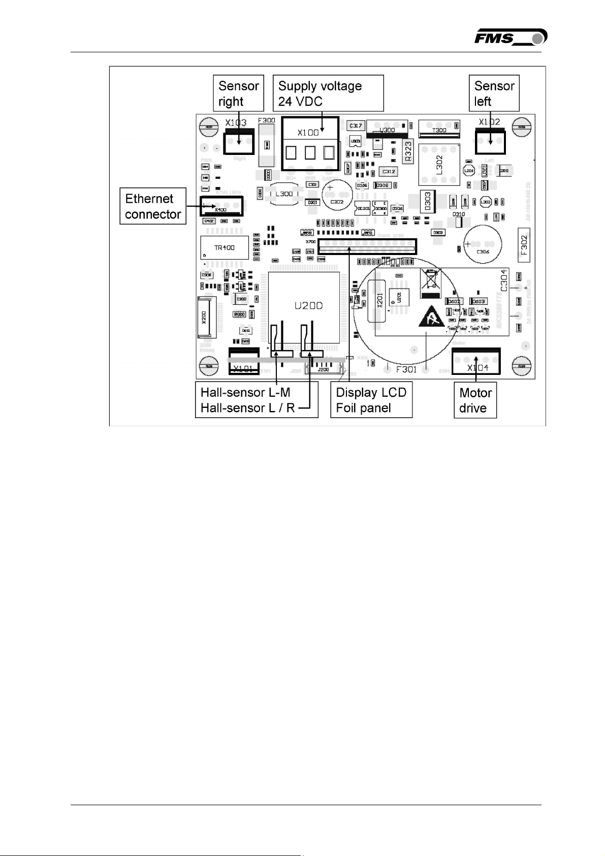
4.4 Connector and Screw Terminal Arrangement
26.11.2018 8
Page 9
Operating Manual BKS015
Fig. 3: Terminal arrangement on processor board K015008e
26.11.2018 9
Page 10
Operating Manual BKS015
5 Configuring the System
After having mounted and wired the web guide on the machine, the system can now
be configured to the specific requirements of the application.
5.1 Powering up the BKS015
1. Make sure the power supply delivers a voltage of 18…36 VDC (Vnom= 24V)
2. Check, if the web is in the detection range of the sensors.
3. Switch-on your power supply
4. The web guide starts-up in Manual Operating Mode.
5.2 Adjustment of the Sensors
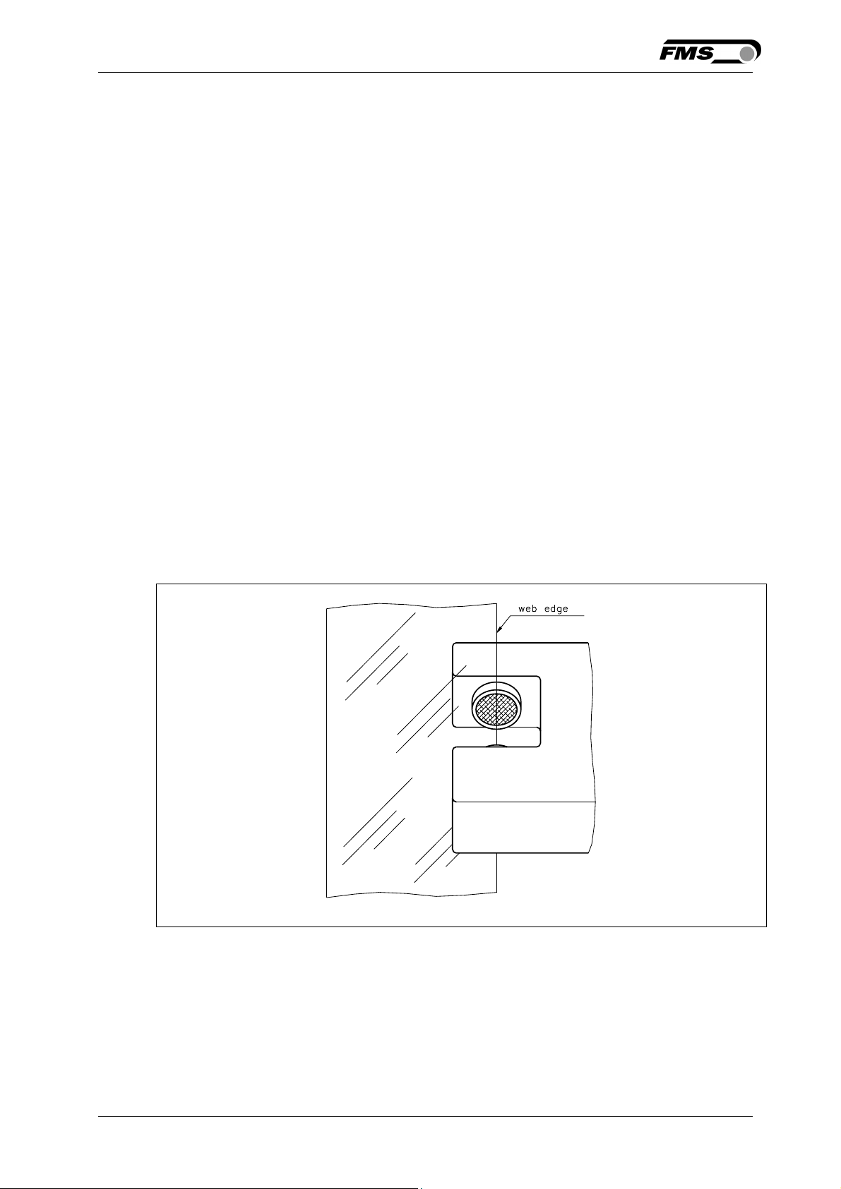
Align sensor axis to the web edge:
Loosen the fixing nut on the bracket and adjust the sensor. Fix the sensor in the
new position. The sensor will be properly positioned, if the web edge goes through
the sensor axis (center of active window; ref. to Fig. 4).
Fig 4: Alignment of the sensor axis to the web edge K100004e
.
6 Operation
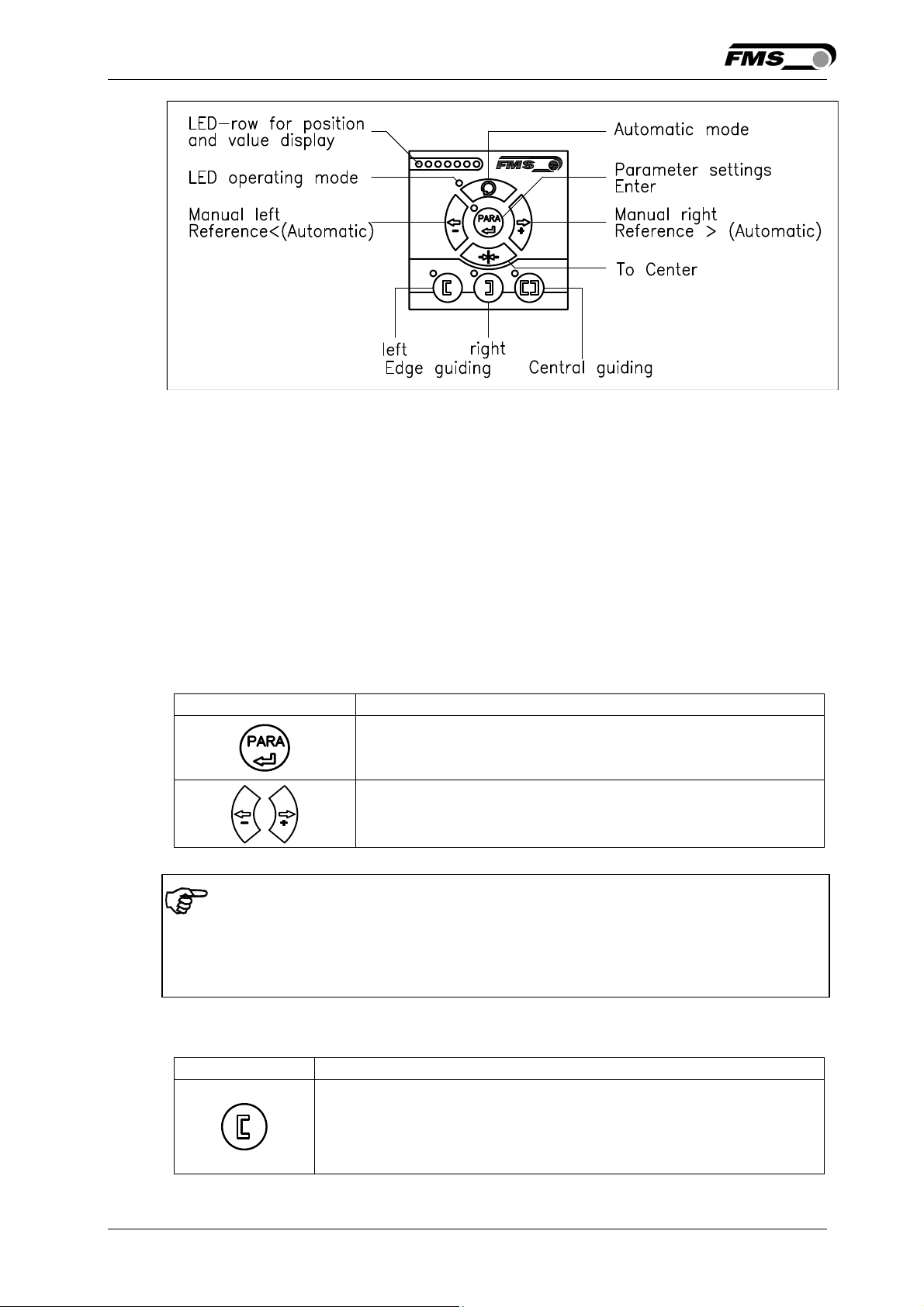
6.1 Operation Panel
26.11.2018 10
Page 11
Operating Manual BKS015
t
Fig. 5: View of the Operation Panel K015003e
6.2 Basic Instructions for Operation and Parameter Setting
The web guide controller has three operation mods:
• Operation Mode
• Parameter Setting Mode (e.g. Dead Band)
• Change Mode (change of Reference Position)
Parameter setting can be performed via the keys on the front panel or via a web
browser. When using the front panel, the user can toggle between these modi by
pressing the corresponding key or key combination. The Parameters are described
in chapter 7.1 “Description of Operation Parameters”). The keys have the following
functions:
Key Key function during parameter setting
Enter
Increase or decrease the values.
Permanent pressing of the keys expedites the changing speed.
Note
To make the settings easier for the operator, there is visual help in form of LED row.
The pattern on the LED row indicates the setting range (ref. to chapter 6.7
“Description of the LED row).
6.3 Operating the Web Guiding System via the Front Panel
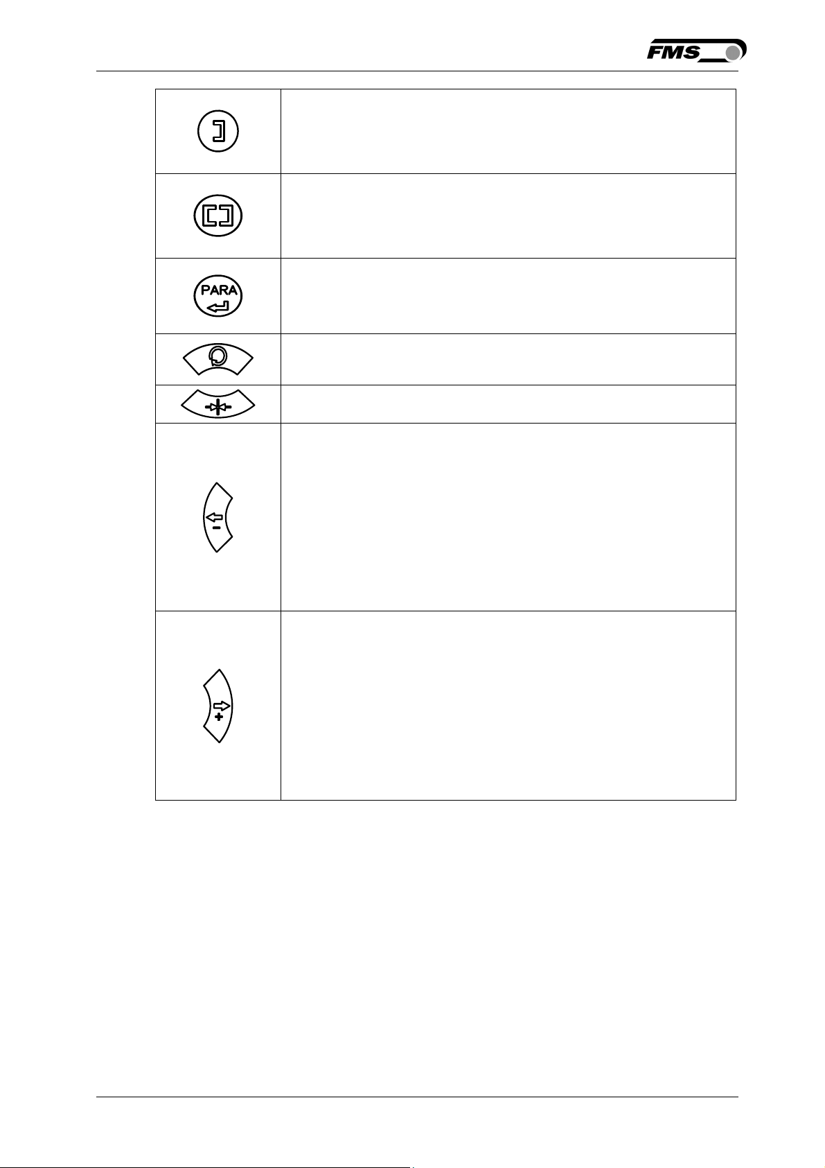
Key Key function during operation
The sensor is mounted on the left side of the frame and
controls the material on the left edge or on the line, if a line
sensor is used. One sensor is necessary. The LED indicates
he left edge guiding mode.
26.11.2018 11
Page 12
Operating Manual BKS015
t
t
The sensor is mounted on the right side of the frame and
controls the material on right edge or on the line, if a line
sensor is used. One sensor is necessary. The LED indicates
he right edge guiding mode.
Two sensors are mounted on both sides of the frame. The
frame is controlled in a way that the material position is kept
centered with regard to both sensor positions. The LED
indicates the centre guiding mode.
Key to enter the Parameter Setting Mode. Hold the key for
longer then 3 sec. The LED above the PARA key lights. A
second press for longer then 3 sec. on the PARA key will store
he value (ref. to 6.6 “Entering the Parameter Setting”)
With this key you can select between automatic or manual
mode. The LED indicates the automatic mode.
Drive to center position. The frame moves to the center
Position. This function is only available in manual mode.
In manual mode the frame will move to the left in 0.1mm
steps by pressing the button once. By pressing the button
longer than 1 sec. it will continuously move the frame to the
left.
In automatic mode the Reference Position will be adjusted to
the left in 0.1 mm steps by pressing the button once. Pressing
the button longer than 1 sec. it will continuously move the
Reference Position to the left (see chapter 6.4)
In parameter setting mode: Pressing the button reduces
continuously the parameter value.
In manual mode the frame will move to the right in 0.1mm
steps by pressing the button once. By pressing the button
longer than 1 sec. it will continuously move the frame to the
right.
In automatic mode the Reference Position will be adjusted to
the right in 0.1 mm steps by pressing the button once.
Pressing the button longer than 1 sec. it will continuously
move the Reference Position to the right. (see chapter 6.4) “.
In parameter setting mode: Pressing the button increases
continuously the parameter value.
Fig. 6: Table of key functions
6.4 Operation in Automatic Mode
26.11.2018 12
Page 13
Operating Manual BKS015
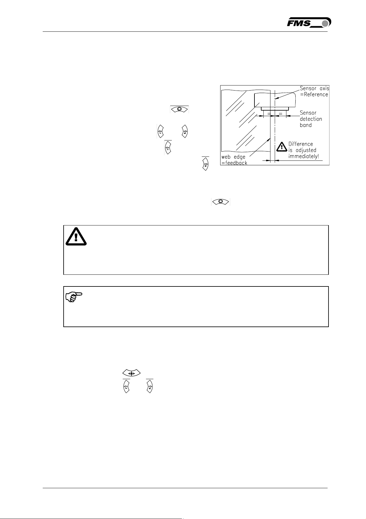
In Automatic Mode the web guide controller starts to guide the web to the Reference
Position and to hold this guiding point.
For edge guiding operations the Reference Position is in the middle of the sensor
detection range (Fig. 7). For centre guiding the Reference Position is in the middle
between the two sensor axis.
This Reference Position can be adjusted as
follows:
• Start automatic mode with the key.
• The Reference Position can be adjusted in
0.1mm steps by using the and keys.
• For left sensor operation the key causes
the web moving inside the sensor. The
key causes the web moving outside the
sensor. Using right sensor operation or
center guiding the setting behaves contrariwise (refer also to Fig. 10, 11 and 12)
• Terminate the automatic mode by using the key again.
Fig. 7: Reference position at
automatic start K100005e
Caution
If web is not running, it can’t be guided properly to the Reference Position. The
steering frame moves in the limit-of-travel position and may damage the web. Start
automatic mode only when web is slowly running
Note
If the web leaves the sensor detection range, control is no longer effective. Hold the
web edge strictly inside the sensor detection band.
6.5 Operation in Manual Mode
In Manual Mode several operations and settings can be carried out (see Fig. 6):
• Center position : The steering frame will return to center position.
• Frame position and : The steering frame can be adjusted in 0.1mm steps. If
key is held, the steering frame will move continuously to chosen direction.
• Parameter Setting Mode: The Parameter Setting Mode can only be entered in
Manual Operation.
6.6 Entering the Parameter Setting Mode
To enter the Parameter Setting Mode the web guide controller must be in the
Manual Mode. In the Automatic Mode only the reference value can be changed.
26.11.2018 13
Page 14
Operating Manual BKS015
• Press the key for longer then 3 sec. The LED above the key will light
indicating that the controller entered the Parameter Setting Mode. In this mode
the Dead Band parameter can be adjusted (see chapter 7 “Description of
Operation Parameters”)
• With the keys and the desired band can be adjusted (see Fig. 9)
• Press the key again to confirm the setting and leave the Parameter Setting
Mode.
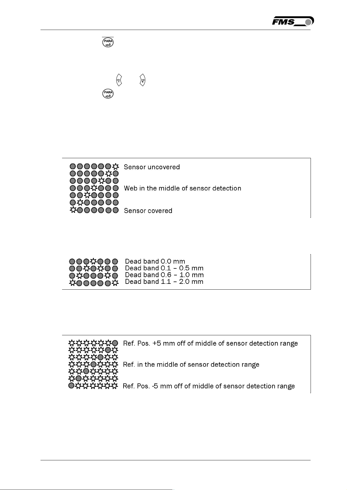
6.7 Description of the LED-row
☼
= LED illuminated ● = LED off
a) Automatic or manual mode. LED control of web position
Fig 8: LED row indicates material position K015004e
b) Setup mode for the adjustment of Dead Band
Fig 9: LED indication of Dead Band values K015005e
c) Setup mode for the adjustment of the Reference Position for left sensor
operation. Setup is only possible in automatic mode with the direction keys.
Fig 10: LED indication of Reference Position values (left sensor) K015013e
d) Setup mode for the adjustment of the Reference Position for right sensor
operation and center guiding. Setup is only possible in automatic mode with the
direction keys.
26.11.2018 14
Page 15
Operating Manual BKS015
Fig 11: LED indication Reference Position values (right sensor) K015014e
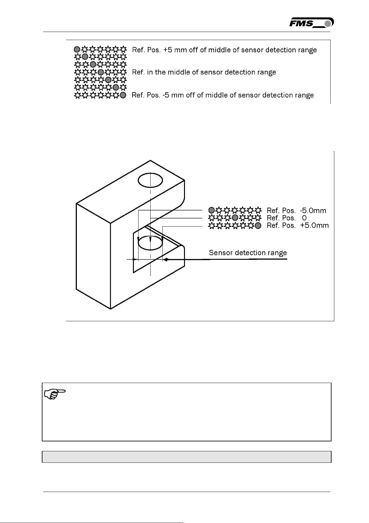
6.8 Sensor Detection Range and Reference Position
Fig. 12: View of the Sensor Detection Range K015007e
7 Description Parameters
7.1 Description Operation Parameters
Note
The first three parameters [RefPos], [RefMode] and [DeadBand] in the parameter list
below can be changed via the front panel (ref. to chapters 6.4 to 6.8). All other parameters
can only be accessed and changed vial the build-in web browser (ref. to chapter 8
“Parameter Setting via a PC”)
Adjusting Reference Position [Ref Pos]
Purpose: The [RefPos] parameter determines the reference position within
the sensor detection range. This reference point can also be
26.11.2018 15
Page 16

Operating Manual BKS015
adjusted over the front panel as described in chapter 6.2
“Automatic Operation”. The Reference Position is kept stored
until the next power-on.
Range: -5.0 to +5.0 Default: 0.0
Increment: 0.1 Unit: [mm]
Note
By pressing the keys and at the same time for longer then 1
sec., the Reference Position will reset to default
Setting Reference Mode [Ref Mode]
Purpose: This parameter determinates how the Reference Position is
defined. This can either be the position that is defined with
parameter [Ref Pos] or the actual material position within the
sensor when the controller is switched to automatic operation.
Two settings are possible:
Setting: [Manual]
Purpose: If [Manual] is chosen, the reference is taken from the parameter
[RefPos].
Setting: Automatic [Auto]
Purpose: If [Auto] behaviour is chosen then the reference is determent by
taking the actual material position within the sensor when the
controller is switched to automatic operation.
26.11.2018 16
Page 17

Operating Manual BKS015
Dead band [DeadBand]
Purpose: This parameter defines the dead band tolerance. Dead band is a
free programmable range, in which the web may move freely
without the controller re-adjusting the frame. If the deviation is
higher than the tolerance, the web will be re-adjusted into the
range of the dead band. Keep in mind that: A [DeadBand] of e.g.
0.3mm“ results in a tolerance band of ±0.3mm.
Range: 0.0 to 2.0 Default: 0.0
Increment: 0.1 Unit: [mm]
Note
By pressing the two keys and at the same time for longer
then 1 sec. will reset the Dead Band to default value.
Unit System [Unit Sys]
Purpose: This parameter determines the unit system that is used when the
parameters are set via the web browser.
The user can choose between two settings.
Setting: [Metric]
Purpose: Settings in the web browser are carried out in metric units.
Setting: [Imperial]
Purpose: Settings in the web browser are carried out in imperial units.
Gain Setting [Gain]
Purpose: This parameter defines the gain of the feed back value.
Range: 0.02 to 2.00 Default: 0.20
Increment: 0.01 Unit: [ - ]
26.11.2018 17
Page 18

Operating Manual BKS015
Adjusting Correction Speed [AdjSpeed]
Purpose: This parameter determines the maximum used correction speed.
Range: 1 bis 100 Default: 100
Increment: 1 Unit: [%]
Power Modes [Power ON]
Purpose: This parameter determines the operation mode after power on.
The user can choose between three behaviours.
Setting: [Manual]
Purpose: The controller goes to Manual Operation Mode after power on.
Setting: Automatic [Auto]
Purpose: The controller goes to Automatic Operation Mode after power on.
Setting: Last Setting Used [Last Set]
Purpose: The controller restores the operation mode that was previously
chosen before power off.
Behaviour when leaving Automatic Mode [Auto→Man]
Purpose: This parameter determines the behaviour of the controller leaving
the automatic mode.
The user can choose between two behaviours.
Setting: [Manual]
Purpose: The controller stops guiding. The web guide is locked at the
current position (Manual Mode).
Setting: [Centre]
Purpose: The controller stops guiding. Afterwards the web guide moves to
the centre.
26.11.2018 18
Page 19

Operating Manual BKS015
[IP Addr]
Purpose: The parameter assigns an IP address to the controller. This
enables the user to communicate via a web browser with the
controller that is imbedded in a network. The IP address must be
entered in 4 separate blocks (IP Bl. 1; IP Bl. 2; IP Bl. 3; and IP Bl.
4)
Range: 0 to 255 Default: 192.168.0.090
Increment: 1 Unit: [ - ]
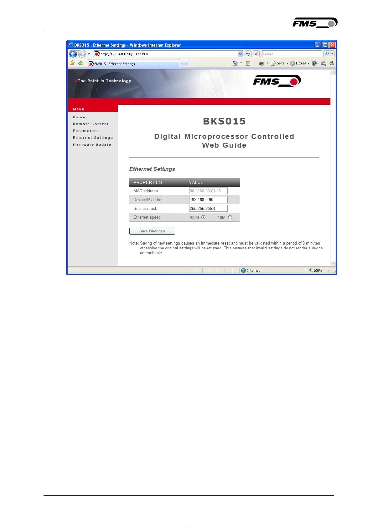
[Subnet]
Purpose: The parameter assigns the Subnet Mask of the controller in the
Ethernet network. This enables the user to communicate via a
web browser with the controller. The Subnet Mask must be
entered in 4 separate blocks (Sub. Bl 1; Sub. Bl 2; Sub. Bl 3; and
Sub. Bl 4).
Range: 0 to 255 Default: 255.255.255.0
Increment: 1 Unit: [-]
[LANSpeed]
Purpose: [LANSpeed] determines the data speed of the web guide
controller to communicate the receiver (Switch, Hub or PC).
Selection: 10 or 100 Default: 100
Unit: [MBPS]
26.11.2018 19
Page 20
Operating Manual BKS015
7.2 Description of System Parameters
Caution
System parameters are factory settings and should not be changed without contacting the
service department of FMS. An unauthorised change can cause malfunctions in the
system or damage in the machine.
Offset Centre [Offset><]
Purpose: This parameter adjusts the position of a steering frame exactly to
the centre.
Type: [One Hall]
Purpose: One hall sensor is used to detect the Home position, Middle
Position and Maximum Position.
Type: [Two Hall]
Purpose: Two hall sensors are used to detect the Home position, Middle
Position and Maximum Position.
Centre Position [CentrPos]
Purpose: The [CentrPos] parameter is only used with the position detection
system based on hall sensors. For all other position detection
system this parameter is not used and hence not displayed. The
parameter determines the centre position of the actuator spindle
in motor steps (measured from the left reference position). The
actuator stops at this position, if you press the centre key .
In Automatic Operation this parameter has no meaning.
Range: 0 to 10’000 Default: Factory setting
Increment: 1 Unit: [Step]
26.11.2018 20
Page 21

Operating Manual BKS015
Right Limit [RightLim]
Purpose: The [RightLim] parameter is only used with the position detection
system based on hall sensors. For all other position detection
system this parameter is not used and hence not displayed. The
parameter limits the maximum travel to the right side of the
actuator spindle in motor steps (measured from the left reference
position). In the operation or in manual mode this limit will never
be exceeded
Range: 0 to 10’000 Default: Factory setting
Increment: 1 Unit: [Step]
Drive Direction [DriveDir]
Purpose: This parameter determines the guiding orientation of the
controller. Usually stepper motors turn clockwise. This setting
changes the turning direction of the motor. There are two other
possibilities to change the guiding direction:
The user can choose between two settings
Setting: [Standard]
Purpose: [Standard] is chosen when standard motors and standard frames
are used.
Setting: [Invers]
Purpose: [Invers] is chosen when motors are used that turn anticlockwise.
7.3 Reset to Default Parameter Set
Factory settings of your BKS015 web guide controller can be re-established by
pressing a combination of two keys.
Hold the two keys + while powering -up the controller
26.11.2018 21
Page 22

Operating Manual BKS015
8 Parameter Setting via a PC
The BKS015 web guide controller can be embedded in an Ethernet network and the
parameter setting can be done over this network by means of a web browser
(Internet Explorer 7). The devices have a static IP-address that can be set over the
user interface. The IP-address is not automatically received over DHCP.
The parameter setting can also be carried out with a desktop- or laptop computer
via a peer-to-peer connection (see chapter 8.2)
Fig. 13: BKS015 configuration in a LAN (Local Area Network). K015009e
Note
Fig. 14 and 15 show the peer-to-peer connection between PC und BKS015. Use for
this configuration a cross-over-cable and not the standard patch Ethernet cable.
26.11.2018 22
Page 23

Operating Manual BKS015
Fig. 14: Correct connection with crossover-cable. K015010e
Fig 15: Connection with wrong cable
K05011e
26.11.2018 23
Page 24

Operating Manual BKS015
8.1 Parameterization in a Network via Web Browser
Before the parameterization of the BKS015 is done it must be certain that the
BKS015 uses an IP address in a static block. For the integration of a BKS15 web
guide controller in your Ethernet network please contact your IT system
administrator.
Once the BKS015 was integrated in the network you can address the device e.g.
with http://192.168.000.090 . After establishing the link, the screen Fig.16 will
open up.
Fig. 16: Serial number and device information
Home.jpg
With the menu on the left side of the screen you can navigate through the web
page.
26.11.2018 24
Page 25
Operating Manual BKS015
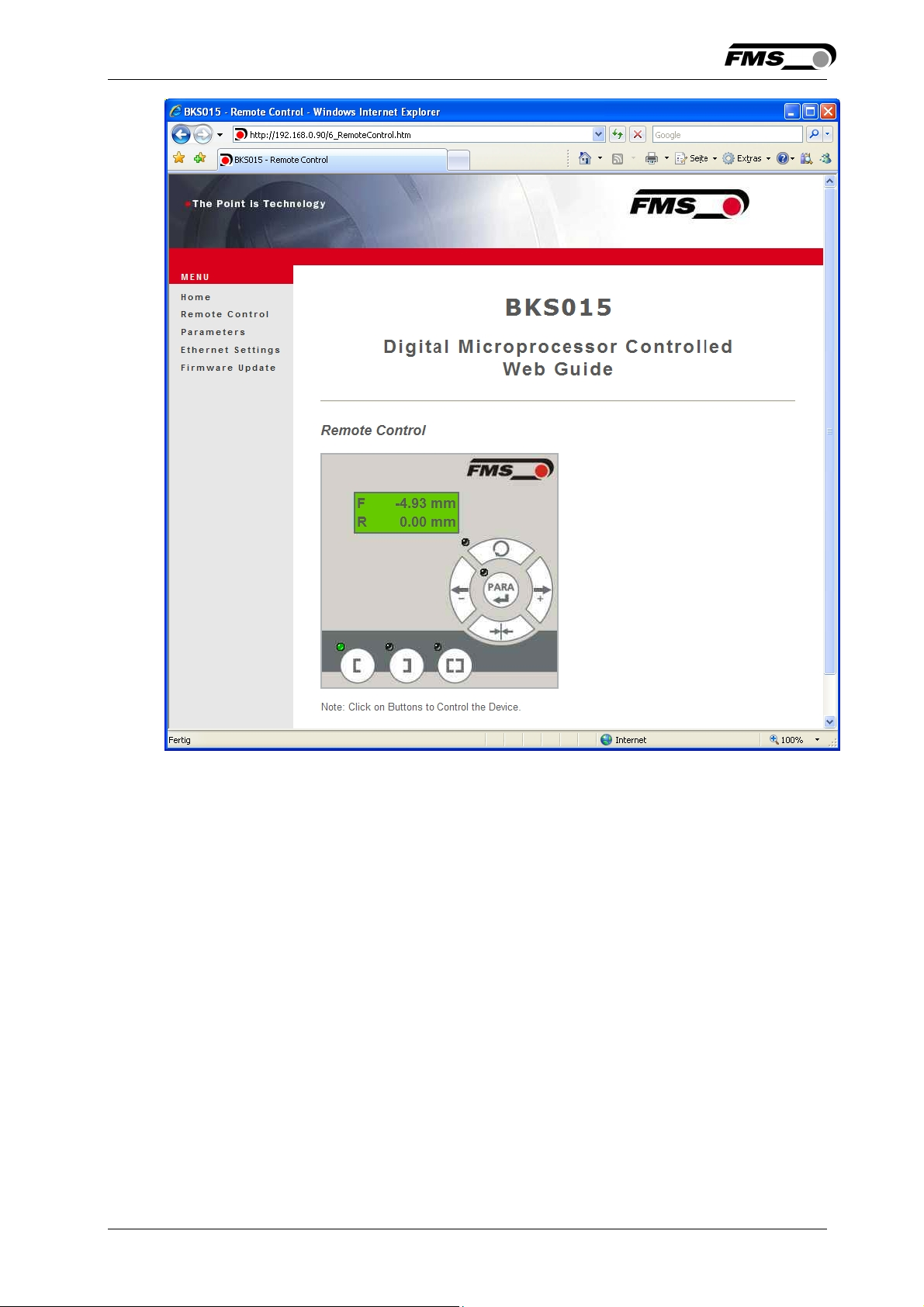
Fig. 17: Front panel for remote control purposes Remote Control
26.11.2018 25
Page 26
Operating Manual BKS015
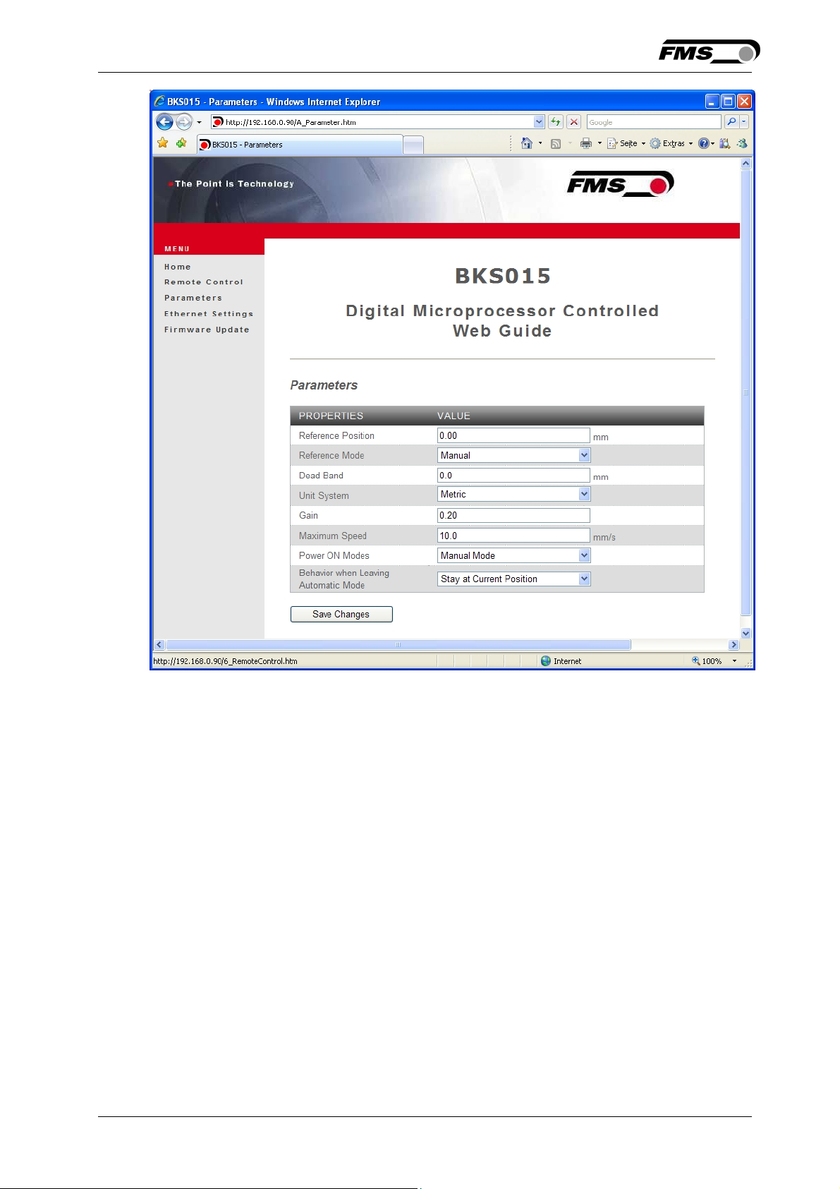
Fig. 18: Parameter list. Parameters can be changed Parameters
26.11.2018 26
Page 27
Operating Manual BKS015
Fig. 19: Ethernet settings and device addresses
Ethernet Settings
26.11.2018 27
Page 28
Operating Manual BKS015
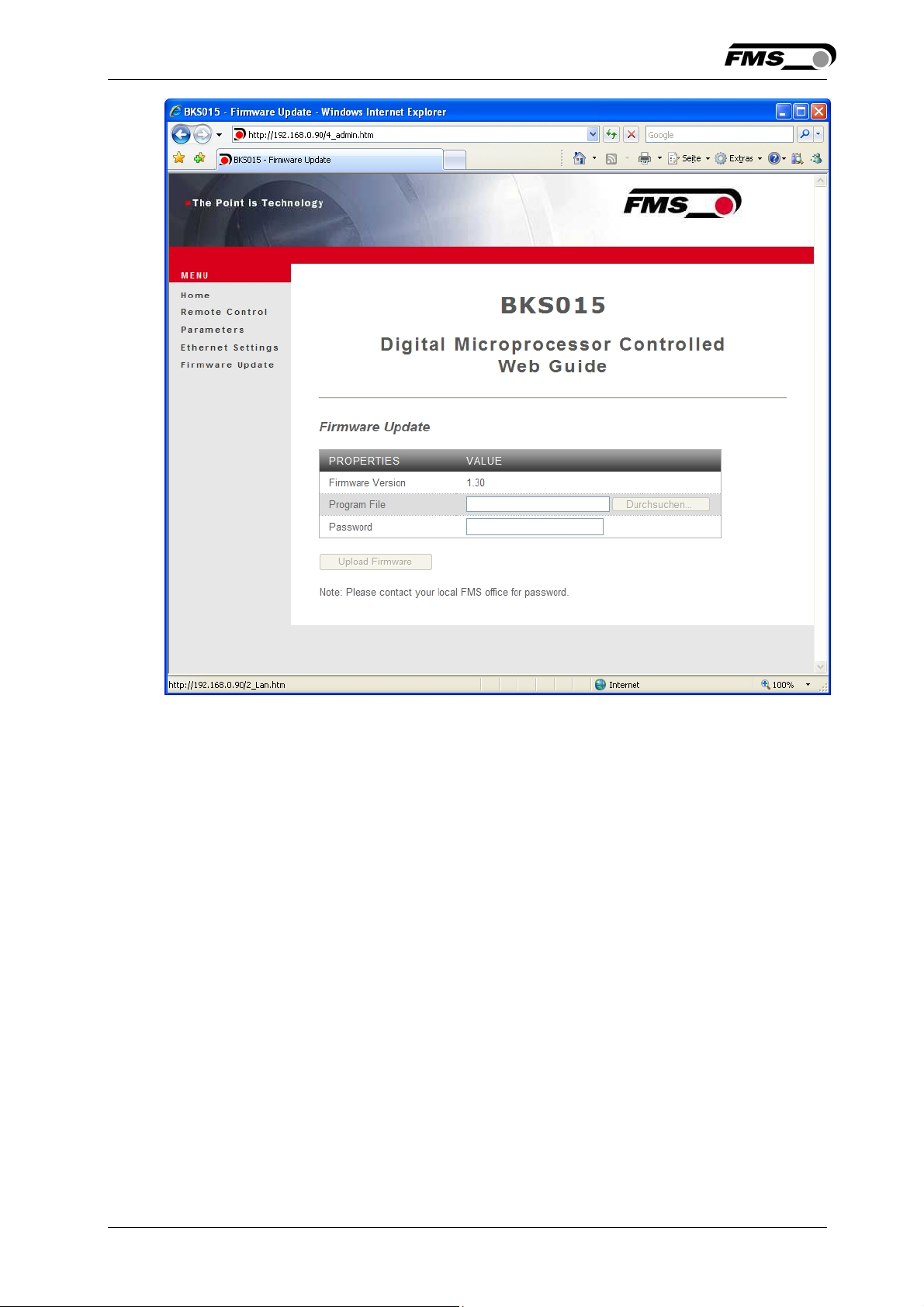
Fig. 20: Firmware update Firware Updates
8.2 Parameterization via a PC (peer-to-peer connection)
This chapter describes the procedure for setting up a desktop or laptop computer to
communicate with FMS BKS015 web guide controller.
Before connecting the FMS BKS015 controller with a “cross-over-cable” directly to a
PC, the computer must be configured with a “static” IP address that lets it recognize
the BKS015. If the BKS015 controller is connected to a network by using e.g. a
switch, the following procedure is not necessary. To establish the connection
between your PC and the BKS015 follow the steps below.
26.11.2018 28
Page 29
Operating Manual BKS015
Setup in Microsoft Windows XP:
1. Click on the Start button (lower left-hand corner of the screen)
2. Click on Control Panel
3. Double click on Local Area Network
4. Right click on the network adapter that is used for the connection.
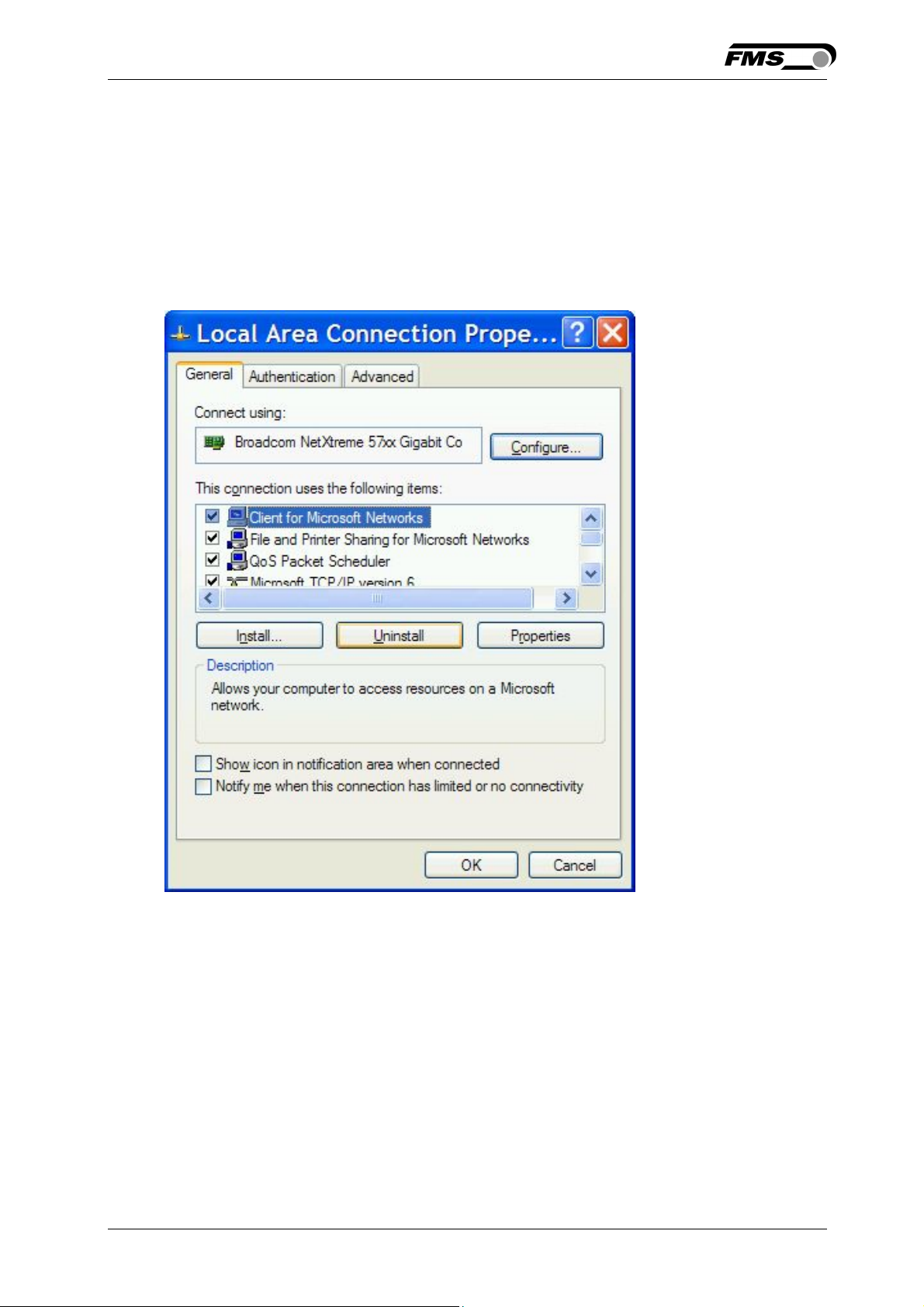
5. Click on Properties on the pop up menu, the following dialog box “Local Area
Connection Properties” will appear.
26.11.2018 29
Page 30
Operating Manual BKS015
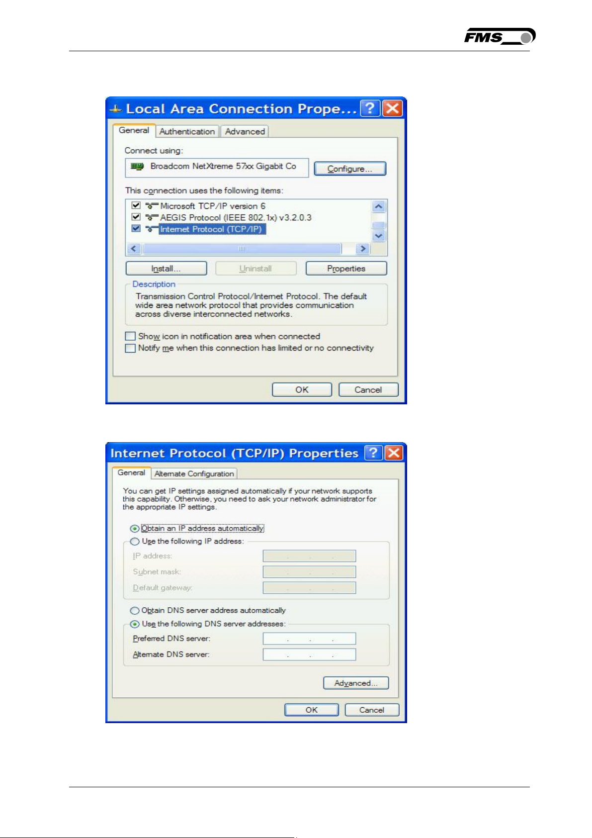
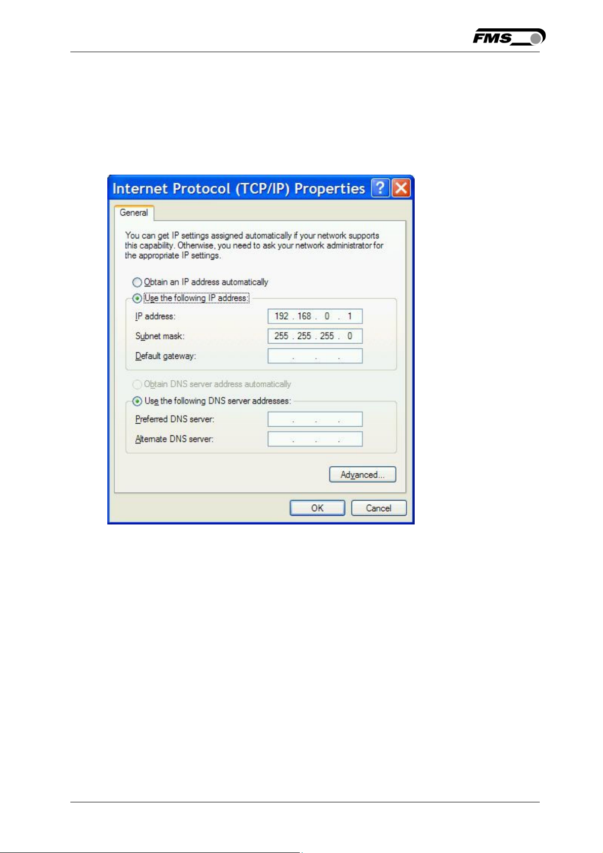
In the box “This connection uses the following items:”, scroll down to “Internet
Protocol (TCP/IP). Select the “Internet Protocol (TCP/IP) and click “Properties” button.
The following dialog box will appear. Make sure the “General” tab is selected.
Select the radio button “Use the following IP address:”
26.11.2018 30
Page 31
Operating Manual BKS015
In the IP address box enter the IP address for the computer that could be
192.168.0.1.
In the Subnet mask, enter 255 255 255 000, as shown below.
Notice that the “000” in both boxes will change automatically to “0”.
The dialog box will change to look like the following:
Click the “OK” button. The following dialog box will appear again:
26.11.2018 31
Page 32

Operating Manual BKS015
Click on the “Close” button.
Close the “Network Connection” window
Close “Control Panel”
The computer is now ready to communicate with the BKS015 controller:
1. Connect the “cross over cable” to both the BKS015 and to the appropriate
port on the desktop or laptop computer (see Fig. 13 and 14).
2. Open Microsoft Internet Explorer or Mizilla Firefox.
3. The default IP address for the BKS015 is 192.168.000.090 as long as it
was not changed over the operating penal. Enter the IP address in the
address bar and hit the Enter key. If a different IP address and subnet mask
is configured at the BKS015 make sure that the computer is setup
appropriate.
4. The screen (Fig.16) will open up. Continue then with the procedure described
in 8.1 “Parametrization in a Network via a Web Browser”.
9 Dimensions
The BKS015 series is available in three different roller length sizes:
• 100mm
• 200mm
26.11.2018 32
Page 33

Operating Manual BKS015
• 250mm
The mechanical dimensions can be seen in the following drawing.
Fig. 21: Outline Drawing BKS015 K015002
26.11.2018 33
Page 34

Operating Manual BKS015
10 Trouble Shooting
Error Cause Corrective action
Edge outside
detection band
Edge has moved
outside the sensor
detection band
BKS guides web
edge immediately
Sensor is mounted on
the wrong side
out of the sensor
Sensor is connected
to the wrong socket
Steering frame
does not move
No signal; sensor not
correctly connected
No signal; cable
interruption
No signal; sensor
defect
No response of
Wiring not correct Check wiring
the interface
LED-row shows
Fuse blown Replace Fuse on power supply board
nothing, frame
doesn’t react
Adjust sensor more accurately to the
web edge;
Adjust reference position less during
automatic operation
Mount sensor to the correct side (right
sensor for „Edge right“, etc.)
Connect sensor plug to the correct
socket (left plug to left socket, etc.)
Connect sensor correctly according to
screw terminal arrangement and
installation guide
Replace cable or send sensor to FMS
Send sensor to FMS; use other sensor
Power supply defect Check or correct power supply
installation
Electronic control unit
Contact FMS customer service
defect
Frame moves
abrupt to one of
the end positions
Stepper motor driver
defective
Exchange actuator of the frame.
Contact FMS service department for
spare parts and installation guide.
26.11.2018 34
Page 35

Operating Manual BKS015
11 Technical Specification
Cycle time 1ms
Drive of steering
frame
Dead band 0…2mm, adjustable in 0.1mm steps
Position reference ±5mm, adjustable in 0.1mm steps
Control modes edge left / edge right / center guiding
Interface Web browser Ethernet Explorer 7 or higher
Operation 3 keys and 5–key wind rose pad
Analogue inputs 2 inputs 0...10V (for sensors)
Supply voltage 24 (18 to 36) VDC
Temperature range -10 ... 60°C (14 to 140°F)
Protection class IP 30
Stepper motor. Power amplifier 24V integrated in housing
26.11.2018 35
Page 36

Operating Manual BKS015
FMS Force Measuring
Systems AG
Aspstrasse 6
8154 Oberglatt (Switzerland)
Tel. 0041 1 852 80 80
Fax 0041 1 850 60 06
info@fms-technology.com
www.fms-technology.com
FMS USA, Inc.
2155 Stonington Avenue
Suite 119
Hoffman Estates,, IL 60169
(USA)
Tel. +1 847 519 4400
Fax +1 847 519 4401
fmsusa@fmstechnology.com
FMS (UK)
Aspstrasse 6
8154 Oberglatt (Switzerland)
Tel. +44 (0)1767 221 303
fmsuk@fms-technology.com
FMS (Italy)
Aspstrasse 6
8154 Oberglatt (Switzerland)
Tel. +39 02 39487035
fmsit@fms-technology.com
26.11.2018 36
 Loading...