

Page 1
2000MM Beaver DHC-2
REALISTIC RIGID
FLAPS INSTALLED STRONG DURABLE EPO
STABLE
SMOOTH FLYING PERFORMANCE
FMSMODEL.COM
Page 2

Page 3
Page 4

Introductions
Contents of Kit
Assembling the Plane
Battery and radio installation
Get your model ready to fly
The transmitter and model setup
Check the control throws
Clevis Installation
Install the propeller and spinner
Center of Gravity(CG)
Before flying the model
Flying course
Trouble shooting
Spare parts list content
ESC instruction
Table of Contents
Introductions
Introducing FMS's latest jewel. The 2000mm Beaver is going to make its official debut!
The largest propeller aircraft offered in the FMS line features all of our latest concepts and technologies. After extensive tests and
product development the Beaver shows excellent performance. While the measured thrust force can reach more than 5000g, the
flying weight is only 3800g.
With a classic combination of black and yellow, the Beaver brings a visual wow factor, as well as impressive performance to the
flying field. Capable of leisurely low/mid-speed flight this model still maintains aerobatic qualities.
With the latest FMS multi-connect technology, we have streamlined the wiring system making it easier to install, eliminating wiring
problems. Easier plane transport is facilitated by the new connectors that allow pilots to remove and replace the wings with just
one step. All channels on each wing are brought together in one port. The pilot can install the main wing simply by inserting the
port and then securing with four screws.
To make flying the Beaver more fun at night, there are 5 LED lights located on the front of the main wing and at the rear of the
fuselage.
The ailerons and flaps are designed to scale. Utilizing the latest EPO52 foam material as well as our new hollow main wing design
greatly alleviates the airplane weight.
Electric Retracts and Floats can be purchased separately to modify your model. Electric Retracts will make your model ready to
tow banners and gliders. The Beaver’s high powered motor is ready to be put to the test for water take off.
Over the years, FMS has been committed to developing different types of products to meet the diverse needs and interests of
pilots. For FMS' first large propeller aircraft, we adopted all of the latest concepts and technologies to bring you a wonderful casual
flight experience.
Features
Multi-connector for easy installation
Lighter EPO 52 foam
Metal landing gear designed for hard landings
Scaled LED night lights
Large tires for any surface
Servo box design for easy assembly & disassembly
Scaled ailerons and flaps
Newly developed lightweight hollow main wing
Oversized battery hatch for 6s battery and 15 minutes of flying time
Optional banner tow and floats upgrades
History
The DHC-2 Beaver is a general purpose bush plane developed by de Havilland Canada. Though originally used for
cargo/passenger hauling and crop dusting, it was also adopted by the United States Armed Forces as a utility aircraft and search
and rescue unit. The single-engined, high-wing, propeller driven STOL aircraft appeared in both the Korean and Vietnam Wars and
was popular amongst front line men. When production finally ceased in 1967, only 1,657 DHC-2 Beavers had been built.
3
··························································································································3
························································································································4
···············································································································5
·····································································································12
·····································································································13
······························································································13
········································································································14
··················································································································15
································································································16
·············································································································16
············································································································17
························································································································18
····················································································································19
···········································································································20
·····················································································································21
Page 5
A.
B.
C.
D.
F.
E.
G.
H.
I.
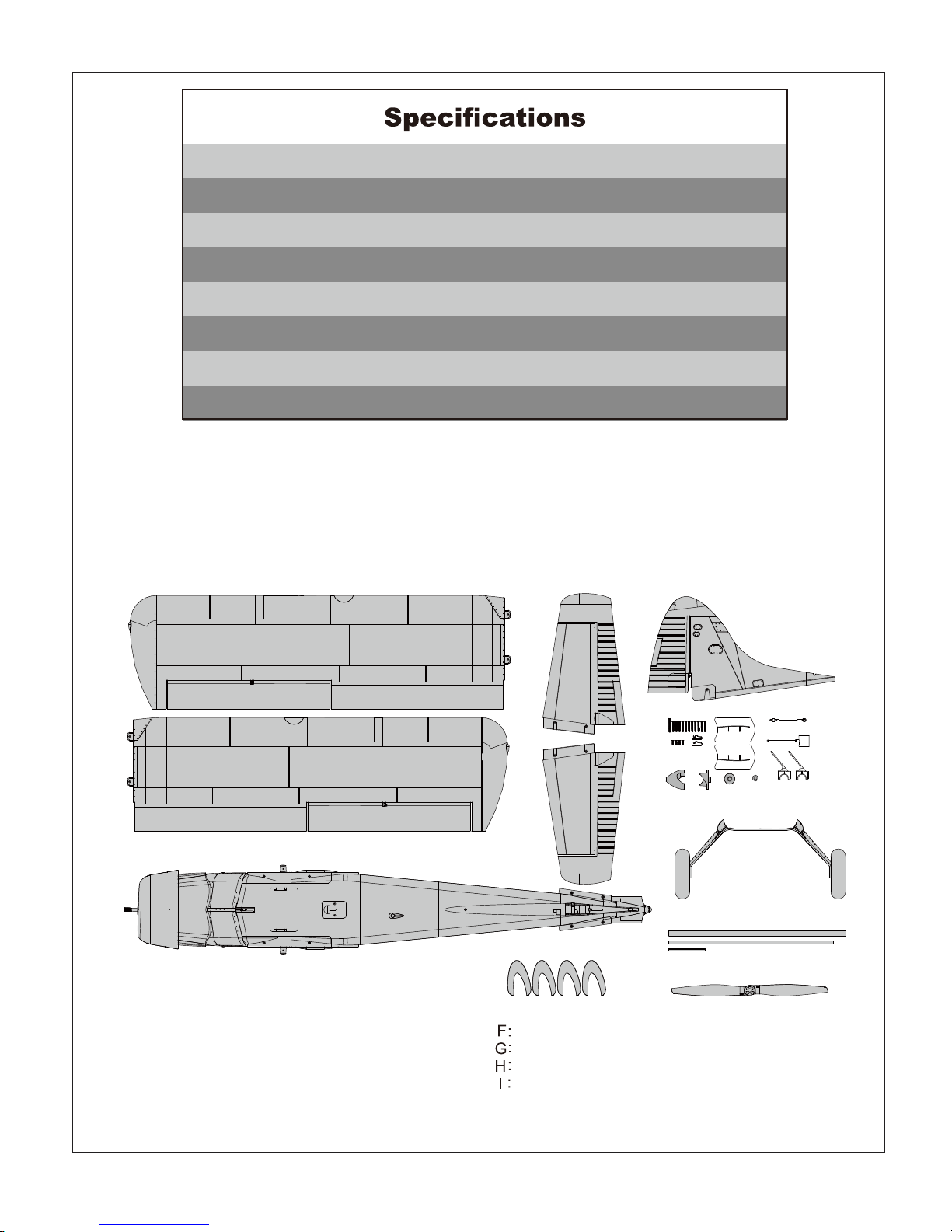
A: Main wing
B: Main fuselage
C: Horizontal stabilizer (Left and Right)
D: Vertical Stabilizer
E: Spinner set and hardware (Screws 4-PA2.6*10MM,
5-HKM3.0*25MM)
Main Landing gear
Tubes
Propeller
Vortex Generator
Before assembly, please inspect the contents of the kit. The photo below details the contents of the kit and
labels. If any parts are missing or defective, please indentify the name or part number (refer to the spare
parts list near the end of the manual) then contact your local shop or email us: [email protected]
Contents of Kit
4
Wingspan: 2000mm (78.7in)
Overall Length: 1304mm (51.3in)
Flying Weight: Around 3800g (134oz)
Motor Size: Brushless 4258-KV550
Wing Load: 71.1 g/dm² (0.16oz/in²)
Wing Area: 53.4 dm² ( sq.in)
ESC: 70A
Servo: 6g Servo x 17
Page 6
5
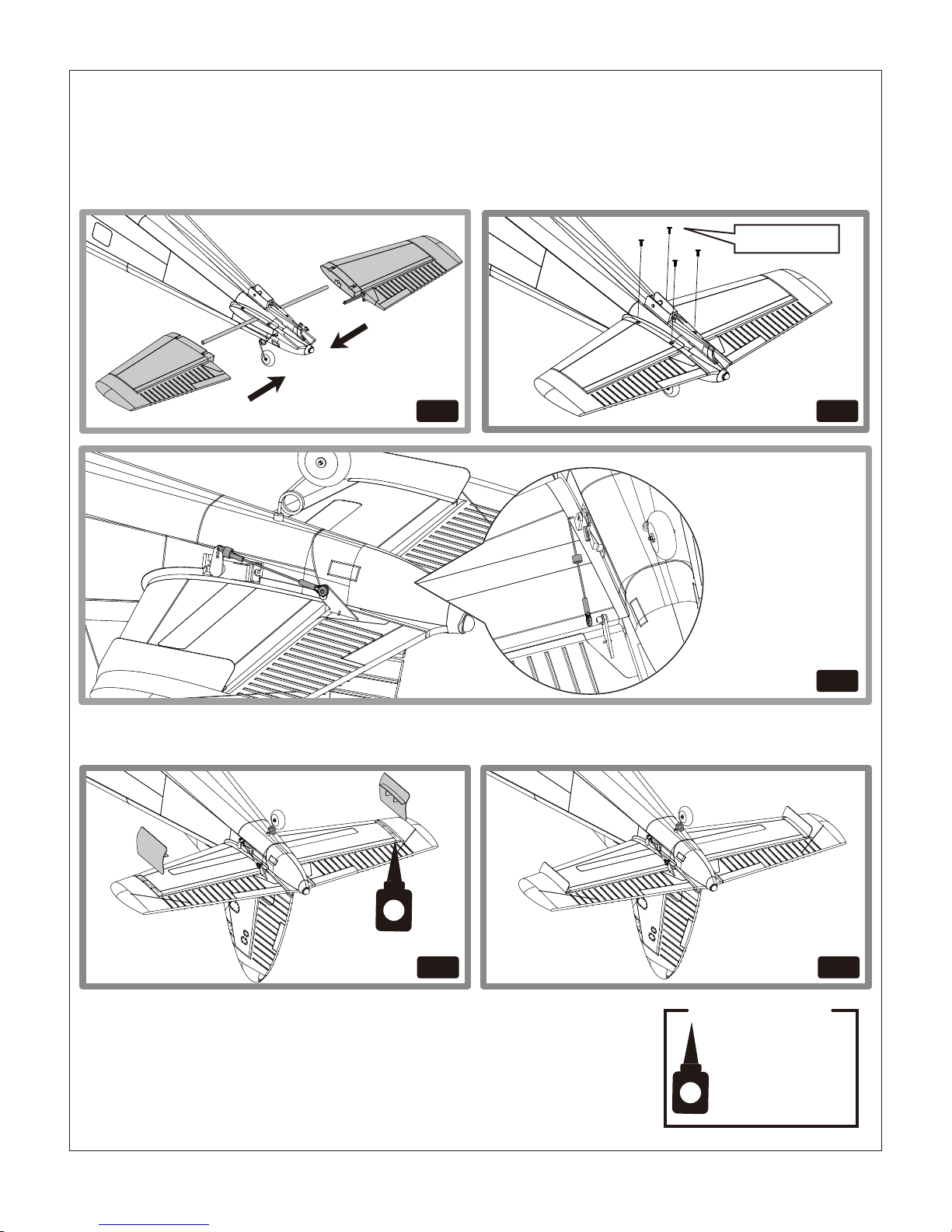
1.Slide the horizontal tail tube into the hole in rear of the fuselage
2.Install the 2 piece(left and right)horizontal tail as shown. Ensure the control horn faces down.
3.Install 4 screws in the front and rear holes in the button of the horizontal tail.
4.Attach the ball link to the elevator control horn’s outermost hole using the included nut and screw.
5. Carefully apply CA to the base and side of the rear Horizontal stabilizer
6. Carefully place the Vortex Generator into the pocket
Horizontal Tail Installation
fig5 fig6
HKM3.0×10mm
fig2
fig1
Required Adhesives:
Foam Safe Medium CA
fig1 fig2
fig3
fig4 fig5
Page 7
6
HKM3.0×26mm
HKM3.0×26mm
HKM3.0×26mm
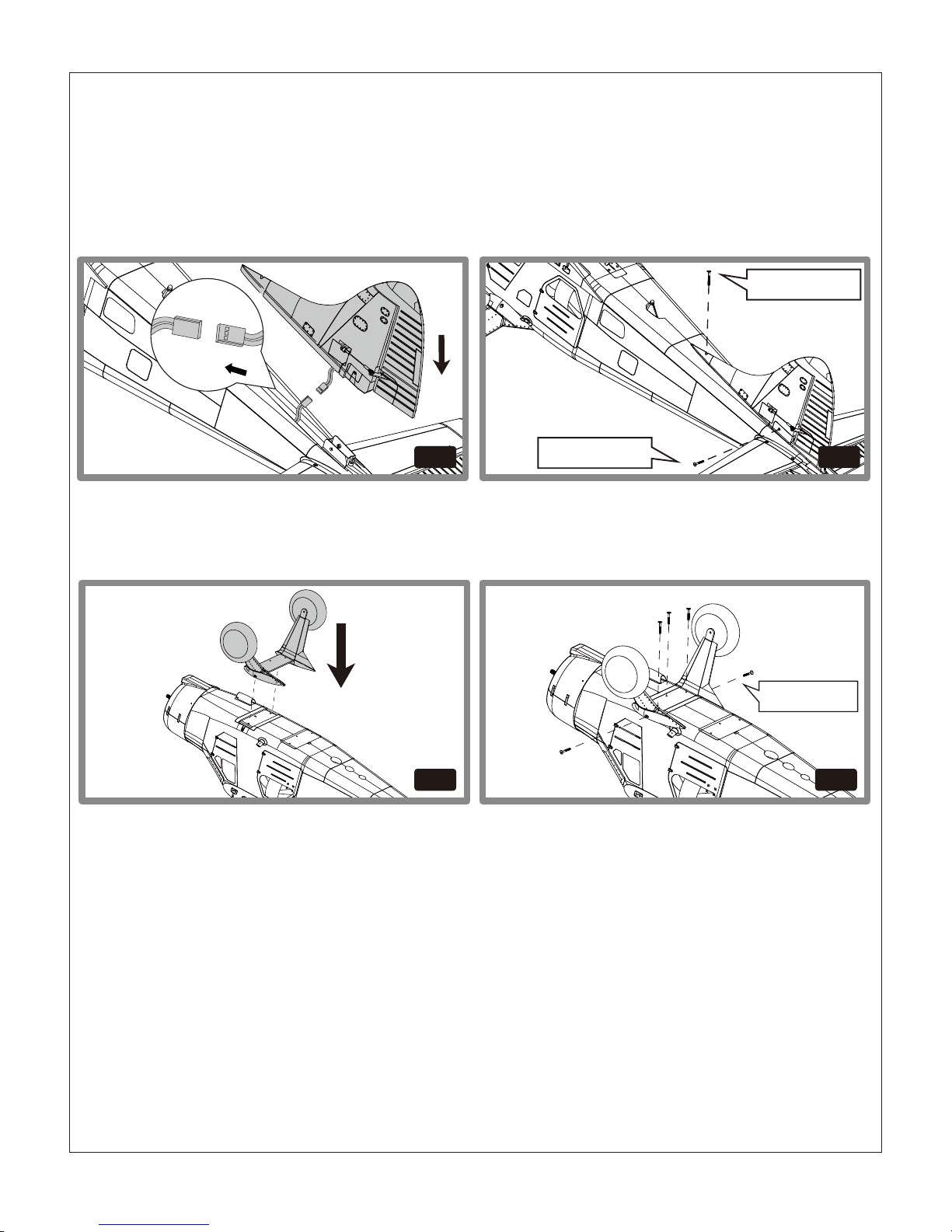
Connect the rudder and elevator servo connectors to the servo extensions in the fuselage.
Slide the vertical tail assembly into the slot in the fuselage.
CAUTION: DO NOT crush or damage the wiring when attaching the vertical tail assembly to the fuselage.
Secure the assembly to the fuselage using 2 screws as shown. Long screw in front hole, shorter screw in rear
hole.
CAUTION:Make sure the screw is tight enough, or it may cause a crash.When needed, disassemble in reverse
order.
Attach the landing gear set on the botton of fuselage. Install three screws in the landing gear flat side and two
screws in both sides.
1.
2.
3.
Vertical Stabilizer Installation
Landing Gear Set Installation
fig6 fig7
fig8 fig9
Page 8
7
fig11
fig13
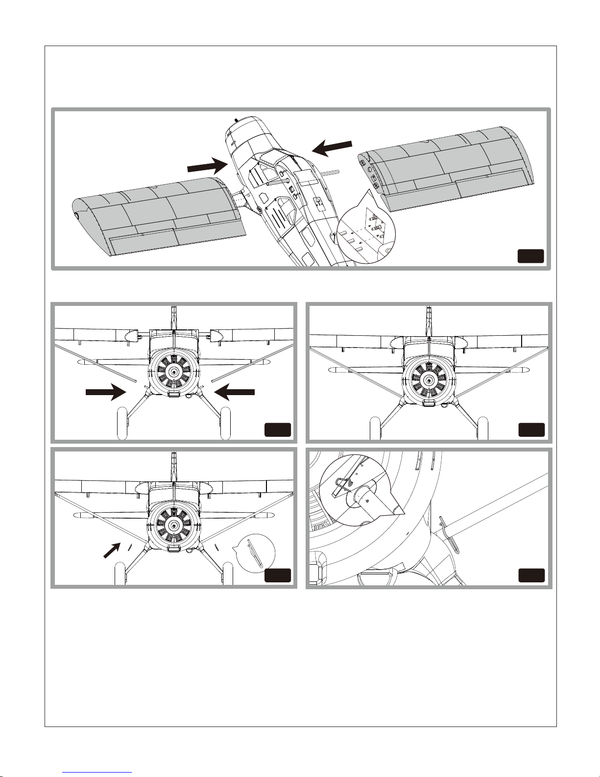
Install the 2 wing struts on the fuselage mount using 2 R-clips. Make sure it is installed precisely.
Slide the tube into the fuselage then install both wings over the wing tube and into the wing slot of the
fuselage.
Notice: The connectors on both side should be attached precisely and firmly.
1.
2.
Wing Installation
fig10
fig12
fig14
fig11
fig13
Page 9
8
HKM3.0×26mm
Removal
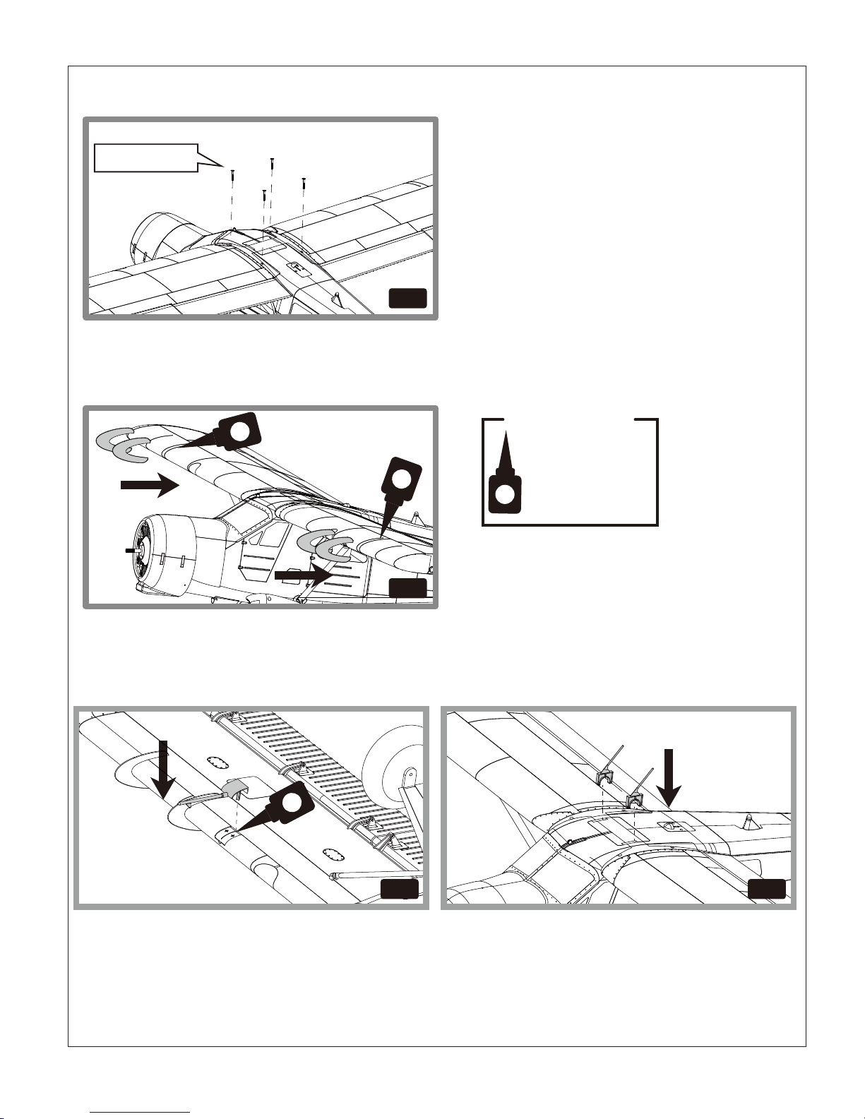
We recommend removing the wings from the fuselage for storage or transport of the aircraft.
1. Carefully apply CA to the base and side of the front main wing
2. Carefully place the Vortex Generator into the pocket
3.Secure the wings on the fuselage using 4 screws in the top of the wings. Make sure it is tightened enough.
Required Adhesives:
Foam Safe Medium CA
1. Carefully apply CA to the base and side of the air speed pocket.
2. Carefully place the Vortex Generator into the pocket.
3. Install the antenna on the top of the fuselage.
fig15
fig16
fig17 fig18
Page 10
9
PA2.6×26mm
KA2.0×10mmPA2.6×26mm
fig20 fig21
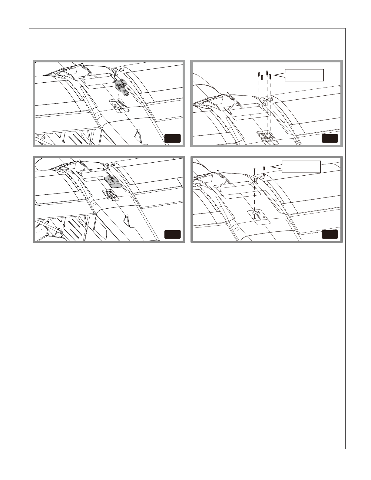
1.Install the retract to the top of fuselage with four screws as photo shows.
2.Install the cover on the retract with two screws.
Optional Towing Retract Installation
fig19 fig20
fig21 fig22
KA2.0×10mm
Page 11
HKM3.0×26mm
HKM3.0×26mm
fig23
1.
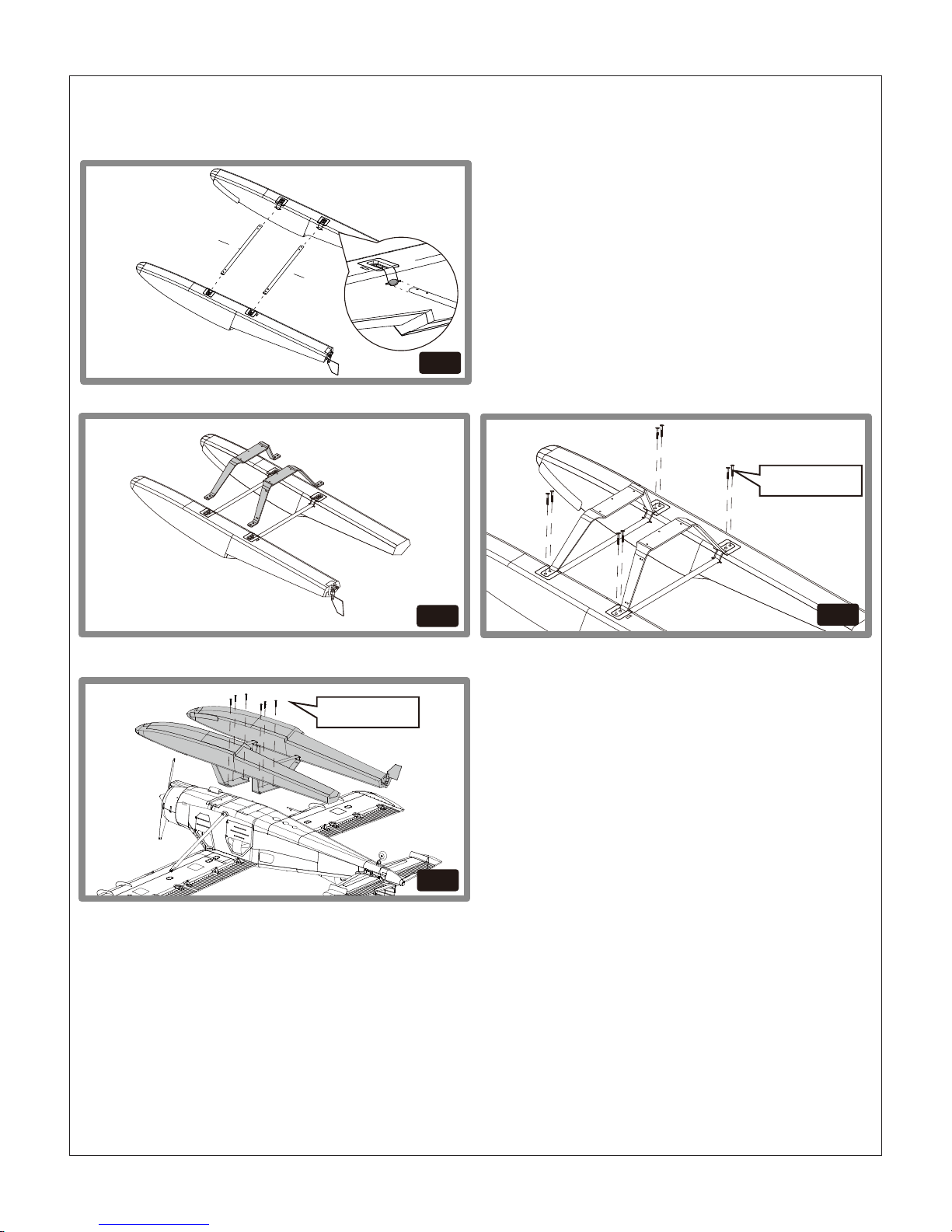
Optional Float Installation
Install the strut bar to both sides of the float. The front bar is longer with 422mm length, the rear bar is shorter
with 412mm length. Wrong installation will cause difficulty landing and taking off (fig.24)
2.Install the float strut to the float with 8 screws as picture shows. (fig26)
3.With the fuselage bottom facing up, carefully install the float set to the fuselage with 6 screws.
422mm
412mm
fig24
10
fig25
fig26
Page 12
11
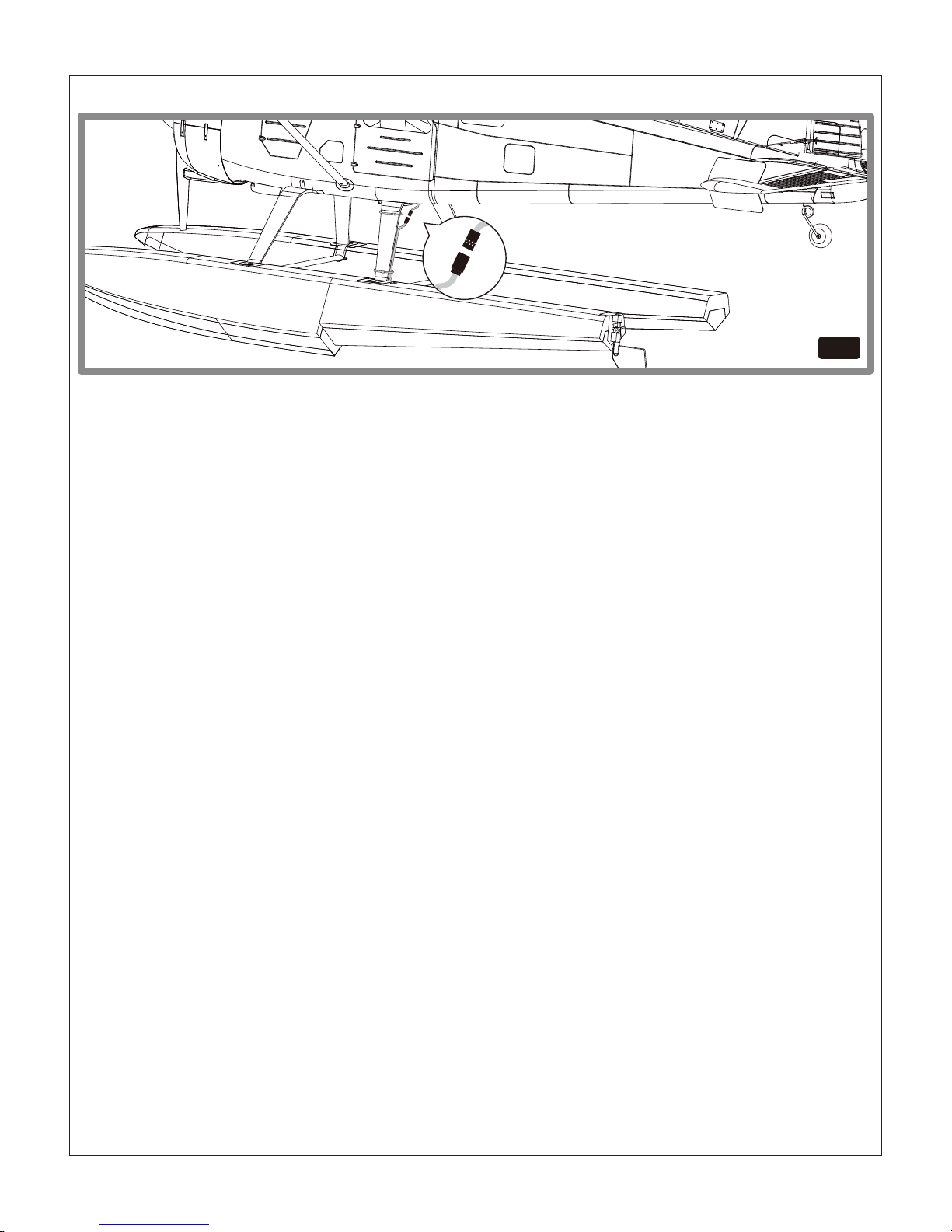
4.Connect the float rudder servo connector then tighten it on the strut with included cable ties.
fig27
Page 13
Float water rudder
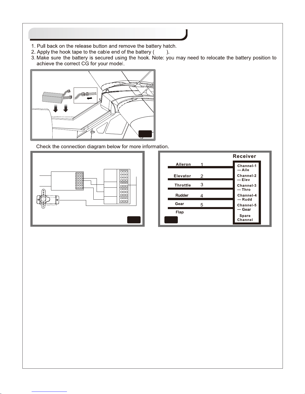
Note:If you have installed the optional retract for towing, use Channel 5 to operate.
12
4.
fig28
fig31
Battery and radio installation
fig30
fig28
R X
AILE
GEAR
RUDD
LED
fig29
Page 14
Get your model ready to fly
Important ESC and model information
The ESC included with the model has a safe start. If the motor battery is connected to the ESC and the
throttle stick is not in the low throttle or off position, the motor will not start until the throttle stick is moved to
the low throttle or off position. Once the throttle stick is moved to the low throttle or off position, the motor will
emit a series of beeps. Several beeps with the same tune means the ESC has detected the cells of the
battery. The count of the beeps equals the cells of the battery. The motor is now armed and will start when
the throttle is moved.
The motor and ESC come pre-connected and the motor rotation should be correct. If for any reason the
motor is rotating in the wrong direction, simply reverse two of the three motor wires to change the direction
of rotation.
The motor has an optional brake setting. The ESC comes with the brake switched off and we recommend
that the model be flown with the brake off. However, the brake could be accidentally switched on if the motor
battery is connected to the ESC while the throttle stick is set at full throttle. To switch the brake off, move the
throttle stick to full throttle and plug in the motor battery. The motor will beep one time. Move the throttle stick
to low throttle or the off position. The motor is ready to run and the brake will be switched off.
Battery Selection and Installation. We recommend the 22.2V 4000mAh 35C Li-Po battery. If using another
battery, the battery must be at least a 22.2V 4000mAh 35C battery. Your battery should be approximately the
same capacity, dimension and weight as the 22.2V 4000mAh 35C Li-Po battery to fit the fuselage without
changing the center of gravity significantly.
The transmitter and model setup
Before getting started, bind your receiver with your transmitter. Please refer to your Transmitter Manual for
proper operation
CAUTION: To prevent personal injury, DO NOT install the propeller assembly onto the motor shaft while
testing the control surfaces. DO NOT arm the ESC and do not turn on the transmitter until the Transmitter
Manual instructs you to do so.
Tips: Make sure all control sticks on your radio are in the neutral position (rudder, elevator, ailerons) and the
throttle is in the OFF position. Make sure both ailerons move up and down (travel) the same amount. This
model tracks well when the left and right ailerons travel the same amount in response to the control stick.
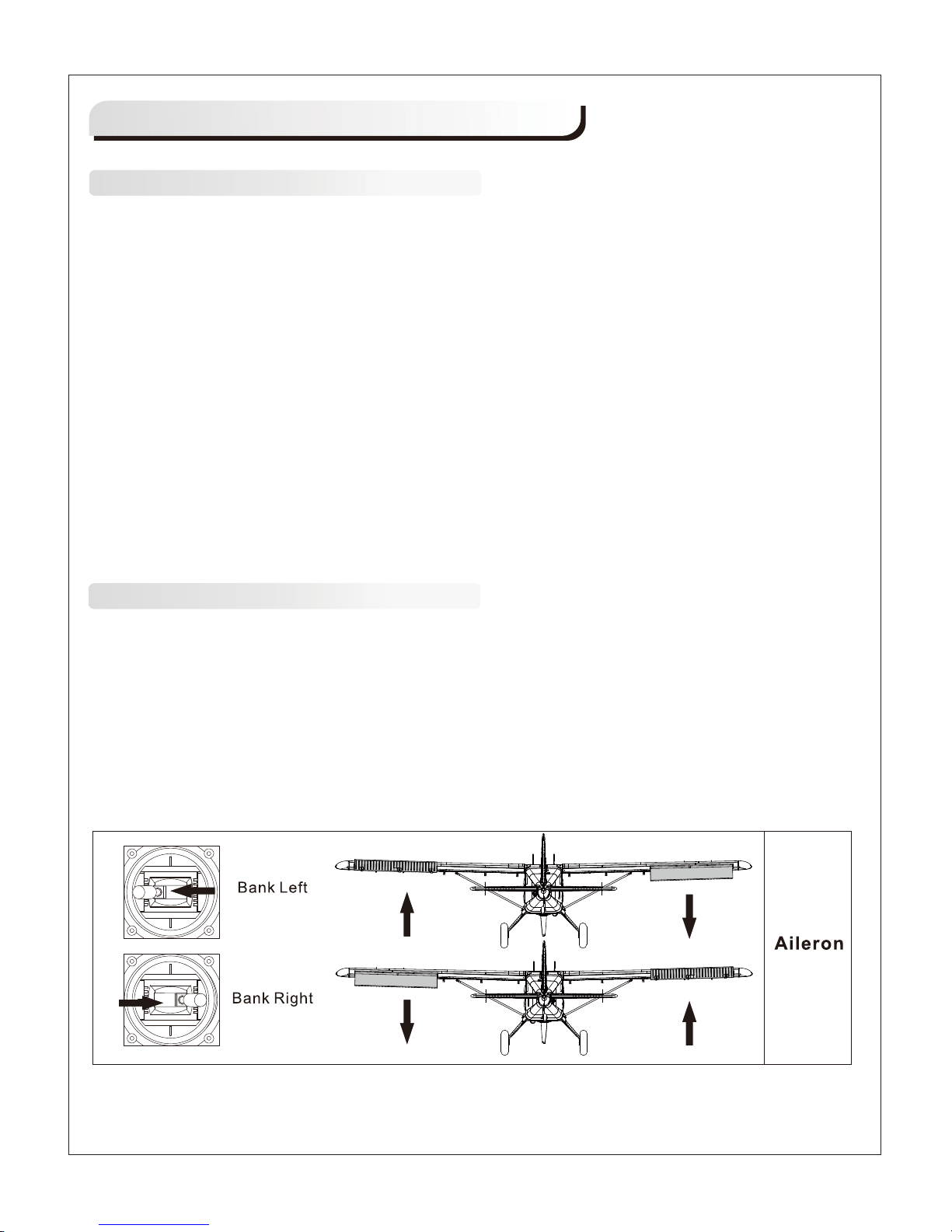
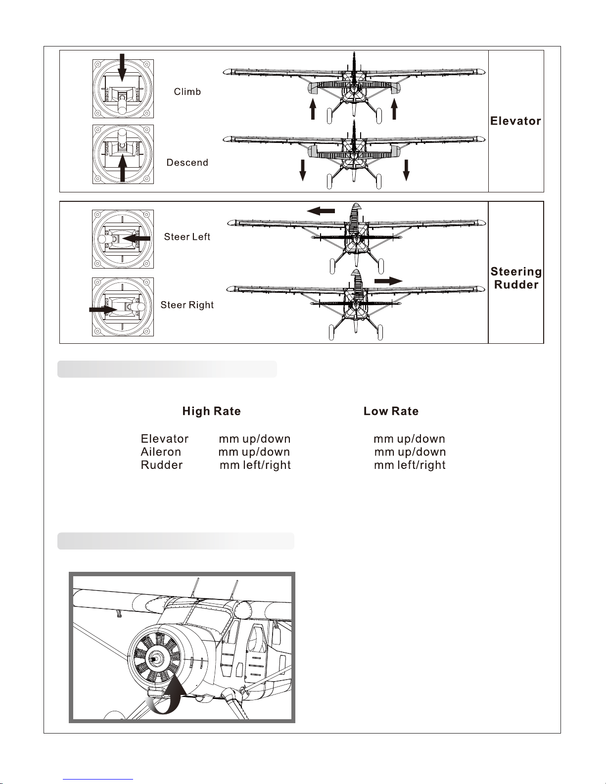
1. Move the controls on the transmitter to make sure the aircraft control surface moves correctly. See
diagrams below.
13
1.
2.
3.
4.
Page 15
14
Check the control throws
Check the motor rotating direction
The motor should rotate clockwise when viewing the plane from the rear.
The suggested control throw setting for FMS MODEL are as follows (dual rate setting):
Tips: On first flight, fly the model in low rate. The first time you use high rates, be sure to fly at low to medium
speeds. High rate, as listed, is only for EXTREME maneuvering.
16
24
16
12
20
10
Page 16
15
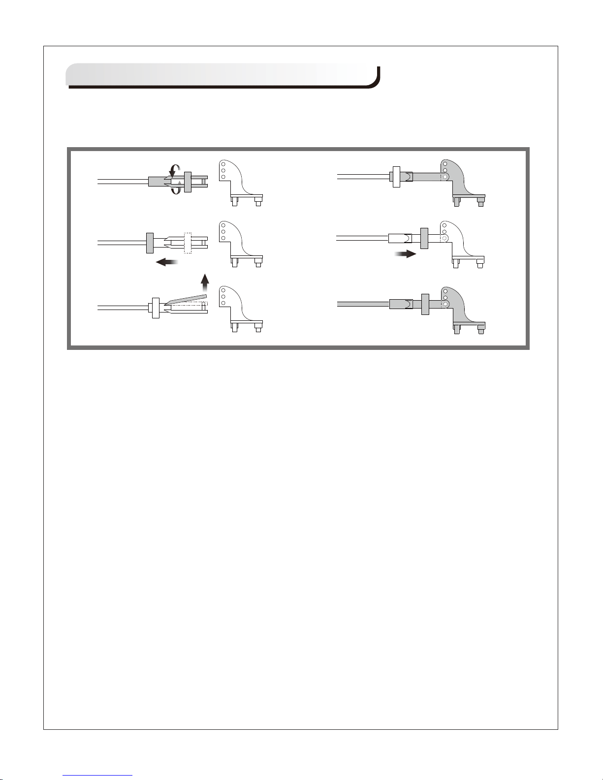
a. Pull the tube from the clevis to the linkage.
b. Carefully spread the clevis, then insert the clevis pin into the desired hole in the control horn.
c. Move the tube to hold the clevis on the control horn.
a.
b.
c.
d.
e.
f.
Clevis Installation
Page 17
16
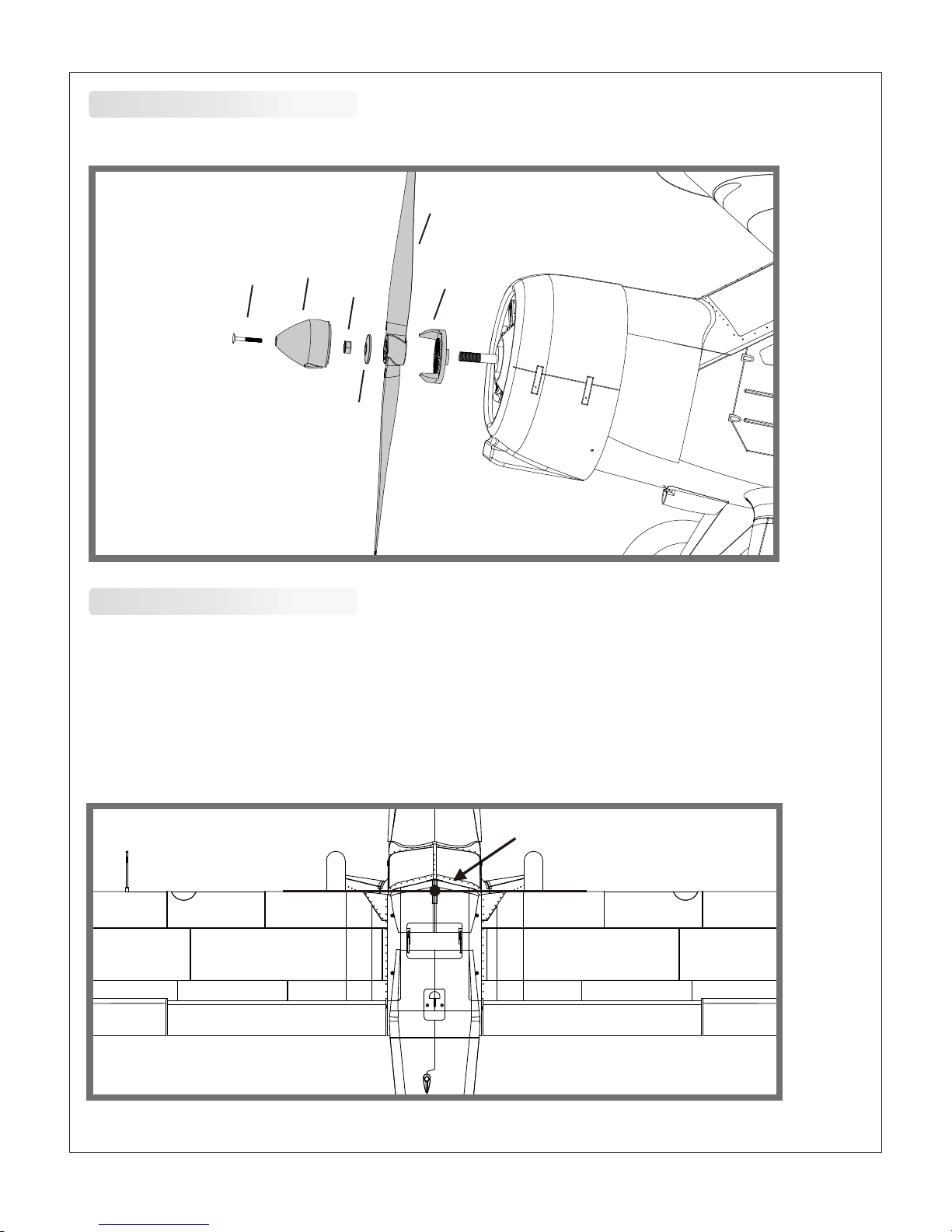
Assemble the spinner and propeller as shown below.
Install the propeller and spinner
Check the C.G. (Center of Gravity)
When balancing your model, adjust the motor battery as necessary so the model is level or slightly nose down.
This is the correct balance point for your model. After the first flights, the CG position can be adjusted for your
personal preference.
1. The recommended Center of Gravity (CG) location for your model is (70-75mm) forward from the leading
edge of the main wing (as shown) with the battery pack installed. Mark the location of the CG on top of the
wing.
2. When balancing your model, support the plane at the marks made on the bottom of the main wing with your
fingers or a commercially available balancing stand. This is the correct balance point for your model. Make sure
the model is assembled and ready for flight before balancing.
a
b
c
d
e
f
70-75mm
Page 18

17
Before flying the model
Find a suitable flying site
Perform the range check for your plane
Monitor your flight time
Find a flying site clear of buildings, trees, power lines and other obstructions. Until you know how much area
will be required and have mastered flying your plane in confined spaces, choose a site which is at least the
size of two to three football fields - a flying field specifically for R/C planes is best. Never fly near people especially children, who can wander unpredictably.
As a precaution, an operational ground range test should be performed before the first flight each time you go
out. Performing a range test is a good way to detect problems that could cause loss of control such as low
batteries, defective or damaged radio components, or radio interference. This usually requires an assistant
and should be done at the actual flying site you will be using.
First turn on the transmitter, then install a fully-charged battery into the fuselage. Connect the battery and
install the hatch.
Remember, use care not to bump the throttle stick. Otherwise, the propeller/fan will turn and possibly cause
damage or injury.
Note: Please refer to your Transmitter Manual that came with your radio control system to perform a ground
range check. If the controls are not working correctly or if anything seems wrong, do not fly the model until
you correct the problem. Make certain all the servo wires are securely connected to the receiver and the
transmitter batteries have a good connection.
Monitor and limit your flight time using a timer (such as on a wristwatch or in your transmitter if available).
When the batteries are getting low you will usually notice a performance drop before the ESC cuts off motor
power, so when the plane starts flying slower you should land. Often (but not always) power can be briefly
restored after the motor cuts off by holding the throttle stick all the way down for a few seconds.
To avoid an unexpected dead-stick landing on your first flight, set your timer to a conservative 4 minutes.
When your alarm sounds you should land right away.
Page 19

18
Flying course
Flying
Take off
While applying power, slowly steer to keep the model straight. The model should accelerate quickly. As the
model gains flight speed you will want to climb at a steady and even rate. The Beaver will climb out at a nice
angle of attack (AOA).
Always choose a wide-open space for flying your plane. It is ideal for you to fly at a sanctioned flying field. If
you are not flying at an approved site always avoid flying near houses, trees, wires and buildings. You should
also be careful to avoid flying in areas where there are many people, such as busy parks, schoolyards, or
soccer fields. Consult laws and ordinances before choosing a location to fly your aircraft. After takeoff, gain
some altitude. Climb to a safe height before trying technical manoeuvres, including high speed passes,
inverted flight, loops, and point rolls.
Land the model when you hear the motor pulsing (LVC) or if you notice a reduction in power. If using a transmitter
with a timer, set the timer so you have enough flight time to make several landing approaches.
Recharge the battery and repair the model as needed .The model’s three point landing gear allows the model
to land on hard surfaces. Align model directly into the wind and fly down to the ground. Fly the airplane down
to the ground using 1/4-1/3 throttle to keep enough energy for proper flare. Before the model touches down,
always fully decrease the throttle to avoid damaging the propeller or other components. The key to a great
landing is to manage the power and elevator all the way to the ground and set down lightly on the main landing
gear. After a few flights you will find the model can be set down lightly on the mains and you can hold the nose
wheel off balancing the model on the mains until it slows and gently settles the nose.
Repairs to the foam should be made with foam safe adhesives such as hot glue, foam safe CA, and 5min
epoxy. When parts are not repairable, see the Spare Parts List for ordering by item number.
Always check to make sure all screws on the aircraft are tightened. Pay special attention to make sure the
spinner is firmly in place before every flight.
Maintenance
Landing
Page 20
19
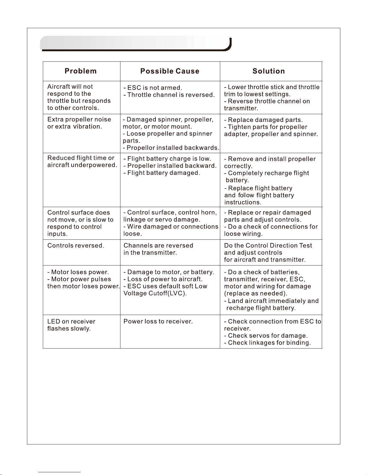
Troubleshooting
Page 21

20
FMSPQ101
FMSPQ102
FMSPQ103
FMSPQ104
FMSPQ105
FMSPQ106
FMSPQ107
FMSPQ108
FMSPQ109
FMSPQ110
FMSPQ111
FMSPQ112
FMSPQ113
FMSPQ114
FMSPQ115
FMSPQ116
FMSPQ117
FMSPQ118
FMSPQ119
FMSFLT002
FMSFLT003
FMSPROP035
FMSBM029
FMSDJ014
FMSDZ005
FMSKV550
PRESC003
FMSSER17MGD
FMSCON003
FMSRE015
Fuselage
Main Wing Set
Horizontal Stabilizer
Vertical Stabilizer
Battery Hatch
Antenna Foam Cover
Cowl
Spinner
Engine
Vortex Generator
Airspeed Head Set
Antenna
Servo Cover
Main Landing Gear Set
Wing Strut Set
Linkage Rod
Screws Set
Pipe
Decal Sheet
Float Set
Float Strut Set
Propeller
Motor Board
Motor Mount
Motor Shaft
Brushless Motor
70A ESC
17g digital metal gear servo
Multi Connector System
Retract
Visit our website to see photos of this product: www.fmsmodel.com
Spare parts list content
Page 22
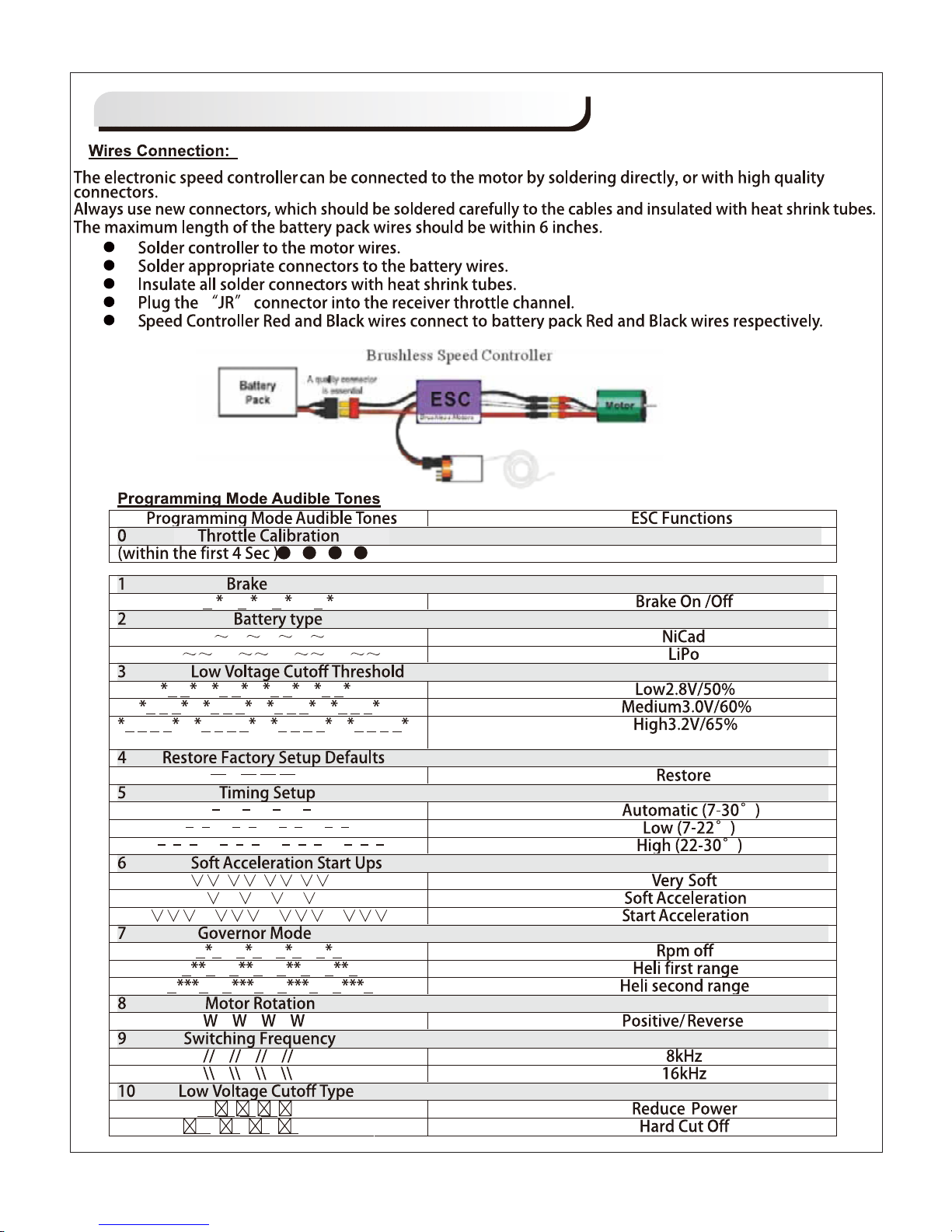
21
ESC instruction
Page 23

Page 24

 Loading...