

Page 1
Wall Mantel and Base with Trim
ASSEMBLY AND INSTALLATION INSTRUCTIONS
Firebox
Perimeter
Trim Included
With This
Mantel
WS26DS, W32DS and W36DS
IMPORTANT: Read entire instruction sheet before
assembling or installing mantel kit.
These mantels are only approved for use with any
DESA Heating Products compact replace system.
Do not use mantel with any other product.
This mantel kit contains the following:
• Mantel pieces - unassembled and marked as follows:
Base #1 Left Side #4 with arrow
Right Side #2 with arrow Left Front Leg #5 with arrow
Right Front Leg #3 with arrow Header #6 with arrow
Top #7
• Hardware Package (117197-01)
• Bracket Hardware Kit (118983-01)
• Trim Kit 113140-02 (26"), 113140-01 (32") or
113140-14 (36")
• Trim Kit Hardware (102866-01)
The hardware kit 117197-01 contains the following:
• 28 - 1 1⁄4" Screws
• 2 - 3" Screws
Tools required:
• #2 Phillips drill bit (3 1/2" min. length)
• Slotted screw driver • Drill Driver
• Measuring Tape • Pencil
If any wood pieces are missing or damaged, contact the
dealer where you purchased this mantel for replacement.
If hardware or trim is missing or damaged, contact DESA
Heating Products at 1-866-672-6040 for referral information. You can also visit DESA Heating Products' technical service
web site at www.desatech.com.
Note: Gather all mantel pieces together before assembling
mantel.
WARNING: Only use 1 1/4" screws in pocket holes to
assemble mantel. Damage to mantel will result if other
screws are used for this purpose.
WARNING: Use only 1/2" or 3/4" screws with brackets in hardware pack 118983-01. Damage to mantel will
result if other screws are used for this purpose.
ASSEMBLING MANTEL
IMPORTANT: More than one person is required to lift
assembled mantel. Lift mantel by leg assemblies. Lifting
by header or mantel top could damage mantel.
1. For leg assembly, lay side or front that does not contain
pocket holes front side down on a soft surface. Pocket
hole locations will vary by model. Pay special attention
to the up direction arrows on panels.
2. Position second panel as shown in Figure 1, page 2. Align
panels at bottom. With one person holding the panel alignment secure, attach panels using 1 1/4" screws through
pocket holes. Check assembly for correct alignment.
3. Repeat steps 1 and 2 for second leg assembly.
4. Each leg assembly will use 3 brackets for stability. Your
bracket hardware kit will contain either 1/2" or 3/4" screws.
Using two 1/2" or 3/4" screws, install a bracket in the center
of each leg assembly and one at each end within 1" of but
not over the last pocket hole (see Figure 2, page 2).
www.desatech.com
Page 2
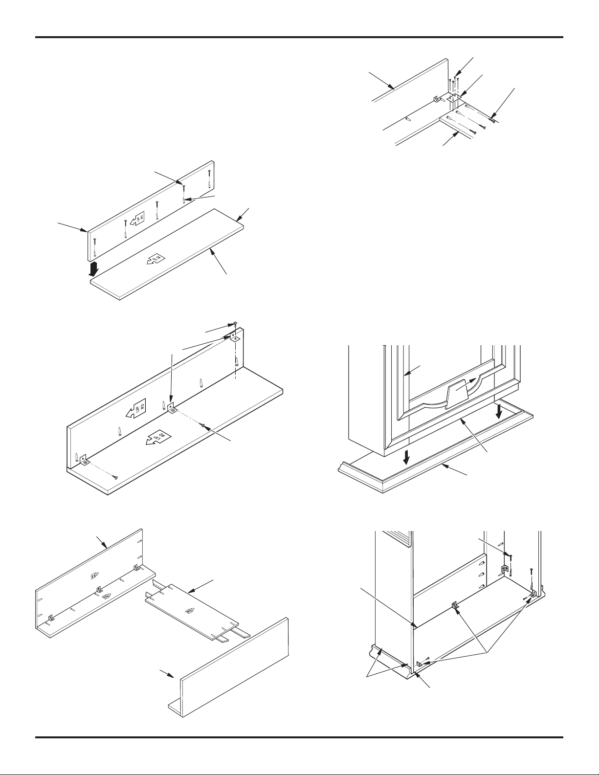
5. Position header between leg assemblies with direction
arrow pointing up (see Figure 3). Attach header to leg
assemblies through predrilled holes with 1 1⁄4" screws
in each leg assembly as shown in Figure 4. You may
prefer to lay mantel face down on a soft surface instead
of upright. Using pocket holes and 11/4" screws, attach
header to leg assemblies. Be sure you have proper align-
ment between the header and leg assemblies. Attach at
brackets with 1/2" or 3/4" screws using 1 at bracket and
4 screws per side (see Figure 4).
1 1/4" Screw for
Pocket Holes
Leg
Front
Figure 1 - Assembling Legs
1/2" or 3/4" Screws
Brackets
Pocket
Holes
Leg Side
Bottom of
Panel
Left Side Leg
Assembly
Header
Figure 4 - Attaching Header to Leg Assembly
1/2" or 3/4" Screws
Flat Bracket
1 1/4" Screw
ATTACHING TOP OF MANTEL
Turn top (#7) and leg assembly upside down on soft surface.
1.
Place header/leg assembly inside top (see Figure 5).
2. Make sure mantel is centered left to right inside top and
rear of legs are ush with back of top. Gap between mantel
top and leg should be the same from front to back (see
Figure 5).
3. Attach side and header assembly to mantel top using 1
1
⁄4" screws inserted through pocket holes (see Figure 6).
4. Attach 3 brackets to assembly using two 1/2" or 3/4" screws
per bracket. One bracket should be in center of header
and the other two toward back of leg assembly on each
side (see Figure 6).
5. With assistance, carefully turn assembly upright.
Leg
Assembly
Right Side Leg
Assembly
Figure 2 - Attaching Brackets
Top of
Mantel
Header
Left Side Leg
Assembly
Figure 3 - Installing Header
Screw
Header
Top
Figure 5 - Placing Mantel Assembly onto Mantel Top
Screws
Small
Gap
Make certain
spacing is the
same front and
back.
Figure 6 - Attaching Top to Leg and Header Assembly
Legs Should Be
Flush With Top
Bracket with 1/2"
or 3/4" Screw
2
www.desatech.com
119360-01B
Page 3

ASSEMBLING TRIM
1. Remove packaging from three pieces of trim.
2. Locate two adjusting plates with set screws, and two
shims in the hardware packet.
3. Align shim under adjusting plate as shown in Figure 7.
4. Slide one end of adjusting plate/shim in slot on mitered
edge of top trim (see Figure 7).
5. Slide other end of adjusting plate/shim in slot on mitered
edge of side trim (see Figure 7).
6. While rmly holding edges of trim together, tighten both
set screws on the adjusting plate with slotted screwdriver.
7. Repeat steps 2 through 6 for other corner.
Set Screws
Adjusting
Plate
Slot
Top Trim
Mitered Edge
4. Attach mantel to base using 1 1/4" screws through pocket
holes. Using brackets and 1/2" or 3/4" screws from
bracket hardware kit, attach brackets to base and mantel
assembly using one bracket at each back corner of leg
sides and one on each leg front (see Figure 9).
5. Adjust replace so that it ts into mantel opening properly.
(Side view
for clarity)
Shoulder
Screw
Shim
Slot
Figure 7 - Assembling Trim
Side Trim
FIREPLACE INSTALLATION
1. Fireplace should be fully assembled. See Assembling
Fireplace in replace owner’s manual.
2. Place mantel base close to installation location. See re-
place owner’s manual for installation clearances. Leave
enough room to get behind mantel once replace and
mantel assembly have been attached to base if installing
a replace with ange.
3. Install gas line. See Connecting to Gas Supply in replace
owner’s manual. Remember to leave access to the gas
shutoff valve somewhere on the base or where it is accessible to the user.
4. Check for leaks. See Checking Gas Connections in re-
place owner’s manual.
IMPORTANT: If your replace has a nailing ange see Installing
Fireplace with Flange. If your replace does not have a nailing
ange see Installing Fireplace without Flange, page 4.
Installing Fireplace with Flange
1. Place mantel assembly on wood base and center left to
right having back of assembly ush with back of base.
Mark placement on base along inside front of mantel
assembly. Remove mantel assembly from base.
2. Position replace on base centering left to right between
markings. Carefully position gas lines. IMPORTANT: Use
caution when positioning replace on base as base may
scratch.
3. With assistance, carefully place mantel over replace
(see Figure 8). Fireplace nailing anges will be to inside
of mantel. Align mantel with markings made previously.
Make sure back of mantel is ush with back of mantel
base. Adjust replace as necessary.
Assembled
Trim
Shoulder
Screws
Figure 8 - Installing Fireplace with Flange
Figure 9 - Installing Brackets to Mantel Base
Possible
Shutoff Valve
Mantel
Base
Locations
11/4" Screw
Bracket with 1/2"
or 3/4" Screw
Gas Line
Access Hole
119360-01B
www.desatech.com
3
Page 4

119360 01
6. Fireplace with louver door: Lower bottom louver door. Use
O
F
F
P
I
L
O
T
O
N
H
I
L
O
two screws provided in hardware package and attach replace to wooden base (see Figure 10). Close louver door
Fireplace with xed louver: Before installing logs or burner
assembly (see owner’s manual) remove screws securing
oor to assembly. Lift oor for access to bottom of replace.
Use two screws provided in replace hardware package
and attach replace base to wooden base (see Figure 11).
Reinstall oor with screws removed previously.
7. Place metal trim on shoulder screws. Firmly snap trim
assembly over shoulder screws on replace.
8. Carefully push mantel and base into position against
wall.
Bottom
Louver Door
Hole for Attaching
Fireplace System to
Wooden Mantel Base
Installing Fireplace without Flange
1. Place mantel assembly on wood base and center left to
right having back of assembly ush with back of base.
2. Attach mantel to base using 1 1/4" screws through pocket
holes. Using brackets and 1/2" or 3/4" screws from
bracket hardware kit, attach brackets to base and mantel
assembly using one bracket at each back corner of leg
sides and one on each leg front (see Figure 9, page 3).
3. Position replace inside mantel (see Figure 12). Carefully position gas lines. IMPORTANT: Use caution when
positioning replace on base. Base may scratch easily.
4. Fireplace with louver door: Lower bottom louver door. Use
two screws provided in hardware package and attach
replace to wooden base (see Figure 10). Close louver
door
Fireplace with xed louver: Before installing logs or burner
assembly (see owner’s manual) remove screws securing oor to assembly. Lift oor for access to bottom of
replace. Use two screws provided in replace hardware
package and attach replace base to wooden base (see
Figure 11). Reinstall oor with screws removed previ-
ously.
5. Place metal trim on shoulder screws. Firmly snap trim
assembly over shoulder screws on replace.
6. Carefully push mantel and base into position against
wall.
Figure 10 - Attaching Fireplace to Mantel and Mantel Base
Screws
Fixed
Louver
Holes are Behind Louver on
Fireplace Bottom for Attaching
Fireplace to Wooden Mantel
Base.
Figure 11 - Screw Locations for Fireplaces with Fixed Louver
(Side view
for clarity)
Shoulder Screw
Assembled
Metal Trim
Figure 12 - Installing Fireplace without Flange
Shoulder
Screws
Mantel
Base
Possible
Shutoff
Valve
Locations
2701 Industrial Drive
P.O. Box 90004
Bowling Green, KY 42102-9004
Technical Service and Parts
1-866-672-6040
NOT A UPC
119360-01
Rev. B
07/06
 Loading...