

FMI VSGF33PRC, VSGF33NRC Owner's Manual
UNVENTED (VENT-FREE) GAS FIREPLACE
PFS
US
OWNER’S OPERATION AND INSTALLATION MANUAL
®
Shown with optional cabinet mantel with hearth base and trim accessories.
VSGF33PRC AND VSGF33NRC
REMOTE-READY FIREPLACE SYSTEM
WARNING: If the information in this manual is not
followed exactly, a re or explosion may result causing
property damage, personal injury, or loss of life.
— Do not store or use gasoline or other ammable
vapors and liquids in the vicinity of this or any other
appliance.
— WHAT TO DO IF YOU SMELL GAS
• Do not try to light any appliance.
• Do not touch any electrical switch; do not use any
phone in your building.
•
Immediately call your gas supplier from a neighbor’s
phone. Follow the gas supplier’s instructions.
• If you cannot reach your gas supplier, call the re
department.
— Installation and service must be performed by a quali-
ed installer, service agency, or the gas supplier.
INSTALLER: Leave this manual with the appliance.
CONSUMER: Retain this manual for future reference.
For more information, visit www.fmiproducts.com
TABLE OF CONTENTS
Safety .................................................................. 2
Product Identication ........................................... 4
Local Codes......................................................... 5
Unpacking............................................................ 5
Product Features ................................................. 5
Air For Combustion and Ventilation ..................... 6
Installation ........................................................... 8
Operation ........................................................... 18
Inspecting Burners............................................. 21
Cleaning and Maintenance ................................ 22
SAFETY
Wiring Diagram .................................................. 23
Troubleshooting ................................................. 24
Parts .................................................................. 28
Replacement Parts ............................................ 32
Specications .................................................... 32
Service Hints ..................................................... 32
Technical Service............................................... 32
Accessories ....................................................... 33
Warranty ..............................................Back Cover
WARNING: Improper
installation, adjustment,
alteration, service, or
maintenance can cause
injury or property damage. Refer to this manual
for correct installation
and operational procedures. For assistance or
additional information
consult a qualified installer, service agency, or
the gas supplier.
WARNING: This is an
unvented gas-red heater. It uses air (oxygen)
from the room in which
it is installed. Provisions
for adequate combustion
and ventilation air must
be provided. Refer to Air
for Combustion and Ventilation section on page 6
of this manual.
This appliance may be in-
stalled in an aftermarket,*
permanently located,
manufactured (mobile)
home, where not prohibited by local codes.
This appliance is only for
use with the type of gas
indicated on the rating
plate. This appliance is
not convertible for use
with other gases.
* Aftermarket: Completion of sale, not for
purpose of resale, from the manufacturer
WARNING: This product
contains and/or generates
chemicals known to the State
of California to cause cancer or
birth defects, or other reproductive harm.
IMPORTANT: Read this owner’s
manual carefully and completely
before trying to assemble, operate, or service this heater.
Improper use of this heater can
cause serious injury or death
from burns, fire, explosion,
electrical shock, and carbon
monoxide poisoning.
www.fmiproducts.com
119304-01H2

SAFETY
Continued
DANGER: Carbon monoxide
poisoning may lead to death!
Carbon Monoxide Poisoning: Early signs
of carbon monoxide poisoning resemble the
u, with headaches, dizziness, or nausea. If
you have these signs, the heater may not be
working properly. Get fresh air at once! Have
heater serviced. Some people are more affected by carbon monoxide than others. These
include pregnant women, people with heart or
lung disease or anemia, those under the inuence of alcohol, and those at high altitudes.
Natural and Propane/LP Gas: Natural and
propane/LP gases are odorless. An odormaking agent is added to the gas. The odor
helps you detect a gas leak. However, the
odor added to the gas can fade. Gas may be
present even though no odor exists.
Make certain you read and understand all
warnings. Keep this manual for reference. It
is your guide to safe and proper operation of
this heater.
WARNING: Any change to
this heater or its controls can
be dangerous.
WARNING: Do not use a
blower insert, heat exchanger
insert, or other accessory not approved for use with this heater.
WARNING: Do not allow fans
to blow directly into the replace.
Avoid any drafts that alter burner
ame patterns. Ceiling fans can
create drafts that alter burner
ame patterns. Altered burner
patterns can cause sooting.
Due to high temperatures, the
appliance should be located out
of trafc and away from furniture
and draperies.
Do not place clothing or other
ammable material on or near
the appliance. Never place any
objects on the heater.
Fireplace front and screen become very hot when running replace. Keep children and adults
away from hot surfaces to avoid
burns or clothing ignition. Fireplace will remain hot for a time
after shutdown. Allow surfaces
to cool before touching.
Carefully supervise young chil-
dren when they are in the room
with replace. When using the
optional hand-held remote accessory, keep selector switch
in the OFF position to prevent
children from turning on burners
with remote.
You must operate this replace
with the replace screen and
hood in place. Make sure replace screen and hood are in
place before running heater.
Keep the appliance area clear
and free from combustible materials, gasoline, and other ammable vapors and liquids.
1. This appliance is only for use with the type
of gas indicated on the rating plate. This
appliance is not convertible for use with
other gases.
2. Do not place propane/LP supply tank(s)
inside any structure. Locate propane/LP
supply tank(s) outdoors (propane/LP units
only).
119304-01H 3
www.fmiproducts.com
SAFETY
Continued
3. If you smell gas
• shut off gas supply
• do not try to light any appliance
• do not touch any electrical switch; do not
use any phone in your building
• immediately call your gas supplier from
a neighbor’s phone. Follow the gas
supplier’s instructions
• if you cannot reach your gas supplier,
call the re department
4. This replace shall not be installed in a
bedroom or bathroom.
5. Do not use this replace as a wood-burning replace. Use only the logs provided
with the replace.
6. Do not add extra logs or ornaments such
as pine cones, vermiculite, or rock wool.
Using these added items can cause sooting. Do not add lava rock around base.
Rock and debris could fall into the control
area of replace.
7. To prevent the creation of soot, follow the
instructions in Cleaning and Maintenance,
page 22.
8. Before using furniture polish, wax, carpet
cleaner, or similar products, turn heater
off. If heated, the vapors from these products may create a white powder residue
within burner box or on adjacent walls or
furniture.
9. This replace needs fresh air ventilation to
run properly. This replace has an Oxygen
Depletion Sensing (ODS) safety shutoff
system. The ODS shuts down the replace if enough fresh air is not available.
See Air for Combustion and Ventilation,
page 6. If replace keeps shutting off, see
Troubleshooting, page 24.
10. Do not run replace
• where ammable liquids or vapors are
used or stored
• under dusty conditions
11. Do not use this replace to cook food or
burn paper or other objects.
12. Do not use replace if any part has been
exposed to or under water. Immediately
call a qualied service technician to inspect the replace and to replace any part
of the control system and any gas control
which has been under water.
13. Do not operate fireplace if any log is
broken. Do not operate replace if a log
is chipped (dime-sized or larger).
14. Turn fireplace off and let cool before
servicing. Only a qualied service person
should service and repair replace.
15. Operating replace above elevations of
4,500 feet could cause pilot outage.
16. To prevent performance problems in
propane/LP units, do not use propane/LP
fuel tanks of less than 100 lbs. capacity
(propane/LP units only).
17. Provide adequate clearances around air
openings.
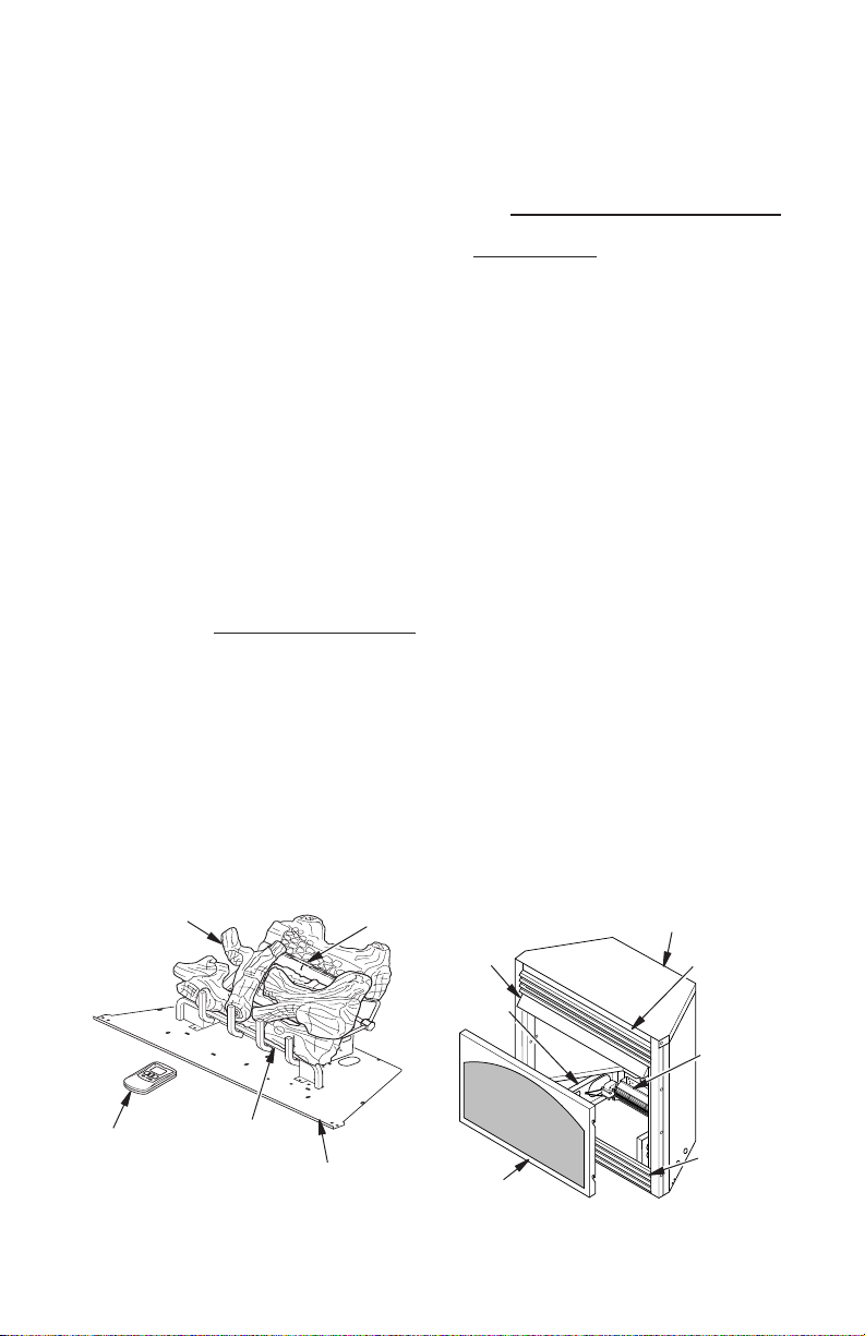
PRODUCT IDENTIFICATION
Log Set
Optional
Remote
Control
Figure 1 - Log Base Assembly
Front
Burner
Rear
Burner
Base
Assembly
www.fmiproducts.com
Fireplace
Hood
Firebox
Support
Screen
Assembly
Top Outer Casing
Top Louver
Assembly
Optional
Blower
Assembly
(Not
Included)
Bottom
Louver
Assembly
Figure 2 - Fireplace
119304-01H4
LOCAL CODES
Install and use replace with care. Follow all
local codes. In the absence of local codes,
use the latest edition of The National Fuel
Gas Code ANSI Z223.1/NFPA 54*.
*Available from:
American National Standards Institute, Inc.
1430 Broadway
New York, NY 10018
National Fire Protection Association, Inc.
Batterymarch Park
Quincy, MA 02269
Note: Where listed vented decorative logs
are required, thermostat operation is not
permitted.
UNPACKING
CAUTION: Do not remove the
data plates attached to the heater
base assembly. The data plates
contain important warranty and
safety information.
1. With utility knife, cut the carton all the way
around above the staples on the bottom
tray. Lift the carton off the heater. Remove
packing.
Note: The hood is located in the packing
on the right hand side of the heater front.
Lift the heater off the bottom tray.
State of Massachusetts: The installation
must be made by a licensed plumber or
gas tter in the Commonwealth of Massachusetts.
Sellers of unvented propane or natural
gas-red supplemental room heaters shall
provide to each purchaser a copy of 527
CMR 30 upon sale of the unit.
Vent-free gas products are prohibited for
bedroom and bathroom installation in the
Commonwealth of Massachusetts.
2. Locate two screws above top corners of
the replace screen. Remove and discard
these screws. Lift replace screen up and
pull out to remove.
3. Remove protective packaging applied to
logs, log base assembly, and replace.
4. Remove fireplace hood from carton
insert.
5. Check all items for any shipping damage.
If damaged, promptly inform dealer where
you bought replace.
PRODUCT FEATURES
OPERATION
This vent-free replace is clean burning. It requires no outside venting. There is no heat loss
out a vent or up a chimney. Heat is generated
by both realistic ames and glowing embers.
When used without the optional blower, the
replace requires no electricity making it ideal
for emergency backup heat.
SAFETY DEVICE
This replace has a pilot with an Oxygen
Depletion Sensing (ODS) safety shutoff
system. The ODS/pilot is a required feature
for vent-free room heaters. The ODS/pilot
system shuts off the replace if there is not
enough fresh air.
PIEZO IGNITION SYSTEM
This replace has a piezo ignitor. This system requires no matches, batteries, or other
sources to light replace.
119304-01H 5
www.fmiproducts.com
OPTIONAL REMOTE CONTROL
ACCESSORY
There are four optional remote controls (not
included) that can be purchased separately for
this log heater:
• wall switch
• wall thermostat
• hand-held ON/OFF remote
• hand-held thermostat remote
See Accessories, page 33.
OPTIONAL BLOWER ASSEMBLY
ACCESSORY
This replace accepts an optional blower assembly (not included). The GA3650T Series
blower operates thermostatically and features
a variable speed control. The GA3750 Series
operates manually and also features a variable
speed control. The blower circulates heated air
from the replace into the room. Use of blower
is optional. See Accessories, page 33.

AIR FOR COMBUSTION AND VENTILATION
WARNING: This heater shall
not be installed in a room or
space unless the required volume of indoor combustion air
is provided by the method described in the National Fuel Gas
Code, ANSI Z223.1/NFPA 54, the
International Fuel Gas Code, or
applicable local codes. Read the
following instructions to insure
proper fresh air for this and
other fuel-burning appliances
in your home.
Today’s homes are built more energy efcient
than ever. New materials, increased insulation,
and new construction methods help reduce
heat loss in homes. Home owners weather
strip and caulk around windows and doors to
keep the cold air out and the warm air in. During heating months, home owners want their
homes as airtight as possible.
While it is good to make your home energy
efcient, your home needs to breathe. Fresh
air must enter your home. All fuel-burning appliances need fresh air for proper combustion
and ventilation.
Exhaust fans, replaces, clothes dryers, and
fuel burning appliances draw air from the house
to operate. You must provide adequate fresh
air for these appliances. This will insure proper
venting of vented fuel-burning appliances.
PROVIDING ADEQUATE
VENTILATION
The following are excerpts from National Fuel
Gas Code, ANSI Z223.1/NFPA 54, Air for
Combustion and Ventilation.
All spaces in homes fall into one of the three
following ventilation classications:
1. Unusually Tight Construction
2. Unconned Space
3. Conned Space
The information on pages 5 through 7 will help
you classify your space and provide adequate
ventilation.
Unusually Tight Construction
The air that leaks around doors and windows
may provide enough fresh air for combustion
and ventilation. However, in buildings of unusually tight construction, you must provide
additional fresh air.
www.fmiproducts.com
Unusually tight construction is dened as
construction where:
a. walls and ceilings exposed to the out-
side atmosphere have a continuous
water vapor retarder with a rating of one
perm (6 x 10
with openings gasketed or sealed and
b. weather stripping has been added on
openable windows and doors and
c. caulking or sealants are applied to
areas such as joints around window
and door frames, between sole plates
and oors, between wall-ceiling joints,
between wall panels, at penetrations for
plumbing, electrical, and gas lines, and
at other openings.
If your home meets all of the three criteria
above, you must provide additional fresh air.
See Ventilation Air From Outdoors, page 7.
If your home does not meet all of the three
criteria above, proceed to Determining
Fresh-Air Flow For Heater Location.
Conned and Unconned Space
The National Fuel Gas Code, ANSI Z223.1/
NFPA 54 denes a conned space as a space
whose volume is less than 50 cubic feet per
1,000 Btu per hour (4.8 m3 per kw) of the ag-
gregate input rating of all appliances installed in
that space and an unconned space as a space
whose volume is not less than 50 cubic feet per
1,000 Btu per hour (4.8 m3 per kw) of the ag-
gregate input rating of all appliances installed in
that space. Rooms communicating directly with
the space in which the appliances are installed*,
through openings not furnished with doors, are
considered a part of the unconned space.
* Adjoining rooms are communicating only if
there are doorless passageways or ventilation
grills between them.
-11
kg per pa-sec-m2) or less
DETERMINING FRESH-AIR FLOW
FOR FIREPLACE LOCATION
Determining if You Have a Conned or
Unconned Space
Use this work sheet to determine if you have
a conned or unconned space.
Space: Includes the room in which you will install
replace plus any adjoining rooms with doorless passageways or ventilation grills between
the rooms.
1. Determine the volume of the space (length
x width x height).
Length x Width x Height =__________cu. ft.
(volume of space)
119304-01H6
Or
Remove
Door into
Adjoining
Room,
Option
3
Ventilation Grills
Into Adjoining Room,
Option 2
Ventilation
Grills Into
Adjoining
Room,
Option 1
12"
12"
AIR FOR COMBUSTION AND VENTILATION
Continued
Example: Space size 20 ft. (length) x 16 ft.
(width) x 8 ft. (ceiling height) = 2,560 cu. ft.
(volume of space)
If additional ventilation to adjoining room
is supplied with grills or openings, add the
volume of these rooms to the total volume
of the space.
2. Multiply the space volume by 20 to determine
the maximum Btu/Hr the space can support.
________ (volume of space) x 20 = (Maxi-
mum Btu/Hr the space can support)
Example: 2,560 cu. ft. (volume of space) x
20 = 51,200 (maximum Btu/Hr the space can
support)
3. Add the Btu/Hr of all fuel burning appliances
in the space.
Vent-free replace _________ Btu/Hr
Gas water heater* _________ Btu/Hr
Gas furnace _________ Btu/Hr
Vented gas heater _________ Btu/Hr
Gas replace logs _________ Btu/Hr
Other gas appliances* +________ Btu/Hr
Total = ________ Btu/Hr
* Do not include direct-vent gas appliances.
Direct-vent draws combustion air from the
outdoors and vents to the outdoors.
Example:
Gas water heater _____________ Btu/Hr
Vent-free replace + ___________ Btu/Hr
Total = ____________ Btu/Hr
40,000
33,000
73,000
4. Compare the maximum Btu/Hr the space
can support with the actual amount of
Btu/Hr used.
_______ Btu/Hr (maximum the space can
support)
_______ Btu/Hr (actual amount of Btu/Hr
used)
Example: 51,200 Btu/Hr (maximum the
space can support)
73,000 Btu/Hr (actual amount of
Btu/Hr used)
The space in the example is a conned space
because the actual Btu/Hr used is more than the
maximum Btu/Hr the space can support. You
must provide additional fresh air. Your options
are as follows:
A. Rework worksheet, adding the space of an
adjoining room. If the extra space provides an
unconned space, remove door to adjoining
room or add ventilation grills between rooms.
See Ventilation Air From Inside Building.
B. Vent room directly to the outdoors. See
Ventilation Air From Outdoors page 8.
C. Install a lower Btu/Hr replace, if lower Btu/
Hr size makes room unconned.
119304-01H 7
www.fmiproducts.com
If the actual Btu/Hr used is less than the maxi-
mum Btu/Hr the space can support, the space is
an unconned space. You will need no additional
fresh air ventilation.
WARNING: If the area in which
the heater may be operated does
not meet the required volume for
indoor combustion air, combustion and ventilation air shall be
provided by one of the methods
described in the National Fuel
Gas Code, ANSI Z223.1/NFPA 54,
the International Fuel Gas Code,
or applicable local codes.
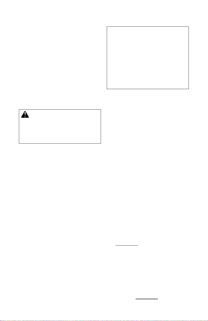
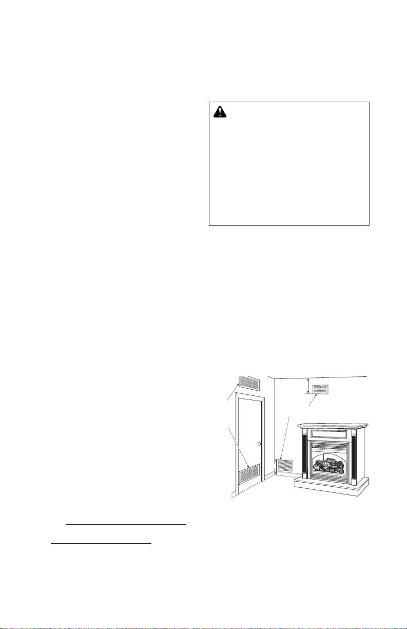
VENTILATION AIR
Ventilation Air From Inside Building
This fresh air would come from an adjoining
unconned space. When ventilating to an
adjoining unconned space, you must provide
two permanent openings: one within 12" of the
ceiling and one within 12" of the oor on the
wall connecting the two spaces (see options
1 and 2, Figure 3). You can also remove door
into adjoining room (see option 3, Figure 3).
Follow the National Fuel Gas Code, ANSI
Z223.1/NFPA 54, Air for Combustion and
Ventilation for required size of ventilation
grills or ducts.
Figure 3 - Ventilation Air from Inside
Building
Outlet
Air
Ventilated
Attic
Outlet
A
ir
Inlet
Air
Inlet Air
Ventilated
Crawl Space
To
Crawl
Space
To Attic
AIR FOR COMBUSTION AND VENTILATION
Continued
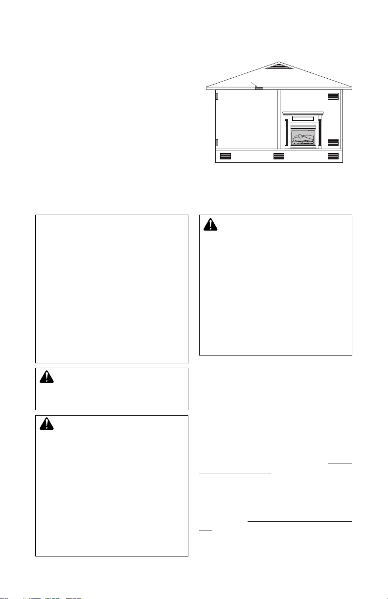
Ventilation Air From Outdoors
Provide extra fresh air by using ventilation
grills or ducts. You must provide two permanent openings: one within 12" of the ceiling
and one within 12" of the oor. Connect these
items directly to the outdoors or spaces open
to the outdoors. These spaces include attics
and crawl spaces. Follow the National Fuel
Gas Code, ANSI Z223.1/NFPA 54, Air for
Combustion and Ventilation for required size
of ventilation grills or ducts.
IMPORTANT: Do not provide openings for
inlet or outlet air into attic if attic has a thermo-
stat-controlled power vent. Heated air entering
the attic will activate the power vent.
INSTALLATION
NOTICE: This heater is intended
for use as supplemental heat.
Use this heater along with your
primary heating system. Do not
install this heater as your primary heat source. If you have a
central heating system, you may
run system’s circulating blower
while using heater. This will help
circulate the heat throughout the
house. In the event of a power
outage, you can use this heater
as your primary heat source.
WARNING: A qualied service person must install replace. Follow all local codes.
WARNING: Never install the
replace
• in a bedroom or bathroom
• in a recreational vehicle
• where curtains, furniture,
clothing, or other ammable
objects are less than 36" from
the front and 42" from the top
• in high trafc areas
• in windy or drafty areas
of replace. For side clearances see Figure 8, page 10
www.fmiproducts.com
Figure 4 - Ventilation Air from Outdoors
CAUTION: This replace cre-
ates warm air currents. These
currents move heat to wall sur-
faces next to replace. Installing
replace next to vinyl or cloth
wall coverings or operating
heater where impurities (such
as, but not limited, to tobacco
smoke, aromatic candles, clean-
ing uids, oil or kerosene lamps,
etc.) in the air exist, may discolor
walls or cause odors.
Note: Your replace is designed to be used
in zero clearance installations. Wall or framing material can be placed directly against
any exterior surface on the rear, sides, or
top of your replace, except where standoff
spacers are integrally attached. If standoff
spacers are attached to your replace, these
spacers can be placed directly against wall
or framing materials.
Use the dimensions shown for rough openings
to create the easiest installation. See Built-In
Fireplace Installation, page 11.
IMPORTANT: Vent-free heaters add moisture
to the air. Although this is benecial, installing
replace in rooms without enough ventilation
air may cause mildew to form from too much
moisture. See Air for Combustion and Ventilation, page 6.
IMPORTANT: Make sure the fireplace is
level. If replace is not level, log set will not
work properly.
119304-01H8
INSTALLATION
Continued
CHECK GAS TYPE
Use the correct gas type (natural or propane/
LP) for your replace. If your gas supply is not
correct, do not install replace. Call dealer
where you bought replace for proper type
replace.
WARNING: This appliance is
equipped for natural or propane/
LP gas but not both. Gas type is
indicated on rating plate. Field
conversion is not permitted.
ELECTRICAL HOOKUP
(Models GA3750A and GA3650TB Blower
Accessories, and GA3555 Internal
Duplex Kit)
This replace accepts a blower assembly
with an electrical cord. The electrical cord is
ve feet in length. You must locate replace
within reach of a 120 volt grounded electrical
outlet. If not, you must install an electrical
outlet within reach of replace power cord.
The GA3555 outlet accessory may be used
for built-in applications with blower accessory
installed.
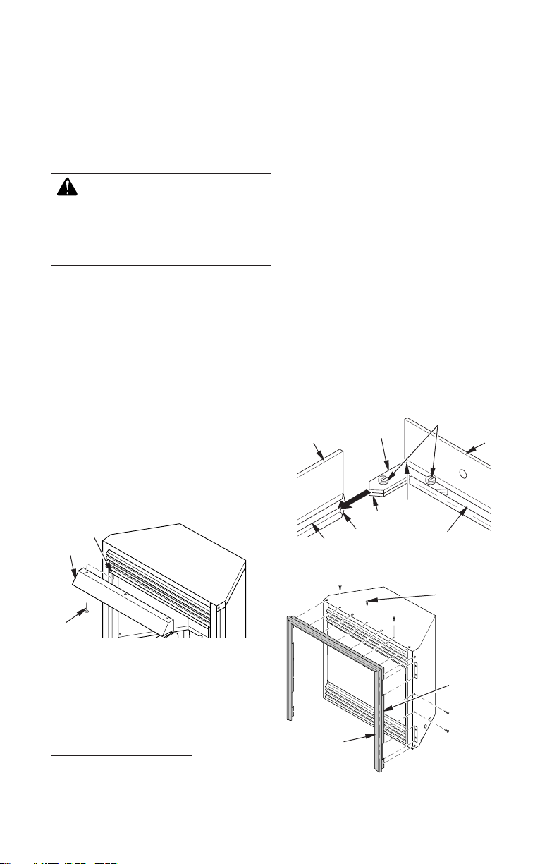
INSTALLING HOOD
Install hood to rail already installed in replace
as shown in Figure 5. Use 3 Phillips screws
provided.
Rail
Hood
1. Remove packaging from three pieces
of trim.
2. Locate four screws, two adjusting plates
with set screws, and two shims in the
hardware packet.
3. Align shim under adjusting plate as shown
in Figure 6.
4. Slide one end of adjusting plate/shim
in slot on mitered edge of top trim (see
Figure 6).
5. Slide other end of adjusting plate/shim
in slot on mitered edge of side trim (see
Figure 6).
6. While firmly holding edges of trim to-
gether, tighten both set screws on the
adjusting plate with slotted screwdriver.
7. Repeat steps 1 through 6 for other side.
8. Tighten trim hanging screws (#10 x 6.25
shoulder) into holes in cabinets. Place
the assembled trim onto replace cabinet.
Align hanging notches on trim with hanging screws on side of replace (see Figure
7). Push trim rmly into place, sliding
hanging notches over hanging screws.
Set Screws
Top
Trim
Mitered
Edge
Slot
Slot
Adjusting
Plate
Shim
Mitered
Edge
Side Trim
Figure 6 - Assembling Perimeter Trim
Trim
Hanging
Screw
Figure 5 - Installing Hood
ASSEMBLING AND ATTACHING
OPTIONAL PERIMETER TRIM
Screws
Hanging
Notches
on Trim
(Included with Mantel Accessory)
IMPORTANT: If you are recessing the rebox
in a wall, do not attach trim at this time. See
Built-In Fireplace Installation, page 11.
Note: These instructions show assembling
and attaching trim to replace.
119304-01H 9
www.fmiproducts.com
Assembled
Trim
Figure 7 - Attaching Perimeter Trim to
Fireplace
INSTALLATION
Continued
INSTALLATION CLEARANCES
WARNING: Maintain the
minimum clearances. If you can,
provide greater clearances from
oor, ceiling, and adjoining wall.
Carefully follow the instructions below. This
will ensure safe installation.
Minimum Clearances For Side Combustible
Material, Side Wall, and Ceiling
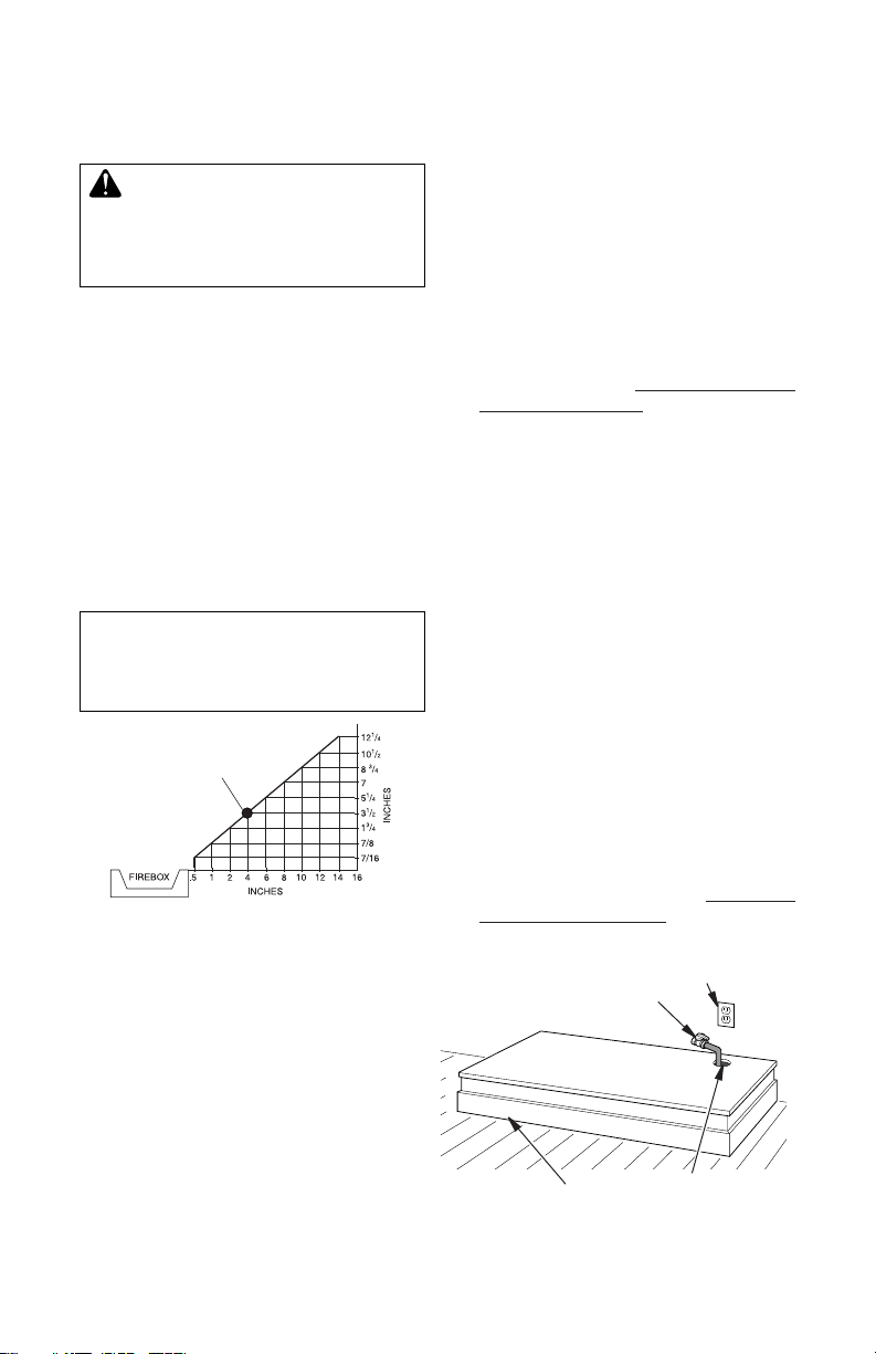
A. Clearances from the side of the replace
cabinet to any combustible material and
wall should follow diagram in Figure 8.
Example: The face of a mantel, bookshelf,
etc. is made of combustible material and
protrudes 3 1/2" from the wall. This com-
bustible material must be 4" from the side
of the replace opening (see Figure 8).
B. Clearances from top of replace opening
to ceiling should not be less than 42".
MINIMUM CLEARANCE TO
COMBUSTIBLE MATERIALS
Top 0", Left and Right Sides 16",
Bottom and Rear 0", Front 36"
Example
*
*Minimum 16" from Side Wall
Figure 8 - Minimum Clearance for
Combustible to Wall
CONVENTIONAL FIREPLACE
INSTALLATION
Conventional installation of this fireplace
involves installing replace along with the
corner, face, or cabinet mantel with hearth
base accessories against a wall in your home.
Follow the instructions in this section to install
the replace in this manner.
1. Assemble cabinet mantel, hearth base,
and trim accessories. Assembly instruc-
tions are included with each accessory.
www.fmiproducts.com
2. When installing blower, install a properly
grounded, 120 volt three-prong electrical
outlet at replace location if an outlet is not
there. If possible, locate outlet so cabinet
mantel will cover it when installed (see
Figure 9).
3. Install gas piping to replace location. This
installation includes an approved exible
gas line (if allowed by local codes) after
the equipment shutoff valve. The exible
gas line must be the last item installed on
the gas piping. See Installing Gas Piping
to Fireplace Location, page 13.
4. Place hearth base accessory against wall at
installation location. Cut an access hole in
hearth top to run exible gas line to replace
(see Figure 9). Make sure to locate access
hole so cabinet mantel will cover it when
installed.
Note: You can secure base to oor using
wood screws. Countersink screw heads
and putty over.
5. Route exible gas line through access
hole in hearth base.
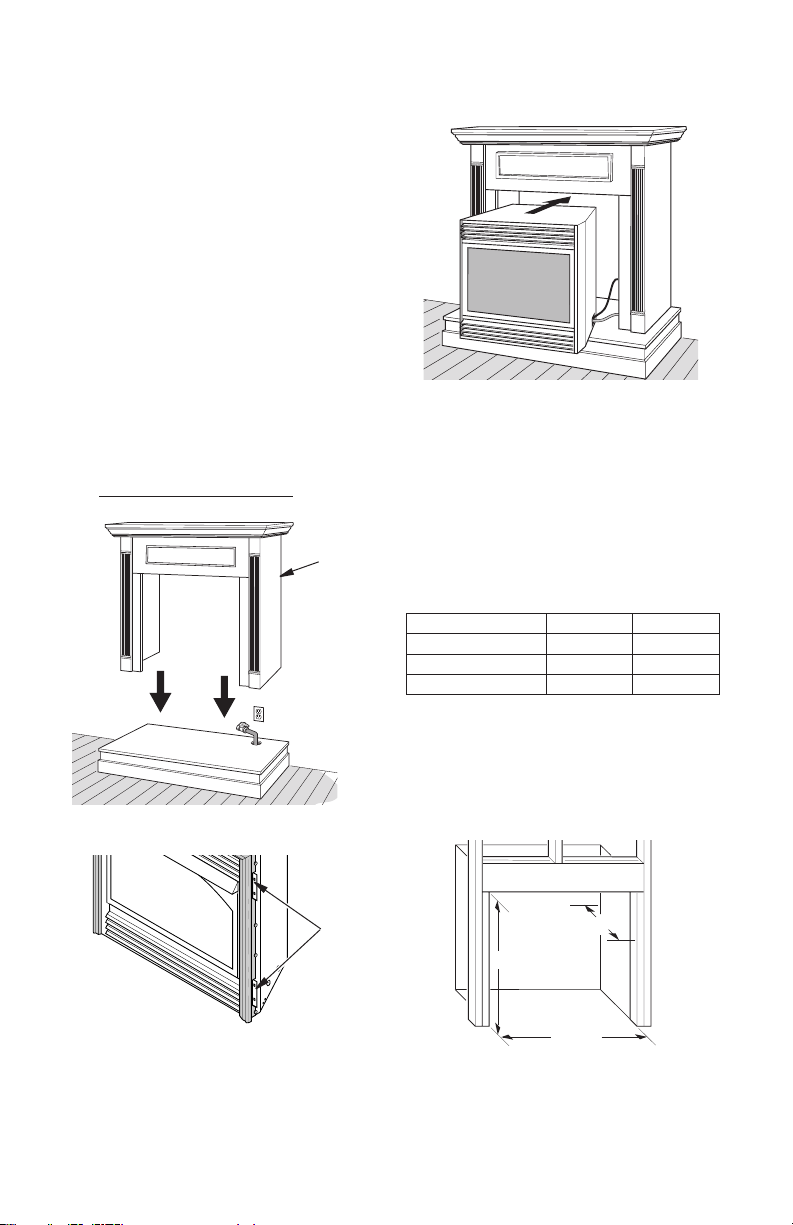
6. Center cabinet mantel on hearth base (see
Figure 10, page 11). Make sure mantel is
ush against wall.
7. Break off nailing anges (see Figure 11,
page 11) with hammer or pliers.
8. Place cardboard or other protective material on top of hearth base. Carefully set
replace on protective material, with back
of replace inside mantel opening.
9. Attach exible gas line from replace gas
regulator to gas supply. See Connecting
Fireplace to Gas Supply, page 14.
Electrical Outlet
Rigid Pipe and Gas
Shutoff Valve
Hearth Base
Figure 9 - Placing Hearth Base
Accessory Against Wall
Gas Line
Access Hole
119304-01H10
INSTALLATION
35 1/2"
17
3
/4"
33"
Continued
10. If blower is installed, route blower electri-
cal cord through access holes in either
side of replace.
Note: Bushing may be moved if neces-
sary. Plug electrical cord into electrical
outlet.
11. Carefully insert replace into cabinet mantel.
Be careful not to scratch or damage hearth
base, cabinet mantel, or any laminate trim
on hearth base. Remove protective material
from top of hearth base and from front of
replace (if any).
Note: You can secure replace to hearth
or oor. Open lower louver. Locate screw
holes in bottom of base. Tighten wood
screws through these holes and into hearth
or oor.
12. Check all gas connections for leaks. See
Checking Gas Connections, page 15.
Cabinet
Mantel
Figure 10 - Installing Cabinet Mantel
Figure 12 - Inserting Fireplace Into
Cabinet Mantel
BUILT-IN FIREPLACE
INSTALLATION
Built-in installation of this replace involves
installing replace into a framed-in enclosure.
This makes the front of replace ush with wall.
If installing a mantel above the replace, you
must follow the clearances shown in Figure
16, page 12. Follow the instructions below to
install the replace in this manner.
Actual Framing
Height 32 3/8" 33"
Front Width 34 5/16" 35 1/2"
Depth 16 11/16" 17 3/4"
1. Frame in rough opening. Use dimensions
shown in Figure 13 for the rough opening.
If installing in a corner, use dimensions
shown in Figure 14, Figure 12, for the
rough opening. The height is 33" which
is the same as the wall opening above.
Nailing
Flanges
Figure 11 - Location of Nailing Flanges
Figure 13 - Rough Opening for Installing
in Wall
119304-01H 11
www.fmiproducts.com
 Loading...