

FMI (V)CB36N(E), VCB36PE, CB36N, CB36NE, VCB36N Installation And Owner's Operation Manual
...Page 1
VENTED GAS FIREPLACE
PFS
US
INSTALLATION AND OWNER’S OPERATION MANUAL
4" B-VENT DECORATIVE GAS FIREPLACES
®
MODELS(V)CB36N(E) AND (V)CB36P(E)
WARNING: If the information in this manual is not
followed exactly, a re or explosion may result causing
property damage, personal injury or loss of life.
— Do not store or use gasoline or other ammable
vapors and liquids in the vicinity of this or any other
appliance.
— WHAT TO DO IF YOU SMELL GAS
• Do not try to light any appliance.
• Do not touch any electrical switch; do not use any
phone in your building.
• Immediately call your gas supplier from a neighbor’s
phone. Follow the gas supplier’s instructions.
• If you cannot reach your gas supplier, call the re
department.
— Installation and service must be performed by a quali-
ed installer, service agency or the gas supplier.
INSTALLER: Leave this manual with the appliance
CONSUMER: Retain this manual for future reference.
For more information, visit www.fmiproducts.com
Page 2
Safety .................................................................. 2
TABLE OF CONTENTS
Product Identication ........................................... 4
Local Codes......................................................... 4
Product Features ................................................. 5
Pre-Installation Preparation ................................. 5
Installation Precautions ....................................... 9
Venting Installation .............................................. 9
Installing Optional Controls................................ 12
Fireplace Installation.......................................... 15
Operating Fireplace ........................................... 20
SAFETY
Inspecting Burners............................................. 23
Cleaning and Maintenance ................................ 24
Specications .................................................... 25
Service Hints ..................................................... 25
Technical Services ............................................. 25
Troubleshooting ................................................. 26
Replacement Parts ............................................ 31
Accessories ....................................................... 31
Parts .................................................................. 32
Warranty ..............................................Back Cover
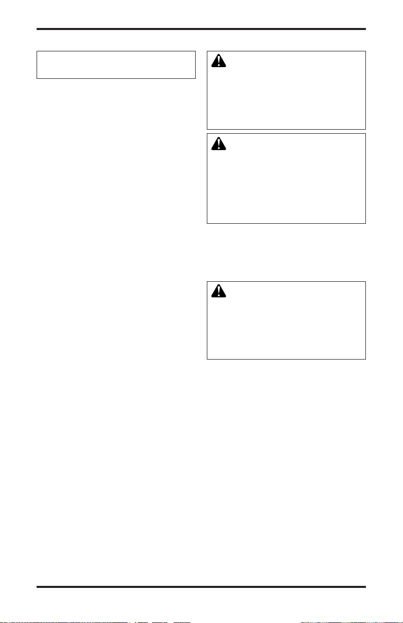
WARNING: Improper
installation, adjustment,
alteration, service or
maintenance can cause
injury or property damage. Refer to this manual
for correct installation
and operational procedures. For assistance or
additional information
consult a qualified installer, service agency or
the gas supplier.
This appliance may be in-
stalled in an aftermarket,*
permanently located,
manufactured (mobile)
home, where not prohibited by local codes.
This appliance is only for
use with the type of gas
indicated on the rating
plate. This appliance is
not convertible for use
with other gases.
* Aftermarket: Completion of sale, not for
purpose of resale, from the manufacturer
State of Massachusetts:
The installation must
be made by a licensed
plumber or gas tter in
the Commonwealth of
Massachusetts.
WARNING: This product
contains and/or generates
chemicals known to the State
of California to cause cancer or
birth defects or other reproductive harm.
IMPORTANT: Read this owner’s
manual carefully and completely
before trying to assemble, operate or service this replace.
Improper use of this replace
can cause serious injury or death
from burns, fire, explosion,
electrical shock and carbon
monoxide poisoning.
DANGER: Carbon monoxide
poisoning may lead to death!
This fireplace complies with the National
Safety Standards and is listed and tested by
PFS Corporation to ANSI Z21.50 standard as
vented gas replace.
NOTICE: Decorative product not
for use as a heating appliance.
www.fmiproducts.com
117437-01F2
Page 3
SAFETY
Continued
This replace is a vented product. This replace
will not produce any gas leakage into your
home if properly installed. This replace must
be installed by a qualied (certied or licensed)
service person. If this unit is not properly installed by a qualied service person gas and/or
carbon monoxide leakage (spillage) can occur.
Carbon Monoxide Poisoning: Early signs of
carbon monoxide poisoning resemble the u,
with headaches, dizziness or nausea. If you
have these signs, the replace may not be
working properly. Get fresh air at once! Have
replace serviced. Some people are more affected by carbon monoxide than others. These
include pregnant women, people with heart or
lung disease or anemia, those under the inuence of alcohol and those at high altitudes.
Natural and Propane/LP Gas: Natural and
propane/LP gases are odorless. An odor-making agent is added to these gases. The odor
helps you detect a gas leak. However, the
odor added to the gas can fade. Gas may be
present even though no odor exists.
Make certain you read and understand all
warnings. Keep this manual for reference. It
is your guide to safe and proper operation of
this replace.
WARNING: Any change to
this replace or its controls can
be dangerous.
WARNING: Do not use a blower insert, heat exchanger insert
or other accessory not approved
for use with this replace.
WARNING: Do not allow fans
to blow directly into the replace.
Avoid any drafts that alter burner
ame patterns. Ceiling fans can
create drafts that alter burner
ame patterns. Altered burner
patterns can cause sooting.
117437-01F 3
www.fmiproducts.com
Due to high temperatures, the
appliance should be located out
of trafc and away from furniture
and draperies.
Do not place clothing or other
ammable material on or near
the appliance. Never place any
objects on or around replace.
Fireplace reaches high temperatures. Keep children and adults
away from hot surface to avoid
burns or clothing ignition. Fireplace will remain hot for a time
after shutdown. Allow surfaces
to cool before touching.
Do not operate replace with
glass door removed, cracked
or broken.
Carefully supervise young chil-
dren when they are in the room
with the replace.
Keep the appliance area clear
and free from combustible materials, gasoline and other ammable vapors and liquids.
This product is intended only
as a supplement to your central
heating system and is not to be
installed as a primary source of
heat. You may use this product
for emergency heating during a
power outage.
1. This appliance is only for use with the type
of gas indicated on the rating plate. This
appliance is not convertible for use with
other gases unless a certied kit is used.
2. Do not place propane/LP supply tank(s)
inside any structure. Locate propane/
LP supply tank(s) outdoors (propane/LP
units only).
Page 4
3. If you smell gas
• shut off gas supply
• do not try to light any appliance
• do not touch any electrical switch; do not
use any phone in your building
• immediately call your gas supplier from
a neighbor’s phone. Follow the gas sup-
plier’s instructions
• if you cannot reach your gas supplier,
call the re department
4. Never install the replace
• in a recreational vehicle
• in windy or drafty areas where curtains
or other combustible (ammable) objects
can make contact with the replace front
• in high trafc areas
5. Do not modify this replace under any
circumstances. Any parts removed for
servicing must be replaced prior to operat-
ing replace.
6. Turn fireplace off and let cool before
servicing, installing or repairing. Only a
qualied service person should install,
service or repair this replace.
7. You must keep control compartments,
burners and circulating air passages
clean. More frequent cleaning may be
needed due to excessive lint and dust
from carpeting, bedding material, etc.
Turn off the gas valve and pilot light before
cleaning replace.
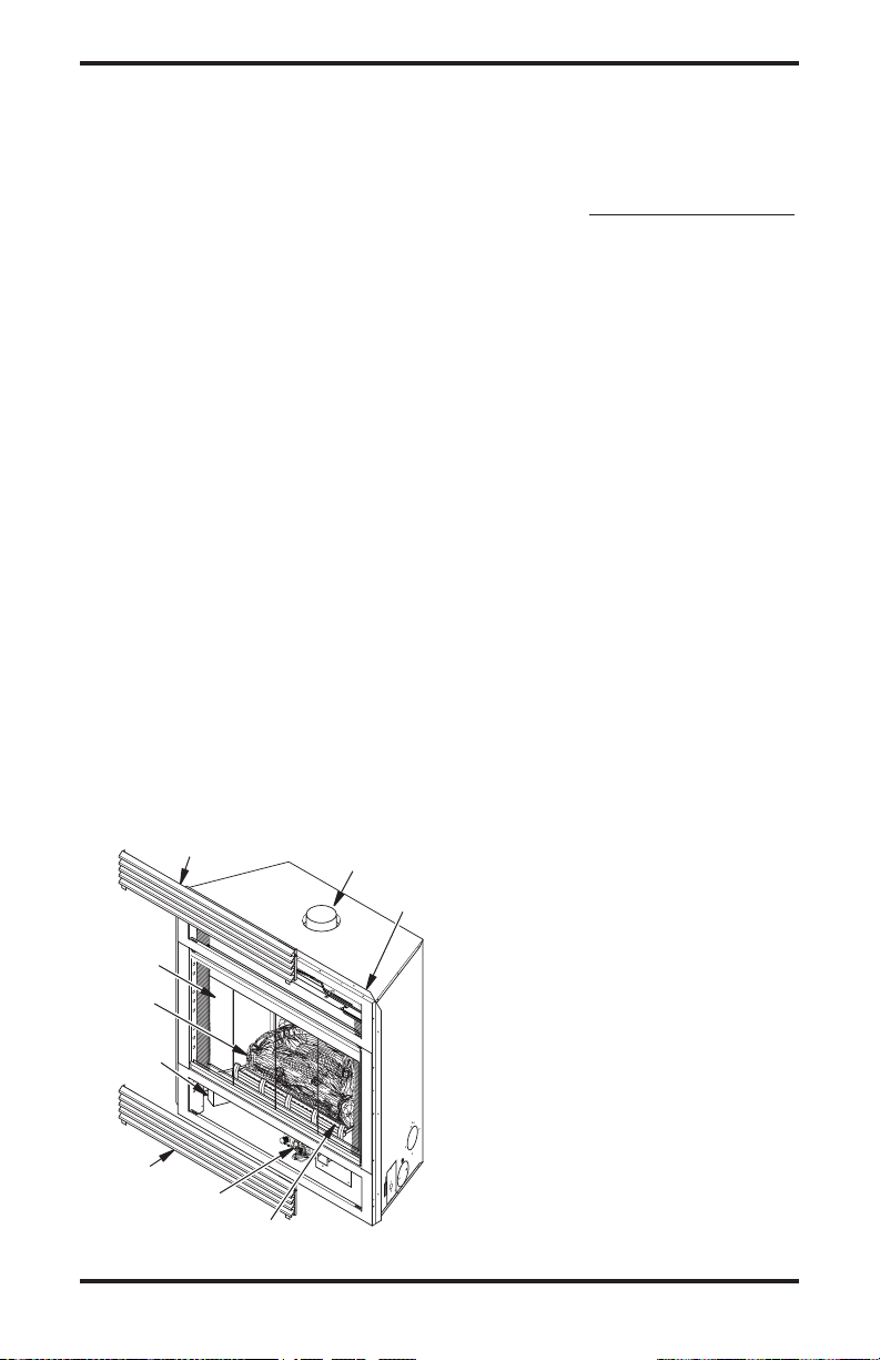
PRODUCT
IDENTIFICATION
Top Louver Panel
Glass
Door
Assembly
Log Set
Junction Box
(Electronic
Ignition Only)
4" B-Vent
Flue Collar
Nailing
Flange
SAFETY
Continued
8. Have replace and venting system inspected annually by a qualied service person.
If needed, have venting system cleaned or
repaired. See Cleaning and Maintenance,
page 24.
9. Do not use this replace to cook food or
burn paper or other objects.
10. Do not use any solid fuels (wood, coal, paper, cardboard, etc.) in this replace. Use
only gas type indicated on nameplate.
11. This appliance, when installed, must be
electrically grounded in accordance with
local codes or, in the absence of local
codes, with the National Electric Code,
ANSI/NFPA 70.
12. Do not use replace if any part has been
exposed to or under water. Immediately
call a qualied service technician to arrange for replacement of the unit.
13. Do not operate replace if any log is broken or missing.
14. To prevent performance problems, do
not use propane/LP fuel tank of less than
100 lb. (45 kg) capacity (propane/LP
units only).
15. Provide adequate clearances around air
openings.
LOCAL CODES
Install and use replace with care. Follow all
local codes. In the absence of local codes,
use the latest edition of The National Fuel
Gas Code ANSI Z223.1/NFPA 54*.
*Available from:
American National Standards Institute, Inc.
1430 Broadway
New York, NY 10018
National Fire Protection Association, Inc.
Batterymarch Park
Quincy, MA 02269
Bottom
Louver
Panel
Control
Valve
Figure 1 - B-Vent Fireplace
Ember Tray
www.fmiproducts.com
117437-01F4
Page 5
PRODUCT FEATURES
These are a few facts that can help you un-
derstand and enjoy your vented decorative
replace:
• The (V)CB36N(E) and (V)CB36P(E) series
of vented decorative replaces may be
recessed into an exterior chase, an interior
ush wall enclosure or a framed-in corner
installation.
• Models (V)CB36N and (V)CB36P are
equipped with a millivolt gas control system
that does not require electricity to operate.
A piezo ignitor is provided to light the pilot
without using matches or lighters.
• Models (V)CB36N(E) and (V)CB36P(E)
are equipped with an electronic ignition
system that requires 120 VAC to operate.
An electrode ignitor automatically lights the
pilot ame when the replace is turned on.
• These replaces can accept any approved
4" B-Type venting system and must be
terminated vertically through the roof using
PRE-INSTALLATION PREPARATION
LOCATION AND SPACE
REQUIREMENTS
Determine the safest and most efcient location for your FMI PRODUCTS, LLC B-vent
replace. Make sure that rafters and wall
studs are not in the way of the venting system.
Choose a location where the heat output is
not affected by drafts, air conditioning ducts,
windows or doors. Figure 2 shows some common locations. Be aware of all restrictions and
precautions before deciding the exact location
for your replace and termination cap.
When deciding the location of your replace,
follow these rules:
• Do not connect this replace to a chimney
ue servicing a separate solid fuel burning
replace or appliance.
• Do to high temperatures, do not locate this
replace in high trafc areas, windy or drafty
areas, or near furniture or draperies.
• Proper clearances must be maintained.
• If your replace is to be installed directly on
carpeting, vinyl, tile or any combustible material other than wood, it must be installed on a
metal or wood panel extending the full width
and depth of the replace (see Figure 3).
a listed type vent cap only. See venting
instructions starting on page 8 for proper
venting requirements.
• These vented replaces require indoor air
for combustion and must be installed in a
room of sufcient size to provide adequate
fresh air for safe and proper operation. The
room intended for installation must be of
sufcient size to meet the requirements
for an unconned space as dened in the
National Fuel Gas Code, ANSI Z223.1/
NFPA 54. Air for Combustion and Ventilation. If sufcient air for combustion is not
available a makeup air kit model AK4 may
be required to provide outside air to this
appliance. Check your local codes as to
specic requirements for make up air.
• This replace may be installed in any room
of the house provided all local codes and
these installation instructions are followed.
• Only trim kits supplied by FMI PRODUCTS,
LLC shall be used in the installation of this
replace, see Accessories, page 31.
• Do not install aftermarket vent dampers.
Manual or automatic vent dampers are not
approved for use with this appliance.
Flush with a wall
Through exterior wall
Corner
Installation
enclosed in a chase
Figure 2 - Common Fireplace Locations
25"
(63.5 cm)
36"
(91.4 cm)
36"
(91.4 cm)
Figure 3 - Fireplace Bottom Dimensions
117437-01F 5
www.fmiproducts.com
Page 6
PRE-INSTALLATION PREPARATION
Continued
• Your replace is designed to be used in
zero clearance installations. Wall or framing
material can be placed directly against any
exterior surface on the back, sides or top
of your replace, except when clearances
are required from ue vent pipe, see Clear-
ances.
• If recessed into a wall, you can avoid extra
framing by positioning your replace against
an already existing framing member.
• A hearth extension is not required with
this appliance. If one is installed, it is for
aesthetic purposes only and does not have
to meet standard requirements for hearth
extensions.
• If you plan on installing a television or
entertainment center recessed above your
replace, it is recommended that you maintain a minimum 18" (45.7 cm) above the top
of louver opening.
• When locating the termination cap, it is im-
portant to observe the minimum vent height
and clearances required under code, see
Venting Installation Instructions, page 9.
• Do not recess termination cap into a wall
or siding.
• You may paint the termination cap with 450°
F (232° C) heat resistant paint to coordinate
with the exterior nish.
PACKAGING AND REMOVAL
The (V)CB36 vented decorative gas replaces
are packaged with the following items:
• one box containing a 4 piece log set located
on the burner in the rebox.
• one bag containing the owner’s manual
with installation instructions, operator’s
guide, and warranty information.
• one bag of glowing ember material.
• one bag of vermiculite hearth treatments.
1. Remove shrink wrap securing 2 carton
trays to unit.
2. Lift top carton tray off and remove four
corner posts.
3. Discard bottom tray once unit is moved
into position.
Note: To prevent damage to ceramic logs and
glass panels you may want to remove them
before positioning and framing the unit. To
access rebox, see Louver Panels and Glass
Door, page 17.
Carton
Tray
Corner
Post
Glass
Panel
Log
Carton
Figure 4 - Unpacking Fireplace
CLEARANCES
Minimum clearances to combustibles for
replace:
Back, Sides, Floor and Top
Perpendicular walls 10" (25.4 cm)
Ceiling to Louver & Front 36" (91.4 cm)
B-Vent Surfaces 1" (26 mm) (See venting
Mantel Clearances (See Mantel Clearances,
Combustible material with a maximum thick-
ness of 5/8" (16 mm) may be ush with top
and sides of front face of replace.
0" (0 mm)
instructions for specics
on vent clearances.)
page 8, for specic clear-
ances to combustible
mantels.)
FRAMING AND FINISHING
Figure 5, page 7, shows typical framing of this
replace. Figure 6, page 7, shows framing for
corner installation. All minimum clearances
must be met.
For overall unit dimensions, framing allowances and vent collar locations, see Figure
7 on page 7.
For available accessories for this replace,
see Accessories, page 31. If you are using a
separate combustible mantel piece, refer to
Figures 8 and 9, page 8, for proper height and
clearances. You can install a noncombustible
mantel at any height above the fireplace
opening.
Note: Noncombustible mantels may discolor!
www.fmiproducts.com
117437-01F6
Page 7
36 1/4"
(39 cm)
(92.1 cm)
PRE-INSTALLATION PREPARATION
Continued
21" (53.3 cm)
To Center of
Top Vent
28 5/8"
(72.7 cm)
36"
(91.4 cm)
**These dimensions allow for 1" clearance at
sides and back of replace. However, 0" clearance
is also permitted at all sides when framed.
Figure 6 - Framing Clearances for Corner
14 3/4"
(37.5 cm)
(144 cm)
Installation
14 3/4"
(37.5 cm)
**
3
14
/4" (37.5 cm)
to Nailing
Flanges
1
12
/4"
(31 cm)
to Opening
3
56
/4"
Figure 5 - Framing Clearances for Flush
Wall Installation
7 7/8" (20 cm) to
Center of 4" B-Vent
7
/8"
5
(15 cm) to
Nailing
Flange
" (92.1 cm)
4
/
1
36
3
35
/4"
(90.8 cm)
8" (20.3 cm)
Gas Supply
Inlet
Wall Switch
Wireway
to Nailing Flange
" (93.4 cm)
4
/
3
36
" (11.4 cm) Electrical Inlet
2
/
1
4
Figure 7 - Unit Dimensions
38"
(96.5 cm)
36 1/4" (92.1 cm)
Face Dimensions
37" (94 cm)
to Nailing Flange
2"
(5.1 cm)
14 3/4" (37.5 cm)
to Nailing Flanges
1
/4"
1
(3.2 cm)
36" (91.4 cm)
Face Dimensions
" (6.4 cm)
" (3.8 cm)
2
/
2
/
1
1
2
1
5/8"
(16 mm)
Wall Switch
Wireway
1
/8"
11
(28.3 cm)
Air Kit Location
3
/8"
15
6" (15.2 cm)
117437-01F 7
www.fmiproducts.com
Page 8
PRE-INSTALLATION PREPARATION
Side Wall
Continued
MANTEL CLEARANCES
Figure 8 shows projected mantel depths at
various heights above top of louver opening.
Figure 7, page 7, shows minimum allowable
distances from various mantel components in
relation to both sides of replace opening.
WARNING: When nishing
appliance do not overlap combustible materials onto the black
front face. Brick, tile or other
noncombustible materials may be
applied to the face provided that
any replace openings are not
blocked and gaps in the material
used and the face are sealed with
a noncombustible caulking.
Outer
Surround
Combustible
Material May
Be Used
1 1/2"
(3.8 cm)
5 1/4"
(13.3 cm)
1
(4.4 cm)
To Fireplace
Opening
1
3
/2"
(8.9
cm)
3
/4"
10" (25.4 cm)
Figure 8 - Side Clearances for
Combustible Mantels
Safe
Zone
Perpendicular
33°
1
A
B
C
Top of Louver
D
E
Opening
2
3
4
5
6
7
F
G
Stud Wall
2 x 4 Header
at 1" Min.
Clearance
4" B-Vent
Flue Pipe
Mantel from
Top of Louver
Ref. Mantel Depth Ref.
Opening
1 16" (40.6 cm) A 18" (45.7 cm)
2 14" (35.6 cm) B 16" (40.6 cm)
3 12" (30.5 cm) C 14" (35.6 cm)
4 10" (25.4 cm) D 12" (30.5 cm)
5 8" (20.3 cm) E 10" (25.4 cm)
6 4" (10.2 cm) F 8" (20.3 cm)
7 2" (5.1 cm) G 6" (15.2 cm)
Figure 9 - Clearances for Combustible
Mantels
www.fmiproducts.com
117437-01F8
Page 9
INSTALLATION PRECAUTIONS
NOTICE: Failure to follow these
instructions will void the warranty.
• Wear gloves and safety glasses for
protection
• Use extreme caution when using ladders
or when on roof tops
• Be aware of electrical wiring locations in
walls and ceilings
The following actions will void the warranty
on this product:
• Installation of any damaged venting
component
• Unauthorized modication of the venting
system (Do not cut or alter vent components)
• Installation of any component part not
manufactured or approved by FMI PRODUCTS, LLC
• Installation other than as instructed by
these instructions
VENTING INSTALLATION
A 4" B-type venting system must be connected
to the appliance for venting to the outside of
the building.
The following section is provided as a guide to
install a standard B-type vent installation.
Standing code requirements concerning
B-type vent installations may vary within
your state, province or local codes jurisdiction. Therefore, it is recommended that you
check with your local building code authority
for specic requirements or in absence of
local codes, follow Section 7.0 of the cur-
rent National Fuel Gas Code NFPA 54/ANSI
Z223.1 for Category I systems using double
wall B-1 vent pipe.
This gas appliance must be vented to the
outdoors only and may not be terminated into
an attic space or into a chimney ue servicing
a solid fuel burning appliance.
This appliance may be vented through a
manufactured chimney liner system if all are
listed, inspected and approved by local codes
and/or building authorities.
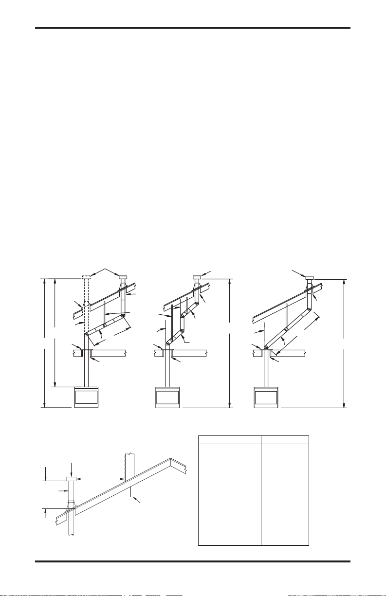
The examples shown in Figure 10, page 10,
are typical of most B-vent installations and
code practices.
WARNING: Read all instruc-
tions completely and thoroughly
before attempting installation.
Failure to do so could result in
serious injury, property damage
or loss of life.
WARNING: B-type vent pipe
airspace clearance to combustibles is 1" on all sides. Where
the vent pipe passes through a
vertical wall a listed thimble approved for use with B-type vent
must be used.
WARNING: This gas replace
and vent assembly must be vented
directly to the outside. The venting
system must NEVER be attached
to a chimney serving a separate
solid fuel burning appliance.
Example 1: Shows the minimum allowable sys-
tem height and lateral offset for a 60° or greater
inclination. Code species that offsets at 60° or
greater are considered horizontal and must fol-
low the 75% rule for lateral to total vertical sys-
tem height. Codes also allows only one offset
in the total system when at 60° or greater. The
total vertical height in this example represents
the minimum height of 8 feet and therefore the
allowable lateral is 6 feet when the 75% rule
applies. If the lateral length must exceed 75%
then the system must be sized in accordance
with the Category I venting tables.
Example 2: Shows multiple offsets each at
45° of inclination. Multiple offsets are permitted if they do not exceed 45° of inclination.
The total lengths of the two offsets are not
required to meet the 75% rule.
Example 3: Shows a single offset at 45° of
inclination and therefore the lateral length at 10
feet of offset does not have to meet the 75%
allowable rule.
117437-01F 9
www.fmiproducts.com
Page 10
VENTING INSTALLATION
Continued
In each case the offsets must be supported
and restops must be positioned wherever
the vent must pass through a sub-oor, ceiling joist or an attic overhang. The vent pipe
must terminate vertically into a listed type vent
cap and extend a sufcient height through
an approved roof ashing, roof jack or a roof
thimble. At all points the listed clearances
must be maintained.
Vent terminations must be located in accordance with height and proximity rules of
NFPA No. 54. These rules apply to vents at
12" diameter or less and require a minimum
height in accordance with the roof pitch and
a minimum of 8 foot distance from a vertical
wall or obstruction (see Figure 11).
If venting horizontally through a side wall be-
comes necessary, a listed thimble approved
for use with B-type vent must be used. Check
with your local codes before venting through
a side wall.
Maintain
Listed
Clearance
8'
Position
Firestop
12' Min.
Listed
Vent Cap
60
6'
Maintain
Listed
Clearance
Maintain
Listed
Clearance
Support Each
Lateral At
Least Every
6 Feet
Position
Firestop
Maintain
Listed
Clearance
Some codes areas allow the use of existing Btype vent systems if the system is at or above
the recommended diameter of the ue.
The ue connection must be made using listed
B-type connectors and the existing system
must be code inspected for damage and proper
installation.
It is not recommended that this appliance be
common vented with and existing gas burning
appliance. However, if it becomes necessary
to common vent the appliance. The venting
system must be sized and congured in ac-
cordance with the common venting guides
Appendix G of the current National Fuel Gas
Code NFPA No. 54/ANSI Z223.1.
Note: Before connecting this appliance to an
existing vent system or a common venting
system consult with your local architect plan-
ner, or building ofcial.
CHECKING FOR PROPER VENTING
45
45
Listed
Vent Cap
Maintain
Listed
Clearance
12' Min.
Position
Firestop
45°
Listed
Vent Cap
Maintain
Listed
Clearance
Maintain
Listed
Clearance
10'
12' Min.
EXAMPLE 1
Lowest
Discharge
Opening
Listed
Gas
Vent
H (Min)
Height
From Roof
Listed
Vent Cap
8 Ft. Min.
Figure 10 - Typical B-Vent Conguration
Roof Pitch H (Min.)
Flat to 6/12 1.0 ft (0.3 m)
6/12 to 7/12 1.25 ft (0.38 m)
Over 7/12 to 8/12 1.5 ft (0.46 m)
Over 8/12 to 9/12 2.0 ft (0.61 m)
Over 9/12 to 10/12 2.5 ft (0.76 m)
x
12
Roof Pitch x/12
Listed Clearance
Over 10/12 to 11/12 3.25 ft (0.99 m)
Over 11/12 to 12/12 4.0 ft (1.22 m)
Over 12/12 to 14/12 5.0 ft (1.52 m)
Over 14/12 to 16/12 6.0 ft (1.83 m)
Over 16/12 to 18/12 7.0 ft (2.13 m)
Over 18/12 to 20/12 7.5 ft (2.27 m)
Over 20/12 to 21/12 8.0 ft (2.44 m)
Figure 11 - B-Vent Termination
www.fmiproducts.com
EXAMPLE 3EXAMPLE 2
117437-01F10
Page 11
VENTING INSTALLATION
Continued
After completing and checking electrical,
gas and vent connections, follow lighting
instructions and allow main burner to run for
approximately 5 minutes. Hold a match or
butane lighter ame, near opening between
glass and replace face and play it along
entire length of opening (Smoke may also be
used). Proper venting will tend to draw ame
or smoke into appliance. Improper venting,
escaping or spillage of burned gas, is indicated when match ickers or goes out (see
Figure 12). Smoke will also tend to disperse
away from appliance.
If appliance is not venting properly, shut it off
and notify your installer or a qualied service
agency to inspect venting system.
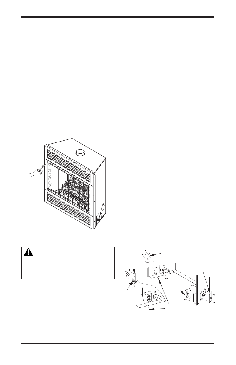
ELECTRICAL SUPPLY CONNECTION
Figure 12 - Checking for Spillage
Note: If you do not need to relocate the junc-
tion box, to connect the electric supply follow
steps 8 through 11 only:
1. Remove 2 screws and outer cover with
strain relief bushing on right side of cabi-
net (see Figure 13).
2. Remove inner retaining screw on junction
box mounting tab.
3. Slide junction box up until screw mounting
tab is lined up to notch in outer cabinet.
4. Swing junction box out and slip retaining
ange out through slot in outer cabinet.
5. Remove 2 screws and outer cover on left
side of outer cabinet.
6. Reinsert junction box retaining flange
through slot now on left side and swing
screw mounting tab back through notch
as before.
7. Slide junction box down till mounting tab
holes line up and replace inner retaining
screw.
8. With junction box cover removed, pull
end of 3-wire Romex supply line through
universal strain relief bushing on cover.
(see Figure 13).
9. Strip back outer Romex to about 4" and
connect black, white and green wires accordingly using 3 wire nut connectors.
10. Tuck tailing wires into junction box and
replace junction box cover using 2 remaining screws.
11. Tighten adjustment on universal strain
bushing to secure Romex sheathing and
complete supply connection.
J-Box
CAUTION: Disconnect the
electrical power to the supply
circuit before attempting to con-
Cover
with Strain
Relilef
nect or service this appliance.
A prewired junction box receptacle with strain
relief is provided on right side of cabinet for
hard wiring unit to a 15 Amp, 120 VAC, 60 Hz
grounded branch circuit. If installation demands
electrical supply be connected from the left, the
entire receptacle box can be relocated to the
left side by following these instructions:
117437-01F 11
www.fmiproducts.com
Romex
Cable
Figure 13 - Relocating Junction Box Recep-
tacle and Electrical Supply Connection
J-Box
Cover
J-Box with
Receptacle
Screw/Tab
Retainer
J-Box Cover
with Strain
Relief
Page 12

VENTING INSTALLATION
or Wall Switch
Continued
WARNING: This appliance,
when installed must be electrically grounded in accordance
with local code or in the absence
of local code, with the current
National Electric Code, ANSI/
NFPA 70.
HIGH ALTITUDE INSTALLATION
Your FMI PRODUCTS, LLC B-vent replace
has been tested and approved in the USA for
elevations from 0-2,000 feet.
INSTALLING OPTIONAL CONTROLS
INSTALLING OPTIONAL WALL
MOUNT SWITCH - GWMS2
1. Connect one terminal of 15 foot wire from
wall switch to male connector on high limit
harness. Connect remaining wire terminal
to TH terminal on valve. Make sure that
wire terminals are in positions on unit as
pictured in Figure 14. If wires are not connected as shown switch will not work.
2. Route 15 foot wire through hole openings
with bushings provided on either side of
replace cabinet.
3. Connect one bare wire end to each of
terminals of GWMS2 wall switch.
4. Install wall switch and cover in wall.
When installing a non-high altitude replace
at an elevation above 2,000 feet, you may
need to decrease the input rating by changing
the existing burner orice to a smaller size.
Reduce input 4% for each 1,000 feet above
sea level. Check with your local gas company
for proper orice size identication.
Consult your local gas company to help deter-
mine the proper orice for your location.
For assistance with any high altitude installa-
tion contact FMI PRODUCTS, LLC’s Customer Service Department at 1-866-328-4537.
IMPORTANT: Do not use any other wire than
that provided with GWMS2 wall switch kit. Do
not exceed 15 feet of distance from valve con-
nection. Using wire of higher gauge or turns
or exceeding minimum distance will increase
resistance at control valve causing unreliable
performance of replace controls.
Remote Receiver
or Wall Switch to
Terminal Marked “TH”
Figure 14 - Connecting Remote Receiver
or Wall Switch to the Gas Control Valve
Wire Harness From
High Limit Switch
Male Connector to
Remote Receiver
www.fmiproducts.com
117437-01F12
Page 13

INSTALLING OPTIONAL CONTROLS
Continued
INSTALLING OPTIONAL WIRELESS
REMOTE CONTROL - MODEL WRC
(Electronic Ignition)
Installing and Activating the Remote
Receiver
1. Open bottom louver and locate plug receptacle. Plug receptacle is located either
on right or left side of cabinet.
2. The WRC model receiver does not require
a battery. Receiver can be installed by
rst plugging short extension cord into
replace receptacle. Then plug receiver
unit into extension cord. Finally plug ignition module plug into receiver unit (see
Figure 15).
3. Activate remote handset battery by re-
moving insulating tab on back of handset
(see Figure 16). Battery is included pre
installed
4. Once battery is activated unit is ready to
use.
5. Replace bottom louver panel.
Fireplace
Receptacle
Extension Cord
Figure 15 - Installing WRC Remote Receiver
Battery Cover
12 Volt Battery
Figure 16 - Installing Battery into Back of
Back of Handset
Handset
Remote
Control
Receiver
Ignition
Module
Plug
Pull to
Remove
Insulation
Tab
117437-01F 13
www.fmiproducts.com
Page 14

Millivolt Wiring Diagram
Pilot Burner
INSTALLING OPTIONAL CONTROLS
Continued
WIRING DIAGRAMS
NOTICE: This appliance is equipped with a vent safety shutoff switch
which will shut down the appliance in case of a venting problem. Do
not bypass the vent safety shutoff switch. If the appliance should
shut down, have a qualied installer, service agency, or your gas
supplier inspect the vent before operating.
CAUTION: label all wires prior to disconnection when servicing
controls. Wiring errors can cause improper and dangerous operation. Verify proper operation after servicing.
Incoming
Main Gas
Supply
Gas Valve
EV1
Pilot
Burner
N
O
T
O
L
I
P
F
F
O
Figure 17 - Millivolt Ignition Wiring Diagram
ELECTRONIC IGNITION
High Limit
Switch
WIRING DIAGRAM
NC
Black
Black
Black
Thermocouple
Replace factory wiring with
105° C equivalent or higher rating
External wiring use only Class 2
thermostat wire 18 Ga. Red/White
Red
MV PV TH P/MV GND TR
RED
WHITE
TH
TP
TH/TP
HIGH LIMIT
SWITCH
NC
Wall Switch/Remote Receiver
Ignitor
Orange
Ignition Control
Module
Red
Transformer
24 VAC
DO NOT
CONNECT
TO 120V
White
EV2
High Voltage
Blue
Green
Blue
Ignition Module
Figure 18 - Electronic Ignition Wiring Diagram
www.fmiproducts.com
Ground
120 VAC
117437-01F14
Page 15

FIREPLACE INSTALLATION
CHECK GAS TYPE
Use only the correct type of gas (natural or
propane/LP). If your gas supply is not the
correct gas type, do not install replace. See
dealer where you purchased your replace for
proper gas type replace or to purchase gas
conversion kit (see Accessories, page 31).
INSTALLING GAS PIPING TO
FIREPLACE LOCATION
WARNING: A qualified
service person must connect
replace to gas supply. Follow
all local codes.
CAUTION: For propane/LP
units, never connect fireplace
directly to the propane/LP supply.
This replace requires an external
regulator (not supplied). Install the
external regulator between the
replace and propane/LP supply.
Installation Items Needed
Before installing replace, make sure you
have the items listed below.
• external regulator (supplied by installer)
• piping (check local codes)
• sealant (resistant to propane/LP gas)
• equipment shutoff valve *
• test gauge connection *
• sediment trap
• tee joint
• pipe wrench
• approved exible gas line with gas connector (if allowed by local codes)
* An equipment shutoff valve with 1/8" NPT
tap is an acceptable alternative to test gauge
connection. Purchase the equipment shutoff
valve from your retailer.
For propane/LP connection only, installer
must supply an external regulator. External
regulator will reduce incoming gas pressure.
You must reduce incoming gas pressure to
between 11" and 14" of water. If you do not
reduce incoming gas pressure, fireplace
regulator damage could occur. Install external
regulator with vent pointing down as shown in
Figure 19. Pointing vent down protects it from
freezing rain or sleet.
117437-01F 15
www.fmiproducts.com
CAUTION: Use only new,
black iron or steel pipe. Internally-tinned copper tubing may
be used in certain areas. Check
your local codes. Use pipe of
1/2" diameter or greater to allow
proper gas volume to replace.
If pipe is too small, undue loss
of volume will occur.
Installation must include an equipment shutoff
valve, union and plugged 1/8" NPT tap. Locate
NPT tap within reach for test gauge hook up.
NPT tap must be upstream from replace
(see Figure 20).
Propane/LP Supply Tank
External
Regulator
with Vent
Pointing
Down
Figure 19 - External Regulator with Vent
Pointing Down (Propane/LP Only)
Equipment Shutoff Valve
with 1/8" NPT Tap*
Approved
Flexible
Gas Line
3" Minimum
Cap Pipe Tee Joint
Nipple
Sediment Trap/Drip Leg
Figure 20 - Gas Connection
* The equipment shutoff valve may be supplied with the appliance or you can purchase
it from your retailer.
Natural - From
Gas Meter (5.5"
W.C. to 10.5" W.C.
Pressure)
Propane/LP From
External Regulator
(11" W.C. to 14"
W.C. Pressure)
Page 16

FIREPLACE INSTALLATION
Continued
IMPORTANT: Install main gas valve (equipment shutoff valve) in an accessible location.
The main gas valve is for turning on or shutting
off gas to appliance.
Check your building codes for any special
requirements for locating equipment shutoff
valve to replaces.
Apply pipe joint sealant lightly to male NPT
threads. This will prevent excess sealant from
going into pipe. Excess sealant in pipe could
result in clogged replace valves.
WARNING: Use pipe joint
sealant that is resistant to liquid
petroleum (LP) gas.
We recommend that you install a sediment
trap/drip leg in supply line as shown in Figure
20, page 15. Locate sediment trap/drip leg
where it is within reach for cleaning. Install
in piping system between fuel supply and
replace. Locate sediment trap/drip leg where
trapped matter is not likely to freeze. A sediment trap traps moisture and contaminants.
This keeps them from going into replace
gas controls. If sediment trap/drip leg is not
installed or is installed wrong, replace may
not run properly.
CONNECTING FIREPLACE TO GAS
SUPPLY
Installation Items Needed
• 3/4" and a 7/8" open end wrench or adjustable wrench
• sealant (resistant to propane/LP gas, not
provided)
1. Remove lower louver door panel by lifting
up until disengaged. Swing forward and
out of locating slots at bottom.
2. Route exible gas line (provided by in-
staller) from equipment shutoff valve to
replace. Route exible gas supply line
through one access hole on each side of
replace cabinet.
3. Attach exible gas line from gas supply
to the 1/2" are tting provided on control
valve (see Figure 21).
4. Check all gas connections for leaks (see
Checking Gas Connections).
www.fmiproducts.com
To Gas Supply
(Natural)
To External
Regulator
(Propane/LP)
Flexible Gas Line
Do NOT Kink
Control Valve
Figure 21 - Connecting Flexible Gas Line
to Millivolt Valve
Equipment
Shutoff Valve
CHECKING GAS CONNECTIONS
WARNING: Test all gas piping
and connections, internal and
external to unit, for leaks after
installing or servicing. Correct
all leaks at once.
WARNING: Never use an open
ame to check for a leak. Apply
noncorrosive leak detection uid
to all joints. Bubbles forming show
a leak. Correct all leaks at once.
PRESSURE TESTING GAS SUPPLY
PIPING SYSTEM
Test Pressures In Excess Of 1/2 PSIG
(3.5 kPa)
1. Disconnect replace and its individual
equipment shutoff valve from gas supply
piping system. Pressures in excess of 1/2
psig (3.5 kPa) will damage replace gas
regulator.
2. Cap off open end of gas pipe where equipment shutoff valve was connected.
3. Pressurize supply piping system by either
opening propane/LP supply tank valve
for propane/LP gas replace or opening
main gas valve located on or near gas
meter for natural gas replace or using
compressed air.
4. Check all joints of gas supply piping system. Apply noncorrosive leak detection
uid to all joints. Bubbles forming show a
leak. Correct all leaks at once.
5. Reconnect fireplace and equipment
shutoff valve to gas supply. Check reconnected ttings for leaks.
117437-01F16
Page 17

FIREPLACE INSTALLATION
Continued
Test Pressures Equal To or Less Than
1/2 PSIG (3.5 kPa)
1. Close equipment shutoff valve (see Figure 22).
2. Pressurize supply piping system by either
opening propane/LP supply tank valve
for propane/LP gas replace or opening
main gas valve located on or near gas
meter for natural gas replace or using
compressed air.
3. Check all joints from propane/LP supply
tank or gas meter to equipment shutoff
valve (see Figure 23, for propane/LP or
Figure 24, for natural gas). Apply noncorrosive leak detection uid to all joints.
Bubbles forming show a leak. Correct all
leaks at once.
Equipment
Shutoff Valve
Figure 22 - Equipment Shutoff Valve
Equipment Shutoff Valve
Propane/LP
Supply Tank
Open
Closed
PRESSURE TESTING FIREPLACE GAS
CONNECTIONS
1. Open equipment shutoff valve (see Figure 22).
2. Open propane/LP supply tank valve for
propane/LP replace or main gas valve
located on or near gas meter for natural
gas replace.
3. Make sure control knob of replace is in
the OFF position.
4. Check all joints from equipment shutoff
valve to gas valve (see Figure 23, for
propane/LP or Figure 24, for natural gas).
Apply noncorrosive leak detection uid to
all joints. Bubbles forming show a leak.
Correct all leaks at once.
5. Light replace (see Operating Fireplace,
page 20). Check all other internal joints
for leaks.
6. Turn off replace (see To Turn Off Gas to
Appliance, page 20 or 21 depending on
your model).
LOUVER PANELS AND GLASS
DOOR
CAUTION: Do not operate
this replace with a broken glass
door panel or without the glass
door panel securely in place.
For replacement part informa-
tion see Replacement Parts,
page 31.
Gas Valve
Figure 23 - Checking Gas Joints for
Propane/LP Gas Fireplace
Equipment
Shutoff
Valve
Gas
Meter
CAUTION: Wear gloves and
safety glasses while handling
or removing broken glass. Do
not remove if glass is hot. Keep
children and pets away from
glass.
WARNING: If replace has
been running, turn off and unplug replace. Let cool before removing glass door or louvers.
Gas Valve
Figure 24 - Checking Gas Joints for
Natural Gas Fireplace
117437-01F 17
www.fmiproducts.com
Page 18

FIREPLACE INSTALLATION
Continued
Removing Louver Panels
Remove top and bottom louver panels by
simultaneously pulling both top end spring
latches toward center of appliance until they
are disengaged from locating holes (see
Figure 25). Repeat for bottom spring latches
and pull louvers outward. To install or replace
items removed, simply reverse procedures
above.
Spring Clips
Louver
Panel
Spring
Latch
Figure 25 - Removing Louver Panel
Removing/Replacing Glass Door
WARNING: Handle glass
door panel with care. Do not
strike, slam or otherwise abuse
glass. Do not operate fireplace with glass door removed,
cracked or broken.
If replacement of glass is necessary, the
entire assembly, glass and frame, must be
replaced. If glass is broken, wear gloves and
tape remaining fragments onto frame.
1. Placing a screw driver or your nger tips
into gap between lower glass panel rail
and bottom face frame, lift glass door assembly until door pins clear locating holes
in bottom face frame (see Figure 26).
2. Swing bottom glass panel assembly out
until door pins on lower rail clear bottom
face frame (see Figure 27).
3. Lower door down until upper door pins are
free of locating holes in spring clips and
place in a safe area.
4. Replace glass panel in reverse order by
inserting top door pins into spring clips,
lifting up at lower frame rail and locating
bottom pins in holes on lower face frame.
1. Lift Up Panel
at Lower Rail
Glass Panel
Frame Rail
Figure 26 - Removing/Replacing Glass
Door
Locating
Hole
2. Swing Out
Panel
3. Lower
Panel Out
Glass Panel
Frame Rail
Door Pin
Figure 27 - Removing/Replacing Glass
Door
www.fmiproducts.com
117437-01F18
Page 19

FIREPLACE INSTALLATION
Continued
INSTALLING LOGS AND GLOWING
EMBERS
A 4 piece ceramic log set comes packed in-
side the unit rebox. Removal of glass door is
necessary to unpack and assemble logs and
add hearth treatments. Follow steps under
Removing/Replacing Glass Door, page 18 to
access logs and burner.
Assemble logs and add burner treatments
as follows:
1. Position base log onto burner log mounts
(see Figure 28).
Top Left
Log
Note: Cut out on bottom should t over
mounts and base log should be positioned
against rear panel.
2. Position holes on bottom of rear log over
pins on base log (see Figure 28).
3. Position top left log and top right log
onto rear log and base log as shown in
Figure 28.
4. Break ember material into quarter sized
pieces and place a single layer along the
full length of ember tray to hide bottom
edge of base log (see Figure 29).
5. Replace glass door and louver panels
(see Removing/Replacing Glass Door,
page 18).
Rear
Log
Burner
Base Log
Log
Mounts
Figure 28 - Installing Logs
Top
Right
Log
Rear Log
Stand
Burner
Pan
WARNING: The glass door
must be securely in place before
running this replace. Do not run
this replace if glass is missing
or broken.
Ember
Tray
Ember
Material
Figure 29 - Applying Ember Material
117437-01F 19
www.fmiproducts.com
Page 20

OPERATING FIREPLACE
MANUAL IGNITION SYSTEM
FOR YOUR SAFETY
READ BEFORE LIGHTING
WARNING: If you do not fol-
low these instructions exactly,
a re or explosion may result
causing property damage, personal injury or loss of life.
A. This appliance is equipped with an igni-
tion device which automatically lights
the pilot. Do not light pilot by hand.
B. BEFORE LIGHTING smell all around
the appliance area for gas. Be sure to
smell next to the oor because some
gas is heavier than air and will settle
on the oor.
WHAT TO DO IF YOU SMELL GAS
• Do not try to light any appliance.
• Do not touch any electric switch; do
not use any phone in your building.
• Immediately call your gas supplier
from a neighbor's phone. Follow the
gas supplier's instructions.
• If you cannot reach your gas supplier,
call the re department
C. Use only your hand to push in or turn
the gas control knob. Never use tools.
If the knob will not push in or turn
by hand, don't try to repair it, call a
qualied service technician. Force or
attempted repair may result in a re or
explosion.
D. Do not use this appliance if any part
has been under water. Immediately call
a qualied service technician to inspect
the appliance and to replace any part of
the control system and any gas control
which has been under water.
LIGHTING
INSTRUCTIONS
1. STOP! Read the safety information
above.
2. Open lower louver panel.
3. Turn off all electric power to the replace.
4. Push in gas control knob slightly and turn
clockwise to OFF (see Figure 30).
5. Wait ve (5) minutes to clear out any
gas. Then smell for gas, including near
www.fmiproducts.com
the oor. If you smell gas, STOP! Follow
“B” in the safety information above. If you
don’t smell gas go to the next step.
6. The pilot is located by the main burner and
should not require accessing for lighting.
7. Turn gas control knob counterclockwise
to PILOT.
8. Push in gas control knob all the way and
hold. Immediately light the pilot by repeatedly pressing the piezo ignitor until a ame
appears. Continue to hold for about one
(1) minute after the pilot is lit. Release
gas control knob and it will pop up. Pilot
should remain lit. If it goes out, repeat
steps 5 through 8.
• If gas control knob does not pop up when
released, stop and immediately call your
service technician or gas supplier.
• If the pilot will not stay lit after several tries,
turn gas control knob to OFF and call your
service technician or gas supplier.
9. Turn on all electric power to replace.
10. Turn gas control knob counterclockwise
to ON.
11. To leave pilot lit and shut off burners only:
turn control knob clockwise to the
PILOT position. Set wall switch or remote
selector switch to OFF position to prevent
draining battery.
12. Close lower louver panel.
Regulator Cap
O
T
L
I
O
P
N
F
F
O
Gas Control Knob
Piezo Ignitor
Figure 30 - Control Valve Millivolt
TO TURN OFF GAS
TO APPLIANCE
1. Open lower louver panel.
2. Set the wall switch to “OFF” position or the
HRC selector switch (when equipped) to
prevent draining the battery.
3. Turn off all electric power to the appliance
if service is to be performed.
4. Push in gas control knob slightly and turn
clockwise to OFF.
5. Close lower louver panel.
6. Close equipment shutoff valve (see Figure
22, page 17).
117437-01F20
Page 21

OPERATING FIREPLACE
Continued
MANUAL LIGHTING
PROCEDURE
1. Remove glass door (see Removing/Replacing Glass Door, page 18).
2. Follow steps 1 through 8 under Lighting
Instructions, page 20).
3. Press gas control knob and light pilot with
match.
4.
Keep gas control knob pressed in for 30
seconds after lighting pilot. After 30 seconds, release gas control knob. Follow
steps 10 through 11 under Lighting Instructions, page 20).
5. Replace glass door (see Removing/Replacing Glass Door, page 18).
ELECTRONIC IGNITION
SYSTEM
LIGHTING
INSTRUCTIONS
1. STOP! Read the safety information,
page 20.
2. Turn off all electrical power to the replace.
3. Turn wall switch to the OFF position.
4. Open lower louver panel.
5. Turn equipment shutoff valve clockwise
6. Wait ve (5) minutes to clear out any gas.
7. Turn equipment shutoff valve counter-
8. Close lower louver panel.
9. Turn on all electric power to replace.
10. Turn wall switch to the ON position.
Figure 31 - Turning Equipment Shutoff
to the OFF position (see Figure
31). Do not force.
Then smell for gas, including near the oor.
If you smell gas, STOP! Follow “B” in the
safety information, page 20. If you don’t
smell gas go to the next step.
clockwise to the ON position. Do
not force.
Valve to the OFF Position
11. Visually locate pilot. Ignitor should begin
to spark and main burner should ignite
once ame appears at pilot.
• If lighting appliance for the rst time each
season, it may take several attempts
before supply gas can reach pilot and
main burner.
• If appliance will not stay lit after several
attempts, follow instructions in To Turn
Off Gas To Appliance, and call your
service technician or gas supplier.
NOTICE: During initial operation
of a new replace, the burning of
residues from the manufacturing
process of the rebox and logs
will produce a paper-burning smell
and orange ames. Open a window
for the rst few hours of operation
to adequately vent this smell.
TO TURN OFF GAS
TO APPLIANCE
1. Turn off wall switch.
2. Turn off all electric power to appliance if
service is to be performed.
3. Open lower louver panel.
4. Turn equipment shutoff valve clockwise
5. Close lower louver panel.
Note: The WRC receiver and hand-held
remote control kit must be purchased separately (see Accessories, page 31). Follow
installation instructions included with the
remote control.
1. Turn equipment shutoff valve to ON posi-
to OFF. Do not force.
Pilot
Burner
Figure 32 - Pilot
Ignitor
Sensor
Rod
OPTIONAL WIRELESS
REMOTE OPERATION
tion. You can now turn burner on and off
with hand-held remote unit.
117437-01F 21
www.fmiproducts.com
Page 22

OPERATING FIREPLACE
O
F
F
P
I
L
O
T
L
O
I
H
ON
OFF
REMOTE
ON
OFF
O
N
Continued
IMPORTANT: Be sure to press the ON/
OFF buttons on hand-held remote control
unit for up to 3 seconds to assure proper
operation.
2. Press ON/OFF button to turn the burner
on and off.
OPTIONAL HAND-HELD
REMOTE OPERATION
Note: All remote control accessories must
be purchased separately (see Accessories,
page 31). Follow instructions included with
the remote control.
NOTICE: You must light the pilot
before using the hand-held remote control unit. See Lighting
Instructions, page 21.
After lighting, let pilot ame burn for about
one minute. Turn control knob to ON position.
Adjust ame adjustment knob anywhere between HI and LO. Slide the selector switch to
the REMOTE position (see Figure 33).
Note: Burner may light if hand-held remote
was on when selector switch was last turned
off. You can now turn burner on and off with
hand-held remote control unit.
IMPORTANT: Do not leave selector switch in
the REMOTE or ON position when pilot is not
lit. This will drain battery.
OPTIONAL GWMS2
ON/OFF WALL
MOUNTED SWITCH
WARNING: Do not connect
the appliance gas controls to a
120 VAC power source. Damage
or injury may occur.
Light replace as instructed in Lighting Instructions on page 21 . If using an optional
remote with a wall switch, set remote selector
switch to the ON position (see Figure 33). Wall
switch may now be used to turn burner ame
ON and OFF.
To turn replace off, turn wall switch and/or
remote selector switch to the OFF position
and turn gas control knob back to PILOT. Pilot
will remain lit.
IMPORTANT: To turn pilot off, turn gas control
knob on replace to the OFF position.
Blower Control Knob
(Optional Accessory)
Variable
Control Knob
Selector Switch in
Remote Position
Gas Control Knob
in ON Position
Figure 33 - Setting the Selector Switch,
Gas Control Knob and Variable Control
Knob for Remote Operation
www.fmiproducts.com
117437-01F22
Page 23

INSPECTING BURNERS
Check pilot ame pattern and burner ame
patterns often.
PILOT ASSEMBLY
The pilot assembly is factory preset for
proper ame height. Alterations may have
occurred during shipping and handling. Call
a qualied service person to readjust the pilot
if necessary.
The position and pattern of pilot ames in rela-
tion to sensing devices should be as shown
in Figures 34 and 35 respectively.
Pilot ame may need adjustment in order
for thermocouple, thermopile and/or ignition
system to sense pilot ame.
If your pilot assembly does not meet these
requirements:
• turn replace off (see To Turn Off Gas to
Appliance, page 20 or 21)
• see sections under Troubleshooting,
page 25
Thermopile
3/8" to 1/2"
Pilot Burner
BURNER FLAME PATTERNS
Burner ames will be steady, not lifting or
oating. Flame patterns will differ from unit
to unit and will vary depending on installation
type and weather conditions.
If vent conguration is installed incorrectly,
ames will lift or “ghost”. This can be dangerous. Inspect ames after installation to ensure
proper installation and performance. Figure 40
shows a typical ame pattern.
If burner ame pattern differs from that de-
scribed:
• turn replace off (see To Turn Off Gas to
Appliance, page 20 or 21)
• see Troubleshooting, page 26
1/4"
Figure 36 - Typical Flame Pattern
AIR ADJUSTMENT SETTING
Thermocouple
Piezo
Ignitor
Figure 34 - Pilot Assembly
(Millivolt Ignition System)
Pilot
Burner
Figure 35 - Pilot Assembly
Electronic Ignition System)
117437-01F 23
Sensor
Rod
Piezo
Ignitor
www.fmiproducts.com
The main burner air shutter opening is factory
set to the following:
Natural Gas - 1/8", Propane/LP Gas - 3/4"
Air shutter may require adjustment depending
on altitude, venting condition, burner operation and general ame appearance.
If ames are lifting or sooting shutter may
require opening. If ames are too blue or improperly lighting shutter may require closing.
See Figure 37 for proper air adjustment.
IMPORTANT: Do not reduce air shutter open-
ing any lower than designed minimum stop
setting of 1/8".
Burner
Tube
Adjustment
Screw
Figure 37 - Adjusting Air Setting
Air
Shutter
1/8" Minimum
Air Opening
Page 24

CLEANING AND MAINTENANCE
WARNING: Turn off replace
and let cool before cleaning.
CAUTION: You must keep
control areas, burners, and circulating air passages of replace
clean. Inspect these areas of
replace before each use. Have
replace inspected yearly by a
qualied service person. Fireplace may need more frequent
cleaning due to excessive lint
from carpeting, bedding mate
rial, pet hair, etc.
GLASS DOOR
WARNING: Handle glass
door panel with care. Do not
strike, slam, or otherwise abuse
glass. Do not operate replace
with the glass door removed,
cracked, or broken.
WARNING: Do not use
abrasive cleaners as this may
damage glass. Use a nonabrasive household glass cleaner to
clean glass. Do not clean glass
when hot.
Glass must be cleaned periodically. During
start-up it is normal for condensation to form
on the inside of the glass causing lint, dust,
and other airborne particles to cling to the
glass surface. During initial start-up a slight
lm may form on the glass due to paint curing.
The glass should be cleaned several times
with a non-ammonia, non-abrasive household
cleaner and warm water after the rst two
weeks of operation. Thereafter, clean the
glass two or three times during each heating
season, depending on the usage and circumstances present. Refer to Removing/Replac-
ing Glass Door, page 18, when removing
glass door for cleaning.
WARNING: Only parts supplied by the manufacturer should
be used when replacing broken
or damaged glass door panel
(see Replacement Parts, page
31). This glass door panel is
a complete unit. No substitute
materials may be used.
CAUTION: Wear gloves and
safety glasses while handling
or removing broken glass. Do
not remove if glass is hot. Keep
children and pets away from
glass.
If glass has been broken, carefully remove
glass door (see Removing/Replacing Glass
Door, page 18). Vacuum all glass pieces with
a shop vac.
CAUTION: Do not vacuum if
pieces are hot.
Use only the tempered glass door replacement intended for this replace (see Replace-
ment Parts, page 31 for detail on ordering).
No substitutions may be made. See Remov-
ing/Replacing Glass Door, page 18 for instructions for replacing glass door.
WARNING: Do not block
required air openings around
glass or louver panels. Ventilated compartments should be
inspected and vacuumed at least
once a year to prevent blockage
prior to operation.
PILOT AND BURNERS
• Remove ember material before cleaning
burners and replace
• Burner and controls should be cleaned
with compressed air to remove dust, dirt
or lint.
• Use a vacuum cleaner or small, soft bristled
brush to remove excess dust, dirt or lint.
www.fmiproducts.com
117437-01F24
Page 25

CLEANING AND MAINTENANCE
Continued
LOGS
• If you remove logs for cleaning, refer to
Installing Logs and Glowing Embers, page
19, to properly replace logs.
• Use a vacuum cleaner to remove any
carbon buildup on logs.
• Replace log(s) if broken. See Replacement
Parts, page 31.
• Replace ember material periodically as
needed. See Replacement Parts, page 31.
VENTING SYSTEM
Conduct annual inspection of the venting
system following these guidelines:
1. Check areas of venting system that are
exposed to the weather corrosion (rust
spots or streaks and in extreme cases,
holes). Have these items replaced immediately by a qualied service person.
2. Remove the vent cap and shine a ashlight
into vent. Remove any foreign material.
3. Check for evidence of excessive condensation. Continuous condensation can
cause corrosion of caps, pipes and ttings
and can be caused by having excessive
lateral runs, too many elbows or exterior
portions of the system being exposed to
cold weather.
4. Inspect joints to verify that no pipe section or tting has been distributed and
loosened. Check mechanical supports
such as wall straps for rigidity.
SPECIFICATIONS
(V)CB36N
• Maximum Input Rating: 18,000 Btu/hr
• Gas Type: Natural
• Orifice Size (Main Burner): #45 DMS
(0.082")
• Ignition: Millivolt
• Manifold Pressure: 3.5" w.c. (0.87 kPa)
• Min. Inlet Supply Pressure: 5.5" w.c. (1.1 kPa)
(V)CB36P
• Maximum Input Rating: 18,000 Btu/hr
• Gas Type: Propane/LP
• Orifice Size (Main Burner): #55 DMS
(0.052")
• Ignition: Millivolt
• Manifold Pressure: 10" w.c. (2.5 kPa)
• Min. Inlet Supply Pressure: 11" w.c. (2.7 kPa)
ALL MODELS
• Fireplace Dimension HxWxD (Actual size of rebox measurements do not include nailing
anges or standoffs): 35.75" x 36.25" x 14.75" (90.8 x 92.1 x 37.5 cm)
• Carton Dimension HxWxD: 36.75" x 38" x 16.25" (93.3 x 96.5 x 41.3 cm)
(V)CB36NE
• Maximum Input Rating: 18,000 Btu/hr
• Gas Type: Natural
• Orifice Size (Main Burner): #45 DMS
(0.082")
• Ignition: Electronic
• Manifold Pressure: 3.5" w.c. (0.87 kPa)
• Min. Inlet Supply Pressure: 5.5" w.c. (1.1 kPa)
(V)CB36PE
• Maximum Input Rating: 18,000 Btu/hr
• Gas Type: Propane/LP
• Orifice Size (Main Burner): #55 DMS
(0.052")
• Ignition: Electronic
• Manifold Pressure: 10" w.c. (2.5 kPa)
• Min. Inlet Supply Pressure: 11" w.c. (2.7 kPa)
SERVICE HINTS
When Gas Pressure Is Too Low
• pilot will not stay lit
• burners will have delayed ignition
• replace will not produce specied heat
• for propane/LP units, propane/LP gas sup-
ply may be low
You may feel your gas pressure is too low. If
so, contact your local natural or propane/LP
gas supplier.
117437-01F 25
www.fmiproducts.com
TECHNICAL SERVICES
You may have further questions about
installation, operation, or troubleshooting.
If so, contact FMI PRODUCTS, LLC at
1-866-328-4537. When calling please have
your model and serial numbers of your
replace ready.
You can also visit FMI PRODUCTS, LLC’s web
site at www.fmiproducts.com.
Page 26

TROUBLESHOOTING
WARNING: Turn off replace and let cool before servicing. Only
a qualied service person should service and repair replace.
CAUTION: Never use a wire, needle or similar object to clean
ODS/pilot. This can damage ODS/pilot unit.
Note: All troubleshooting items are listed in order of operation.
The two most common causes of a malfunctioning gas appliance are:
1. Loose wiring connections
2. Construction debris clogging the pilot and/or gas control valve lter
OBSERVED PROBLEM
Manual Ignition System
Only When ignitor button is
pressed, there is no spark at
ODS/pilot
Manual Ignition System Only
When ignitor button is pressed,
there is spark at ODS/pilot but
no ignition
POSSIBLE CAUSE
1. Ignitor electrode not connected to ignitor cable
2. Ignitor cable pinched or
wet
3. Piezo ignitor nut is loose
4. Broken ignitor cable
5. Bad piezo ignitor
6. Ignitor electrode positioned
wrong
7. Ignitor electrode broken
1. Gas supply turned off or
equipment shutoff valve
closed
2. Control knob not in PILOT
position
3. Control knob not pressed
in while in PILOT position
4. Air in gas lines when installed
5. Depleted gas supply (propane/LP only)
6. ODS/pilot is clogged
7. Gas regulator setting is not
correct
REMEDY
1. Reconnect ignitor cable
2. Free ignitor cable if pinched
by any metal or tubing.
Keep ignitor cable dry
3.
Tighten nut holding piezo
ignitor to base panel of log
set. Nut is located behind
base panel.
4. Replace ignitor cable
5. Replace piezo ignitor
6. Replace pilot assembly
7. Replace pilot assembly
1. Turn on gas supply or open
equipment shutoff valve
2. Turn control knob to PILOT
position
3. Press in control knob while
in PILOT position
4. Continue holding down
control knob. Repeat ignit-
ing operation until air is
removed
5. Contact local propane/LP
gas company
6. Clean ODS/pilot (see Cleaning and Maintenance, page
24) or replace ODS/pilot
assembly
7. Replace gas regulator
www.fmiproducts.com
117437-01F26
Page 27

TROUBLESHOOTING
OBSERVED PROBLEM
Manual Ignition System Only
Pilot lights but ame goes
out when control knob is
released
Continued
POSSIBLE CAUSE
1. Gas control knob not fully
pressed in
2. Gas control knob not
pressed in long enough
3. Equipment shutoff valve
not fully open
4. Pilot flame not touching
thermocouple, which allows thermocouple to cool,
causing pilot to go out. This
problem could be caused
by one or more of the following:
A) Low gas pressure
B) Dirty or partially clogged
pilot
5. Thermocouple connection
loose at control valve.
6. Thermocouple damaged
7. Control valve damaged
REMEDY
1. Press in gas control knob
fully
2.
After pilot lights, keep gas
control knob pressed in 30
seconds
3. Fully open equipment shutoff valve
4. A) Contact local natural or
propane/LP gas company
B) Clean pilot (see Cleaning
and Maintenance, page 24)
or replace pilot assembly
5. Hand tighten until snug,
then tighten 1/4 turn more
6. Replace pilot assembly
7. Replace control valve
Burner does not light after
pilot is lit or cycles during
operation.
Delayed ignition at burner
Burner backring during com-
bustion
Slight smoke or odor during
initial operation
1. Burner orice clogged
2. Inlet gas pressure is too
low
3. Thermopile leads disconnected or improperly
connected
4. Thermopile is defective
5. Improper venting or exces-
sive blockage
1. Manifold pressure too
low
2. Burner porting or orice
clogged
1. Burner orice is clogged or
damaged
2. Damaged burner
3. Gas regulator defective
1. Residues from manufac-
turing processes and logs
curing
1. Clean burner (see Cleaning
and Maintenance, page 24)
or replace burner orice
2. Contact local propane/LP or
natural gas company
3. Reconnect leads
4. Replace thermopile
5. Have the vent system inspected, including the termination cap. Remove any
restriction or obstruction
1. Contact local propane/LP or
natural gas company
2. Clean burner (see Cleaning
and Maintenance, page 24)
or replace burner orice
1. Clean burner (see Cleaning
and Maintenance, page 24)
or replace burner orice
2. Replace damaged burner
3. Replace gas control
1. Problem will stop after a few
hours of operation
117437-01F 27
www.fmiproducts.com
Page 28

OBSERVED PROBLEM
Heat produces a whistling
noise when burner is lit
TROUBLESHOOTING
Continued
POSSIBLE CAUSE
1. Turning gas control knob
to HI position when burner
is cold
2. Air in gas line
3. Dirty or partially clogged
burner orice
REMEDY
1. Turn gas control knob to LO
position and let warm up for
a minute
2. Operate burner until air is
removed from line. Have
gas line checked by pro
pane/LP or natural gas
company
3. Clean burner (see Cleaning
and Maintenance, page 24)
or replace burner orice
Glass soots
Fireplace produces a clicking/
ticking noise just after burners
are lit or shut off
Remote does not function
Fireplace shuts off in use.
Burner backring during com-
bustion
1. Flame impingement on
logs
2. Debris around burner air
mixer
1. Metal expanding while
heating or contracting
while cooling
1. Battery is not installed or
battery is power is low
1. High or gusting winds
2. Low line pressure
3. Pilot is partially clogged
4.
Improper or restricted venting
5. Clogged burner tube,
blocked orice or improper
burner air adjustment
6. Bad thermopile or thermo-
couple
7. Vent cap improperly installed or blocked
1. Adjust the log set so the
ame does equipment shut-
off valve
2. Inspect the opening at the
base of the burner to see
that it is not packed with
any type of material
1. This is normal. If noise is
excessive, contact qualied
service person
1. Replace 9-volt batteries in
receiver and remote control
1. Fireplace has been tested for
up to 40 mph winds. However, extreme conditions
may occur. See Lighting
Instructions, page 20 or 21
2. Check local propane/LP or
natural gas company
3. Clean pilot (see Cleaning
and Maintenance, page
24)
4. Locate and correct all vent
conditions (see Checking for
Proper Venting, page 10)
5. Clean burner tube and
orice, adjust air shutter
(see Inspecting Burners,
page 23)
6. Replace faulty compo-
nents
7. Check for proper installation or remove debris or
blockage
www.fmiproducts.com
117437-01F28
Page 29

OBSERVED PROBLEM
Electronic Ignition Models
Only Ignitor will not spark or
pilot will not light
TROUBLESHOOTING
Continued
POSSIBLE CAUSE
1. No gas supply, or shutoff
valve is OFF
2. Air in gas line
3. Construction debris clogging pilot orice
4. Low gas pressure
5. Kinked pilot line
6. Control valve is not open-
ing
7. No power to unit or the
ignition module
REMEDY
1. Check to see if you have gas
supply and that equipment
shutoff valve is opened
2. Repeat lighting procedure
several times to purge all air
out of lines. If after repeated
attempts appliance does
not light, call for qualied
service and repair
3. Remove debris and dirt, and
inspect and clean any other
possible obstructions
4. Contact your gas supplier
to check pressure
5. Have a qualied technician
replace pilot line
6. Replace control valve (Refer to Replacement Parts,
page 31)
7. Check that main power is
on and that wire connections are made correctly
to the ignition model (see
Wiring Diagrams, page 14).
Check for 24 VAC at the
secondary side of the trans-
former. If 24 VAC is present,
and the module does not
operate, have the module
replaced otherwise have
the transformer replaced
Electronic Ignition Models
Only Pilot will not stay lit
Electronic Ignition Models
Only Frequent outage of main
burner and pilot after complete
ignition sequence
117437-01F 29
1. Loose wiring on ignitor wire
to ignition module and/
or poor ground to ignition
module
2. Pilot flame too low to
sense
1. Pilot ame may be too low
to sense flame causing
ignition module to shut
down
2.
Improper or restricted
venting
www.fmiproducts.com
1.
Check wiring connection.
Refer to wiring diagram (see
Wiring Diagrams, page 14)
and/or check ground wire to
ignition module
2.
Clean and adjust pilot burner
and check gas supply and
inlet pressure to unit. Note:
Have a qualied technician
replace pilot assembly if
broken or corroded
1. Clean and adjust pilot ame
for maximum ame across
sensor rod
2. Locate and correct all vent
conditions (see Checking for
Proper Venting, page 10)
Page 30

TROUBLESHOOTING
Continued
WARNING: If you smell gas
• Shut off gas supply.
• Do not try to light any appliance.
• Do not touch any electrical switch; do not use any phone in your
building.
• Immediately call your gas supplier from a neighbor’s phone. Follow the gas supplier’s instructions.
• If you cannot reach your gas supplier, call the re department.
IMPORTANT: Operating replace where impurities in air exist may create odors. Cleaning
supplies, paint, paint remover, cigarette smoke, cements and glues, new carpet or textiles,
etc., create fumes. These fumes may mix with combustion air and create odors. These odors
will disappear over time.
OBSERVED PROBLEM
Fireplace produces unwanted
odors
POSSIBLE CAUSE
1. Gas leak. See Warning
statement above
REMEDY
1. Locate and correct all leaks
(see Checking Gas Con-
nections, page 16)
Gas odor when control knob
is in OFF position or during
combustion
Dark residue on logs or inside
of replace
1. Gas leak. See Warning
statement above
2. Control valve defective
1. Improper log placement
2. Air holes at burner inlet
blocked
3. Burner flame holes
blocked
4. Improper venting or excessive blockage
5. Excessive amounts of
embers and pan material
1. Locate and correct all leaks
(see Checking Gas Con-
nections, page 16)
2. Replace gas control valve
1. Properly locate logs (see
Installing Logs, Lava Rock
and Glowing Embers, page
19)
2. Clean out air holes at burner inlets. Periodically repeat
as needed
3. Remove blockage or replace burner
4. Have the vent system inspected, including the termination cap. Remove any
restrictions or blockage
5. Clear excess embers from
around rear main ports.
Use a minimum one layer
of smaller ember pieces to
achieve best glowing effect
over visible areas
www.fmiproducts.com
117437-01F30
Page 31

REPLACEMENT PARTS
Note: Use only original replacement parts.
This will protect your warranty coverage for
parts replaced under warranty.
PARTS UNDER WARRANTY
Contact authorized dealers of this product.
If they can’t supply original replacement
part(s), call FMI PRODUCTS, LLC at
1-866-328-4537.
When calling FMI PRODUCTS, LLC have
ready
• your name and address
• model and serial numbers of your replace
• how replace was malfunctioning
• type of gas (propane/LP or natural gas)
• purchase date
ACCESSORIES
Usually, we will ask you to return the part to
the factory.
PARTS NOT UNDER WARRANTY
Contact authorized dealers of this product.
If they can’t supply original replacement
part(s), call FMI PRODUCTS, LLC at
1-866-328-4537 for referral information. A
list of authorized dealers can be found by
visiting www.fmiproducts.com.
When calling FMI PRODUCTS, LLC, have
ready
• model number of your replace
• the replacement
NOTE: All accessories may not
be available for all replace
models.
Purchase these replace accessories from
your local retailer. If they can not supply these
accessories, call FMI PRODUCTS, LLC at
1-866-328-4537, for information. You can
also write to the address listed on the back
of this manual
PROPANE/NATURAL GAS
CONVERSION KIT
PCBM-36C - Propane/LP Gas Millivolt
Models
NCBM-36C - Natural Gas Millivolt Models
PCBE-36C - Propane/LP Gas Electronic
Models
NCBE-36C - Natural Gas Electronic Models
ROLLED LOUVER TRIM KITS
LTC36B - Brushed Brass
LTC36P - Platinum
ON
OFF
RECEIVER AND HAND-HELD ON/
OFF REMOTE CONTROL MRC
Allows the replace to be turned on and off
conveniently with dual safety lock feature.
REMOTE CONTROL KIT WRC
SERIES
Standard ON/OFF electronic remote control
kit.
WALL MOUNTED ON/OFF SWITCH
GWMS2
Allows burner system to be turned on and off
with a wall switch.
117437-01F 31
www.fmiproducts.com
Page 32

PARTS
1-2
FIREPLACE ASSEMBLY FOR MODELS
(V)CB36N, (V)CB36P, (V)CB36NE AND (V)CB36PE
6
26
13
19
12
7
27
15
23
5
10
11
18
9
16
26
4
3
24
2
20
8
26
22
21
17
25
14
1-1
www.fmiproducts.com
1-4
1-3
117437-01F32
Page 33

This list contains replaceable parts used in your replace. When ordering parts, follow the
PARTS
instructions listed under Replacement Parts on page 31 of this manual.
KEY
NO. PART NO. DESCRIPTION QTY.
1 116108-01 Log Set • • • • 1
1-1 116109-01 Burner Base Log • • • • 1
1-2 116110-01 Rear Log • • • • 1
1-3 111802-05 Right Top Log • • • • 1
1-4 111802-04 Left Top Log • • • • 1
2 117447-01 Burner Assembly Complete (See pages 30 and 32) • • • • 1
3 114889-01 Junction Box Duplex Plug • • 1
4 106967-01 Damper Assembly • • • • 1
5 117461-01 Vent Bafe • • • • 1
6 117456-01 Diverter Panel • • • • 2
7 117455-01 Heat Deector • • • • 1
8 114875-02 Fireplace Surround • • • • 1
9 117450-01 Wire Harness Assembly • • • • 1
10 117451-01 Fireplace Top • • • • 1
11 117452-01 Fireplace Top Insulation • • • • 1
12 117445-01 Louver Assembly • • • • 2
13 117458-01 Hanger Bracket • • • • 1
14 117446-01 Glass Door Assembly • • • • 1
15 ** Face Assembly • • • • 1
16 ** Firebox Assembly (see pages 32 and 33 for details) • • • • 1
17 110973-01 Cover Junction Box • • • • 2
18 106543-01 High Limit Switch • • • • 1
19 26782 Screen Assembly • • • • 2
20 26290 Firebox Leg • • • • 2
21 24460 Gas Conduit Assembly • • • • 2
22 21171 Gas Knock-Out Cover • • • • 2
23 20090 Spring Clip • • • • 2
24 14418 Duplex Plug Receptacle • • 1
25 14123 Bushing Universal Strain Relief • • 1
26 11408 Bushing 0.5" Electric • • • • 3
27 11404 Cable Tie Down • • • • 1
PARTS AVAILABLE - NOT SHOWN
25580 Ember Bag • • • • 1
27253 Notice Label • • • • 1
117700-01 Wiring Diagram Label • • 1
117701-01 Wiring Diagram Label • • 1
** Not a eld replaceable part.
(V)CB36N
(V)CB36P
(V)CB36NE
(V)CB36PE
117437-01F 33
www.fmiproducts.com
Page 34

PARTS
BURNER ASSEMBLY FOR MODELS
(V)CB36N (V)CB36P, (V)CB36NE AND (V)CB36PE
3
7
4
5
8
9
Piezo Ignition
6
Models Only
1
2
24
23
HIGH VOL
TAGE
10
11
12
25
26
13
21
17
16
15
14
20
29
22
15
28
27
30
31
Electric Ignition Models Only
18
19
www.fmiproducts.com
117437-01F34
Page 35

This list contains replaceable parts used in your replace. When ordering parts, follow the
PARTS
instructions listed under Replacement Parts on page 31 of this manual.
KEY
NO.
1 116317-01 Remote Ignitor Bracket • • 1
2 102445-01 Ignitor Piezo • • 1
3 108085-01 Pilot Orice #51 (Natural Gas) • 1
108085-02 Pilot Orice #30 (Propane/LP Gas) • 1
108867-01 Pilot Orice BL14LP (Propane/LP Gas) • 1
108867-02 Pilot Orice BL22N (Natural Gas) • 1
4 117702-01 Burner Orice #45 (Natural Gas) • • 1
26482 Burner Orice #55 (Propane/LP Gas) • • 1
5 11214 Fitting Bulkhead w/ Nut Brass • • • • 1
6 11226 Washer, Flat 7/8" ID x 2" OD x 1/8" Thick • • • • 2
7 111 02 Screw, #8 x 3/8" PPH F Zinc. • • • • 2
8 117507-01 Pilot Assembly (Natural Gas) • 1
117507-02 Pilot Assembly (Propane/LP Gas) • 1
108866-01 Pilot Assembly PSE (Natural Gas) • 1
108866-02 Pilot Assembly PSE (Propane/LP Gas) • 1
9 24360 Pilot Bracket • • • • 1
10 14399 Fitting Brass Elbow 3/8" MPT x 3/8" Comp. Tube • • • • 1
11 26808 Valve Bracket • • • • 1
12 24389 Tube 3/8" Dia. x 11" Aluminum • • • • 1
13 14396 Fitting Brass Straight 3/8" MPT x 3/8” Comp. Tube • • • • 1
14 14512 Gas Control Valve Millivolt (Natural Gas) • 1
14513 Gas Control Valve Millivolt (Propane/LP Gas) • 1
14569 Gas Control Valve Electric (Natural Gas) • 1
14570 Gas Control Valve Electric (Propane/LP Gas) • 1
15 11105 Screw, #10 x 1/2" HWH LGM Zinc • • • • 11
16 14500 Fitting 3/8" MPT x 1/2” Flare • • • • 1
17 11107 Screw, #10-32 x 1/4" PPH Zinc • • • • 4
18 11187 Screw, #8 x 1/4" PPH • • • • 1
19 14299 Air Shutter • • • • 1
20 116316-01 Ignition Module Bracket • • 1
21 11201 Nut, #8-32 Hex Zinc • • 4
22 11404 Cable, Tie 8.5” #10 Screw down • • 1
23 110286-01 Ignition Module Synetek • • 1
24 11186 Screw, #8-32 x 1” PPH • • 2
25 14129 Transformer, 24V Class 2 • • 1
26 11109 Screw, #8-32 x 1/2” PPH • • 2
27 111059-03 Ground Wire Harness • • 1
28 108863-01 Plug 24” Supply Connect • • 1
29 116719-01 Gas Valve Wire Harness (MV/PV) • • 1
30 116719-02 Gas Valve Wire Harness (MV) • • 1
31 116719-03 Gas Valve Wire Harness (PV) • • 1
DESCRIPTION QTY.
(V)CB36N
(V)CB36P
(V)CB36NE
(V)CB36PE
117437-01F 35
www.fmiproducts.com
Page 36

WARRANTY
KEEP THIS WARRANTY
Model (
located on product or identication tag
Serial No. (
located on product or identication tag
Date Purchased __________________________
Keep receipt for warranty verication.
FMI PRODUCTS, LLC LIMITED WARRANTIES
Standard Warranty: FMI PRODUCTS, LLC warrants this new product and any parts thereof to be free from defects
in material and workmanship for a period of four (4) years from the date of rst purchase from an authorized dealer
provided the product has been installed, maintained and operated in accordance with FMI PRODUCTS, LLC’s
warnings and instructions.
For products purchased for commercial, industrial or rental usage, this warranty is limited to 90 days from the date
of rst purchase.
Limited Warranty: FMI PRODUCTS, LLC warrants factory reconditioned products and any parts thereof to be
free from defects in material and workmanship for 30 days from the date of rst purchase from an authorized dealer
provided the product has been installed, maintained and operated in accordance with FMI PRODUCTS, LLC’s
warnings and instructions.
The following terms apply to all of the above warranties:
Always specify model number and serial number when contacting the manufacturer. To make a claim under this
warranty the bill of sale or other proof of purchase must be presented.
This warranty is extended only to the original retail purchaser when purchased from an authorized dealer, and only
when installed by a qualied installer in accordance with all local codes and instructions furnished with this product.
This warranty covers the cost of part(s) required to restore this product to proper operating condition and an allowance for labor when provided by a FMI PRODUCTS, LLC Authorized Service Center or a provider approved by
FMI PRODUCTS, LLC. Warranty parts must be obtained through authorized dealers of this product and/or FMI
PRODUCTS, LLC who will provide original factory replacement parts. Failure to use original factory replacement
parts voids this warranty.
Travel, handling, transportation, diagnostic, material, labor and incidental costs associated with warranty repairs, unless
expressly covered by this warranty, are not reimbursable under this warranty and are the responsibility of the owner.
All warranty will be voided if this product is used with a thermostat.
Excluded from this warranty are products or parts that fail or become damaged due to misuse, accidents, improper
installation, lack of proper maintenance, tampering, or alteration(s).
This is FMI PRODUCTS, LLC’s exclusive warranty, and to the full extent allowed by law; this express warranty
excludes any and all other warranties, express or implied, written or verbal and limits the duration of any and all
implied warranties, including warranties of merchantability and tness for a particular purpose to four (4) years on
new products and 30 days on factory reconditioned products from the date of rst purchase. FMI PRODUCTS, LLC
makes no other warranties regarding this product.
FMI PRODUCTS, LLC’s liability is limited to the purchase price of the product, and FMI PRODUCTS, LLC shall not
be liable for any other damages whatsoever under any circumstances including indirect, incidental, or consequential
damages.
Some states do not allow limitations on how long an implied warranty lasts or the exclusion or limitation of incidental
or consequential damages, so the above limitation or exclusion may not apply to you.
This warranty gives you specic legal rights, and you may also have other rights which vary from state to state.
For information about this warranty contact:
New Products
Factory Reconditioned Products
Terms Common to All Warranties
) _____________________________
) __________________________
2701 S. Harbor Blvd.
Santa Ana, CA 92704
1-866-328-4537
www.fmiproducts.com
117437-01
Rev F
04/13
 Loading...