

FMI KCNE, VCC42NE, KCCPE, KCCNE, KCPE Owner's Operation And Installation Manual
...
DIRECT-VENT FIREPLACE
PFS
USC
OWNER’S OPERATION AND INSTALLATION MANUAL
®
Patent Pending
NATURAL GAS MODELS (V)VC42NE AND (V)VCC42NE SERIES
PROPANE/LP GAS MODELS (V)VC42PE AND (V)VCC42PE SERIES
WARNING: If the information in this manual is not
followed exactly, a re or explosion may result causing
property damage, personal injury or loss of life.
— Do not store or use gasoline or other ammable
vapors and liquids in the vicinity of this or any other
appliance.
— WHAT TO DO IF YOU SMELL GAS
• Do not try to light any appliance.
• Do not touch any electrical switch; do not use any
phone in your building.
• Immediately call your gas supplier from a neighbor’s
phone. Follow the gas supplier’s instructions.
• If you cannot reach your gas supplier, call the re
department.
— Installation and service must be performed by a quali-
ed installer, service agency or the gas supplier.
INSTALLER: Leave this manual with the appliance.
CONSUMER: Retain this manual for future reference.
For more information, visit www.fmiproducts.com
TABLE OF CONTENTS
Safety .................................................................. 2
Product Identication ........................................... 5
Local Codes......................................................... 5
Product Features ................................................. 5
Pre-Installation Preparation ................................. 6
Location of Termination Cap ................................ 8
Venting Installation .............................................. 9
Fireplace Installation.......................................... 19
Wiring Diagram .................................................. 27
Operation ........................................................... 28
SAFETY
Inspecting Burners............................................. 29
Cleaning and Maintenance ................................ 30
Troubleshooting ................................................. 31
Replacement Parts ............................................ 34
Service Hints ..................................................... 34
Technical Service............................................... 34
Specications .................................................... 34
Accessories ....................................................... 35
Parts .................................................................. 36
Warranty ..............................................Back Cover
WARNING: Improper
installation, adjustment,
alteration, service or
maintenance can cause
injury or property damage. Refer to this manual
for correct installation
and operational procedures. For assistance or
additional information
consult a qualified installer, service agency or
the gas supplier.
This appliance may be in-
stalled in an aftermarket,*
permanently located,
manufactured (mobile)
home, where not prohibited by local codes.
This appliance is only for
use with the type of gas
indicated on the rating
plate. This appliance is
not convertible for use
with other gases, unless
a certied kit is used.
* Aftermarket: Completion of sale, not for
purpose of resale, from the manufacturer
State of Massachusetts:
The installation must be
made by a licensed plumber
or gas tter in the Commonwealth of Massachusetts.
WARNING: This product
contains and/or generates
chemicals known to the State
of California to cause cancer or
birth defects or other reproductive harm.
IMPORTANT: Read this owner’s
manual carefully and completely
before trying to assemble, operate or service this log set.
Improper use of this log set can
cause serious injury or death
from burns, fire, explosion,
electrical shock and carbon
monoxide poisoning.
DANGER: Carbon monoxide
poisoning may lead to death!
This fireplace complies with the National
Safety Standards and is listed and tested by
PFS Corporation to ANSI Z21.50/CSA 2.22
standard as vented gas replace.
NOTICE: Decorative product not
for use as a heating appliance.
www.fmiproducts.com
116237-01M2
SAFETY
Continued
This replace must be installed by a qualied (certied or licensed) service person. It has
a sealed gas combustion chamber that uses a coaxial pipe (pipe within a pipe and having
the same center) venting system. It brings in fresh air for combustion through the outer pipe
and combustion gases are exhausted through the inner pipe. If the glass door assembly
and venting pipe are not properly seated, connected and sealed, carbon monoxide leakage
(spillage) can occur.
Carbon Monoxide Poisoning: Early signs of carbon monoxide poisoning resemble the u,
with headaches, dizziness or nausea. If you have these signs, the log set may not be working properly. Get fresh air at once! Have log set serviced. Some people are more affected
by carbon monoxide than others. These include pregnant women, people with heart or lung
disease or anemia, those under the inuence of alcohol and those at high altitudes.
Natural and Propane/LP Gas: Natural and propane/LP gas are odorless. An odor-making
agent is added to the gas. The odor helps you detect a gas leak. However, the odor added to
the gas can fade. Gas may be present even though no odor exists.
Make certain you read and understand all warnings. Keep this manual for reference. It is your
guide to safe and proper operation of this replace.
WARNING: Any change to this replace or it’s controls can be
dangerous. Do not modify this replace under any circumstances.
Any parts removed for servicing must be replaced prior to operating replace.
WARNING: Do not use a blower insert, heat exchanger insert or
other accessory not approved for use with this replace.
WARNING: This appliance is only for use with the type of gas
indicated on the rating plate. This appliance is not convertible for
use with other gases unless a certied kit is used.
WARNING: Do not allow fans to blow directly into the replace.
Avoid any drafts that alter burner ame patterns.
Due to high temperatures, the appliance should be located out of
trafc and away from furniture and draperies.
Do not place clothing or other ammable material on or near the
appliance. Never place any objects on the appliance.
Do not use this replace to cook food or burn paper or other ammable material.
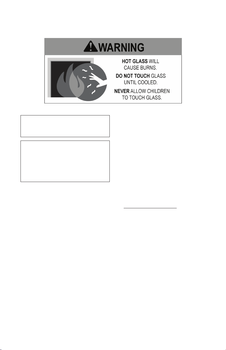
This replace reaches high temperatures. Keep children and adults
away from hot surface to avoid burns or clothing ignition. Fireplace
will remain hot for a time after shutdown. Allow surface to cool before touching.
116237-01M 3
www.fmiproducts.com
SAFETY
Continued
Carefully supervise young children when they are in the room
with replace.
Keep the area around your
replace clear of combustible
materials, gasoline and other
ammable vapor or liquids. Do
not run replace where these
are used or stored.
1. For propane/LP replace, do not place
propane/LP supply tank(s) inside any
structure. Locate propane/LP supply
tank(s) outdoors. To prevent performance
problems, do not use propane/LP fuel tank
of less than 100 lb. capacity.
2. If you smell gas
• shut off gas supply
• do not try to light any appliance
• do not touch any electrical switch; do
not use any phone in your building
• immediately call your gas supplier from
a neighbor’s phone. Follow the gas
supplier's instructions
• if you cannot reach you gas supplier,
call the re department.
3. Never install the replace
• in a recreational vehicle
• in windy or drafty areas where curtains
or other combustible (flammable)
objects can make contact with the
replace front
• in high trafc areas
4. Turn fireplace off and let cool before
servicing, installing or repairing. Only a
qualied service person should install,
service or repair this replace. Have replace inspected annually by a qualied
service person.
5. You must keep control compartments,
burners and circulating air passages
clean. More frequent cleaning may be
needed due to excessive lint and dust
from carpeting, bedding material, etc.
Turn off the gas valve and pilot light before
cleaning replace.
6. Have venting system inspected annually by
a qualied service person. If needed, have
venting system cleaned or repaired. See
Cleaning and Maintenance, page 30.
7. Do not use any solid fuels (wood, coal,
paper, cardboard, etc.) in this replace.
Use only the gas type indicated on replace nameplate.
8. This appliance, when installed, must be
electrically grounded in accordance with
local codes or, in the absence of local
codes, with the National Electrical Code,
ANSI/NFPA 70.
9. Do not use replace if any part has been
exposed to or under water. Immediately
call a qualied service person to arrange
for replacement of the unit.
10. Do not operate replace if any log is
broken.
11. Do not operate replace with glass door
removed, cracked or broken.
12. Provide adequate clearances around air
openings.
www.fmiproducts.com
116237-01M4
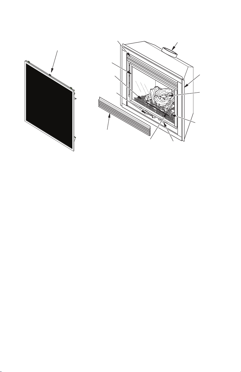
PRODUCT IDENTIFICATION
Screen Door
(VCC42 Series)
Figure 1 - Direct-Vent Fireplace with Millivolt Ignition
Upper Louver Panel
(VC42 Series)
Glass Door
Assembly
Lava Rock
Electronic
Control Valve
Lower Louver Panel
(VC42 Series)
LOCAL CODES
Install and use replace with care. Follow all
local codes. In the absence to local codes,
use the current National Fuel Gas Code ANSI
Z223.1/NFPA 54* (USA).
Flue Collar
Nailing
Flange
Log Set
Burner
Assembly
Glowing
Embers
*Available from:
American National Standards Institute, Inc.
National Fire Protection Association, Inc.
Switch Bracket for Optional
Remote and Blower
1430 Broadway
New York, NY 10018
Batterymarch Park
Quincy, MA 02269
PRODUCT FEATURES
These are a few facts that can help you un-
derstand and enjoy your direct-vent replace:
• The venting system may be routed to the
outside of your home in several ways. It
may vent through the roof (vertical) or it
may vent to an outside/exterior wall (horizontal). The vent pipe installation is very
important to allow for proper operation.
You must follow the venting instructions
very carefully for either vertical or horizontal
applications.
• This replace may be installed in any room
of your house provided all local codes and
these installation instructions are followed.
116237-01M 5
www.fmiproducts.com
• The blower requires electricity. If you plan
to install the blower at a later date, do not
forget to wire the outlet at the bottom of the
replace when framing.
• Each time you turn on your replace, you
may notice some amount of condensation
on the inside of the replace glass. This
is normal and will disappear after 10-20
minutes of operation.
• Your direct-vent gas fireplace system
(replace and venting) is a balanced and
sealed gas operating unit. It requires ap-
proximately 10-20 minutes of operating
time before the ame pattern stabilizes.
D
RW
FW
PRE-INSTALLATION PREPARATION
LOCATION AND SPACE
REQUIREMENTS
Determine the safest and most efcient location for your FMI PRODUCTS, LLC direct-vent
replace. Make sure that rafters and wall
studs are not in the way of the venting system.
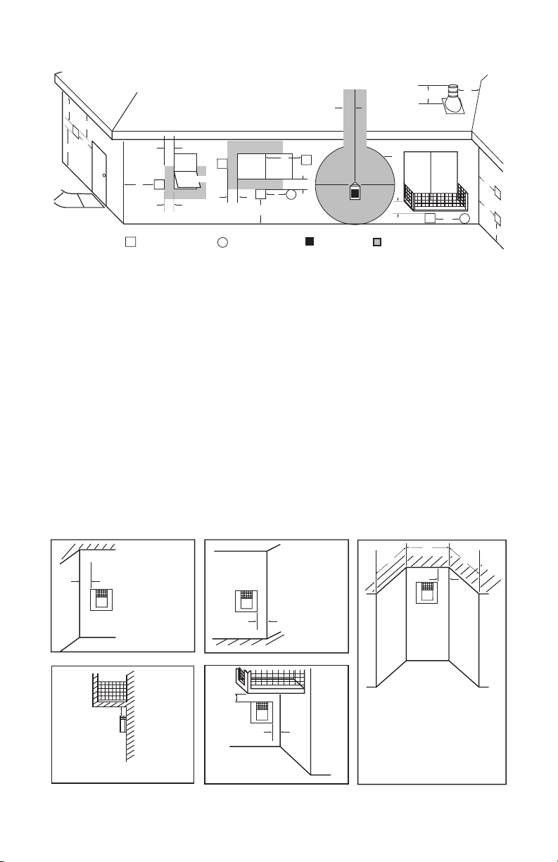
Choose a location where the heat output is
not affected by drafts, air conditioning ducts,
windows or doors. Figure 2 shows some common locations. Be aware of all restrictions and
precautions before deciding the exact location
for your replace and termination cap.
When deciding the location of your replace,
follow these rules:
• Do not connect this replace venting to a
chimney ue serving a separate solid-fuel
burning replace or appliance.
• Due to high temperatures, do not locate this
replace in high trafc areas, windy or drafty
areas or near furniture or draperies.
• Proper clearances must be maintained.
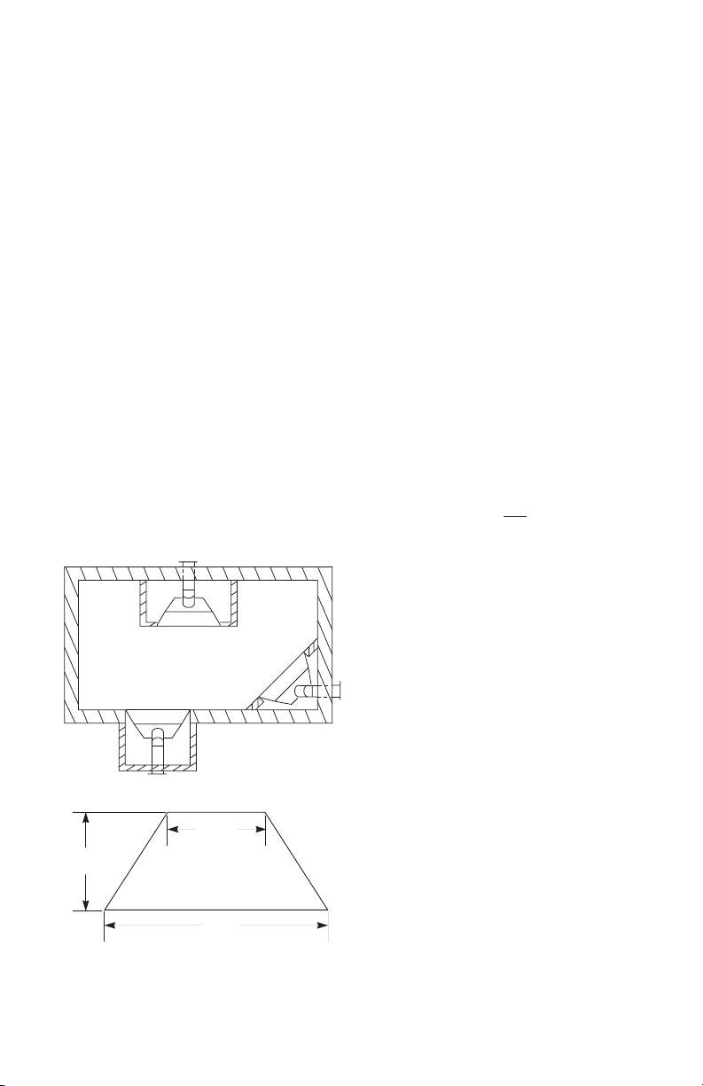
• If your replace is to be installed directly on
carpeting, vinyl tile or any combustible material other than wood, it must be installed on a
metal or wood panel extending the full width
and depth of the replace. See Figure 3.
Flush with a wall
Through exterior wall
enclosed in a chase
Corner
installation
Figure 2 - Common Fireplace Locations
36 1/4"
23 1/4"
48"
Figure 3 - Fireplace Bottom Dimensions
www.fmiproducts.com
• Your replace is designed to be used in
zero clearance installations. Wall or framing
material can be placed directly against any
exterior surface on the back, sides or top of
your replace, except where standoff spacers are integrally attached. If standoff spacers are attached to your replace, these
spacers can be placed directly against wall
or framing material. See framing details on
page 7.
• If you plan on installing a television or entertainment center recessed above your re-
place, it is recommended that you maintain
a minimum 18" above top of louver opening.
• When locating termination cap, it is impor-
tant to observe the minimum clearances
shown in Figure 7, page 8.
• If recessing into a wall, you can avoid extra
framing by positioning your replace against
an already existing framing member.
• Do not recess termination cap into a wall
or siding.
• You may paint the termination cap with
450º F (232º C) heat-resistant paint to
coordinate with the exterior nish.
• There must not be any obstruction such
as bushes, garden sheds, fences, decks
or utility buildings within 24" from the front
of the termination cap.
• Do not locate termination cap where excessive snow or ice build up may occur.
Be sure to clear vent termination area after
snow falls to prevent accidental blockage
of venting system. When using snow
blowers, do not direct snow towards vent
termination area.
CLEARANCES
Minimum clearances to combustibles for the
replace are as follows:
*Back and sides 0"
Perpendicular walls 6"
Floor 0"
Ceiling to louver opening 42"
Front 36"
Top of Standoffs 0"
Vent (See venting instruc-
tions for specic venting clearances.)
Combustible material with a maximum thick-
ness of 5/8" may be ush with the top front
of replace.
* For back and sides of replace, do not pack
with insulation or other materials. 0" clear-
ance to combustible materials are for framing
purpose only.
116237-01M6

A
B
E
F
G
H
D
C
Nailing Tabs
C
B
A
D
E
F
G
Top of Louver
Opening
3
2
1
4
5
6
7
Wall
PRE-INSTALLATION PREPARATION
Continued
NOTICE: This replace is intended for use as supplemental
heat. Use this replace along with
your primary heating system. Do
not install this replace as your
primary heat source. If you have a
central heating system, you may
run system’s circulating blower
while using replace. This will
help circulate the heat throughout the house. In the event of a
power outage, you can use this
replace as a heat source.
FRAMING AND FINISHING
Figure 4, page 7, shows typical framing of this
replace. Figure 5, page 7, shows framing for
corner installation. All minimum clearances
must be met.
For available accessories for this replace,
see Accessories on page 35. If you are using
a separate combustible mantel piece, refer to
Figure 6, page 7, for proper installation height.
You can install noncombustible mantels at any
height above the replace.
Note: Noncombustible mantels may discolor!
21 5/8"
13 1/2"
58 1/2"
41 5/8"
16 3/4"
48"
48 1/4"
Nailing
Tabs
81 1/2"
Figure 5 - Framing Clearances for Corner
Installation
40 1/8"
48 1/4"
23" Horizontal Vent
26 1/2" Vertical Vent
Figure 4 - Framing Clearances for
Installation Against an Exterior Wall
116237-01M 7
www.fmiproducts.com
Figure 6 - Clearances for Combustible
Mantel
Ref.
Depth Ref.
1 14" A 16"
2 12" B 14"
3 10" C 12"
4 8" D 10"
5 6" E 8"
6 4" F 6"
7 2" G 4"
Mantels
Mantel from
Top of Louver
Opening
LOCATION OF TERMINATION CAP
D
E
V
B
L
A = clearance above grade, veranda, porch, deck, or
balcony [*12" (30.5 cm) minimum]
B = clearance to window or door that may be opened
[6" (15 cm) min. for 10,000 Btu or less; 9" (23 cm) in US
if between 10,000 and 50,000, 12" (30 cm) in Canada
if between 10,000 and 100,000; 12" (30 cm) in US if
greater than 50,000, 36" (91 cm) in Canada if greater
than 100,000]
C = clearance to permanently closed window
[minimum 12" (30.5 cm) recommended to prevent
condensation on window]
D = vertical clearance to ventilated soffit located above the
terminal within a horizontal distance of 24" (61 cm) from
the center-line of the terminal [18" (45.7 cm) minimum]
E = clearance to unventilated soffit [12" (30.5 cm) minimum]
F = clearance to outside corner (see below)
G = clearance to inside corner (see below)
H = *not to be installed above a meter/regulator assembly
within 36" (91.4 cm) horizontally from the center line
of the regulator
† vent shall not terminate directly above a side-walk or paved driveway which is located between two
single family dwellings and serves both dwellings*
‡ only permitted if veranda, porch, deck or balconey is fully open on a minimum of 2 sides beneath the floor*
* as specified in CAN/CSA B149 (.1 or .2) Installation Codes (1991) for Canada and U.S.A.
Note: Local codes or regulations may require different clearances
Termination Clearances for Buildings with Combustible and Noncombustible Exteriors
Inside Corner
A
A = 6" (15.2 cm)
V
C
F
V
B
TERMINATION CAP
V
Fixed
Closed
Openable
V
Openable
B
AIR SUPPLY INLET
X
B
V
Fixed
Closed
B
J
V
X
A
I = clearance to service regulator vent outlet [*72" (182.9 cm)
minimum]
J = clearance to non-mechanical air supply inlet to building
or the combustion air inlet to any other fireplace
[6" (15 cm) min. for 10,000 Btu or less; 9" (23 cm) in US
if between 10,000 and 50,000, 12" (30 cm) in Canada
if between 10,000 and 100,000; 12" (30 cm) in US if
greater than 50,000, 36" (91 cm) in Canada if greater
than 100,000]
K = clearance to a mechanical air supply inlet [*In Canada,
6 ft. (1.83m) minimum; In US 3 ft. (91 cm) above if within
10 ft. (3 m) horizontally]
L = † clearance above paved side-walk or a paved driveway
located on public property [*84" (213.3 cm) minimum]
M = clearance under veranda, porch, deck
[*12" (30.5 cm) minimum ‡]
N = clearance above a roof shall extend a minimum of
24" (61 cm) above the highest point when it passes
through the roof surface and any other obstruction within
a horizontal distance of 18" (45.7 cm)
Outside Corner Recessed Location
V
B = 6" (15.2 cm)
B
H
I
G
G
GAS METERRESTRICTED AREA
M
(TERMINATION PROHIBITED)
C
N
N
G
V
G
V
K
V
X
A
D
C
E
V
Balcony with No Side Wall
G
V
G = 12" (30.5 cm) minimum clearance
Figure 7 - Minimum Clearances for Termination Cap
Balcony with Perpendicular Side Wall
H
V
J
Combustible &
Noncombustible
H = 24" (61 cm)
J = 20" (50.8 cm)
www.fmiproducts.com
C = Maximum depth of 48" (121.9 cm)
for recessed location
D = Minimum width for back wall of
recessed location Combustible - 38" (965 mm)
Noncombustible - 24" (61 cm)
E = Clearance from corner in
recessed location Combustible - 6" (15.2 cm)
Noncombustible - 2" (5.1 cm)
116237-01M8
VENTING INSTALLATION
NOTICE: Read these instruc-
tions completely before attempting installation.
These models are tested and approved for
use with FMI PRODUCTS, LLC (direct-vent)
pipe components and terminations.
The venting system must terminate on the outside of the structure and can not be attached
to a chimney or ue system serving a separate
solid fuel or gas burning appliance. A direct-vent
appliance must have its own venting system.
DO NOT common vent this appliance.
These models are approved to be vented
either horizontally through an outside wall or
vertically through a roof or chase enclosure
using the following guidelines:
• When venting system terminates horizon-
tally on an outside wall, you may install
a standoff if the termination cap is to be
installed directly on a combustible nish
such as vinyl, wood, stucco, etc.
• Never run the vent downward as this may
cause excessive temperatures which could
cause a re.
• Vent pipe air space clearances to com-
bustibles are 1" on all sides except on the
horizontal sections, which requires 2" clearance from the top of the pipe. Where the
termination cap penetrates a combustible
wall, 1" air space clearance is required.
• Snorkel terminations are required when
minimum clearance to grade cannot be
met (see Figure 16 on page 13).
• Have replace and selected vent compo-
nents on hand to help determine the exact
measurements when elbowing or offsetting.
Always use wall restops when penetrating
walls and restops when penetrating ceilings or attic spaces.
• If using a venting conguration of only
horizontal venting with no vertical run, a
1/4" rise for every 12" of run toward the
termination is required.
• For installation of replace at elevations of
4000 feet or greater, pay special attention
to venting requirement recommendations.
WARNING: Read all instruc-
tions completely and thoroughly
before attempting installation.
Failure to do so could result in
serious injury, property damage
or loss of life.
NOTICE: Failure to follow these in-
structions will void the warranty.
NOTICE: Do not seal termination
cap to vent pipe. Cap must be
removable for vent inspection
and maintenance.
INSTALLATION PRECAUTIONS
• Wear gloves and safety glasses for protection.
• Use extreme caution when using ladders
or when on roof tops.
• Be aware of electrical wiring locations in
walls and ceilings.
The following actions will void the warranty
on your venting system:
• Installation of any damaged venting component.
• Unauthorized modication of the venting
system (Do not cut or alter vent components).
• Installation of any component part not
manufactured or approved by FMI PROD-
UCTS, LLC.
• Installation other than as instructed by
these instructions.
WARNING: This gas replace
and vent assembly must be
vented directly to the outside.
The venting system must NEVER
be attached to a chimney serving a separate solid fuel burning
appliance. Each direct-vent gas
appliance must use a separate
vent system. Do not use common vent systems.
WARNING: Vent pipe air
space clearances to combustibles are 1" on all sides except
on the horizontal sections,
which require 2" clearances
from the top of the pipe. Where
the termination cap penetrates
a combustible wall, 1" air space
clearance is required.
116237-01M 9
www.fmiproducts.com

VENTING INSTALLATION
(Framing
Detail)
11
1
/2"
11
1
/2" Inside Framing
11
1
/2"
8 1/2"
Vent Opening
Combustible Wall
Vent Opening
Noncombustible Wall
INSTALLATION PLANNING
There are two basic types of direct-vent
installation:
• Horizontal Termination
• Vertical Termination
Horizontal Termination Installation
IMPORTANT: Horizontal square terminations
require only inner portion of wall restop. Hori-
zontal installations using round termination
require exterior portion of wall restop (see
Figure 14, page 12).
1. Set replace in its desired location and
determine route your horizontal venting
will take. Do not secure replace until all
venting has been installed. Some installations require sliding replace in and out
of position to make nal venting connections. Figures 14 through 18 on pages 12
through 14 show different congurations
for venting with horizontal termination that
will help you decide which application best
suits your installation. Check to see if wall
studs or roof rafters are in the path of your
desired venting route. If they are, you may
want to adjust location of replace.
2. Direct vent pipe sections and components
are designed with special twist-lock con-
nections.
Twist-Lock Procedure: Female ends of
pipes have locking lugs (indentations).
These lugs will slide straight into match-
ing slots on male ends of adjacent pipes.
Push pipe sections together and twist
one section clockwise approximately one-
quarter turn until sections are fully locked
(see Figure 8). Note: Horizontal runs of
vent must be supported every three feet.
Use wall straps for this purpose.
3. Use a 45° elbow to connect venting system
to replace ue collar. The elbow is designed to be twist-locked onto the ue collar
as described in step 2. IMPORTANT: Do
not attempt to alter the conguration of the
elbow by cutting, twisting, bending, etc.
4. Assemble desired combination of pipe
and elbows to replace ue collar. If there
are long portions of venting run, pre-assembled pipe sections may be installed
as subassemblies for convenience.
Continued
5. Carefully determine location where vent
pipe assembly will penetrate outside
wall. Center of hole should line up with
center line of horizontal vent pipe. Mark
wall for a 11 1/2" x 11 1/2" square hole.
Cut and frame square hole in exterior
wall where vent will be terminated. If wall
being penetrated is constructed of noncombustible material, such as masonry
block or concrete, a 8 1/2" hole with zero
clearance is acceptable (see Figure 9).
Female Locking Lugs
Figure 8 - Vent Pipe Connections
Figure 9 - Vent Opening Requirements
www.fmiproducts.com
Male
Slots
Center of
Hole
116237-01M10
VENTING INSTALLATION
Continued
WARNING: Do not recess
vent termination into any wall.
This will cause a re hazard.
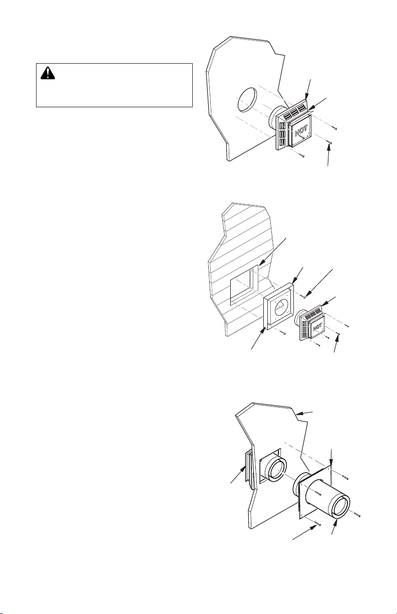
6. Noncombustible Exterior Wall: Position
horizontal vent cap in center of 8 1/2" round
hole and attach to exterior wall with four
wood screws provided. Before attaching
vent cap to exterior wall, run a bead of
non-hardening mastic (pliable sealant)
around outside edges to make a seal be-
tween it and outside wall. Note: Four wood
screws provided should be replaced with
appropriate fasteners for stucco, brick,
concrete or other types of sidings.
Combustible Exterior Wall: For vinyl
siding, stucco or wood exteriors, a siding
standoff may be installed between vent
cap and exterior wall. Siding standoff
prevents excessive heat from damaging
siding materials. Siding material must be
cut to accommodate standoff. Bolt vent
cap to standoff. Apply non-hardening
mastic around outside edge of standoff.
Position standoff/cap assembly in center
of the 11 1/2" square hole and attach to
exterior wall with wood screws provided
(see Figure 11). Siding standoff must sit
ush against exterior fascia material.
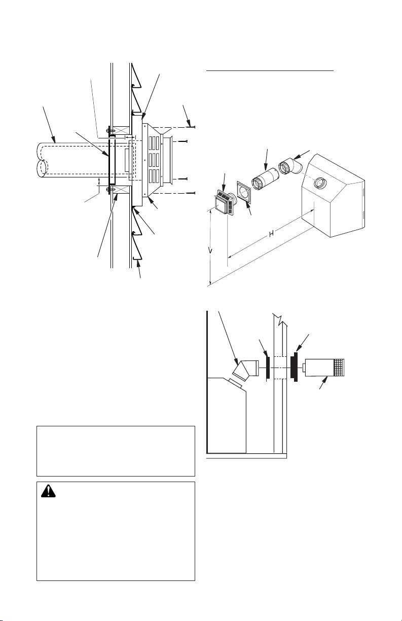
7. Connecting Vent Cap With Horizontal
Vent Pipe: Slide wall restop over the
vent pipe before connecting horizontal
run to vent cap (see Figure 12).
Carefully move replace, with vent as-
sembly attached, toward wall and insert
vent pipe into horizontal termination. Pipe
overlap should be a minimum of 1 1/4" (see
Figure 13, page 12).
Slide wall restop against interior wall
surface and attach with screws provided.
See Figure 13, page 12, for horizontal
termination details.
Place replace into position and shim with
noncombustible material if needed. Nail or
screw side anges to framing to secure
unit in place. IMPORTANT: Make sure re-
place is level before securing. If replace
is not level it will not work properly.
Apply Mastic to
All Four Sides
Vent Cap
Wood Screw
Figure 10 - Installing Horizontal Vent Cap
(Noncombustible Exterior)
Cut Siding Away
to Fit Standoff
Standoff
Apply Mastic to
All Four Sides
Figure 11 - Installing Siding Standoff
(Combustible Exterior Wall)
Vent Cap
(Horizontal
Termination)
Screw
Figure 12 - Connecting Vent Cap with
Horizontal Vent Pipe
Wood
Screw
Vent
Cap
Screws
Interior Wall
Surface
Wall
Firestop
Horizontal
Vent Pipe
116237-01M 11
www.fmiproducts.com
VENTING INSTALLATION
Continued
Minimum Pipe
Overlap 11/4"
Direct-Vent
Pipe
Wall
Firestop
Maintain 1"
Minimum Air
Space Around
Outer Pipe When
Penetrating a Wall
11 1/2" x 11 1/2"
Framed Opening
Exterior Wall with Vinyl Siding
Figure 13 - Typical Horizontal
Termination Cap Mounting with
Additional Siding Standoff Installed
Horizontal Termination Congurations
Figures 14 through 18 show different con-
gurations and alternatives for venting with
horizontal termination. Each gure includes
a chart with critical minimum and maximum
dimensions which MUST be met. IMPORTANT: If using a venting conguration of only
horizontal venting with no vertical run, a 1/4"
rise for every 12" of run toward the termina-
tion is required.
NOTICE: Do not seal termination
cap to vent pipe. Cap must be
removable for vent inspection
and maintenance.
WARNING: Never run vent
downward as this may cause
excessive temperatures which
could cause a re. Operation of
improperly installed and maintained venting system could
result in serious injury, property
damage or loss of life.
Siding Standoff
Screws
High Wind
Termination
Apply
Mastic to
Outside
Edge of
Standoff
GROUND FLOOR INSTALLATION
Recommended Applications:
• Installation using cabinet surrounds
• Through the wall using round or square
termination (up to 12" adjustable pipe)
• NOT FOR CORNER INSTALLATION
Horizontal
High Wind
Square
Termination
45° Elbow
* If installing this replace at altitudes of 4000
feet and above, it is recommended that an
additional vertical height of 6" be added to
the vent system.
Figure 14 - Horizontal Termination
Conguration for Square or Round
Adjustable
Pipe 12" Max.
Wall Firestop
Square Termination
Vertical (V) Horizontal (H)
32 3/4" min. 17" max.
Wall
Firestop
Terminations
45° Elbow
Exterior Portion of
Wall Firestop (Round
Termination Only)
Horizontal
Round
Termination
Round Termination
www.fmiproducts.com
116237-01M12
 Loading...