

Page 1
FMI PRODUCTS, LLC
TSRC TOUCH SCREEN REMOTE CONTROL
INCLUDES MANUAL, THERMOSTAT AND PROGRAMMABLE FEATURES
FOR USE WITH FMI PRODUCTS, LLC MANUFACTURED
"REMOTE READY" GAS HEARTH PRODUCTS
INTRODUCTION
This remote control system was developed to provide a safe, reliable, and user-friendly remote
control system for gas heating appliances or other compatible appliances. The system can
be operated manually from the transmitter.
Review COMMUNICATION SAFETY under TRANSMITTER section and
THERMO SAFETY under REMOTE RECEIVER section. These signal/
temperature safety features shut down the replace system when a potentially unsafe condition exists.
The transmitter operates with (4) AAA 1.5V
batteries that are included. Install the batteries
supplied with the unit into the battery compartment. It is recommended that ALKALINE
batteries always be used for this product. Be
sure the batteries are installed with the (+)
and (-) ends facing the correct direction.
When you start up the remote, if a low battery
signal appears or if they LCD screen does not
illuminate when you touch it, check battery
position and if the batteries are fully charged.
BATTERY
COMPARTMENT
MODE
PROG
SET
FRONT
PROG
MODE
BACK
SET
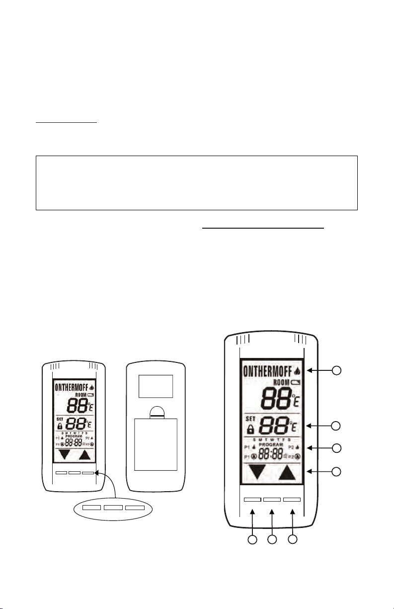
KEY TOUCHSCREEN SETTINGS
1. MODE - Switches the appliance on/
thermo/off.
2. PROGRAM - Turns on and off the program function.
3. SET - Used in different functions to
conrm settings.
4. UP and DOWN - Used to change the
time, set temp, and programming functions.
1
3
2
4
MODE
PROG
SET
Figure 1 - Remote Control Battery
Compartment
2
3
1
Figure 2 - Touchscreen Settings
Page 2
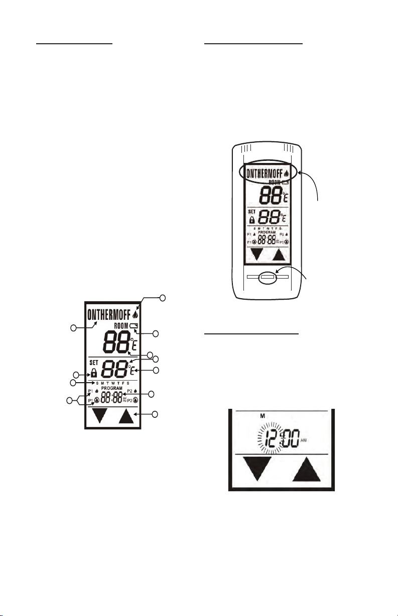
MODE FUNCTION
1
2
3
4
5
6
7
8
9
10
11
MODE
SET
PROG
Mode: Button
Mode: Touch
Portion
1. BATTERY ICON - . Battery power is low.
Replace Batteries in 2 - 4 weeks.
2. ROOM - Indicates CURRENT room
temperature.
3. SET- Indicates desired SET room temperature for THERMO operation.
4. FAHRENHEIT/CELSIUS - Indicates
degrees Fahrenheit or Celsius.
5. FLAME- Indicates burner/valve in operation.
6. MODE – Indicates operation mode of
system.
7. UP and DOWN – These are used to
adjust the Time, Set temperature, and
program functions.
8. TIME and PROGRAM TIME – Indicates
current time or program time setting
when editing program settings.
9. LOCK - Child lock out.
10. PROGRAM ON/OFF – Indicates when
Program 1 (P1) is on or off, and indicates
when Program 2 (P2) is on or off.
11. DAY of WEEK - Indicates current day of
week, or program segment when editing
program settings.
SETTING ºF/ ºC SCALE
The factory setting for temperature is ºF. To
change this setting to ºC, rst press and hold
the UP touch button and the DOWN touch button on the transmitter at the same time. Follow
same procedure to change from ºC back to ºF.
NOTE: When changing between the ºF and
ºC scales, the set temperature defaults to the
lowest temperature (45 ºF, or 6 ºC).
Figure 4 - Settings
SETTING THE CLOCK
1. Press and hold the SET button, or touch
the SET section on the touch screen,
for 5 seconds. The hour section should
begin to ash. (Fig. 5).
2. Use the UP and DOWN touch buttons to
select the hour, then press SET.
Figure 3 - Mode Function
NOTE: Touch anyplace on the screen and
the back light will light up and stay lit for 5
seconds.
To select an operation mode, press the MODE
button or touch the MODE SECTION at the
top of the LCD screen.
• ON turns the appliance ON, the ame
icon will appear.
• THERMO sets the remote to Thermo
mode.
• OFF turns the appliance OFF, the ame
icon will disappear.
www.fmiproducts.com
Figure 5 - Setting the Clock
3. The minutes will be ashing. Use the
UP and DOWN touch buttons to select
the minute, then press SET. (Fig. 5A,
page 3).
126414-01A2
Page 3
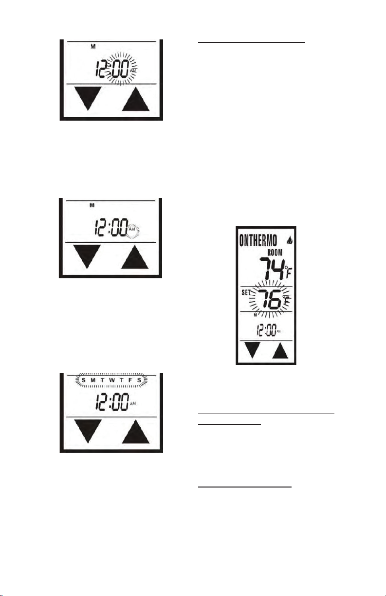
Figure 5A - Setting the Clock
4. The AM PM will be ashing. Use the UP
and DOWN touch buttons to select one
of them, then press SET. (Fig. 5B).
Figure 5B - Setting the Clock
5. One of the days of the week will be ash-
ing (above the clock). Select the correct
day by pressing the UP and DOWN touch
buttons, then press SET. Your time will
automatically be accepted. (Fig. #5C).
THERMOSTAT FUNCTION
This remote control system can be thermostatically controlled when the transmitter is
in the THERMO mode (THERMO must be
displayed on the screen). To set the desired
room temperature, press the MODE button to
place the transmitter into thermo mode, then
press the UP or DOWN touch buttons to select
the desired room temperature. The highest set
temperature is 99 ºF (32 ºC).
NOTE: The thermo feature operates the
appliance whenever the room temperature
varies a certain number of degrees from the
set temperature. This variation is called the
“swing” or temperature differential. This feature lets the appliance turn OFF and ON 2 ºF
(1 ºC) above or below the set temperature of
the room. This is to cushion the number of
times the appliance is turned ON and OFF.
Figure 6 - Setting Thermostat
THERMO UPDATING FEATURE TRANSMITTER
When in thermo mode, the transmitter reads
the ROOM temperature every 2 minutes,
checks the room temperature against the
SET temperature then sends a signal to the
Figure 5C - Setting the Clock
receiver.
PROGRAM FUNCTION
This remote has two program segments: A
weekday segment and a weekend segment.
To enter program mode, push the PROG
button or touch the program portion of the
touch screen the word PROGRAM will appear
above the display time to indicate program
operation is active.
126414-01A 3
www.fmiproducts.com
Page 4
THE FACTORY PRESETS ARE:
WEEKDAYS
''P1 ON'' 5:00 AM at 72ºF
''P1 OFF'' 9:00 AM
''P2 ON'' 4:00 PM at 72ºF
''P2 OFF'' 10:00 PM
4
1
5
2
WEEKDAYS
''P1 ON'' 6:00 AM at 72ºF
''P1 OFF'' 10:00 AM
''P2 ON'' 5:00 PM at 72ºF
''P2 OFF'' 10:00 PM
The user may override the program function
by putting the remote in manual ON mode.
When the user turns the remote back to OFF
mode, the remote will resume regular program
mode (the word PROGRAM is above the
display time). To turn the program function
OFF, touch the program portion on the touch
screen or press the PROG button. The word
PROGRAM will disappear from the LCD
screen.
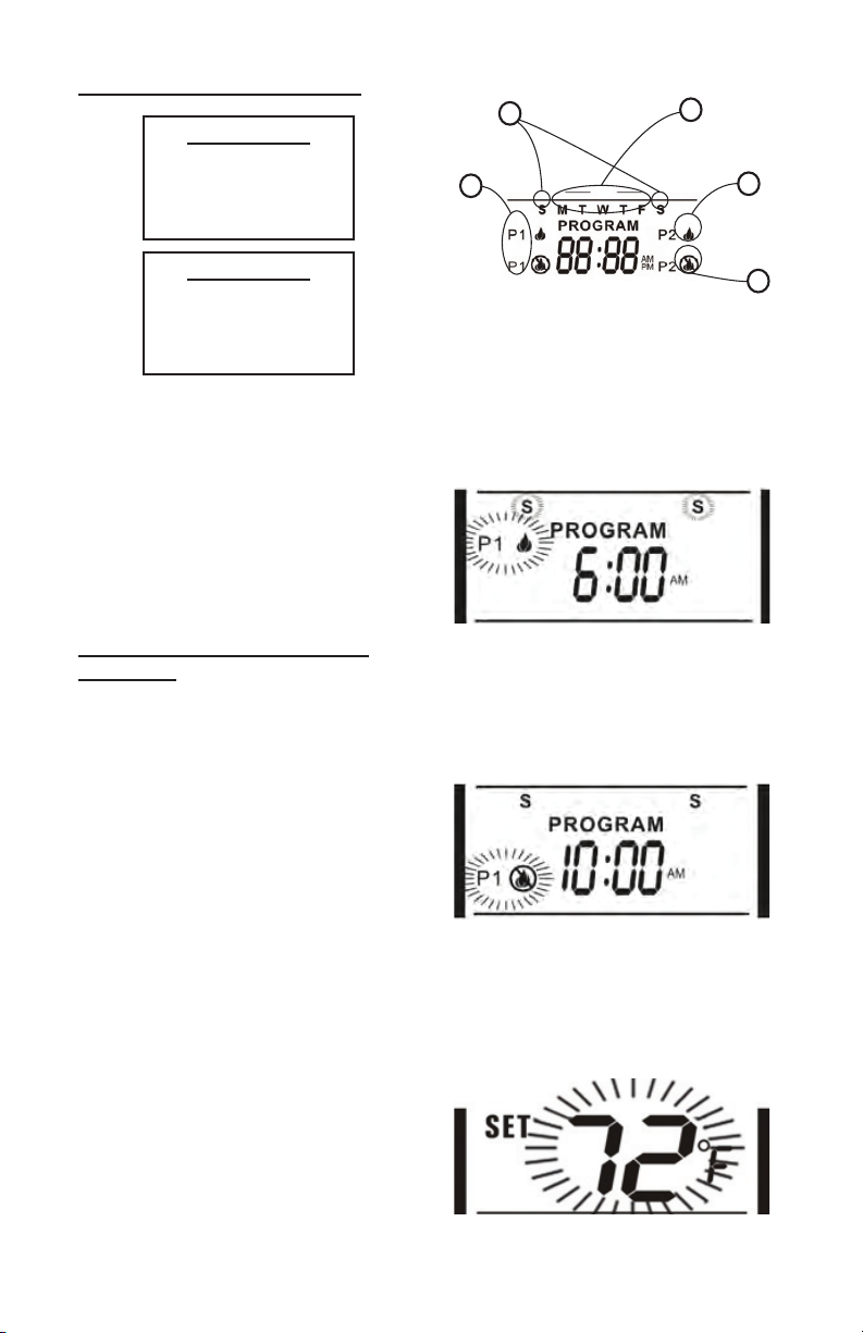
EDITING FACTORY PROGRAM
SETTINGS
1. Program Segment: Program 1, or Program 2 (other side of LCD screen).
2. Flame On: Time when you want your
appliance to turn ON.
3. Flame Off: Time when you want your
appliance to turn OFF.
4. Weekend Segment: Saturday and
Sunday.
5. Weekday Segment: Monday through
Friday.
NOTE: P1 CAN ONLY BE SET FROM
12:00AM to 12:00PM
P2 CAN ONLY BE SET FROM 12:00PM to
12:00 AM
Press either the PROG button or touch the
Program portion of the touch screen and hold
for 5 seconds, the program section of the LCD
screen will begin to ash.
3
Figure 7 - Editing Factory Program
• P1 ON and “S S” (Weekend Segment)
should be ashing. Select the time you
want your appliance to turn on by using
the UP and DOWN touch buttons. Then
press SET (See Fig. #8).
Figure 8
• P1 OFF will be ashing. Select the time
you want your appliance to turn off. Then
press SET (See Fig. #9).
Figure 9
• The set temperature will begin to ash.
Use the UP and DOWN touch buttons to
select a temperature for P1, then press
SET (See Fig. #10).
www.fmiproducts.com
Figure 10
126414-01A4
Page 5

• Now the P2 ON will begin to ash. Select
the time you want your appliance to turn
on by using the UP and DOWN touch
buttons. Then press SET. (See Fig. #11).
Figure 11
• P2 OFF will be ashing. Select a time
you want your appliance to turn off. Then
press SET (See Fig. #12).
• The set temperature will begin to ash.
Use the UP and DOWN touch buttons
to select a temperature for P2, then
press SET.
Figure 12
• “MTWTF” (Weekday Segment) will
replace “S S”. P1 ON will be ashing.
Repeat the above steps to set the ON
and OFF times and set temperatures for
weekdays (See Fig. #13).
SETTING TEMPERATURE SWING
(Temperature differential)
The Thermo Mode on the transmitter operates
the appliance whenever the room temperature
varies a certain number of degrees from the
set temperature. This variation is called the
“SWING” or TEMPERATURE DIFFERENTIAL. The factory preset swing temperature
is 2 ºF (1 ºC). To change the “Swing Setting:”
• Press the SET button and the DOWN
touch button simultaneously to display
the current “swing” setting in the set temp
frame. The letter “S” will display in the
room temp frame on the LCD screen.
• Press the UP or DOWN touch button to
adjust the “SWING” temperature (1º-3º
F) (1º-2º C).
• To store the “swing” setting press the
SET button, and the new “swing” setting
will be automatically programmed.
Figure 14 - Setting Temperature Swing
Figure 13
126414-01A 5
www.fmiproducts.com
Page 6

COMMUNICATION - SAFETY
This remote control has a COMMUNICATION
–SAFETY function built into its software. It
provides an extra margin of safety when the
Transmitter is out of the normal 20-foot operating range of the receiver.
At all times and in all OPERATING MODES,
the transmitter sends an RF signal every 15
minutes, to the receiver, indicating that the
transmitter is within the normal operating
range of 20 feet. Should the receiver NOT
receive a transmitter signal every 15 minutes,
the receiver will begin a 2-hour (120 minute)
countdown timing function. If during this
2-hour period, the receiver does not receive
a signal from the transmitter, the receiver will
shut down the appliance being controlled
by the receiver. The receiver will then emit
a series of rapid “beeps” for a period of 10
seconds. Then after 10 seconds of rapid beeping, the receiver will continue to emit a single
“beep” every 4 seconds until a transmitter
MODE button is pressed to reset the receiver.
MODE
PROG
SET
MODE
Figure 15 - Communication-Safety
CHILDPROOF ''LOCK-OUT''
This remote control includes a CHILDPROOF
“LOCK-OUT” feature that allows the user to
“LOCK-OUT” operation of the appliance from
the TRANSMITTER.
• To activate the “LOCK-OUT” feature, press
and hold the UP touch button and the SET
button together for 5 seconds. The “LOCK”
icon will appear on the LCD screen.
• To disengage the “LOCK-OUT”, press
and hold the UP touch button and the
SET button together for 5 seconds or
more, the “LOCK” icon will disappear
from the LCD screen and the transmitter will return to its normal operating
condition.
• When the Transmitter is in “LOCK-OUT”
mode, programmed functions will go on
without interruption; Only manual functions are prevented.
www.fmiproducts.com
Figure 16 - Childproof ''Lock-out''
RECEIVER
Install the 4 AA-size batteries supplied with
the unit. It is recommended that ALKALINE
batteries always be used for this product. Be
sure the batteries are installed with the (+) and
(-) ends facing the correct direction.
The remote receiver has a 3-position slide
switch for selecting the mode of operation
ON/REMOTE/OFF
• ON: will manually turn ON the appliance.
• REMOTE: will allow use of handheld
transmitter. If the system does not respond to the transmitter on initial use,
check the battery positions in the remote.
If that does not work, see the LEARNING
TRANSMITTER TO RECEIVER section.
• OFF: will disable the remote receiver.
• It is suggested that the slide switch be
placed in the OFF position if you will be
away from your home for an extended
period of time.
Requires 4-AA 1.5V
alkaline batteries
Learning
button
Slid e
Switch
ON
REMOTE
OFF
Figure 17 - Installing Batteries
LEARN
Remote Receiver
NO
REMOTE
OFF
Battery cover slides on/o
126414-01A6
Page 7

WARNING: This remote control
WALL
system must be installed exactly
as outlined in these instructions.
Read all instructions completely
before attempting installation. Follow instructions carefully during
installation.Anymodicationsof
this remote control or any of its
components will void the warranty
andmayposearehazard.
Do not connect any gas valve
or electronic module directly to
110-120VAC power. Consult gas
appliance manufacturer’s instructions and wiring schematics for
proper placement of all wires. All
electronic modules are to be wired
tomanufacturer’sspecications.
The following wiring diagrams
are for illustration purpose only.
Follow instructions from manufacturer of gas valve and/or electronic module for correct wiring
procedures. Improper installation
of electric components can cause
damage to electronic module, gas
valve and remote receiver.
INSTALLATION
The remote receiver can be either wall-mounted in a standard plastic switch box (not metal)
or placed on or near the replace hearth.
Preferably, the remote receiver should be
wall-mounted in a plastic switch box, as this
will protect its electronic components from
the heat produced by the gas appliance. The
remote receiver should be kept away from
temperatures exceeding 130º F. Battery life
is also signicantly shortened if batteries are
exposed to temperatures 130ºF or higher.
Before installation make sure the remote
receiver slide switch is in the OFF position.
After installation be sure that the slide switch
is moved to the REMOTE position.
MOUNTING REMOTE RECEIVER
WALL MOUNT
When wall mounting the remote receiver, longer
wires (not included) are required to connect to
the gas valve or electronic module.
These wires must: Be at least 18 Gauge (AWG),
no longer than 20-feet and have no splices.
Position the receiver as shown in diagram to
the left with lower tab on cover plate inserted
into groove of receiver (Make sure LEARN
hole on cover plate properly aligns with remote receiver). Pull receiver up and snap into
top tab of cover plate.
Cover Plate
(Rear View)
Remote Receiver
Figure 18 - Mounting Receiver on Switch
Position the cover plate so the word ON is
facing up; then, install the remote receiver
into the plastic switch-box using the two long
screws provided. Push the white button over
the receiver slide switch.
Receiver
Slide
Button
Figure 19 - Mounting Receiver in Switch
LEARN
.
ADJ
Cover Plate
ON
R
E
M
O
T
E
OFF
Plate
Plastic Switch Box
Box
126414-01A 7
www.fmiproducts.com
Page 8

HEARTH MOUNT
The remote receiver can be placed on the replace hearth or under the replace behind the
control access panel. Use the wires attached
to the remote receiver to connect to the gas
valve or the electric module (piggyback connectors have both male & female terminals
for exibility).
Be sure that the connectors do not touch
each other or other bare metal surfaces; this
will cause the appliance to turn on. The connectors may be wrapped with electrical tape
to prevent this.
Remote Receiver
Wire Terminals
Receiver
Slide
Button
ADJ.
OFF
REMOTE
LEARN
ON
Piggyback
Connectors
Figure 20 - Receiver Hearth Mounting
WIRING INSTRUCTIONS
A qualied electrician should install the remote
control system.
WIRING MILLIVOLT VALVES
Connect one wire from the remote receiver to
the TH terminal on the gas valve.
Connect the other wire from the remote receiver to the TH/TP terminal on the gas valve.
MILLIVOLT SYSTEM CHECK
• Ensure that the pilot ame is lit.
• Slide the 3-position button on the remote
receiver to the ON position. The main
gas ame (i.e., the re) should ignite.
• Slide the button to OFF. The main ame
should extinguish (the pilot ame will
remain ON).
• Slide the button to REMOTE, then
press the ON button on the transmitter
to change the system to ON. The main
gas ame should ignite.
TERMINAL BLOCK
ON MILLIVOLT
GAS VALVES
TH
TP
REMOTE
RECEIVER
TP
THERMOPILE/
PILOT LIGHT
TH
Figure 21 - Millivolt Wiring Diagram
WIRING ELECTRONIC SPARK
IGNITIONS
The remote control receiver can be connected, in series, to a 24VAC transformer to the TR
(transformer) terminal on the ELECTRONIC
MODULE. Connect the hot wire from the
24VAC transformer to either of the wire terminals on the remote receiver. Connect another
wire between the other receiver wire terminal
and the TH (thermostat) terminal on the
ELECTRONIC MODULE.
ELECTRONIC SPARK SYSTEM
CHECK
• Slide the 3-position button on the remote
receiver to the ON position. The spark
electrode should begin sparking to ignite
the pilot. After the pilot ame is lit, the
main gas valve should open and the
main gas ame should ignite.
• Slide the button to OFF. The main
gas ame and pilot ame should both
extinguish.
• Slide the button to REMOTE, then
press the ON button on the transmitter
to change the system to ON. The spark
electrode should begin sparking to ignite
the pilot. After the pilot is lit, the main
gas valve should open and the main gas
ame should ignite.
ELECTRONIC MODULE
TR
TH
neutral wire
REMOTE
RECEIVER
24VAC
hot wire
110/24VAC
Transformer
120VAC
Figure 22 - Electronic Wiring Diagram
www.fmiproducts.com
126414-01A8
Page 9

GENERAL INFORMATION
LEARNING TRANSMITTER TO RE-
CEIVER
Each transmitter uses a unique security code.
It will be necessary to press the LEARN button on the receiver to accept the transmitter
security code upon initial use, if batteries are
replaced, or if a replacement transmitter is
purchased from your dealer or the factory. In
order for the receiver to accept the transmitter security code, be sure the slide button on
the receiver is in the REMOTE position; the
receiver will not LEARN if the slide switch is in
the ON or OFF position. The LEARN button in
located on the front face of the receiver; inside
the small hole labeled LEARN. Using a small
screwdriver or end of a paperclip gently press
and release the black LEARN button inside
the hole. When you release the LEARN button the receiver will emit an audible “beep”.
After the receiver emits the beep press the
transmitter MODE button and release. The
receiver will emit several beeps indicating
that the transmitter’s code has been accepted
into the receiver.
THERMO SAFETY FEATURE
If the receiver should reach 130ºF, the receiver
will automatically shut down and you’ll hear 3
beeps every 2 seconds. Once the temperature
has dropped between 120ºF and 130ºF, the
user can reactivate the appliance by pressing
the MODE key, but the beeping will continue
until temperatures drop below 120ºF. This
is to tell the user that the receiver needs to
be relocated to reduce temperatures. If this
situation happens, the receiver should be
relocated so it will not reach temperatures in
excess of 130ºF.
TRANSMITTER WALL MOUNT
The transmitter can be placed on a wall using
the mount provided.
Wood - Drill 1/8’’ pilot holes and install with
screws provided.
Plaster/Wallboard - Drill 1/4’’ holes, use a
hammer to tap in the two plastic anchors.
Then install with the screws provided.
Figure 23 - Transmitter Wall Mount
BATTERY LIFE
Life expectancy of the alkaline batteries in the
transmitter and receiver should be at least
12 months.
Check and replace all batteries:
Annually.
When operating range becomes reduced.
When transmissions are not received by the
remote receiver.
If the remote receiver batteries measure less
than 5.3 volts (all four batteries in combination).
If the hand held transmitter batteries measure less than 5.3 volts (all 4 batteries in
combination).
126414-01A 9
www.fmiproducts.com
Page 10

TROUBLESHOOTING
If you encounter problems with your replace
system, the problem may be with either the
replace itself or with the remote. Review the
replace manufacturer’s operation manual to
make sure all connections are properly made.
Then check the operation of the remote in the
following manner:
• Make sure all batteries are correctly
installed in the transmitter and receiver.
Also check that the batteries are fully
charged.
• Check batteries in transmitter to make
sure contacts are touching (+) and (-)
ends of battery. Bend metal contacts in
for tighter t.
• Be sure receiver and transmitter is within
20 to 25-foot operating range.
• Keep receiver from temperatures exceeding 130º F. Battery life will be shortened if exposed to high temperatures.
• If receiver is installed in a tightly enclosed metal surrounding, the operating
distance will be shortened.
• Make sure the hand-held transmitter
and remote receiver are communicating
properly (see LEARNING TRANSMITTER TO RECEIVER section).
FCC REQUIREMENTS
NOTE: THE MANUFACTURER IS NOT
RESPONSIBLE FOR ANY RADIO OR TV
INTERFERENCE CAUSED BY UNAUTHORIZED MODIFICATIONS TO THE EQUIPMENT. SUCH MODIFICATIONS COULD
VOID THE USER’S AUTHORITY TO OPERATE THE EQUIPMENT
TECHNICAL SERVICE
You may have further questions about
installation, operation, or troubleshooting.
If so, contact FMI PRODUCTS, LLC at
1-866-328-4537. When calling please have
your model and serial numbers of your
heater ready.
You can also visit FMI PRODUCTS, LLC's
web site at www.fmiproducts.com.
www.fmiproducts.com
126414-01A10
Page 11

NOTES
_____________________________________________________
______________________________________________________
______________________________________________________
______________________________________________________
______________________________________________________
______________________________________________________
______________________________________________________
______________________________________________________
______________________________________________________
______________________________________________________
______________________________________________________
______________________________________________________
______________________________________________________
_____________________________________________________
______________________________________________________
______________________________________________________
______________________________________________________
______________________________________________________
______________________________________________________
______________________________________________________
______________________________________________________
______________________________________________________
126414-01A 11
www.fmiproducts.com
Page 12

WARRANTY
KEEP THIS WARRANTY
Model (
located on product or identication tag
Serial No. (
located on product or identication tag
Date Purchased __________________________
Keep receipt for warranty verication.
FMI PRODUCTS, LLC LIMITED WARRANTIES
Standard Warranty: FMI PRODUCTS, LLC warrants this new product and any parts thereof to be free from defects
in material and workmanship for a period of one (1) year from the date of rst purchase from an authorized dealer
provided the product has been installed, maintained and operated in accordance with FMI PRODUCTS, LLC’s
warnings and instructions.
For products purchased for commercial, industrial or rental usage, this warranty is limited to 90 days from the date
of rst purchase.
Limited Warranty: FMI PRODUCTS, LLC warrants factory reconditioned products and any parts thereof to be
free from defects in material and workmanship for 30 days from the date of rst purchase from an authorized dealer
provided the product has been installed, maintained and operated in accordance with FMI PRODUCTS, LLC’s
warnings and instructions.
The following terms apply to all of the above warranties:
Always specify model number and serial number when contacting the manufacturer. To make a claim under this
warranty the bill of sale or other proof of purchase must be presented.
This warranty is extended only to the original retail purchaser when purchased from an authorized dealer, and only
when installed by a qualied installer in accordance with all local codes and instructions furnished with this product.
This warranty covers the cost of part(s) required to restore this product to proper operating condition. Warranty parts
must be obtained through authorized dealers of this product and/or FMI PRODUCTS, LLC who will provide original
factory replacement parts. Failure to use original factory replacement parts voids this warranty.
Travel, handling, transportation, diagnostic, material, labor and incidental costs associated with warranty repairs, unless
expressly covered by this warranty, are not reimbursable under this warranty and are the responsibility of the owner.
Excluded from this warranty are products or parts that fail or become damaged due to misuse, accidents, improper
installation, lack of proper maintenance, tampering, or alteration(s).
This is FMI PRODUCTS, LLC’s exclusive warranty, and to the full extent allowed by law; this express warranty excludes any and all other warranties, express or implied, written or verbal and limits the duration of any and all implied
warranties, including warranties of merchantability and tness for a particular purpose to one (1) year on new products
and 30 days on factory reconditioned products from the date of rst purchase. FMI PRODUCTS, LLC makes no
other warranties regarding this product.
FMI PRODUCTS, LLC’s liability is limited to the purchase price of the product, and FMI PRODUCTS, LLC shall not
be liable for any other damages whatsoever under any circumstances including indirect, incidental, or consequential
damages.
Some states do not allow limitations on how long an implied warranty lasts or the exclusion or limitation of incidental
or consequential damages, so the above limitation or exclusion may not apply to you.
This warranty gives you specic legal rights, and you may also have other rights which vary from state to state.
For information about this warranty contact:
Factory Reconditioned Products
Terms Common to All Warranties
) _____________________________
) __________________________
New Products
2701 S. Harbor Blvd.
Santa Ana, CA 92704
1-866-328-4537
www.fmiproducts.com
126414-01
Rev. A
09/12
 Loading...