

Page 1
t
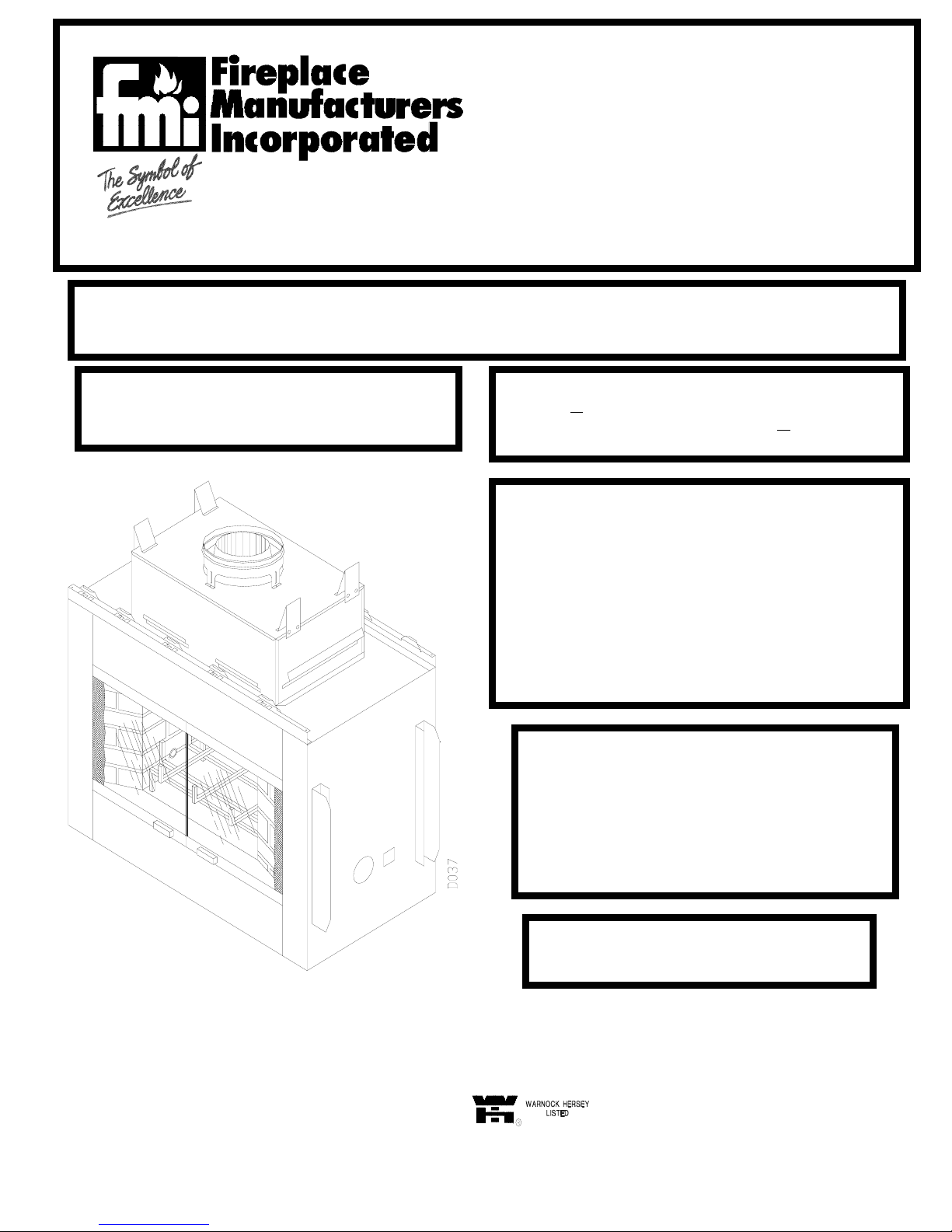
SEE THROUGH / SMOOTH FACE
Wood Burning Fireplace
Models: 368 ST
I368 ST (Fully Insulated)
This book is valuable. In addition to instructing you on how to install and maintain your appliance, it also contains information that
will enable you to obtain replacement parts or optional accessory items when needed. Keep it with your other important papers.
INSTALLATION INSTRUCTIONS
SAVE THIS BOOK
THE WINDSOR
WARNING: ALWAYS LEAVE GLASS DOORS
FULLY OPENED OR FULLY CLOSED WHEN
OPERATING THIS FIREPLACE.
DESA INTERNATIONAL P/N 55200
2701 INDUSTRIAL DRIVE REV B
P.O. BOX 90024 1/00
BOWLING GREEN, KY 42102-9004
www.desatech.com
This Fireplace is approved for use as a Wood Burning
Fireplace or for use with a vented gas log approved to ANS
Z21.60, Z21.84 or RGA 2-72 Standards or for use with a
ven
-free gas log heater approved to ANS Z21.11.2 standard.
FOR YOUR SAFETY
• Do not store or use gasoline or any other flammable
vapors or liquids in the vicinity of this or any other
appliance.
• Due to high temperatures, the appliance should be
located out of traffic and away from furniture and
draperies.
• Do not place clothing or other flammable materials on or
near the appliance.
• NEVER leave children unattended when a fire is burning
in the fireplace.
WARNING
IMPROPER INSTALLATION, ADJUSTMENT,
ALTERATION, SERVICE OR MAINTENANCE CAN
CAUSE INJURY, PROPERTY DAMAGE, OR LOSS
OF LIFE. REFER TO THIS MANUAL FOR
ASSISTANCE OR ADDITIONAL INFORMATION.
CONSULT A QUALIFIED INSTALLER OR LOCAL
DISTRIBUTOR.
CHECK LOCAL CODES BEFORE
INSTALLING THIS FIREPLACE
Page 2
CONTENTS
1. INTRODUCTION PG. 2
2. SELECTING PG. 2,3
3. CLEARANCES PG. 3
4. FRAMING PG. 3, 4
5. HEARTH EXTENSION PG. 4,5
6. OUTSIDE AIR KIT INSTALLATION PG. 5
7. GAS LINE INSTALLATION PG. 5,6
8. CHIMNEY PIPE INSTALLATION PG. 6-8
9. FINISHING YOUR SYSTEM PG. 8,9
10. TERMINATION PG. 10
11. OPERATING GUIDELINES & PG. 11,12
MAINTENANCE INSTRUCTION
12. TECHNICAL SERVICE PG. 12
13. REPLACEMENT & PG. 13
ACCESSORY PARTS
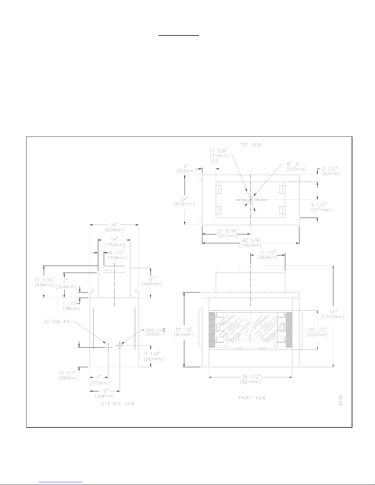
Figure 1
1
Page 3
INTRODUCTION
Model 368ST series is a wood burning fireplace intended and
approved for installation in either residential homes or buildings
of standard construction.
This model fireplace is not for use in mobile homes.
This fireplace system requires the utilization of an FMI 8”
double wall, snap-lock flue pipe system.
BE SURE TO CHECK WITH YOUR LOCAL BUILDING
CODES FOR AREA REQUIREMENTS BEFORE
INSTALLING THIS FIREPLACE.
The model’s serial number and any other specific rating
information may be found on the unit in the WARNOCK
HERSEY RATING PLATE located at the interior of the
fireplace’s opening.
BEFORE YOU BEGIN:
Before beginning the installation of your fireplace read these
instructions through completely. This FMI fireplace and its
approved components are safe when installed according to this
installation manual and operated as recommended by FMI.
Unless you use FMI approved components tested for this
fireplace, YOU MAY CAUSE A FIRE HAZARD.
The FMI warranty will be voided by, and FMI disclaims any
responsibility for the following actions:
A) Modification of the fireplace, doors, blowers, fans, air inlet
system or damper control.
B) Use of any component part not manufactured or approved
by FMI in combination with an FMI fireplace system.
PROPER INSTALLATION is the most important step in
ensuring safe and continuous operation of this fireplace.
Consult the local building codes as to the particular
requirements concerned with the installation of all factory built
fireplaces. Although grounding may not be required by code,
the manufacturer recommends it.
CAUTION: THE STRUCTURAL INTEGRITY OF THE MOBILE
HOME FLOOR, WALL AND CEILING/ROOF MUST BE
MAINTAINED.
WARNING: DO NOT INSTALL A FIREPLACE
INSERT IN THIS FIREBOX UNLESS THE
MANUFACTURER’S INSTRUCTIONS WITH THE
INSERT SPECIFICALLY STATE THIS FIREBOX HAS
BEEN TESTED FOR USE WITH THE INSERT.
This wood burning fireplace complies with UL 127 as a
FACTORY BUILT FIREPLACE.
NOTE:
A qualified installer familiar with fireplaces should do
installation and repair. The fireplace and chimney system
should be inspected and cleaned before use, and periodically
thereafter especially during heating season to prevent the
excessive build-up of soot and creosote and to ensure a safe
operating system.
THIS FIREPLACE IS NOT INTENDED TO BE USED AS A
PRIMARY SOURCE OF HEAT. USE FOR SUPPLEMENTAL
HEAT ONLY.
SELECTING LOCATION
To determine the safest and most efficient location for your
fireplace, you must take into consideration the following
guidelines:
1. The location must allow for all the proper clearances, (See
Figure 2).
2. Consider a location where the heat output would not be
affected by drafts, air conditioning ducts, windows or doors.
3. A location that avoids the cutting of joists or roof rafters will
make installation easier.
4. An outside air kit is included with this fireplace. Accessibility
to outside combustion air must be considered. This can also
be achieved through a vented crawl space in some cases, for
more details refer to section on outside air kit installation.
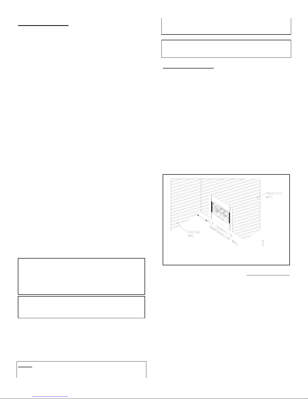
FIGURE 2 shows a plan view of common locations.
Figure 2
The typical installation for a 368ST is a projected installation,
which allows you to extend the fireplace any distance into the
room. A projection may be ideal for a new addition on an
existing finished wall.
2
Page 4
IN SELECTING A LOCATION, THE FOLLOWING
g
PRECAUTIONS MUST BE OBSERVED:
1. Do not connect this fireplace to a chimney system other than
an FMI chimney system.
2. Install in an area providing ventilation and adequate
combustion air.
3. Due to high temperatures, do not locate this fireplace in high
traffic areas or near furniture and draperies.
4. Provide adequate clearances around air openings into the
combustion chamber. NEVER obstruct the front opening of the
fireplace or the flow of combustion and ventilation air.
5. Do not locate in or near an area where gasoline or other
flammable liquids may be stored. The fireplace area must be
kept clear and free from combustible material.
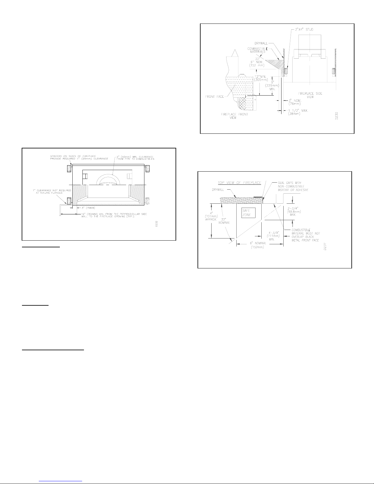
Figure 3
CLEARANCES
MINIMUM CLEARANCES TO COMBUSTIBLE ARE:
BACK:...................................................1” MIN.
PERPENDICULAR SIDE WALL:..................12” MIN.
CHIMNEY OUTER PIPE SURFACES:............2” MIN.
BOTTOM OF FIREPLACE TO FLOOR:...........0” MIN.
(See step 2 under Installing the Fireplace section)
CAUTION:
INSULATION OR ANY OTHER MATERIAL. DO NOT
OBSTRUCT EFFECTIVE OPENING OF FIREPLACE WITH
ANY TYPE OF FACING MATERIAL. COMBUSTIBLE
MATERIAL MUST NOT BE IN CONTACT WITH THE FRONT
FACE OF THE FIREPLACE.
MANTEL CLEARANCES
Woodwork, such as wood trims, mantels, and other
combustible materials, should not be placed within 9 inches of
the effective opening of this fireplace
DO NOT BLOCK REQUIRED AIR SPACES WITH
. The effective
opening is considered the opening where actual heat
output may occur.
Combustible material above and projecting more than 11/2 inches from the fireplace front face, (see figure 4),
should not be placed less than 12 inches from the
effective opening of the fireplace (ref; NFPA std. 7-
3.3.3).
ure 4
Fi
Mantels or any other combustible material also may come up to
the side periphery of the black metal face to the fireplace, just
as long as the projection from the front face falls within the
Figure 5
limits shown in Figure 5.
INSTALLING THE FIREPLACE
STEP 1: Construct framing using dimensions shown in figure
6,8, and 9, depending on your particular installation.
STEP 2: If the fireplace is to be installed directly on carpeting,
tile (other than ceramic), or any combustible material other
than wood flooring; the fireplace must be installed upon a metal
or wood panel extending the full width and depth of the
fireplace.
STEP 3: Set the fireplace directly in front of this opening and
slide the unit back until the mounting flanges touch the side
framing.
STEP 4: Check the level of the fireplace and shim with sheet
metal if necessary.
STEP 5: Before securing fireplace to prepared framing, the
ember protector, (provided), must be placed between hearth
extensions, (not supplied), and bottom front edge of the
fireplace to protect against glowing embers (see Figure 7). If
the fireplace is to be installed on a raised platform, a “Z-type”
ember protector, (not supplied), must be fabricated to fit your
required platform height, (see Figure 8). The ember protector
is made of (26-28ga) galvanized sheet metal to prevent
collision.
STEP 6: Secure the fireplace to the framing through the
flanges located on the sides on the fireplace with 8-penny nails.
3
Page 5
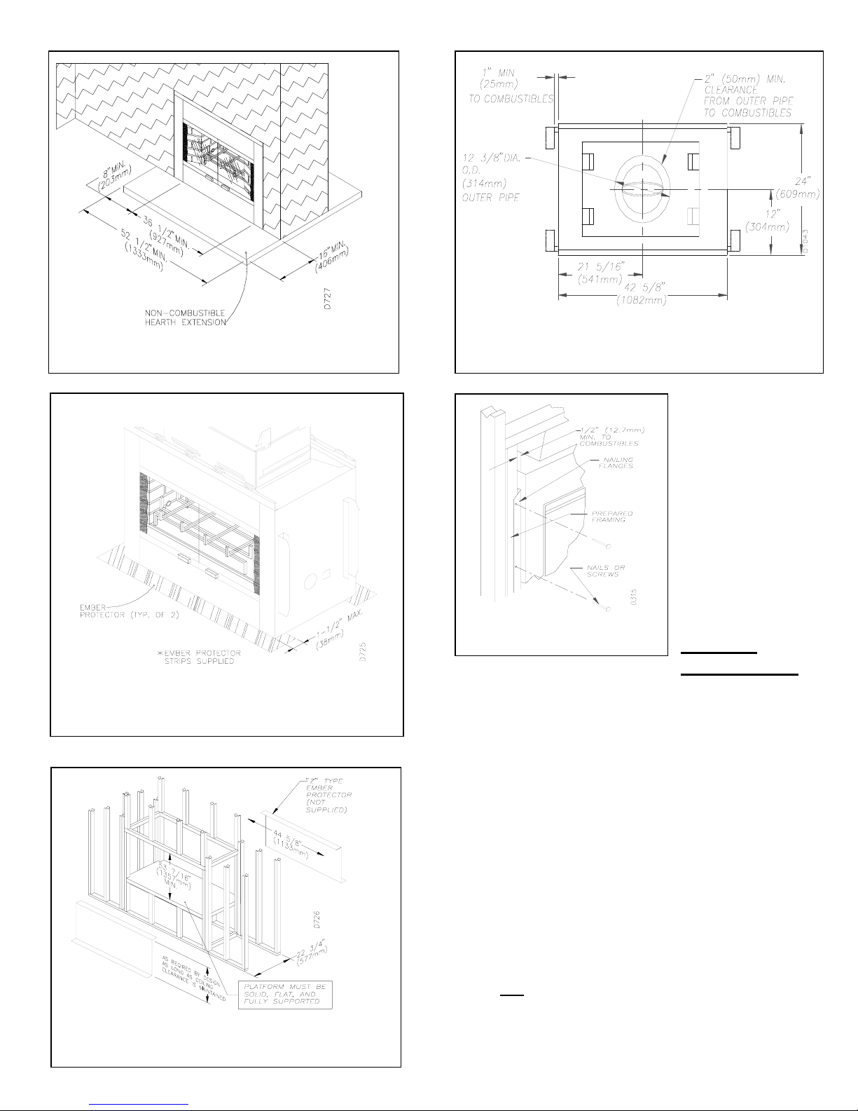
Figure 6
Figure9
Figure 7
Proceed to secure
fireplace to prepared
framing at nailing
flanges located at the
sides of the fireplace
sides shown in Figure
10.
Figure 10
HEARTH
EXTENSIONS
A hearth extension is required to protect combustible floor
surrounding the fireplace. You may obtain kit No. HE-368ST
(see accessories on page 13) or you may fabricated your own
per the dimensions shown on Figure 6.
The hearth extension must project 16 inches minimum to the
front and 8 inches minimum beyond each side of the fireplace
opening, (See Figure 6).
If a hearth extension is to be field constructed, it must be made
of non-combustible, inorganic material having an effective
thermal conductivity “K” of 0.84 BTU In/Ft2 Hr.F or less at 1.0
inch thickness.
Thermal conductivity “K” of materials can be obtained from the
manufacturer.
The minimum required thickness for any material could be
obtained from the manufacturer or supplier of the noncombustible material. For example, if the material selected has
a “K” factor of 0.25 such as glass fiber, the following formula
would apply:
0.25
0.84
x 1.0 inch = 0.30 Thickness required
Figure 8
4
Page 6

.
Figure 11
Place ember strips (supplied with fireplace) approximately ½”
under bottom front face of fireplace or if using a raised platform
of hearth, a “Z” type metal strip must be constructed (see figure
8 & 11).
Fasten hearth extension to the floor to prevent shifting and seal
gap between the fireplace frame and hearth extension with a
non-combustible mortar or adhesive.
OUTSIDE AIR KIT INSTALLATION
The outside air kit must be installed during the rough framing of
the fireplace due to the nature of its location. Outside
combustion air can be accessed through an exterior wall or a
vented crawl space (see Figure 12).
Figure 12
CAUTION: AIR INLET DUCTS MUST NOT TERMINATE IN
ATTIC SPACE OR GARAGE.
Avoid installing outside air eyebrow in areas where inlet
opening may be blocked by snow, bushes or other obstacles.
It should also be located beyond the reach of children.
The maximum height for the air inlet above platform of fireplace
is within 3 feet below the termination flue gas outlet.
For further details on the installation of the outside air kit,
please refer to the instructions included with the air kit. For
operating instructions, please refer to your owner’s manual.
GAS LINE INSTALLATION
GAS LINE HOOK-UP SHOULD BE DONE BY YOUR GAS
SUPPLIER OR A QUALIFIED SERVICE PERSON.
NOTE: BEFORE YOU PROCEED, MAKE SURE YOUR GAS
SUPPLY IS OFF.
A gas line may be installed for the purpose of installing a
decorative gas appliance available through your local
distributor. Use only 1/2-inch black iron pipe and appropriate
fittings. When installing a gas line, a shut-off valve designed
for installation outside the appliance is recommended.
STEP 1: To install, remove the knockout indentation on the
refractory, (or firebrick), wall located approximately 2 inches
above the refractory hearth floor. The knockout indentation
must be firmly tapped with any solid object until it is released.
Remove fragmented portions of refractory (see figure 13).
Figure 13
STEP 2: Remove gas lines cover plate on rear of fireplace and
pull out insulation from gas line conduit sleeve. Save insulation
for reuse.
STEP 3: Run a ½ inch black iron gas line into the fireplace
through the rear at 11 ¼ inches from the floor and through gas
line conduit sleeve (if using a raised platform, add height).
Provide sufficient gas line into fireplace chamber for fitting
connection (see figure 14).
5
Page 7

Figure 14
NOTE: Secure incoming gas line to wood framing to provide
rigidity for threaded end.
STEP 4: Repack insulation around gas line and into sleeves
openings. Seal any gaps between gas line and refractory
knockout hole with refractory cement or commercial furnace
cement. Install the decorative gas appliance or cap-off gas line
if desired.
CAUTION: All gas piping and connections must be
tested for leaks after the installation is completed. After
ensuring that the gas valve is on, apply a soap and water
solution to all connections and joints. Bubbles forming
show a leak. DO NOT USE AN OPEN FLAME FOR
LEAK TESTING AND DO NOT OPERATE ANY
The gas pipe is intended for connection to a decorative gas
appliance (vented gas log).
If you wish to install an unvented gas log set, ONLY
UNVENTED GAS LOG SETS WHICH HAVE BEEN FOUND
TO COMPLY WITH THE STANDARD FOR UNVENTED
ROOM HEATERS, ANS Z21.11.2, ARE TO BE INSTALLED IN
THIS FIREPLACE.
NOTE: An FMI hood must be installed when using an
unvented gas log set (see accessories on page 13).
WARNING: DO NOT OPERATE AN UNVENTED
GAS LOG SET IN THIS FIREPLACE WITH THE
CHIMNEY REMOVED.
If you install a decorative gas appliance (vented gas log), the
decorative gas appliance must comply with the Standard for
Decorative Gas Appliances for Installation in solid fuel
burning Fireplaces, ANS Z21.60-1996, Z21.84 or RGA 272, and shall also be installed in accordance with the National
Fuel Gas code, ANS Z223.1-1996.
WARNING: WHEN USING A DECORATIVE
APPLIANCE, THE DAMPER MUST BE REMOVED
OR PERMANENTLY LOCKED IN THE FULLY OPEN
POSITION.
ASSEMBLING AND INSTALLING YOUR DOUBLEWALL CHIMNEY SYSTEM.
The FMI chimney system is a snap-lock, double-wall pipe.
It consists of a stainless steel inner flue pipe, a galvanized
outer pipe, and a wire spacer. Each section comes in lengths
of 12, 18, 24, 36, and 48 inches but the actual lineal gain is
the actual measurable length of a part after two or more parts
are connected.
LINEAL GAIN
MODEL NO. DESCRIPTION GAIN
368STM SEE-
THROUGH
48-8DM FLUE PIPE 46 5/8
36-8DM FLUE PIPE 34 5/8
24-8DM FLUE PIPE 23 5/8
18-8DM FLUE PIPE 16 5/8
12-8DM FLUE PIPE 10 5/8
Place pipe assembly (inner and outer with wire spacer) over
starting collar. Inner pipe fits inside inner pipe, outer pipe
fits outside outer pipe. Begin by aligning hemmed end of
inner flue pipe into the inner starting flue pipe of fireplace.
Push down until hem “snap-locks” with lances. The outer
pipe is just the opposite; female end has the lances. Continue
the same procedure for the outer pipe (see figure 15).
6
66 1/4
Page 8

Figure 16
g
Figure 15
It is important to assure the joint between the chimney sections
is fully locked. Check by pulling chimney upward after locking
pipe hem(s).
The chimney should not come apart if properly locked. It is not
necessary to add screws to keep vertical or angled chimney
runs together.
WARNING: THE OPENINGS AROUND THE STARTING
COLLAR ON TOP OF THE FIREPLACE MUST NEVER BE
OBSTRUCTED. NEVER USE BLOWN INSULATION TO
FILL THE CHIMNEY ENCLOSURE.
FIRESTOP SPACERS (FS-8DM)
Firestop spacers are required at each point where the chimney
penetrates a floor or ceiling joist space. Their purpose is
twofold; they establish and maintain the required clearance
between the outer pipe and combustible materials, and they
also serve as a shield between floors as required by most
codes.
When penetrating a floor or ceiling at an angle, use firestop
spacer no. 30FS-8DM, refer to section on accessory items at
the end of this manual.
When the pipe passes through a framed opening into a living
space above, a firestop must be placed on the ceiling below
(See Figure 16).
Figure 17
The chimney support section is a 4 strap, 12-inch length of
pipe. A chimney support is required every 30 feet above the
fireplace after a straight chimney run or above a return elbow
after a straight chimney run (See Figure 18).
This support is designed to relieve the extra weight load on
the fireplace and elbows when high chimneys are installed.
ELBOW OFFSET INSTALLATION (30E-8DM)
Figure 18
ure 18
Fi
Chimney weight offset rests on return elbow. Straps must be
Figure 19
secured with nails to rafters or joists (See Figure 19).
FIGURE 16
When the pipe passes through a framed opening into an attic
space above, a firestop must be placed on the attic floor
above, (See Figure 17).
SUPPORT SECTIONS (12S-8DM)
7
Figure 20
Page 9

INSTRUCTIONS WHEN OFFSET OF CHIMNEY IS
g
A
"
2
8
8
8
2
8
8
8
8
2
8
2
2
8
8
2
NEEDED
TO INSTALL ELBOWS
1. To achieve desired offset, you may install combinations
of 12”, 18”, 24”, 36” and 48” length of double wall pipe
(SEE SINGLE OFFSET CHART & FIGURE 21 & 22).
2. Chimney weight above offset rests on return elbow.
Strops must be securely nailed to rafters or joists (SEE
FIGURE 20 DETAILS A & B).
3. Maximum length of pipe between supports (return elbow
or 12S-8DM) is 6’ of angled run. Maximum of two (2) 6’
angled run sections per chimney system (SEE FIG. 22).
Figure 20
OFFSET RISE
B 48" 36" 24" 18
4 - 3/ 8 16 -3/ 8
9 - 1/ 2 25 - 1/4 1
12 - 1/
14 - 3/
17 - 5/
21 - 1/
22 - 3/ 4 48 1 1
26 - 3/
29 - 3/
31 - 3/ 4 63 - 3/ 4 1 1
34 - 3/ 4 69 1 1
38 - 5/
39 - 7/877 - 7/
43 - 3/ 4 84 - 1/
46 - 3/ 4 87 - 3/ 4
48 - 7/
30 - 3/
34 1
39 - 1/ 4 1 1
46 1
54 1
60 1 1
75 - 5/
11
93 - 3/
CHI MNEY LENGTH
1
111
1
All joints between offset
Shall be secured with two
Screws, only on the outer
Pipe, and shall not penetrate
The inner stainless.
Fi
ure 21
12"
Figure 22 TYPICAL OFFSET INSTALLATION
8
Page 10

PENETRATING THE ROOF:
To maintain a 2-inch clearance to the pipe on a roof with a
pitch, a rectangular opening must be cut.
STEP 1: Determine the center point through which the pipe
will penetrate the roof.
STEP 2: Determine the center point of the roof. Pitch is the
distance the floor drops over a given span, usually 12 inches.
A 6/12 pitch means that the roof drops 6 inches for each 12
inches one measure horizontally down the roof.
STEP 3: Use the roof opening chart to determine the correct
opening length and flashing required (see figure 23).
STEP 4: Remove the shingles around the opening measured
and cut out this section.
STEP 5: Add the next sections of the pipe until the end
penetrates the roofline. Check to see that the proper
clearances are maintained. Extend chimney by adding sections
of double wall pipe until pipe is a minimum of 30 inches
above the highest point of the roof cutout. Termination and
chimney must extend a minimum of 36 inches above the
highest point where it passes through roof (see figure 23).
Figure 23
PITCH SLOPE OPENING "A" MAX USE FLASHING
FLAT 0 17 6F-8
0 - 6/12 26.6 19 - 1/8 6F-8
6/12 - 12/12 45.0 24 - 1/4 12F-8
(degrees) (inches) MODEL NO.
10 FOOT RULE:
All chimney terminations must extend a minimum of three
feet in height above the highest point where it passes through
the roof and must be at least two feet above the peak of the
roof if within a horizontal distance of ten feet from the peak
(see figure 24).
Figure 24
FLASHING INSTALLATION: (6F-8 or 12F-8)
Determine the flashing to be used with the roof-opening chart.
Slide flashing over pipe until base is flat against roof. Replace
as many shingles as needed to cover exposed area and flashing
base. Secure in position by nailing through shingles (see
figure 25).
DO NOT NAIL THROUGH FLASHING CONE.
Figure 25
STORM COLLAR INSTALLATION: (SC1 or SC2)
Place storm collar over pipe and slide down until it is snug
against the open edge of the flashing. Use SC1 for all round
and chase terminations and SC2 for all terminations with slip
sections.
9
Page 11

Figure 26
Apply waterproof caulking to all seems and notches around
storm collar and also at base around shingles.
MINIMUM CHIMNEY HEIGHT
The minimum chimney height (Measured from bottom of fireplace to
flue gas outlet-end of pipe) is 15 feet for a straight run, 16 feet
minimum run with 1 elbow set, 25 feet minimum for a run with 2
elbow sets (a set consists of one starter elbow and one return elbow).
Uncommon circumstances such as neighboring hills tall trees or
strong wind areas can cause downdrafts in the chimney system. In
such cases going beyond the minimum recommended height would
be preferable to provide a better draw.
MAXIMUM CHIMNEY HEIGHT
The maximum height approved for any chimney run with this
fireplace system is 40 feet measured form bottom of fireplace to flue
outlet-end of pipe.
CHIMNEY MAINTENANCE
Have your chimney system cleaned and inspected regularly to
ensure safe and efficient operation. Refer to your Owners
Manual for further guidelines on maintenance and operation.
Figure 27
TERMINATIONS:
The fireplace system must be terminated with the listed round
top or chase terminations. In any case, refer to the installation
instructions supplied with the termination. The termination
approved for this fireplace are the RT-8DM and RTL-8DM,
which can be used for flashing or chase and ET-8DM and
ETO-8DM for chase style termination only. Figure 27 shows
an RTL-8DM round top termination.
CAUTION: DO NOT SEAL OPENINGS ON THE
ROOFTOP FLASHING. FOLLOW THE INSTALLATION
INSTRUCTIONS PROVIDED WITH THE TERMINATION
BEING USED.
Terminations with 16” slip pipe sections are available. The
RTT-8DM and RTTL-8DM are approved for flashing or chase
installations. The ETL-8DM and ETLO-8DM are
terminations that may be used with chase installations only.
When needed, these adjustable terminations may be used in
combination with the pipe assembly to achieve the correct
chimney height.
CHASE INSTALLATIONS
Instructions for chase installations are included with the chase
style termination chosen. In a multiple chase installation, be
sure to provide adequate distance between terminations to
prevent smoke spillage from one termination to another. We
suggest that terminations be separated at least 30 inches,
center to center, and stacked at vertical height difference of 18
inches (see figure 28).
Figure 28
10
Page 12

FINISHING YOUR FIREPLACE
FIREPLACE FACING:
Any non-combustible material may be used for facing (glass,
tile, brick, etc.), as long as the proper clearances are adhered
to, (Refer to section on CLEARANCES), and the fireplace
openings must not obstructed in any way, (See Figure 29).
Always keep the fire well back from the doors and never allow
flames to contact the glass.
WARNING: FIREPLACES EQUIPPED WITH GLASS DOORS
SHOULD BE OPERATED ONLY WITH DOORS FULLY OPEN
OR DOORS FULLY CLOSED. DOORS, IF LEFT PARTLY
OPEN, MAY DRAW GAS AND FLAME OUT OF THE
FIREPLACE OPENING CREATING RISKS OF BOTH FIRE
AND SMOKE, (See Figure 30 or 31).
Figure 30
Figure 29 D1018
Use only heat resistant, non-combustible mortar or adhesive
when securing facing material to the front of the fireplace.
When placing facing at the upper edge of the effective opening
of the fireplace, provide an “L” shaped piece of metal extending
the full width of the opening. Secure with sheet metal screws
at a distance high enough from the edge as to not interfere with
the operation of doors. This assures that the facing material
will not block the opening if it were to lose adhesion over time.
OPERATING GUIDELINES AND MAINTENANCE
INSTRUCTIONS
GLASS DOORS
Glass doors are optional with the 368ST fireplace. They come
in cabinet type, BI-fold type and in different styles, check with
your local distributor for availability and options.
When the fireplace is in operation, both sets of cabinet doors or
BI-fold doors, on each side of fireplace, must be in the FULLY
OPEN or FULLY CLOSED position only or a fire hazard may
be created, (See Figure 30 or 31).
A fireplace equipped with glass-doors operates much
differently than a fireplace with an open front. A fireplace with
glass doors has a limited amount of air for combustion.
Excessive heat within the fireplace can result if too large a fire
is built or if the combustion air gate is not completely open.
The following tips should be followed to assure that both the
fireplace and the glass door retain their beauty and function
properly. Both flue damper and the glass doors must be fully
open before starting the fire. This will provide sufficient
combustion air and maintain safe temperatures in the firebox.
IMPORTANT:
evenly. The tempered glass will withstand a gradual
temperature rise to 550 degrees Fahrenheit, which is more
than a normal fire will generate. Such materials as pitch/wax
laden logs, very dry mill end lumber, and large amounts of
paper or cardboard boxes can create an excessively hot fire.
The glass must be allowed to warm slowly and
Figure 31
CLEANING THE GLASS: Clean the glass with any commercial
glass cleaner or soap and water. DO NOT use any abrasive
material to clean the glass. DO NOT clean the glass with any
cool water if the glass is still hot from the fire.
11
Page 13

DAMPER MECHANISM
The damper control lever is located inside the fire chamber
(See Figure 32). Make sure lever is cool before handling. Pull
down to CLOSE, push up to OPEN. The damper must be
open when lighting a fire; not doing so will cause smoke
spillage into the room.
When the fireplace is not in use, close the damper to prevent
downdrafts to enter the room. Insure that no embers are
burning before closing the damper!
OUTSIDE AIR MECHANISM
The outside air handle is located at the right hand side of the
fireplace rear refractory, (See Figure 32). Pull to close, push to
open. Always open the mechanism when starting a fire this
provides adequate outside combustion air. Close the
mechanism when not in use to prevent cold air from entering
the room.
Periodically check your outside air intake vent hood for any
possible obstructions, (Snow, bushes, etc.).
DESIGNED TO KEEP THE OPERATION OF YOUR
FIREPLACE SAFE AND EFFICIENT.
FOR FURTHER OPERATING GUIDELINES, INSTUCTIONS
AND WARRANTY INFORMATION PLEASE REFER TO
YOUR HOMEOWNERS MANUAL OR CONTACT YOUR
AUTHORIZED DEALER.
TECHNICAL SERVICE
You may have further questions about installation, operations,
or troubleshooting. If so, contact FMI/DESA International’s
Technical Service Department at 1-888-427-8322. When
calling FMI/DESA International, have the model number of
your fireplace ready.
Figure 32
GRATE
The grate is designed to provide you with the maximum solid
fuel capacity, do not attempt to defeat its purpose, doing so
may cause smoke spillage and may cause a fire hazard. Do
not overload the grate or obstruct the required air space
beneath it. Always keep ashes from building up under the
grate.
WARNING:
MODEL 368ST-GR GRATE ONLY. THIS GRATE HAS BEEN
RISK OF FIRE! REPLACE GRATE WITH FMI
12
Page 14

REPLACEMENT AND ACCESSORY PARTS
*When ordering replacement or accessory items, please have your fireplace’s name or number and the part
number the item(s) you are ordering ready.
*The model name or number of your fireplace may be found on the rating plate located inside the fireplace.
*Refer to the parts list and diagrams when ordering replacement parts for you fireplace.
*Repair parts or accessory items may be bought from your distributor or dealer.
*All product specifications are subject to change without notice.
NOTE: USE OF ANY OTHER GLASS DOOR ASSEMBLY NOT TESTED WITH THIS FIREPLACE MAY CONSTITUTE A FIRE
HAZARD AND WILL VOID THE FMI WARRANTY.
13
 Loading...