

Page 1
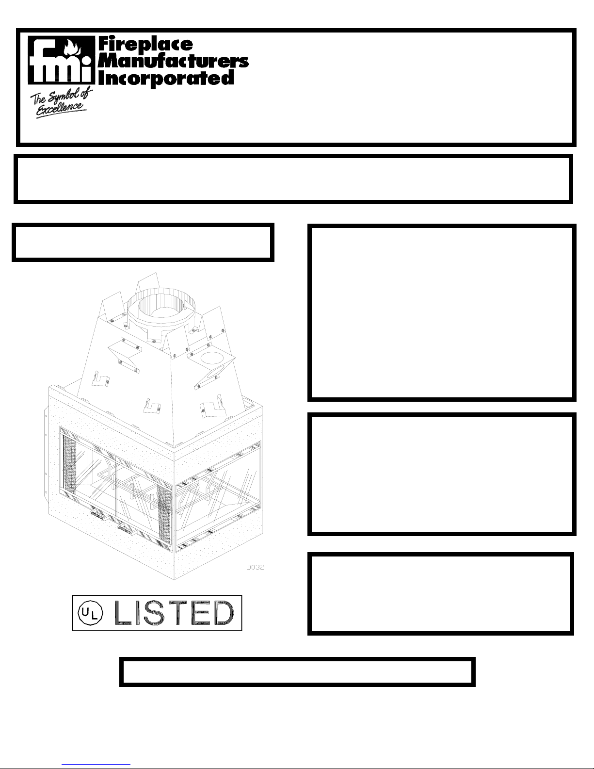
The Monterey
(PENNINSULA)
MODEL PN36
3-SIDED, WOOD-BURNING FIREPLACE
INSTALLATION AND OPERATING INSTRUCTIONS
SAVE THIS BOOK
This book is valuable. In addition to instructing you on how to install and maintain your appliance, it also contains information that will enable
you to obtain replacement parts or optional accessory items when needed. Keep it with your other important papers.
WARNING: ALWAYS LEAVE GLASS DOORS FULLY
OPENED WHEN OPERATING THE APPLIANCE
• Do not store or use gasoline or any other
flammable vapors or liquids in the vicinity
of this or any other appliance.
• Due to high temperatures, the appliance
should be located out of traffic and away
from furniture and draperies.
• Do not place clothing or other flammable
materials on or near the appliance.
• NEVER leave children unattended when a
fire is burning in the fireplace.
FOR YOUR SAFETY
WARNING: IMPROPER INSTALLATION,
ADJUSTMENT, ALTERATION, SERVICE OR
MAINTENANCE CAN CAUSE INJURY,
PROPERTY DAMAGE, OR LOSS OF LIFE.
REFER TO THIS MANUAL. FOR ASSISTANCE
OR ADDITIONAL INFORMATION, CONSULT A
QUALIFIED INSTALLER OR LOCAL
DISTRIBUTOR.
WARNING: THIS FIREPLACE IS INTENDED
FOR USE WITH WOOD, DECORATIVE GAS
APPLIANCE AND VENT FREE GAS LOGS
WHICH BURNS PROPANE OR NATURAL GAS
ONLY.
CHECK LOCAL CODES BEFORE INSTALLING THIS FIREPLACE
MANUFACTURED BY FIREPLACE MANUFACTURERS INC. ICBO ES ER-3507 P/N 55059
2701 S. HARBOR BLVD., SANTA ANA, CA 92704 REV B
Page 2
C O N T E N T S
1. INTRODUCTION.....................................PG. 2
2. SELECTING LOCATION...........................PG. 3
3. CLEARANCES........................................PG. 3
4. FRAMING..............................................PG. 3
5. HEARTH EXTENSIONS...........................PG. 4
6. OUTSIDE AIR KIT INSTALLATION............PG. 5
7. GAS LINE INSTALLATION......................PG. 5
Figure 1
8. CHIMNEY PIPE INSTALLATION.................PG .6
9. FINISHING YOUR CHIMNEY SYSTEM........PG.8
10. TERMINATIONS....................................PG. 10
11.FINISHING YOUR FIREPLACE...................PG. 11
12. OPERATING GUIDELINES AND MAINTENANCE
INSTRUCTIONS...........................................PG. 12
13. REPLACEMENT & ACCESSORY PARTS...PG. 13
NOTE: ALL DIMENSIONS IN THIS INSTALLATION MANUAL ARE IN INCHES UNLESS OTHERWISE SPECIFIED.
1
Page 3
INTRODUCTION
Model PN-36 series us a wood-burning fireplace intended
and approved for installation in either residential homes or
buildings of standard construction.
This model is not for use in mobile homes.
This fireplace system requires the utilization of an FMI 10”
double-wall, snap-lock flue pipe system.
GLASS DOORS are standard with this fireplace and come
in different styles (see parts list on last page).
BE SURE TO CHECK WITH YOUR LOCAL BUILDING CODES FOR AREA REQUIREMENTS BEFORE
INSTALLING THIS FIREPLACE.
The model’s serial number and any other specific rating information may be found on the unit in the UL RATING
PLATE located at the interior of the fireplace’s opening (See
figure 1)
BEFORE YOU BEGIN:
Before beginning the installation of your fireplace; read these
instructions through completely.
This FMI fireplace and its approved components are safe
when installed according to this installation manual and operated as recommended by FMI. Unless your use FMI approved
components tested for this fireplace, YOU MAY CAUSE A
FIRE HAZARD!
The FMI warranty will be voided by, and FMI disclaims any
responsibility for the following actions:
A) Modification of the fireplace or any of the components
manufactured by FMI unless otherwise permitted by FMI.
B) The use of a fireplace insert or any other component part
not approved by FMI in combination with an FMI fireplace.
C) Installation and/or operation in a manner other than instructed in this manual.
D) The burning of any other fuel not tested or approved by
FMI in this wood-burning fireplace.
PROPER INSTALLATION is the most important step in ensuring a safe and continuous operation of this fireplace.
Although grounding may not be required by code in your
area, it must be electrically grounded in accordance with local
codes or, in the absence of local codes, with the National
Electrical Code, ANSI/NFPA 70-1987.
This fireplace is intended for installation in accordance with
the National Fire Protection Association Standard for
Chimneys, Fireplaces, Vents, and Solid-Fuel Burning Fireplaces, NFPA 211, and in accordance with codes such as the
BOCA Basic/National Code, the Standard Mechanical
Code, and the Uniform Building Code.
This wood burning fireplace complies with UL 127 as a
FACTORY BUILT FIREPLACE and is listed and tested
by Underwriters Laboratories Inc.
NOTE: Installation and repair should be done by a qualified
installer. The fireplace and chimney system should be inspected and cleaned before use and periodically thereafter
especially during heating season to ensure a safe operating
system.
THIS FIREPLACE IS NOT INTENDED TO BE USED
AS A PRIMARY SOURCE OF HEAT.
SELECTING LOCATION
To determine the safest and most efficient location for your
fireplace, you must take into consideration the following
guidelines:
1. The location must allow for all the proper clearances (see
section on clearances).
2. Consider a location where the heat output would not be
affected by drafts, air conditioning ducts, windows or doors.
3. A location that avoids the cutting of joists or roof rafters
will make installation easier.
4. If an outside air kit is to be installed, accessibility to outside
combustion air must be considered. This can also be achieved
through a vented crawl space in some cases, for more details
refer to section on outside air kit installation.
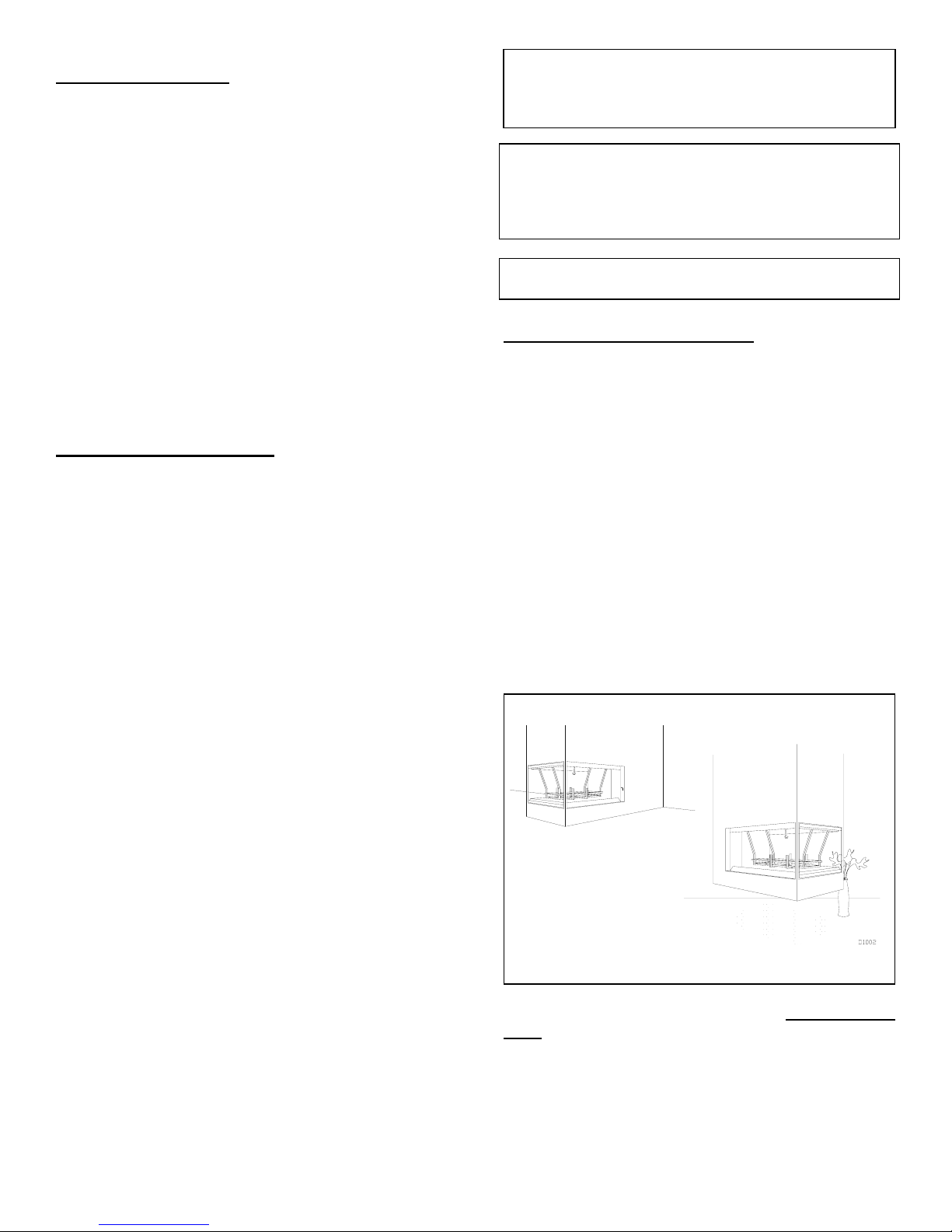
Figure 2
The typical installation for a peninsula is a projected installation, which allows you to extend the fireplace any distance
into the room. A projection may be ideal for a new addition on
an existing, finished wall.
2
Page 4
ALSO IN SELECTING A LOCATION, THE
FOLLOWING PRECAUTIONS MUST BE
OBSERVED:
1. Do not connect this fireplace to a chimney system
other than an FMI chimney system.
2. Install in an area providing ventilation and
adequate combustion air.
3. Due to high temperatures do not locate this
fireplace in high traffic areas or near furniture and
draperies.
4. Provide adequate clearances around air openings
into the combustion chamber. NEVER obstruct the
front opening of the fireplace or the flow of
combustion and ventilation air.
5. Do not locate in or near an area where gasoline or
other flammable liquids may be stored. The fireplace
area must be kept clear and free from these
combustible materials.
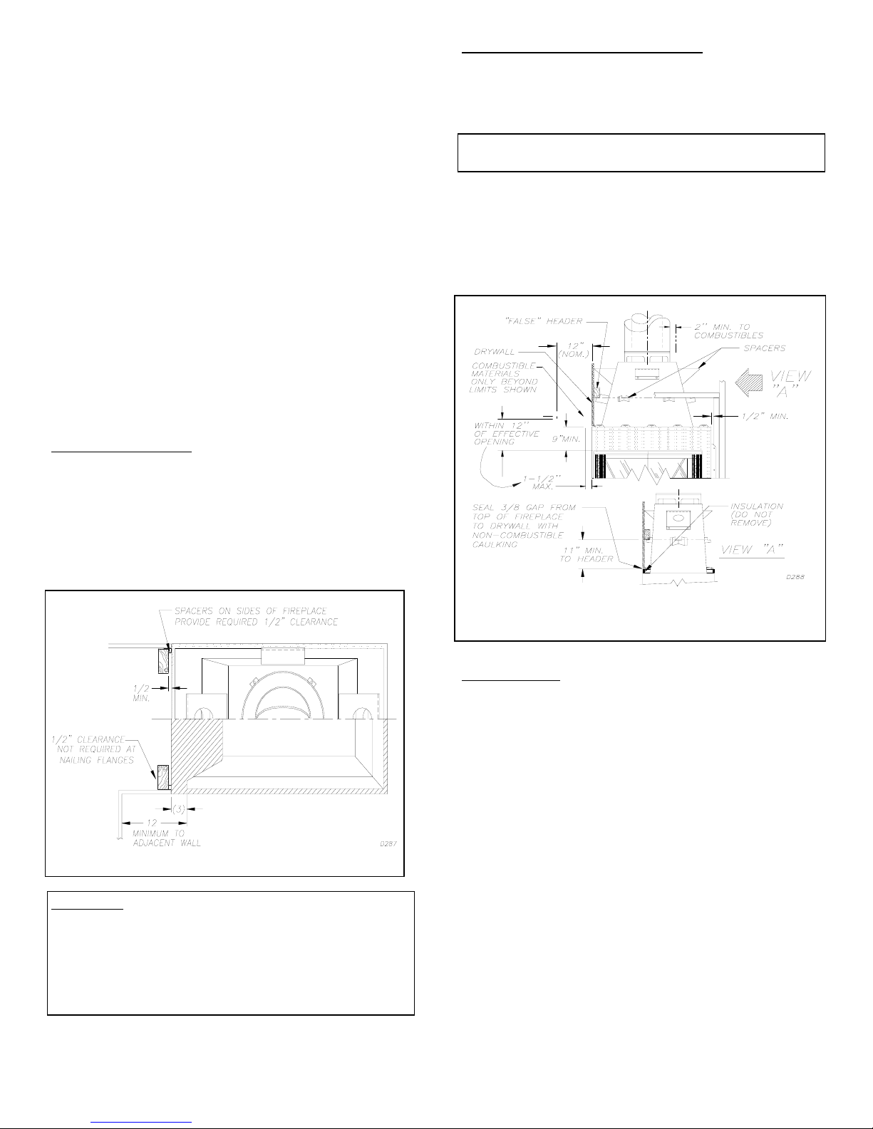
CLEARANCES
MINIMUM CLEARANCES TO
COMBUSTIBLES ARE:
BACK.................................................... ...1/2” MIN.
*
*ADJACENT WALL.......................................12” MIN.
*CHIMNEY OUTER PIPE SURFACES....... ....2” MIN.
*BOTTOM OF FIREPLACE TO FLOOR...... ...0” MIN.
Figure 3
CAUTION: DO NOT BLOCK REQUIRED AIR
SPACES WITH INSULATION OR ANY OTHER
MATERIAL. DO NOT OBSTRUCT EFFECTIVE
OPENING OF FIREPLACE WITH ANY TYPE OF
FACING MATERIAL. COMBUSTIBLE MATERIAL
MUST NOT BE IN CONTACT WITH THE BLACK
FRONT FACE OF THE FIREPLACE.
MANTLE CLEARANCES:
Woodwork, such as wood trims, mantles, and other
combustible materials, should not be placed within 9
inches of the effective opening of this fireplace.
*The effective opening is considered the opening
where actual heat output may occur
Combustible material above and projecting more
than 1-1/2 inches from the fireplaces’ front face (see
fig. 4) should not be placed less than 12 inches from
the effective opening of the fireplace (ref; NFPA std.
7-3.3.3.)
Figure 4
FRAMING
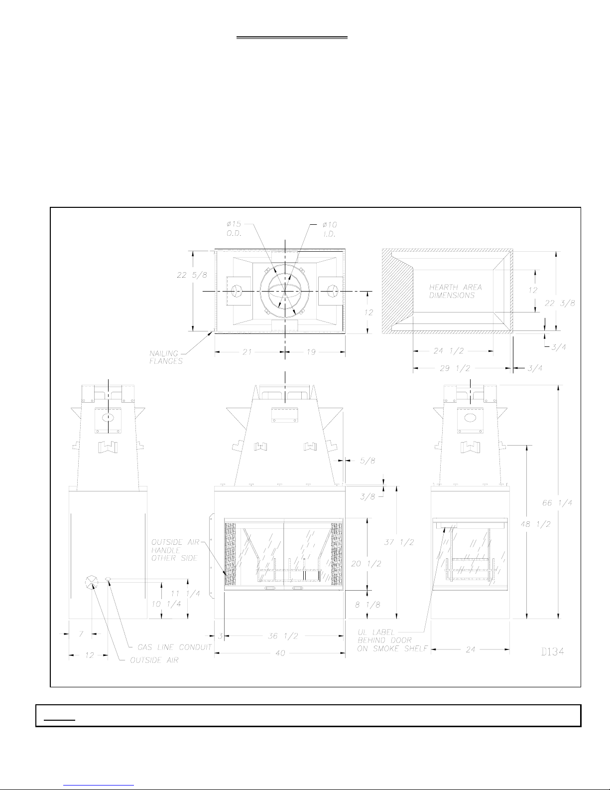
Construct framing using dimensions shown in
figures 5, 7 and 8 depending on your particular
installation.
If the fireplace is to be installed directly on carpeting,
tile (other than ceramic), or any combustible material
other than wood flooring; the fireplace must be
installed upon a metal or wood panel extending the
full width and depth of the fireplace.
Before securing fireplace to prepared framing, metal
safety strips (provided) must be placed between
hearth extensions (not supplied) and bottom front
edge of fireplace to protect against glowing embers
(figure 6).
If the fireplace is to be installed on a raised
platform, a “Z-type” metal safety shield (not
supplied) must be fabricated to fit your required
platform height (see figure 7). The shield must be
made of (26-28ga) galvanized sheet metal to prevent
corrosion.
3
Page 5
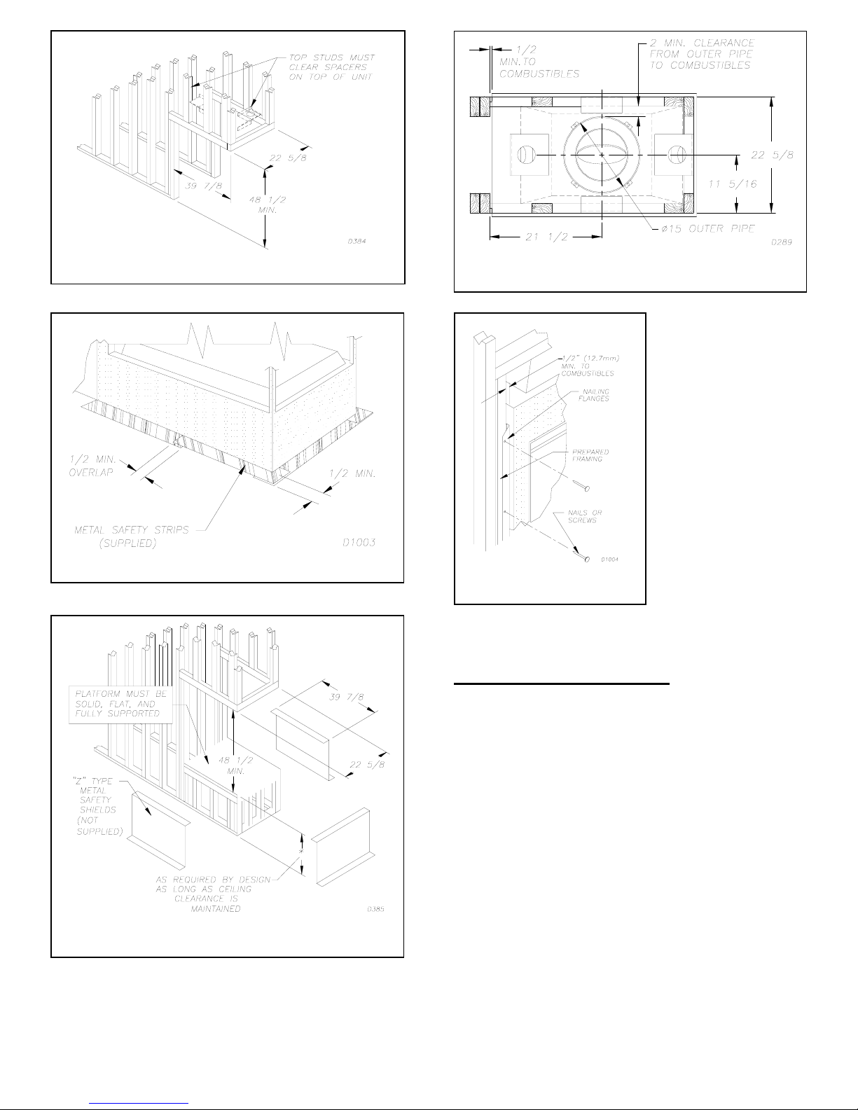
Figure 5
Figure 8
Figure 6
Figure 7
Figure 9
Proceed to secure fireplace to prepared framing
at nailing flanges located
at the sides of the fireplace as shown in figure
9.
HEARTH EXTENSIONS
A hearth extension is required to protect combustible floor
surrounding fireplace. You may obtain kit No. HE-P36 or you
may fabricate your own per the dimensions shown on figure
10.
The hearth extension must project 20 in. min. to the front
and 12 in. min. beyond each side of the fireplace opening except on the end where projection is 16 in. min. to the front and
20 in to the sides. (See figure 10).
4
Page 6

N
GAS SU
Figure 10
Figure 11
If a hearth extension is to be field constructed, it must be
made of non-combustible, inorganic material having an
effective thermal conductivity “K” of .84 BTU In/Ft2 Hr.F
or less at 1” thickness.
Thermal conductivity “K” of materials can be obtained
from the manufacturer.
The minimum required thickness for any material could be
obtained by the following formula:
K factor
.84
If the hearth extension is to be raised, a “Z” type metal
safety strip must be used, see figure 7 and 11.
x 1” = Thickness required
OUTSIDE AIR KIT INSTALLATION
The installation of the outside air kit must be installed during
the rough framing of the fireplace due to the nature of it’s
location. Outside combustion air can be accessed through an
exterior wall or a vented crawl space (see figure 12).
Figure 12
CAUTION: AIR INLET DUCTS MUST NOT
TERMINATE IN ATTIC SPACE.
Avoid installing outside air eyebrow in areas where inlet
opening may be blocked by snow, bushes or other obstacles. It
should also be located beyond the reach of small children.
The maximum height for the air inlet above platform of
fireplace is within 3 feet below the termination flue gas outlet.
For further details on the installation of the outside air kit,
please refer to the instructions included with the kit. For
operating instructions, please refer to your owner’s manual.
GAS LINE INSTALLATION
YOUR GAS SUPPLIER OR A QUALIFIED SERVICE
PERSON SHOULD DO GAS LINE HOOK-UP.
OTE: BEFORE YOU PROCEED, MAKE SURE YOUR
A gas line may be installed for the purpose of installing a
decorative gas appliance available through your local
distributor. Use only ½” black iron pipe and appropriate
fittings. When installing a gas line, a shut-off valve designed
for installation outside the fireplace is recommended.
STEP 1:
refractory (or firebrick) wall located approximately 2” above
the refractory hearth floor. The knockout indentation must be
firmly tapped with any solid object until it is released. Remove
fragmented portion of refractory (see figure 13).
5
PPLY IS OFF!
To install, remove the knockout indentation on the
Page 7

Figure 13
STEP 2:
pull out insulation from gas line conduit sleeve, save insulation for reuse.
STEP 3:
through the rear at 11 1/4” from the floor and through gas line
conduit sleeve. Provide sufficient gas line into fireplace
chamber for fitting connection (see figure 14).
NOTE: Secure incoming line to wood framing to provide
rigidity for threaded end.
STEP 4:
openings. Seal any gaps between gas line and refractory
knock out hole with refractory cement or commercial furnace
cement. Install the decorative gas appliance or cap-off gas
line if desired.
CAUTION:
for leaks after the installation is completed.
After ensuring that the gas valve is on, apply a soap and water solution to all connections and joints. If bubbles appear,
leaks can be detected and corrected.
DO NOT USE AN OPEN FLAME FOR LEAK
TESTING AND DO NOT OPERATE ANY APPLIANCE
IF A LEAK IS DETECTED
Remove gas line cover plate on rear of fireplace and
Run a 1/2” black iron gas line into the fireplace
Figure 14
Repack insulation around gas line and into sleeve
All gas piping and connections must be tested
The gas pipe is intended for connection to a decorative gas
appliance only; (1) incorporating an automatic shut-off device
and (2) complying with the standard for Decorative Gas Appliances for Installation in Vented Fireplaces, ANSI Z21.60 –
1990. ONLY UNVENTED GAS LOG SETS WHICH HAVE
BEEN FOUND TO COMPLY WITH THE STANDARD
FOR UNVENTED ROOM HEATERS, ANZI\IAS\AGA
Z21.11.2, ARE TO BE INSTALLED IN THIS FIREPLACE.
NOTE: An appropriate FMI hood (as shown in page 13)
must be installed when using an unvented gas log set. This
appliance shall also be installed in accordance with the National Fuel Gas code, ANSI Z223.1-1988
CAUTION:
APPLIANCE, THE DAMPER MUST BE REMOVED OR
PERMANENTLY LOCKED IN THE OPEN POSITION.
WHEN USING A DECORATIVE
CHIMNEY PIPE INSTALLATION
The FMI chimney system is a snap-lock, double-wall pipe. It
consists of a stainless steel inner flue pipe, a galvanized outer
pipe, and a wire spacer.
Each section of pipe comes in lengths of 12, 18, 36, and 48
inches but the actual lineal gain for each is measured after
each section is fully connected.
Lineal gain is the actual measurable length of a part after
two or more parts are connected.
LINEAL GAIN
PART NO.
PN36
48-10DM FLUE PIPE 46 3/8
36-10DM FLUE PIPE 34 3/8
18-10DM FLUE PIPE 16 3/8
12-10DM FLUE PIPE 10 3/8
ETL-10D CHASE STYLE
RTL-10D ROUND TOP
DESCRIPTION GAIN (inches)
PENINSULA
FIREPLACE
TEMINATION
TERMINATION
66 ¼
7 TO 17
6
PIPE INSTALLATION
Place pipe assembly (inner and outer with wire spacer) over
starting collar. Inner pipe fits inside inner pipe, outer pipe
fits outside outer pipe.
Begin by aligning hemmed-end of inner flue pipe into the
inner starting flue pipe of fireplace. Push down until hem
“snap-locks” with lances. The outer pipe is just the opposite;
female end has the lances. Continue the same procedure for
the outer pipe (see figure 15).
6
Page 8

Figure 15
Figure 17
It is important to assure that the joint between the chimney
sections is fully locked. Check by pulling chimney upward
after locking.
The chimney should not come apart if properly locked. It
is not necessary to add screws to keep vertical or angled
chimney runs together.
WARNING: THE OPENINGS AROUND THE
STARTING COLLAR ON TOP OF THE FIREPLACE
MUST NEVER BE OBSTRUCTED. NEVER USE
BLOWN INSULATION TO FILL THE CHIMNEY
ENCLOSURE.
FIREPLACE SPACER
Fireplace spacers are required at each point where the chimney penetrates a floor or ceiling, joist space. Their purpose is
twofold; they establish and maintain the required clearance
between the outer pipe and combustible materials, and they
also serve as a shield between floors as required by most
codes.
When penetrating a floor or ceiling at an angle, use firestop
spacer no. 30 FS-10DM, refer to section on accessory items at
the end of this manual.
When the pipe passes through a framed opening into a living
space above, a firestop must be placed on the ceiling below
(figure 16).
When the pipe passes through a framed opening into an attic
space above, a firestop must be placed on the attic floor above
(figure 17).
Figure 16
SUPPORT SECTIONS
The chimney support section is a 4 strap, 12-inch length of
pipe. A chimney support is required every 30 feet above the
fireplace after a straight chimney run, or above a return
elbow after a straight chimney run (fig. 18).
This support is designed to relieve the extra weight load on
the fireplace and elbows when high chimneys are installed.
Figure 18
ELBOW OFFSET INSTALLATION
Chimney weight above offset rests on return elbow. Straps
must be secured with nails to rafters or joists (see figure 19).
Figure 19
7
.
Page 9

g
To achieve desired offset, you may install combinations of
12,18,36, or 48 inch lengths of double wall pipe (see figure
20 and Rise and Offset Chart).
All Joints between
offset should be secured
with two screws, only on
the outer pipe, and shall
not penetrate the inner
stainless.
Figure 20
RISE AND OFFSET CHART
A
4 3/8 16 3/8
9 1/2 25 1/4 1
12 1/2 30 3/8 1
14 3/8 34 2
17 5/8 39 1/4 1 1
21 1/2 46 1
22 3/4 48 1/8 1 2
26 3/8 54 7/8 1
26 3/8 60 1 1
31 3/4 63 3/4 1 1
34 3/4 69 1 1
38 5/8 75 5/8 2
39 7/8 77 7/8 1 1 1
43 3/4 84 1/2 1 1
46 3/4 87 3/4 2 1
48 7/8 93 3/8 2
Maximum length of pipe between supports is 6 feet of angled
run. A maximum of two 6 foot angled run sections per
chimney system (see figure 21).
B 48 36 18 12
Figure 21
Figure 22
FINISHING YOUR CHIMNEY SYSTEM
10 FOOT RULE
All chimney termination must extend a minimum of 3
feet above the hi
roof and must be at least 2 feet above the roof within a
10 foot horizontal span (see figure 22).
hest point where it passes through the
IMPORTANT: If an exposed portion of chimney is
greater than 4 feet above the roof line, use support wires to
keep chimney secure. The support wires may be attached to
the outer pipe of the chimney with screws, provided the
screws do not penetrate the inner flue pipe.
WARNING: DO NOT OPERATE AN UNVENTED GAS
LOG SET IN THIS FIREPLACE WITH THE CHIMNEY
REMOVED.
8
Page 10

Figure 23
MINIMUM CHIMNEY HEIGHT
The minimum chimney height (measured from bottom of
fireplace to flue gas outlet-end of pipe) is 15 feet for a straight
run, 16 feet min. For a run with 1 elbow sets (a set consists of
one starter elbow and one return elbow).
Uncommon circumstances such as neighboring hills, tall
trees, or strong wind areas can cause downdrafts in the chimney system. In such cases going beyond the minimum recommended height would be preferable to provide a better draw.
MAXIMUM CHIMNEY HEIGHT
The maximum height approved for any chimney run with
this fireplace system is 50 feet measured from bottom of fireplace to flue outlet-end of pipe.
CHIMNEY MAINTENANCE
Have your chimney system cleaned and inspected regularly
to ensure safe and efficient operation. Refer to your Owners
Manual for further guidelines on maintenance and operation.
Using figure 24 and the chart below, determine the opening
that will be required for the pitch of your particular roof.
Figure 24
ROOF OPENING CHART
PITCH
FLAT 19 6F10
6/12
(26.6 DEG. SLOPE)
12/12
(45 DEG. SLOPE)
18/12
(56.3 DEG. SLOPE)
24/12
(63.4 DEG. SLOPE)
Before cutting hole, temporarily remove shingles around area
to be opened. After preparing the opening on the roof, continue to add sections of pipe until it extends a minimum of 30
inches above highest point of roof cut-out (see figure 24).
With the termination the minimum height should add up 3
feet (see 10-foot rule and figure 22).
OPENING
“A”
23 ¼ 6F10
30 ¾ 12F10
40 1/8 18F10
50 ¼ 24F10
USE FLASHING
NO.
9
Page 11

FLASHING INSTALLATION
Determine the flashing to be used with the roof-opening
chart. Slide flashing over pipe until base is flat against roof.
Replace as many shingles as needed to cover exposed area and
flashing base. Secure in position by nailing through shingles.
DO NOT NAIL THROUGH FLASHING CONE.
Figure 25
STORM COLLAR INSTALLATION
Place storm collar over pipe and slide down until snug
against the open edge of the flashing (see figure 26).
Figure 26
Apply waterproof caulking to all seams and notched around
storm collar and also at base around shingles.
TERMINATIONS
The fireplace system must be terminated with the listed
round top or chase terminations. Refer to the installation instructions supplied with the termination.
The terminations approved for this fireplace are RTL-10D,
which can be used for flashing or chase and ETL-10D for
chase style termination only. Figure 27 shows an RTL-10D
round top termination.
Figure 27
CAUTION: DO NOT SEAL OPENINGS ON THE ROOF-
TOP FLASHING. FOLLOW THE INSTALLATION INSTRUCTIONS PROVIDED WITH THE TERMINATION
BEING USED.
CHASE INSTALLATIONS
Instructions for chase installations are included with the
chase style termination chosen although it is worthy to mention here that in a multiple chase installation, provide adequate
distance between termination’s or smoke spillage from one
termination to another may occur. We suggest they be separated at least 30” center to center and stacked at a vertical
height difference of 18” vertically from one termination to the
other (see figure 28).
Figure 28
10
Page 12

FINISHING YOUR FIREPLACE
CABINET DOOR INSTALLATION
Glass doors have been provided with this fireplace. A set
includes the front glass panel assembly. They come in different styles, check with your local distributor for availability
and options.
To install doors and front panel, simply insert top door pin(s)
up into hole(s) on top frame, and insert bottom pin (D) into
hole(S) on bottom frame until door is fully seated.
No alignments or adjustments are necessary (see fig. 29).
When placing facing at the upper edge of the effective opening of the fireplace, provide an “L” shaped piece of metal extending the full width of the opening.
Secure with sheet metal screws at a distance high enough
from the edge as to not interfere with the operation of doors.
This assures that the facing material, in time, should not block
the opening if it where to lose cohesion.
FLASHING MANTLES:
Mantles, combustible or non-combustible, may be constructed
(see below) as long as the proper clearances are observed.
Refer to page 2 for clearances.
Figure 29
FIREPLACE FACING
Any non-combustible material may be used for facing (glass,
title, brick, etc.) as long as the proper clearances are adhered
to (refer to section on clearances) and the fireplace opening
are not blocked or obstructed in any way (see fig. 30).
Use only heat resistant, non-combustible mortar or adhesive
when securing facing material to the front of the fireplace.
Figure 30
Figure 30 D1018
11
Page 13

OPERATING GUIDELINES AND
MAINTENANCE INSTRUCTIONS
GLASS DOORS
Only the cabinet type doors can be opened, the front glass
panel assembly is stationary and must be installed with doors.
When fireplace is in operation, both sets of cabinet doors on
each side of fireplace, must be in the
FULLY OPEN or
FULLY CLOSED position only or a fire hazard may be
created (see figure 32).
Figure 32
DAMPER MECHANISM
The damper control lever is located inside the fire chamber
(see figure 33). Make sure lever is cool before handling. Pull
down to CLOSE,
open when lighting a fire; not doing so will cause smoke spillage into the room.
When the fireplace is not in use, close the damper to prevent
downdrafts to enter room.
The damper mechanism should be per the following figure.
push up to OPEN. The damper must be
OUTSIDE AIR MECHANISM
The outside air handle is located at the right hand side of the
fireplace rear refractor (fig. 33). Pull to close, push to open,
Always open the mechanism when starting a fire, this provides adequate outside combustion air. Close the mechanism
when not in use to prevent cold air from entering the room.
Periodically check your outside air intake vent hood for any
possible obstructions (snow, bushes, etc.).
Figure 33
GRATE
The grate is designed to provide you with the maximum solid
fuel capacity, do not attempt to defeat its purpose, doing so
may cause smoke spillage and may cause a fire hazard.
Do not overload the grate or obstruct the required air space
beneath it. Always keep ashes from building up under the
grate.
WARNING:
FMI MODEL 36PN GR GRATE ONLY.
Never obstruct the flow of combustion and ventilation air.
Keep the front of the fireplace clear of all obstacles and
materials.
RISK OF FIRE! REPLACE GRATE WITH
WARNING:
CHILDREN AND ADULTS SHOULD BE ALERTED
TO THE HAZARDS OF HIGH SURFACE TEMPERATURES AND TO STAY AWAY FROM THESE TO
AVOID BURNS OR CLOTHING IGNITION.
YOUNG CHILDREN SHOULD BE CAREFULLY SUPERVISED WHEN THEY ARE IN THE SAME ROOM
AS THE FIREPLACE.
FOR FURTHER OPERATING GUIDELINES, INSTRUCTIONS AND WARRANTY INFORMATION PLEASE REFER TO YOUR OWNERS’ MANUAL OR CONTACT
YOUR AUTHORIZED DEALER.
12
Page 14

REPLACEMENT AND ACCESSORY PARTS
* When ordering replacement or accessory items, please have your fireplace’s model name or number and the part number of the
item(s) you are ordering ready.
* The model name or number of your fireplace may be found on the rating plate located inside the fireplace (see figure 1).
*Refer to the parts list and diagrams when ordering replacement parts for your fireplace.
* Repair parts or accessory items may be bought from your distributor/dealer or directly from FMI.
*All product specifications are subject to change without notice.
NOTE: USE OF ANY OTHER GLASS DOOR ASSEMBLY NOT TESTED WITH THIS FIREPLACE MAY CONSTITUTE A
FIRE HAZARD AND WILL VOID THE FMI WARRANTY.
13
 Loading...