

Page 1
DIRECT VENT FIREPLACE
PFS
®
USC
OWNER’S OPERATION AND INSTALLATION MANUAL
MODELS CD36M-LS WITH FAN AND DOOR SWITCH
AND CD42M-LS WITH FAN
WARNING: If the information in this manual is not
followed exactly, a re or explosion may result causing
property damage, personal injury or loss of life.
— Do not store or use gasoline or other ammable
vapors and liquids in the vicinity of this or any other
appliance.
— WHAT TO DO IF YOU SMELL GAS
• Do not try to light any appliance.
• Do not touch any electrical switch; do not use any
phone in your building.
• Immediately call your gas supplier from a neighbor’s
phone. Follow the gas supplier’s instructions.
• If you cannot reach your gas supplier, call the re
department.
— Installation and service must be performed by a quali-
ed installer, service agency or the gas supplier.
INSTALLER: Leave this manual with the appliance.
CONSUMER: Retain this manual for future reference.
For more information, visit www.fmiproducts.com
Page 2
TABLE OF CONTENTS
Introduction .......................................................... 3
Selecting Location ............................................... 3
Local Codes......................................................... 4
Safety .................................................................. 4
Product Features ................................................. 6
Pre-Installation Preparation .................................. 6
Requirements for the Commonwealth of
Massachusetts..................................................... 9
Installation ......................................................... 10
Burner Flame Adjustment .................................. 23
SAVE THIS BOOK
This book is valuable. In addition to instructing you on how to install and
maintain your appliance, it also contains information that will enable you to
obtain replacement parts or optional accessory items when needed. Keep
it with your other important papers.
WARNING: Improper installation, adjustment, al-
Operation ........................................................... 24
Gas Conversion ................................................. 26
Cleaning and Maintenance ................................ 27
Troubleshooting ................................................. 29
Specications .................................................... 33
Replacement Parts ............................................ 33
Service Hints ..................................................... 33
Technical Service............................................... 33
Parts .................................................................. 34
Accessories ....................................................... 38
Limited Two Year Warranty ..................Back Cover
teration, service or maintenance can cause injury or
property damage. Refer to this manual for correct installation and operational procedures. For assistance
or additional information consult a qualied installer,
service agency or the gas supplier.
WARNING: This direct vent gas replace is intended
for use with natural or propane/LP gas only. Do not attempt to burn any solid fuels in this appliance.
This replace may be installed as an OEM installation
in a manufactured (mobile) home and must be installed
in accordance with the manufacturers instructions and
the Manufactured Home Construction and Safety Stan-
dard, Title 24 CFR, Part 3280 in the United States or the
Mobile Home Standard, CAN/CSA Z240 MH Series, in
Canada. This replace is only for use with the type(s)
of gas indicated on the rating plate. A conversion kit is
supplied with the replace.
State of Massachusetts: The installation must be made
by a licensed plumber or gas tter in the Commonwealth
of Massachusetts.
www.fmiproducts.com
125205-01E2
Page 3
INTRODUCTION
This FMI PRODUCTS, LLC replace and its
WARNING: This product contains and/or generates chemicals
known to the State of California
to cause cancer or birth defects
or other reproductive harm.
Model CD36M-LS and CD42M-LS is a heat
circulating gravity direct vent replace with
sealed combustion chamber. This replace
uses millivolt gas control valve and millivolt
ignition system.
This replace is convertible with the standard
setup as natural gas. Conversion may be performed by the OEM mobile home builder or by
a qualied service person on-site. If you are
uncertain as to what gas your unit is equipped
for, please check the rating plate located inside of the appliance opening or consult your
mobile home supplier or your local distributor
of FMI PRODUCTS, LLC.
NOTICE: Check local building
codes for area requirements before installing this appliance.
BEFORE YOU BEGIN
Before beginning the installation of your
appliance, read these instructions through
completely.
components are safe when installed according to this installation manual and operated as
recommended. Unless you use FMI PRODUCTS, LLC components designed and tested
for this replace system, YOU MAY CAUSE
A SAFETY HAZARD!
The FMI PRODUCTS, LLC warranty will
be voided by, and FMI PRODUCTS, LLC
disclaims any responsibility for the following
actions:
A) Modication to the replace, components,
doors, blower, fans or vent system.
B) Use of any component part not manufac-
tured or approved by FMI PRODUCTS,
LLC in combination with a FMI PROD-
UCTS, LLC replace system.
Proper installation is the most important step
in ensuring safe and continuous operation
of the replace. Consult the local building
codes as to the particular requirements
concerned with the installation of all factory
built replaces. This replace, when installed,
must be electrically grounded in accordance
with local codes or in the absence of local
codes, with the National Electrical Code,
ANSI/NFPA 70.
The installation must conform with local codes
or, in the absence of local codes, with the
National Fuel Gas Code, ANSI Z223.1. This
appliance complies with ANSI Z21.88.
SELECTING LOCATION
To determine the safest and most efcient
location for your replace, consider the fol-
lowing guidelines:
1. The location must allow for proper clearances (see Figure 1).
• Flush installation is recommended where
living space is limited.
• Projected installation may be ideal for
a new addition to an existing nished
wall.
• Corner installation makes use of a space
that may not normally be used and pro-
vides a wider and more efcient range
for radiant heat transfer.
2. Consider a location where the replace
would not be affected by drafts, air conditioning ducts, windows or doors.
3. A location that avoids the cutting of joists
or roof rafters makes ventilation installation easier.
125205-01E 3
www.fmiproducts.com
In selecting a location, the following precautions must be observed:
• Do not connect this appliance to a chimney
system used for solid fuel burning replace.
• Due to high temperatures, do not locate
this appliance in high trafc areas or near
furniture and draperies.
FULL
PROJECTION
Figure 1 - Common Fireplace Locations
CORNER
INSTALLATION
FLUSH
INSTALLATION
Page 4
SELECTING LOCATION
Continued
• Never obstruct openings of the appliance or
ow of ventilation air. Keep control compart-
ments accessible.
• Do not locate appliance close to where
gasoline or other ammable liquids may be
stored. The appliance must be kept clear
and free from combustible materials.
• Do not use this appliance if any part has
been under water. Immediately contact a
local service technician to examine the
appliance and to replace any part(s) of the
control ignition system and other related
components that have been submerged
under water.
SAFETY
DANGER: Carbon monoxide
poisoning may lead to death!
This replace must be installed by the O.E.M.
builder or by a qualied (certied or licensed)
service person. It has a sealed gas combustion
chamber that uses a coaxial pipe (pipe within
a pipe and having the same center) venting
system. It brings in fresh air for combustion
through the outer pipe and combustion gases
are exhausted through the inner pipe. If the
glass door assembly and venting pipe are not
properly seated, connected and sealed, carbon
monoxide leakage (spillage) can occur.
This fireplace complies with the National
Safety Standards and is listed and tested by
PFS Corporation to ANSI Z21.50/CSA 2.22
standard as vented gas replace.
NOTICE: Decorative product not
for use as a heating appliance.
Carbon Monoxide Poisoning: Early signs
of carbon monoxide poisoning resemble the
u, with headaches, dizziness or nausea. If
you have these signs, the replace may not
be working properly. Get fresh air at once!
Have replace serviced. Some people are
more affected by carbon monoxide than others. These include pregnant women, people
with heart or lung disease or anemia, those
under the inuence of alcohol and those at
high altitudes.
Propane/LP & Natural Gas: Propane/LP and
natural gas are odorless. An odor-making
agent is added to the gas. The odor helps you
detect a gas leak. However, the odor added to
the gas can fade. Gas may be present even
www.fmiproducts.com
LOCAL CODES
Install and use replace with care. Follow all
local codes. In the absence to local codes,
use the current National Fuel Gas Code ANSI
Z223.1/NFPA 54* (USA) or the current CSAB149.1 Installation Code (Canada).
*Available from:
American National Standards Institute, Inc.
1430 Broadway
New York, NY 10018
National Fire Protection Association, Inc.
Batterymarch Park
Quincy, MA 02269
though no odor exists.
Make certain you read and understand all
warnings. Keep this manual for reference. It
is your guide to safe and proper operation of
this replace.
WARNING: Any change to
this replace or it’s controls can
be dangerous. Do not modify
this replace under any circumstances. Any parts removed for
servicing must be replaced prior
to operating replace.
WARNING: Do not use a
blower insert, heat exchanger
insert or other accessory not approved for use with this replace.
WARNING: This appliance
is only for use with the type of
gas indicated on the rating plate.
This appliance is not convertible
for use with other gases unless
a certied kit is used.
WARNING: Do not allow fans
to blow directly into the replace.
Avoid any drafts that alter burner
ame patterns.
125205-01E4
Page 5
SAFETY
Continued
Due to high temperatures, the appliance should be located out of
trafc and away from furniture and draperies.
Do not place clothing or other ammable material on or near the
appliance. Never place any objects on the appliance.
Do not use this replace to cook food or burn paper or other ammable material.
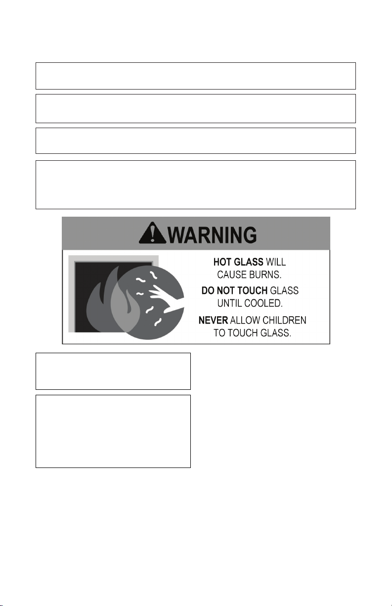
This replace reaches high temperatures. Keep children and adults
away from hot surface to avoid burns or clothing ignition. Fireplace
will remain hot for a time after shutdown. Allow surface to cool
before touching.
Carefully supervise young chil-
dren when they are in the room
with replace.
Keep the area around your
replace clear of combustible
materials, gasoline and other
ammable vapor or liquids. Do
not run replace where these
are used or stored.
1. For propane/LP replace, do not place
propane/LP supply tank(s) inside any
structure. Locate propane/LP supply
tank(s) outdoors. To prevent performance
problems, do not use propane/LP fuel tank
of less than 100 lbs. capacity.
2. If you smell gas
• shut off gas supply
• do not try to light any appliance
• do not touch any electrical switch; do not
125205-01E 5
www.fmiproducts.com
use any phone in your building
• immediately call your gas supplier from
a neighbor’s phone. Follow the gas supplier's instructions
• if you cannot reach you gas supplier, call
the re department.
3. Never install the replace
• in windy or drafty areas where curtains
or other combustible (ammable) objects
can make contact with the replace front
• in high trafc areas
4. Turn fireplace off and let cool before
servicing, installing or repairing. Only a
qualied service person should install,
service or repair this replace. Have replace inspected annually by a qualied
service person.
5. You must keep control compartments,
burners and circulating air passages clean.
More frequent cleaning may be needed due
to excessive lint and dust from carpeting,
bedding material, etc. Turn off the gas valve
and pilot light before cleaning replace.
Page 6

SAFETY
Continued
6. Have venting system inspected annually
by a qualied service person. If needed,
have venting system cleaned or repaired.
7. Do not use any solid fuels (wood, coal,
paper, cardboard, etc.) in this replace.
Use only the gas type indicated on re-
place nameplate.
8. This appliance, when installed, must be
electrically grounded in accordance with
local codes or, in the absence of local
codes, with the National Electrical Code,
ANSI/NFPA 70.
PRODUCT FEATURES
These are a few facts that can help you un-
derstand and enjoy your direct-vent replace:
• The venting system may be routed to the
outside of your home in several ways. It
may vent through the roof (vertical) or it
may vent to an outside/exterior wall (hori-
zontal). The vent pipe installation is very
important to allow for proper operation.
You must follow the venting instructions
very carefully for either vertical or horizontal
applications.
• This replace may be installed in any room
of your house provided all local codes and
these installation instructions are followed.
• A piezo ignitor and ceramic electrode cre-
ate spark to ignite the pilot light. It does not
require any matches, batteries or any other
sources of ignition to light the pilot.
• Each time you turn on your replace, you
PRE-INSTALLATION PREPARATION
9. Do not use replace if any part has been
exposed to or under water. Immediately
call a qualied service person to arrange
for replacement of the unit.
10. Do not operate replace if any log is
broken.
11. Do not operate replace with glass door
removed, cracked or broken.
12. Provide adequate clearances around air
openings.
may notice some amount of condensation
on the inside of the replace glass. This
is normal and will disappear after 10-20
minutes of operation.
• Your direct-vent gas fireplace system
(replace and venting) is a balanced and
sealed gas operating unit. It requires approximately 10-20 minutes of operating
time before the ame pattern stabilizes.
• This replace is equipped with a millivolt
gas control system that does not require
electricity to operate. A piezo ignitor is
provided to light the pilot without using
matches or lighters.
• This model can accept an optional circulat-
ing air blower when 120 VAC connection is
supplied. If you plan to install an optional
blower, do not forget to wire the replace
outlet when framing.
CAUTION: Do not block
required air spaces with insulation or any other material. Do not
obstruct the effective opening
of the appliance with any type
of facing material.
CLEARANCES TO COMBUSTIBLES
Minimum clearances to combustibles for the
replace are:
• Back and Sides of Fireplace ........ 0"
• Floor ..........................0"
• Perpendicular Wall ...............6"
• Front ......................... 36"
• Top of Standoffs .................. 0"
www.fmiproducts.com
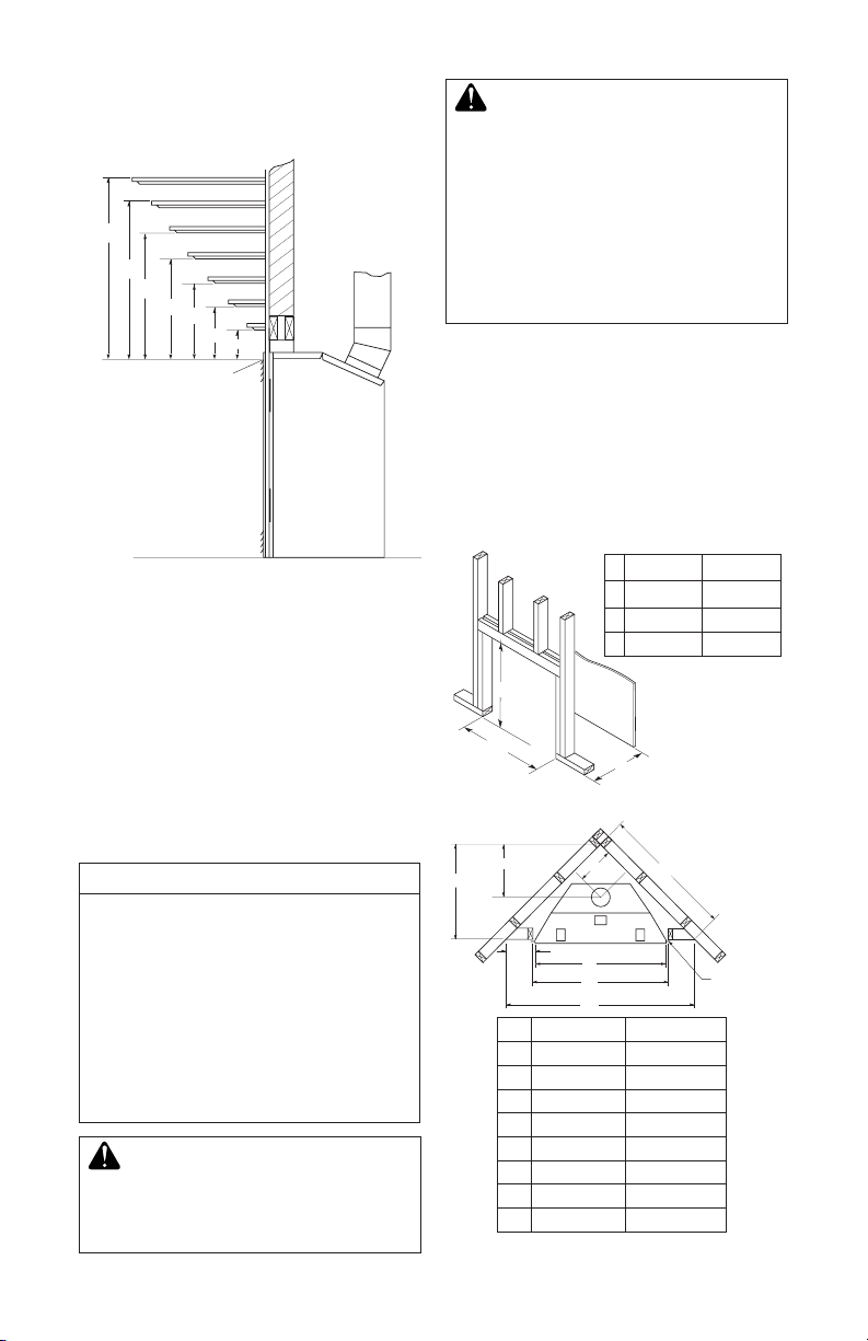
MANTEL CLEARANCES
Woodwork, such as wood trims, mantles
and other combustible materials should be
placed within the required clearance speci-
ed in Figure 2.
Mantel Depth Mantel From Top of Opening
(1) 14" (A) 16"
(2) 12" (B) 14"
(3) 10" (C) 12"
(4) 8" (D) 10"
(5) 6" (E) 8"
(6) 4" (F) 6"
(7) 2" (G) 4"
125205-01E6
Page 7
PRE-INSTALLATION
A
B
E
F
G
H
D
C
Nailing Tabs
C
B
A
D
E
F
G
Top of Louver Opening
3
2
1
4
5
6
7
Wall
B
A
C
PREPARATION
Continued
WARNING: Horizontal sec-
tions of this vent system require
a minimum clearance of 2" from
the top of the pipe and 1" minimum to the sides and bottom.
Vertical sections of this system
require a minimum of 1" clearance to combustible materials
on all sides of the pipe.
FRAMING
Once the nal location has been determined, observing height clearances for vent termination, you
may construct framing using dimensions shown in
Figures 3 and 4, depending on your installation.
If the appliance is to be installed directly on
carpeting, tile (other than ceramic) or any combustible material other than wood ooring, appliance must be installed on a metal or wood panel
extending full width and depth of the appliance.
Figure 2 - Mantel Clearances
VENT TERMINATION CLEARANCES
Final position of your replace depends on
location of the vent termination in relation to
CD36M-LS CD42M-LS
A 36 1/8" 40 1/8"
B 41 1/4" 48 1/4"
C 23 1/2" 25 5/8"
clearances that must be observed as shown
in Figure 5 on page 8.
The vent system serves as the “chimney” as
well as combustion air supply (air intake).
The horizontal run must have a rise of 1/4"
(0.6 cm) for every 12" (30.48 cm) of horizon-
tal run towards the termination. Maximum
horizontal run depends on vertical rise from
Figure 3 - Framing Dimension
replace adapter collar to vent termination
(see table below).
VERTICAL HORIZONTAL
0 to 1 ft (30.48 cm)
1 ft (30.48 cm) to 4 ft (121.92 cm)
2 ft (60.96 cm) to 8 ft (243.84 cm)
3 ft (91.44 cm) to 12 ft (365.76 cm)
4 ft (121.92 cm) to 16 ft (487.68 cm)
5 ft (152.40 cm) to 15 ft (457.20 cm)
6 ft (182.88 cm) to 14 ft (426.72 cm)
7 ft (213.36 cm) to 13 ft (396.24 cm)
8 ft (243.84 cm) to 12 ft (365.76 cm)
vent to run downward as this
may cause excessive temperatures which could cause a re.
125205-01E 7
WARNING: Never allow the
www.fmiproducts.com
CD36M-LS CD42M-LS
A 35 3/4" 41 5/8"
B 15" 21 5/8"
C 49 5/8" 58 1/2"
D 10 3/8" 13 1/2"
E 13 3/4" 16 3/4"
F 41" 48"
G 41 1/4" 48 1/4"
H 68 1/2" 81 1/2"
Figure 4 - Corner Installation
Page 8
Fixed
Closed
Openable
Fixed
Closed
V
V
V
V
V
V
V
V
X
X
V
X
G
G
J
F
B
B
K
N
H
I
A
N
E
L
D
B
M
A
C
B
V
V
A
G
G
B
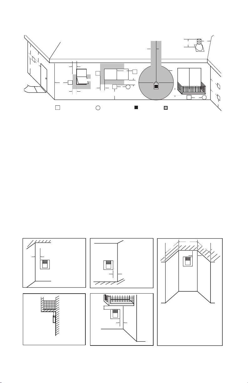
TERMINATION CAP
AIR SUPPLY INLET
GAS METERRESTRICTED AREA
(TERMINATION PROHIBITED)
A = clearance above grade, veranda, porch, deck, or
balcony [*12" (30.5 cm) minimum]
B = clearance to window or door that may be opened
[6" (15 cm) min. for 10,000 Btu or less; 9" (23 cm) in US
if between 10,000 and 50,000, 12" (30 cm) in Canada
if between 10,000 and 100,000; 12" (30 cm) in US if
greater than 50,000, 36" (91 cm) in Canada if greater
than 100,000]
C = clearance to permanently closed window
[minimum 12" (30.5 cm) recommended to prevent
condensation on window]
D = vertical clearance to ventilated soffit located above the
terminal within a horizontal distance of 24" (61 cm) from
the center-line of the terminal [18" (45.7 cm) minimum]
E = clearance to unventilated soffit [12" (30.5 cm) minimum]
F = clearance to outside corner (see below)
G = clearance to inside corner (see below)
H = *not to be installed above a meter/regulator assembly
within 36" (91.4 cm) horizontally from the center line
of the regulator
I = clearance to service regulator vent outlet [*72" (182.9 cm)
minimum]
J = clearance to non-mechanical air supply inlet to building
or the combustion air inlet to any other fireplace
[6" (15 cm) min. for 10,000 Btu or less; 9" (23 cm) in US
if between 10,000 and 50,000, 12" (30 cm) in Canada
if between 10,000 and 100,000; 12" (30 cm) in US if
greater than 50,000, 36" (91 cm) in Canada if greater
than 100,000]
K = clearance to a mechanical air supply inlet [*In Canada,
6 ft. (1.83m) minimum; In US 3 ft. (91 cm) above if within
10 ft. (3 m) horizontally]
L = † clearance above paved side-walk or a paved driveway
located on public property [*84" (213.3 cm) minimum]
M = clearance under veranda, porch, deck
[*12" (30.5 cm) minimum ‡]
N = clearance above a roof shall extend a minimum of
24" (61 cm) above the highest point when it passes
through the roof surface and any other obstruction within
a horizontal distance of 18" (45.7 cm)
† vent shall not terminate directly above a side-walk or paved driveway which is located between two
single family dwellings and serves both dwellings*
‡ only permitted if veranda, porch, deck or balconey is fully open on a minimum of 2 sides beneath the floor*
* as specified in CAN/CSA B149 (.1 or .2) Installation Codes (1991) for Canada and U.S.A.
Note: Local codes or regulations may require different clearances
A = 6" (15.2 cm)
Inside Corner
V
B
E
V
B = 6" (15.2 cm)
C = Maximum depth of 48" (121.9 cm)
for recessed location
D = Minimum width for back wall of
recessed location Combustible - 38" (965 mm)
Noncombustible - 24" (61 cm)
E = Clearance from corner in
recessed location Combustible - 6" (15.2 cm)
Noncombustible - 2" (5.1 cm)
Outside Corner Recessed Location
G
H
G = 12" (30.5 cm) minimum clearance
Balcony with No Side Wall
V
J
Combustible &
Noncombustible
H = 24" (61 cm)
J = 20" (50.8 cm)
Balcony with Perpendicular Side Wall
C
D
C
Termination Clearances for Buildings with Combustible and Noncombustible Exteriors
Openable
PRE-INSTALLATION PREPARATION
Continued
Figure 5 - Minimum Clearances for Vent Terminations
www.fmiproducts.com
125205-01E8
Page 9

REQUIREMENTS FOR THE COMMONWEALTH OF
MASSACHUSETTS
For all side wall horizontally vented gas fueled
equipment installed in every dwelling, building or
structure used in whole or in part for residential
purposes, including those owned or operated by
the Commonwealth and where the side wall exhaust vent termination is less than seven (7) feet
above nished grade in the area of the venting,
including but not limited to decks and porches,
the following requirements shall be satised:
INSTALLATION OF CARBON
MONOXIDE DETECTORS
At the time of installation of the side wall horizontal vented gas fueled equipment, the installing
plumber or gas tter shall observe that a hard
wired carbon monoxide detector with an alarm
and battery backup is installed on the oor level
where the gas equipment is to be installed. In
addition, the installing plumber or gas tter shall
observe that a battery operated or hard wired carbon monoxide detector with an alarm is installed
on each additional level of the dwelling, building or
structure served by the side wall horizontal vented
gas fueled equipment. It shall be the responsibility
of the property owner to secure the services of
qualied licensed professionals for the installation
of hard wired carbon monoxide detectors.
In the event that the side wall horizontally
vented gas fueled equipment is installed
in a crawl space or an attic, the hard wired
carbon monoxide detector with alarm and
battery back-up may be installed on the next
adjacent oor level.
In the event that the requirements of this
subdivision can not be met at the time of
completion of installation, the owner shall
have a period of thirty (30) days to comply with
the above requirements; provided, however,
that during said thirty (30) day period, a battery
operated carbon monoxide detector with an
alarm shall be installed.
Approved Carbon Monoxide Detectors
Each carbon monoxide detector as required
in accordance with the above provisions shall
comply with NFPA 720 and be ANSI/UL 2034
listed and IAS certied.
SIGNAGE
A metal or plastic identication plate shall be
permanently mounted to the exterior of the
building at a minimum height of eight (8) feet
above grade directly in line with the exhaust
vent terminal for the horizontally vented gas
fueled heating appliance or equipment. The
sign shall read, in print size no less than 1/2" in
size, "GAS VENT DIRECTLY BELOW. KEEP
CLEAR OF ALL OBSTRUCTIONS".
125205-01E 9
www.fmiproducts.com
INSPECTION
The state or local gas inspector of the side
wall horizontally vented gas fueled equipment
shall not approve the installation unless, upon
inspection, the inspector observes carbon
monoxide detectors and signage installed in
accordance with the provisions of 248 CMR
5.08(2)(a) 1 through 4.
EXEMPTIONS: The following equipment is
exempt from 248 CMR 5.08(2)(a) 1 through 4:
• The equipment listed in Chapter 10 entitled
"Equipment Not Required To Be Vented"
in the most current edition of NFPA 54 as
adopted by the Board; and
• Product Approved side wall horizontally
vented gas fueled equipment installed in a
room or structure separate from the dwelling, building or structure used in whole or
in part for residential purposes.
MANUFACTURER REQUIREMENTS
Gas Equipment Venting System Provided
When the manufacturer of Product Approved
side wall horizontally vented gas equipment
provides a venting system design or venting
system components with the equipment, the
instructions provided by the manufacturer for
installation of the equipment and the venting
system shall include:
• Detailed instructions for the installation of
the venting system design or the venting
system components; and
• A complete parts list for the venting system
design or venting system.
Gas Equipment Venting System Not
Provided
When the manufacturer of a Product Approved side wall horizontally vented gas fueled equipment does not provide the parts for
venting the ue gases, but identies "special
venting systems", the following requirements
shall be satised by the manufacturer:
•
The referenced "special venting system" instructions shall be included with the appliance
or equipment installation instructions; and
• The "special venting systems" shall be Prod-
uct Approved by the Board, and the instructions for that system shall include a parts list
and detailed installation instructions.
A copy of all installation instructions for all
Product Approved side wall horizontally
vented gas fueled equipment, all venting instructions, all parts lists for venting instructions, and/or all venting design instructions
shall remain with the appliance or equipment
at the completion of the installation.
Page 10
INSTALLATION
WARNING: Read all instruc-
tions completely and thoroughly
before attempting installation.
Failure to do so could result in
serious injury, property damage or loss of life. Operation of
improperly installed and maintained venting system could
result in serious injury, property
damage or loss of life.
NOTICE: Failure to follow these in-
structions will void the warranty.
VENTING INSTALLATION
PRECAUTIONS
Consult local building codes before beginning
installation. Installer must make sure to select
proper vent system for installation. Before
installing vent kit, installer must read this replace manual and vent kit instructions.
Only a qualied service person should install
venting system. The installer must follow
these safety rules:
• Wear gloves and safety glasses for
protection
• Use extreme caution when using ladders
or when on roof tops
• Be aware of electrical wiring locations in
walls and ceilings
The following actions will void the warranty
on your venting system:
• Installation of any damaged venting component
• Unauthorized modification of the venting
system
• Installation of any component part not
manufactured or approved for use with the
replace.
• Installation other than as instructed by
these instructions
NOTICE: All FMI PRODUCTS,
LLC direct vent replaces only
approved 5/8" pipe components
and terminations.
WARNING: This gas replace
and vent assembly must be
vented directly to the outside. The
venting system must NEVER be
attached to a chimney serving a
separate solid fuel burning appliance. Each gas appliance must
use a separate vent system. Do
not use common vent systems.
WARNING: Horizontal sec-
tions of this vent system require
a minimum clearance of 2" from
the top of the pipe and 1" minimum to the sides and bottom.
Vertical sections of this system
require a minimum of 1" clearance to combustible materials
on all sides of the pipe.
VENTING INSTALLATION
1. Install elbow to replace collar adapter
located on back of the unit at a 45° angle.
Slide elbow over collar and twist to lock.
Check to insure proper connection (see
Figure 6).
2. Continue to install remainder of pipe for
desired installation. Make sure each section is twist-locked securely.
3. When installation of vent pipe is complete,
in stall vent termination. Depending on
location of your replace, you will vent
vertically or horizontally.
4. Allow 1" of pipe to protrude from internal
wall, depending on wall thickness. See
Figure 7, page 11.
Female
Locking
Lugs
Vertical Flue
Restrictor
(For Vertical
Venting
Application)
Male
Locking Lugs
Figure 6 - Venting Installation
www.fmiproducts.com
125205-01E10
Page 11
INSTALLATION
Continued
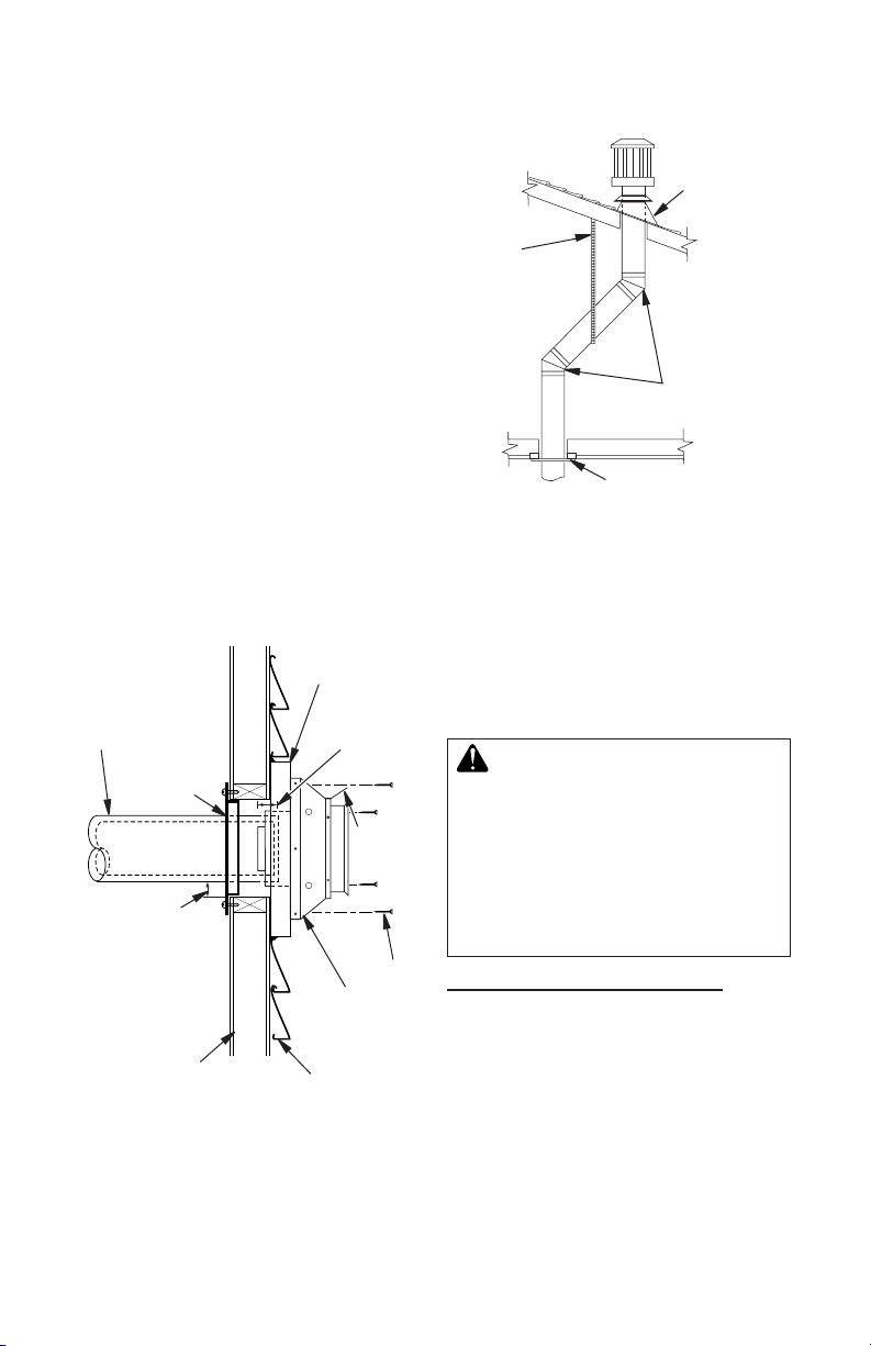
5. For horizontal installation, an optional
siding standoff may be installed between
vent cap and exterior wall. Secure horizontal vent cap to standoff. Secure standoff/
vent cap assembly to wall (see Figure 7).
Do not seal termination to vent pipe. Vent
termination must be removable for service
pipe inspection.
6. For vertical installation, a vertical termination is available. A vertical ue restrictor must be installed into inner collar of
replace as shown in Figure 6, page 10.
When installing a length of pipe for vertical
termination that is over 3 ft., support pipe
every 3 ft. using metal wall straps. Vertical
to horizontal pipe must be kept at a 1 ft. to
4 ft. ratio with a maximum run of no more
than 20 ft.
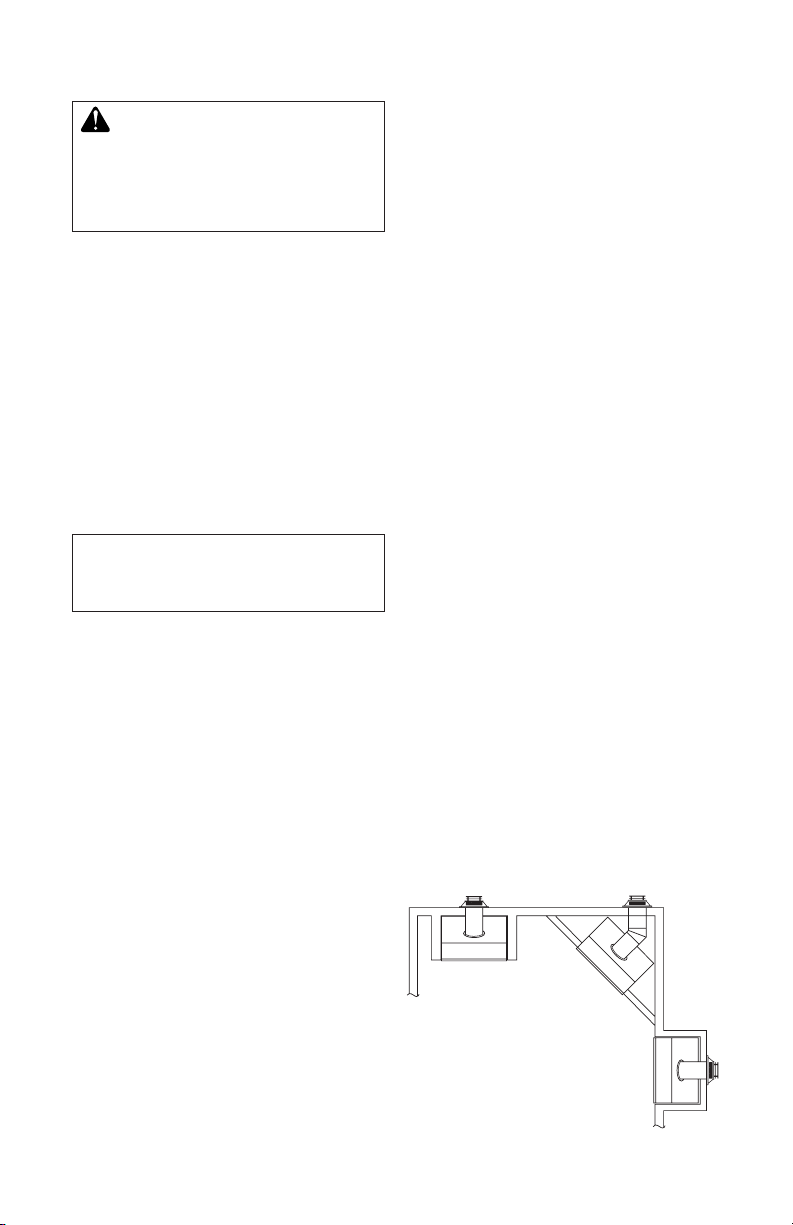
If an offset is necessary in attic to avoid
obstruction, it is important to support vent
pipe every 3 ft. to avoid excessive stress
on elbows and possible separation (see
Figure 8).
Siding Standoff
(Optional)
Direct vent
Pipe
Wall Firestop
Maintain 1"
Minimum
Air Space
Around Outer
Pipe when
Penetrating a
Wall
10 3/4" x 10 3/4"
Framed Opening
Figure 7 - Vent Termination (Horizontal)
Minimum Pipe
Overlap 1 1/4"
Deector
Shield
Screws
Horizontal
Termination
(Vent Cap)
Exterior Wall
with Vinyl
Siding
Roof
Flashing
Wall
Strap
45° Elbows
Ceiling Firestop
Figure 8 - Vertical Termination with
Offset and Wall Strap
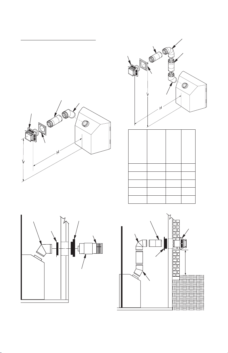
Horizontal Termination Congurations
Figures 9 through 13, pages 12 and 13 show
different congurations and alternatives for
venting with horizontal termination. Each g-
ure includes a chart with critical minimum and
maximum dimensions which MUST be met.
IMPORTANT: Remember that a horizontal
run of venting must have a 1/4" rise for every
12" of run toward termination.
WARNING: Never run vent
downward as this may cause
excessive temperatures which
could cause a re. Operation of
improperly installed and maintained venting system could
result in serious injury, property
damage or loss of life.
GROUND FLOOR INSTALLATION
Recommended Applications:
• Installation using cabinet surrounds
• Through the wall using round or square
termination (up to 12" horizontal pipe)
• NOT FOR CORNER INSTALLATION
125205-01E 11
www.fmiproducts.com
Page 12
INSTALLATION
Continued
TYPICAL CORNER INSTALLATION
Recommended Applications:
• Corner ground oor installation
• Ground oor installation where pipe vents
horizontally through wall (over 12" horizon-
tal pipe)
• Basement installation where one foot
clearance from ground to termination is
possible
Adjustable Pipe
Horizontal High
Wind Square
Termination
Wall
Firestop
Vertical (V) Horizontal (H) Series
323/4" min. 17" max. CD36
363/4" min. 17" max. CD42
45° Elbow
12" Max.
Square Termination
Exterior Portion of
Wall Firestop (Round
Termination Only)
Wall
Firestop
45° Elbow
Round
Termination
Cap
Not to Exceed
Square
Termination
*Note: Ground Floor Corner Venting
(H) Limits
Wall
Firestop
45°
Elbow
CD36 Series
Vertical (V)
Minimum
CD42 Series
Vertical (V)
Minimum
Required
*431/2" *461/4" None 30"
541/2" 571/4" 1 ft. 48"
661/2" 691/4" 2 ft. 60"
781/2" 811/4" 3 ft. 84"
901/2" 931/4" 4 ft. 20'
Not to Exceed
(H) Limits
90° Elbow
90° Elbow
As Required
for (V)
See Chart
for Pipe
Section
Required
Vertical Pipe
Horizontal (H)
Square
Termination
Maximum
Slide Ring
Over Elbow
to Complete
Connection
Round Termination
Figure 9 - Horizontal Termination
Conguration for Square and Round
Terminations
www.fmiproducts.com
Wall
Firestop
45° Elbow
Figure 10 - Horizontal Termination
Conguration for Corner Installation
Using One 90° Elbow
12"
Minimum
125205-01E12
Page 13

INSTALLATION
Continued
HORIZONTAL SYSTEM INSTALLATION USING TWO 90° ELBOWS
The following congurations show the minimum vertical rise requirements for a horizontal
system using two 90° elbows.
Venting with Two 90° Elbows
Vertical (V) Horizontal (H1)
5' min. 2' max. 6' max.
6' min. 4' max. 12' max.
7' min. 6' max. 18' max.
8' min. 8' max. 20' max.
20' max. 8' max. 20' max.
Figure 11 - Horizontal Termination Conguration for Venting Using Two 90° Elbows
Horizontal (H1) +
Horizontal (H2)
45° Elbow
Venting with Two 90° Elbows
Vertical (V) Horizontal (H1) +
5' min. 6' max.
6' min. 12' max.
7' min. 18' max.
8' min. 20' max.
20' max. 20' max.
Figure 12 - Horizontal Termination Conguration for Venting Using Two 90° Elbows
125205-01E 13
Horizontal (H2)
45° Elbow
with Termination at 90° with Fireplace
www.fmiproducts.com
Page 14

INSTALLATION
Continued
INSTALLATION FOR VERTICAL
TERMINATION
Note: Vertical restrictor must be installed
in all vertical installations.
1. Determine the route your vertical venting
will take. If ceiling joists, roof rafters, or
other framing will obstruct venting system,
consider an offset (see Figure 13) to avoid
cutting load bearing members.
Note: Pay special attention to these instal-
lation instructions for required clearances
(air space) to combustibles when passing
through ceilings, walls, roofs, enclosures,
attic rafters, etc. Do not pack air spaces
with insulation. Also note maximum
vertical rise of venting system and any
maximum horizontal offset limitations.
2. Set replace in desired location. Drop a
plumb line down from ceiling to position
of replace exit ue. Mark center point
where vent will penetrate ceiling. Drill a
small locating hole at this point.
Drop a plumb line from inside roof to
locating hole in ceiling. Mark center point
where vent will penetrate roof. Drill a small
locating hole at this point.
Vertical Termination Congurations
Figures 14 through 17 show four different
congurations for vertical termination.
Venting with Two 90° Elbows
Vertical (V)
5' min. 2' max.
6' min. 4' max.
7' min. 6' max.
8' min. 8' max.
20' max. 8' max.
Horizontal (H1) +
45° Elbow
Horizontal (H2)
Note: Install
restrictor into
inner collar of
replace as
shown.
Roof
Flashing
Wall Strap
45° Elbow
Ceiling Firestop
Figure 13 - Offset with Wall Strap and 45°
Elbows
www.fmiproducts.com
Figure 14 - Vertical Venting
Conguration Using Two 90° Elbows
with Two Horizontal Runs (Vertical
Round High Wind Termination Shown)
125205-01E14
Page 15

INSTALLATION
Continued
Venting with One 90° Elbow
Vertical (V) Horizontal (H)
5' min. 2' max.
6' min. 4' max.
7' min. 6' max.
8' min. 8' max.
20' max. 8' max.
45° Elbow
Vertical Venting
V = 40’ max.
45° Elbow
Note: Install restrictor
into inner collar of
replace as shown.
Figure 15 - Vertical Venting Conguration
Using One 90° Elbow (Vertical Round
High Wind Termination Shown)
Venting with Two
90° Elbows
Vertical
5' min. 6' max.
6' min. 12' max.
7' min. 18' max.
8' min. 20' max.
Note: Vertical (V1) +
Vertical (V2) = 40’ max.
45° Elbow
Note: Install restrictor
into inner collar of
replace as shown.
Figure 16 - Vertical Venting Conguration
Using Two 90° Elbows (Vertical Round
High Wind Termination Shown)
(V1)
Horizontal
(H)
Note: Install restrictor
into inner collar of
replace as shown.
Figure 17 - Vertical Venting Conguration
With No Horizontal Run (Vertical Round
High Wind Termination Shown)
ELECTRICAL HOOKUP AND
REMOTE RECEIVER DIAGRAM
An outlet box with two receptacles (see Figure
18) has been supplied for your convenience
and is located inside on the lower right side of
the replace.
Outlet Box
Three-prong Plug
Figure 18 - Duplex Outlet
125205-01E 15
www.fmiproducts.com
Page 16

INSTALLATION
ON
OFF
REMOTE
Continued
The remote control receiver is factory wired
and connected to the convertible gas valve
as shown in Figure 19.
ON/OFF
Knob
Pilot Gas Line
Do Not Kink
Pilot Adjustment
To Pilot
Burner
To Main
Burner
Convertible
Gas Valve
Figure 19 - Remote Control Receiver
Remote
Control
Receiver
GAS SUPPLY TESTING
NOTICE: This section is in-
tended as a guide for qualied
technicians installing gas to the
appliance.
WARNING: Do not connect
appliance before pressure testing gas piping. Damage to gas
valve may result and an unsafe
condition may be created.
Appliance and its individual shutoff valve
must be disconnected from gas supply piping
system during any pressure testing of that
system at test pressures in excess of 1/2 psig
(3.5 kPa).
Appliance must be isolated from gas supply
piping system by closing its individual shutoff
valve during any pressure testing of gas supply piping system at test pressures equal to
or less than 1/2 psig (3.5 kPa).
Gas control valve is secured under rebox.
Two 1/8" ports are provided on gas control
valve for pressure test gauge connections
(see Figure 20).
Inlet
Pressure
Outlet
Pressure
Figure 20 - Gas Control Valve
Flame
Adjustment Knob
GAS LINE HOOK-UP
WARNING: Gas line hookup should be done by your gas
supplier or a qualied service
person.
WARNING: Before you proceed, make sure your gas supply
is OFF.
An equipment shutoff valve has been included
in replace's gas supply system. Consider
installing an extra shutoff valve outside appliance’s enclosure (check local codes), where it
can be accessed more conveniently with a key
through a wall as shown in Figure 21.
In conformance with local codes, route a 1/2"
NPT gas line towards appliance coming in
from bottom, left or right side of replace (see
Figure 22, page 17).
Install a sediment trap between incoming
gas line and gas control box (see Figure 23,
page 17). The sediment trap should extend
down a minimum of 3" (7.62 cm) beyond
center of pipe.
Key
Shutoff
Valve
Extension
Figure 21- Typical Exterior Wall Gas
www.fmiproducts.com
Shutoff Installation
125205-01E16
Page 17

INSTALLATION
1/8"
(0.3 cm)
3/8" - 1/2"
(.95cm-1.3 cm)
Continued
When routing gas line through conduit sleeve,
make sure to repack insulation to ll gaps
between gas line and conduit sleeve. Compounds used on threaded joints of gas piping
shall be resistant to the action of propane or
natural gas. Compounds should be applied
lightly to ensure excess sealant does not
enter gas line.
Complete your gas line installation by connecting incoming gas line to flexible gas
line. Secure tightly with a wrench but do not
over-tighten.
Gas Routing
(Right Side Not Shown)
CHECKING GAS CONNECTIONS
WARNING: All gas piping
and connections must be tested
for leaks after the installation is
completed.
Never use an open ame to
check for a leak. After ensuring
that the gas valve is open apply commercial leak detection
uid to all gas joints. Bubbles
forming show a leak. Correct all
leaks at once.
Do not operate any appliance if
a leak is detected.
Side of
Fireplace
Front Face
Figure 22 - Gas Line Routing
Incoming
1/2" Gas Line
Permitted By
Local Codes
Sediment Trap
(Not Supplied)
Figure 23 - Sediment Trap
PILOT ADJUSTMENT
The pilot or electrode assembly is factory
preset for proper ame height. Alterations
to these settings may have occurred during
shipping and handling. If this is the case, some
minor readjustments may be necessary and
should be done by a qualied service technician. The proper settings for thermopile height
should be at a distance of 3/8" (0.95 cm) to
1/2" (1.27 cm) from pilot ame as shown in
Figure 24.
3" Min.
(7.6 cm)
Figure 24 - Pilot Assembly
125205-01E 17
www.fmiproducts.com
Page 18

INSTALLATION
Lock
Unlock
Continued
REMOVING GLASS PANEL
Glass Door
Figure 26 - Opening Glass Door
CAUTION: Before you proceed, make sure your gas control
valve is in the OFF position.
1. To remove louvers, pull both spring
latches (located in each end of louver)
toward center of appliance at the same
time until disengaged from locating holes.
Repeat for bottom end spring latches (see
Figure 25).
Glass
Locating
Holes
Spring
Latch
Bottom Louver
Figure 25 - Removing Louvers
2. Remove screen rod by removing rod loop
from glass door center bracket. Slide
screen rod to left or right of replace until
one end is free to completely remove
screen from replace.
3. Undo latches located on top and bottom
of rebox (see Figure 26). Carefully swing
door to the left. Glass door is securely
mounted to rebox with 5 screws.
INSTALLING OPTIONAL WIRELESS
HAND-HELD REMOTE CONTROL
MRC SERIES
NOTICE: Use only alkaline batteries (not included).
Installing Remote Receiver
1. Open bottom louver and locate switch
bracket on the right.
2. Remote receiver can be placed in the hole
on the switch bracket or placed on the
oor underneath the rebox, see Figure
27. See remote instructions for further
information.
3. Attach terminal wires to battery.
4. Connect wires from receiver to TH and
TPTH to control valve (see Figure 28).
Remote Receiver
Wire terminals
Receiver
Slide
Button
To Optional
Remote
Accessory
ADJ.
OFF
REMOTE
LEARN
ON
Figure 27 - Remote Receiver
Figure 28 - Control Valve Terminals
www.fmiproducts.com
125205-01E18
Page 19

INSTALLATION
Continued
INSTALLING LOGS, LAVA ROCK
AND GLOWING EMBERS
It is very important to install these logs exactly
as instructed. Do not modify logs. Only use
logs supplied with replace.
Open louvers, remove screen, unlock door
latches, and open glass door. See Removing
Glass Panel, steps 1 to 3, page 18. Install
logs according to instructions for replace
model numbers.
1. Find and place log #1 (rear log) on top of
grate. Make sure notches in bottom of log
t over grate (see Figure 29).
3
Rear Log
Front Log
Metal
Pin
Figure 31 - Installing Log No. 3
4. Place log #4 (right log) onto log landing on
right side of front log as shown in Figure 32.
6
4
Log
Landing
Front
Log
Rear Log
Landing
1
Log
Notches
Grate
Assembly
Figure 29 - Installing Log No. 1
2. Rest log #2 (front log) on pins on front part
of grate (see Figure 30).
2
Metal
Pins
Figure 30 - Installing Log No. 2
3. Place log #3 (crossover log) onto rear and
front logs. Make sure it is seated properly
on surface of rear log and pin on front log
as shown in Figure 31.
125205-01E 19
www.fmiproducts.com
Crossover
Log
Figure 32 - Installing Log No. 4
5. Place log #5 (base log) onto front left part of
grate making sure notch and hole t over
metal pin and prong of grate. See Figure 33.
6. Place log #6 (left log) onto rear log landing
and resting it on top of front log. See Figure
33.
5
Metal
Pin
Grate
Prong
Figure 33 - Installing Logs No. 5 and No. 6
Page 20

INSTALLATION
1
1
2
3
5
6
7
4
Continued
Model CD42M-LS Series
1. Place log #1 (small base log) onto pin
on left side of grate extension (see
Figure 34).
2. Rest left side of log #2 (front log) on top
of log #1 and right side onto pin located
on right side of grate extension (see
Figure 35).
Figure 34 - Installing Log #1, Model
CD42M-LS
3. Place log #3 (rear log) onto pins on rear
of grate (see Figure 36).
4. Place log #4 (crossover log) onto pins from
both logs #2 and #3 (see Figure 37).
5. Place log #5 (top log) onto right pin of front
log (#2) and smooth surface of rear log
(#3). Make sure it is seated properly (see
Figure 38).
Figure 35 - Installing Log #2, Model
CD42M-LS
Figure 37 - Installing Log #4, Model
CD42M-LS
6. Place log #6 (left log) on left pin of front
log (#2) and smooth surface of rear log
(#3). Make sure it is seated properly (see
Figure 39*).
7. Place log #7 (right log) on right pin of top
log (#5). Make sure it is seated properly
(see Figure 39).
Figure 38 - Installing Log #5, Model
CD42M-LS
Figure 36 - Installing Log #3, Model
CD42M-LS
www.fmiproducts.com
Figure 39 - Installing Logs #6 and #7,
Model CD42M-LS
125205-01E20
Page 21

INSTALLATION
Continued
Lava Rock and Ember Material
1. For all models, place lava rock along sides
and front of rebox bottom in areas that
are visible. It is not necessary to use all
lava rock provided.
NOTICE: Do not put lava rock
on or under burner. Placing
lava rock on burner could cause
performance problems.
2. Pull ember material apart into pieces no
larger than a dime. Place loosely and directly onto exposed section of front burner
and along space between burner and grate
prongs. These will create glowing ember ap-
pearance as ame touches ember material.
Do not block air slots by using too much
ember material in one area. It is not necessary to use all ember material provided.
3. When lava rock and ember material are
in place, close and latch glass door and
secure louvers in place.
WARNING: The glass door
must be securely in place before
operating replace. Do not operate replace if glass is missing
or broken.
DECORATIVE FACING
Any noncombustible material may be used as
facing (glass, tile, brick, etc.) as long as the
proper clearances are observed (see Clear-
ances to Combustibles, page 6). Louvered
openings must not be obstructed and upper
and lower panels must remain accessible for
service. Use only heat-resistant, noncombustible mortar or adhesive when securing
decorative facing materials.
OPTIONAL FACE EXTENSION
(AVAILABLE FE-36M FOR MODEL
CD36M-LS)
Front face extension would add 3 1/2" to width
and 3/4" to height of replace face.
To install face extension:
1. Remove existing screws from front face
assembly as shown in Figure 40.
2. Align holes on top face extension with
holes on top side of front face assembly
and secure with screws previously removed (see Figure 40).
125205-01E 21
www.fmiproducts.com
3. Align holes on right face extension with
holes on right side of front face assembly
and secure with screws previously removed (see Figure 34). Do the same for
left side.
4. Secure top face extension with left and
right face extensions with two sheet metal
screws (see Figure 34).
Top Face
Extension
Side Face
Extensions
Figure 40 - Front Face Extension, Model
CD36M-LS Only
Page 22

INSTALLATION
Continued
INSTALLING BLOWER ACCESSORY
NOTICE: If installing blower in
an existing replace with gas
connections, shut off gas supply
and disconnect replace from
gas supply. Contact a qualied
service person to do this.
WARNING: If there is a duplex
electrical outlet installed in the
right side of the bottom of the
replace base area, be sure that
the electrical power to the outlet is
turned off before proceeding with
blower installation. Failure to do
this may result in serious injury.
Model BK Installation
Follow all instructions provided in blower
accessory kit.
1. Attach power cord to blower motor by
rmly pushing two female terminals at end
of power cord onto two spade terminals
on blower motor (see Figure 41).
2. Attach green ground wire from power cord
to blower housing using screw provided
(see Figure 41). Tighten screws securely.
3. Place blower against lower rear wall of
rebox outer wrapper with exhaust port
directed upward. Blower will t inside back
opening and be held in position against back
wall by magnets (see Figure 41).
4. Be certain that all wire terminals are
securely attached to terminals on blower
motor and that screw retaining green
ground wire is tight.
5. Mount speed control box to switch bracket
by placing plastic control shaft forward
through round opening in switch bracket
(see Figure 42).
6. While supporting speed control, secure
control shaft with lock nut by pushing
and turning lock nut with pliers clockwise
until it is tight against front panel. Place
provided control knob on shaft.
7. Turn on power to duplex outlet if previously
turned off per warning in this column.
8. Plug in blower power cord.
a. If your rebox is installed as a free-
standing unit with an accessory mantel,
determine whether power cord will exit
left side or right side of rebox. Route
power cord through exit hole and plug
power cord into a wall receptacle near
rebox.
b. If your rebox installation is recessed
and/or pre-wired, plug power cord into
duplex outlet provided. Refer to your
rebox owner’s manual for instructions
on wiring duplex outlet.
Lower Firebox
Cavity
Side View
Spade
Terminals
Figure 41 - Blower Model BK
Switch
Bracket
Speed Control
Locknut
Figure 42 - Attaching Speed Control to
Blower Location
Magnetic
Strips
Screw
Exhaust Port
Control Shaft
Blower
Plug-In
Duplex Outlet (Located
beneath rebox oor
against lower right
outside wall)
Firebox
CAUTION: Never touch the
blower wheel while in operation.
www.fmiproducts.com
125205-01E22
Page 23

INSTALLATION
Variable
Fa
n
Switc
h
WhiteWhite
Black
Gre
en
On
110/11
5
V.A.C.
Blowe
r
M
otor
Black
Black
Black
Off
Blue
Variable
Fan Switch
Fan Switch
(N.O.)
Green
White
On
110/115
V.A.C.
Blower
Motor
Black
Off
1
2
Black
WALL SWITCH
Continued
9. Check to make sure that power cord is
completely clear of blower wheel and
that there are no foreign objects in blower
wheel. Turn blower on and check for operation. Turn blower off by turning knob
fully counterclockwise before continuing.
10. Peel off backing paper and stick supplied
wiring diagram decal on rebox bottom
approximately 12" in front of blower (see
Figure 43).
BLOWER WIRING DIAGRAM
Wiring Diagram Decal
12" in Front of Blower
Figure 43 - Location of Wiring Diagram
Decal (Model May Vary From Illustration)
DO NOT
TO 120V
CONNECT
REPLACE FACTORY
WIRING WITH 105°C
EQUIVALENT OR
HIGHER RATING
18 GA. RED/WHITE
EXTERNAL WIRING
USE ONLY CLASS 2
THERMOSTAT WIRE
THERMOPILE
PILOT
BURNER
RED
PILOT SAFETY VALV E
WHITE
N
O
TP
TH
TH/TP
O
F
F
T
P
I
L
O
PILOT
GAS
IGNITOR
LINE
Figure 44 - Blower Wiring Diagram for
Thermostat-Controlled Models
Figure 45 - Millivolt Ignition Wiring Diagram
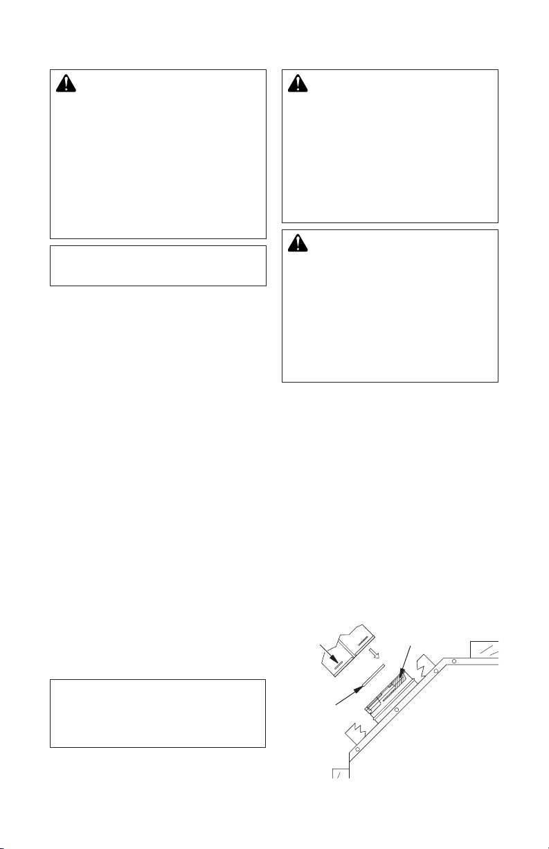
BURNER FLAME ADJUSTMENT
Burner ame adjustment (shutter opening)
has been factory preset (for natural gas) to
proper air-to-gas ratio. This ratio results in an
even, clean burning ame across burner (see
Figure 46, page 24).
If adjustment is necessary, you can restore
proper ame setting by loosening air shutter
screw and rotating air shutter until proper
setting is achieved (see Figure 47, page 24).
Correct shutter openings are 3/16'' for natural
gas and fully open for propane/LP gas.
Model NG LP NG LP
CD36M-LS 0.188" Max — —
CD42M-LS 0.188" 0.313" 0.188" 0.500"
125205-01E 23
Tube Burner Pan Burner
www.fmiproducts.com
WARNING: Improper installa-
tion, adjustment, alteration, ser-
vice or maintenance can cause
injury or property damage. Refer
to this manual for assistance.
Consult a qualied installer for
additional information.
SUPPLY
MAIN GAS
INCOMING
Page 24

BURNER FLAME
ADJUSTMENT
Continued
CORRECT
INCORRECT
CLOSE
SHUTTER
INCORRECT
OPEN
SHUTTER
Adjustment
Screw
Firebox
Bottom
Long, Blue Flame with Yellow Tips
Short, Sharp, Blowing Flame
Long, Uneven, Yellow Flame
Figure 46 - Burner Flame Patterns
Burner Pan
Manifold
Air Shutter
Opening
Burner
Gas Line
Adjustment Screw
Air Shutter
Opening
Firebox
Bottom
Burner
Gas Line
Figure 47 - Air Shutter Adjustments
Burner
Tube
Manifold
OPERATION
OPERATION GUIDELINES
• When used for the rst time, replace may
emit a slight odor for about 16 to 24 hours.
This is normal and is due to “curing” of logs
and “burn-in” of internal paint and lubricant
used in manufacturing process.
• Keep compartments, logs, burners and
area surrounding logs clean by vacuuming
and brushing at least twice a year or as
necessary.
• Turn off gas and remote switch before
servicing appliance. Any safety screen or
guard removed for servicing the replace
must be replaced prior to operation.
• Have a qualied agency periodically inspect
vent system at the start of each heating
season for any obstruction which will hinder
its normal operation. Never obstruct ow
of combustion and ventilation air. Keep
front of replace clear of all obstacles and
materials.
FOR YOUR SAFETY
READ BEFORE LIGHTING
WARNING: If you do not fol-
low these instructions exactly,
a re or explosion may result
causing property damage, personal injury or loss of life.
A. This appliance has a pilot which must
be lighted by hand. When lighting the pilot, follow these instructions exactly.
B. BEFORE LIGHTING smell all around
the appliance area for gas. Be sure to
smell next to the oor because some
gas is heavier than air and will settle
on the oor.
WHAT TO DO IF YOU SMELL GAS
• Do not try to light any appliance.
• Do not touch any electric switch; do
not use any phone in your building.
• Immediately call your gas supplier
from a neighbor’s phone. Follow the
gas supplier’s instructions.
• If you cannot reach your gas supplier,
call the re department.
C. Use only your hand to push in control
knob. Never use tools. If the knob will
not push in or slide by hand, don’t
try to repair it, call a qualied service
technician. Force or attempted repair
may result in a re or explosion.
www.fmiproducts.com
125205-01E24
Page 25

OPERATION
Continued
D. Do not use this appliance if any part has
been under water. Immediately call a
qualied service technician to inspect
the appliance and to replace any part of
the control system and any gas control
which has been under water.
LIGHTING
INSTRUCTIONS
1. STOP! Read safety information in column
1 before proceeding.
2. Turn off all electrical power to appliance.
3. Open bottom access louver.
4. Slide remote selector to OFF position.
5. Make sure manual shutoff valve is fully open.
6. Push in gas control knob slightly and turn
clockwise to OFF.
7. Wait ve (5) minutes to clear out any gas.
Then smell for gas, including near oor. If
you smell gas, STOP! Follow B in safety
information in column 1. If you don’t smell
gas, go to next step.
8. Visually locate pilot assembly by main burner.
9. Turn knob on gas control counterclockwise to PILOT.
10. Push control knob all the way in and hold.
Immediately light pilot by pressing red ig-
nitor button until ame appears. Continue
to hold control knob in for about one (1)
minute after pilot is lit. Release knob and
it will pop back up. Pilot should remain lit.
If it goes out, repeat steps 6 through 10.
• If knob does not pop out when released,
stop and call service technician or gas
supplier.
• If pilot will not stay lit after several tries,
turn gas control knob to OFF and call
your service technician or gas supplier.
11. Turn gas control knob counterclockwise
to ON. Knob can be turned to ON
only if control knob is popped out.
12. Set HI-LO knob to desired setting.
13. Slide remote sector switch to REMOTE
position to operate using remote control.
Selector switch must be in the ON position
to operate manually.
Position
Indicator
14. Turn on all electric power to appliance.
Note: It is recommended that you maintain
gas control knob in the full OFF position during
lengthy periods of seasonal non use.
Piezo Ignitor
Thermocouple
Figure 49 - Pilot
Pilot Burner
Thermopile
TO TURN OFF GAS
TO APPLIANCE
1. Turn off wall switch, if installed.
2. Turn off all electric power to appliance if
service is to be performed.
3. Open bottom access louver.
4. Slide selector switch to OFF position.
5. Push in gas control knob slightly and turn
clockwise to OFF. Do not force.
6. Close bottom access louver.
OPTIONAL HAND-HELD
REMOTE OPERATION
Note: All remote control accessories must be purchased separately (see Accessories, page 38).
Follow instructions included with remote control.
NOTICE: You must light the pilot
before using the hand-held remote control unit. See Lighting
Instructions.
After lighting, let pilot ame burn for about
one minute. Turn control knob to ON posi-
tion. Adjust ame adjustment knob anywhere
between HI and LO. Slide selector switch to
the REMOTE position.
Note: The burner may light if hand-held remote was on when selector switch was last
turned off. You can now turn burner on and off
with hand-held remote control unit.
IMPORTANT: Do not leave the selector switch
in the REMOTE or ON position when the pilot
is not lit. This will drain the battery.
Gas Control
Knob
Figure 48 - Control Knob in Pilot Position
125205-01E 25
HI/LO Knob
www.fmiproducts.com
Page 26

GAS CONVERSION
The conversion kit is packaged with the unit.
Please check the contents before beginning
this conversion.
Pilot Hood
WARNING: Before proceeding, make sure the gas control
valve is in the OFF position and
all electrical power to the appliance is turned off.
CONVERTING PILOT
1. Wait ve (5) minutes to clear out any gas.
Smell for any gas odor, especially near the
oor. If any gas odor is present, STOP!
See For Your Safety Read Before Lighting
on page 24.
2. Locate latch on louver assembly. Remove
top and bottom louvers by pulling spring
latches toward center of replace simultaneously until they are disengaged from
locating holes.
3. Undo latches located on top and bottom
of rebox and swing door to fully open
position.
4. Carefully remove log set and ember material from burner and place them aside in
a safe place.
5. Replace main burner orifice with
burner orifice included in conversion
kit. (Model CD42M-LS series contains
two burner orifices).
6. Locate air shutter at end of burner manifold. (End of tube burner for CD42M-LS
series). Loosen screw and adjust air shutter to proper setting (see Burner Flame
Adjustment, page 23). Retighten screw.
7. Remove pilot hood by pulling up until it
disengages from barrel. Do not remove
the retainer clip (see Figure 50).
8. Remove pilot orice from inside barrel using
a 5/32" allen wrench to unscrew orice.
9. Replace pilot orice with LP orice supplied
with this kit. The number 30 is stamped on
the sleeve for identication. Insert small
end of new pilot orice into barrel and
thread until tight with the allen wrench.
10. Line up notch on pilot hood to the positioning tab on barrel receiver and snap back
into position.
IMPORTANT: Be careful not to bend or kink
aluminum tubing during conversion. Make
sure pilot hood and orice are properly mated
and aligned after nishing this conversion.
www.fmiproducts.com
Pilot Orice
Barrel Clip
5/32" Allen
Wrench
Pilot
Bracket
Figure 50 - Converting Pilot
CONVERTING CONTROL VALVE
Convert gas control valve by swapping out
valve regulator portion of gas valve.
1. Using a TORX T20 or a slotted screwdriver, remove and discard three mounting screws, pressure regulator tower
and diaphragm/spring components (see
Figure 51).
Mounting
Screws
Diaphragm/
Spring
Components
Figure 51 - Removing Parts for Gas
Control Valve Conversion
LO
HI
Pressure
Regulator
Tower
O
F
F
P
N
I
L
O
O
T
125205-01E26
Page 27

GAS CONVERSION
HI
LO
O
F
F
P
I
L
O
T
O
N
Continued
2. Insure that rubber gasket is properly
positioned on new pressure regulator
assembly. Install new pressure regulator
assembly to valve using new mounting
screws supplied with kit. Tighten screws
securely (approximately 25 in/lb). See
Figure 52.
3. Install identication label enclosed with
gas valve regulator to valve body where
it can easily be seen (see Figure 52).
Mounting
Screws
CLEANING AND
MAINTENANCE
WARNING: Turn off replace
and let cool before cleaning.
CAUTION: You must keep
control areas, burners and
circulating air passageways of
replace clean. Inspect these
areas of replace before each
use. Have replace inspected
yearly by a qualied service
person. Fireplace may need
more frequent cleaning due to
excessive lint from carpeting,
bedding material, pet hair, etc.
GLASS DOOR
Rubber
Gasket
Identication
Label
Figure 52 - Installing New Parts for Gas
Control Valve Conversion
WARNING: The conversion
kit must be installed by a qualied service technician in accor-
dance with the manufacturers
instructions and all applicable
codes and requirements of the
authority having jurisdiction. If
any information is these instructions is not followed correctly,
a re, explosion or production
of carbon monoxide may result
causing property damage, personal injury or loss of life. The
qualied service technician is
responsible for the proper installation of this conversion kit.
WARNING: Handle glass
door panel with care. Do not
strike, slam or otherwise abuse
glass. Do not operate replace
with the glass door unlatched,
removed, cracked or broken.
WARNING: Do not use
abrasive cleaners as this may
damage glass. Use a nonabrasive household glass cleaner to
clean glass. Do not clean glass
when hot.
Glass must be cleaned periodically. During
start-up it is normal for condensation to form
on the inside of the glass causing lint, dust
and other airborne particles to cling to the
glass surface. During initial start-up a slight
lm may form on the glass due to paint curing.
The glass should be cleaned several times
with a non-ammonia, nonabrasive household
cleaner and warm water after the rst two
weeks of operation. Thereafter, clean the
glass two or three times during each heating season, depending on the usage and
circumstances present. Refer to Removing
Glass Panel, page 18 of this manual when
removing glass door for cleaning.
125205-01E 27
www.fmiproducts.com
Page 28

CLEANING AND MAINTENANCE
Continued
WARNING: Only parts supplied by the manufacturer should
be used when replacing broken
or damaged glass door panel
(see Replacement Parts, page
33). This glass door panel is
a complete unit. No substitute
materials may be used.
CAUTION: Wear gloves and
safety glasses while handling or
removing broken glass. Do not
remove if glass is hot. Keep children and pets away from glass.
If glass has been broken, carefully remove
glass door (see Removing Glass Panel, page
18). Vacuum all glass pieces with a shop vac.
CAUTION: Do not vacuum if
pieces are hot.
Use only the tempered glass door replace-
ment intended for this replace (see Replacement Parts, page 33 for detail on ordering).
No substitutions may be made. See Removing Glass Panel, page 18 for instructions for
replacing glass door.
WARNING: Do not operate
replace with the glass door
unlatched, removed, cracked
or broken.
LOGS
• If you remove logs for cleaning, refer to
Installing Logs Lava Rock and Glowing
Embers, page 19, to properly replace logs.
• Use a vacuum cleaner to remove any
carbon buildup on logs.
• Replace log(s) if broken. See Replacement
Parts on page 33.
•
Replace ember material periodically
as needed. See Replacement Parts on
page 33.
VENTING SYSTEM
Conduct annual inspection of the venting
system following these guidelines:
1. Check areas of venting system that are
exposed to the weather for corrosion (rust
spots or streaks and, in extreme cases,
holes). Have these items replaced im-
mediately by a qualied service person.
2. Remove the vent cap and shine a ash-
light into the vent. Remove any foreign
material.
3. Check for evidence of excessive con-
densation. Continuous condensation can
cause corrosion of caps, pipes and ttings
and can be caused by having excessive
lateral runs, too many elbows or exterior
portions of the system being exposed to
cold weather.
4. Inspect joints to verify that no pipe section
or tting has been disturbed and loosened. Check mechanical supports such
as wall straps for rigidity.
PILOT AND BURNERS
• Remove ember material before cleaning
burners and replace when cleaning is
complete.
• Burner and controls should be cleaned with
compressed air to remove dust, dirt or lint.
• Use a vacuum cleaner or small, soft bristled
brush to remove excess dust, dirt or lint.
www.fmiproducts.com
125205-01E28
Page 29

TROUBLESHOOTING
WARNING: Turn off replace and let cool before servicing. Only
a qualied service person should service and repair replace.
WARNING: Turn off replace and let cool before servicing. Only
a qualied service person should service and repair replace.
OBSERVED PROBLEM
Pilot will not stay lit
Pilot lit but no ame on
burner
POSSIBLE CAUSE
1. Defective thermocouple
1. Remote or wires defective
2. Thermopile not generating
sufcient millivoltage
3. Plugged burner orice
REMEDY
1. Check pilot ame. It must
impinge on thermocouple
2. Clean or adjust pilot for
maximum ame impingement on thermocouple
3. Ensure connection between
valve and thermocouple are
tight and secure
4. Check thermocouple with
millivolt meter. Take reading
at thermocouple terminals
of gas valve with remote
control off. It should read
18 millivolts minimum. Replace faulty thermocouple if
reading is below specied
minimum
1. Check remote wires for
proper connections. Place
jumper wire across terminals at remote control.
If burner comes on, replace remote. If okay, place
jumper wire across remote
control at valve. If burner
comes on, wires are faulty
or connections are bad
2. Check thermopile with millivolt meter. Take reading at
thermopile terminals of gas
valve with remote control
off. It should read 325 millivolts minimum. Replace
thermopile if reading is
below specied minimum
3. Check burner orifice for
stoppage and remove
Frequent pilot outage
125205-01E 29
1. Pilot ame may be too low
or blowing (high) causing
safety pilot to “drop out”
www.fmiproducts.com
1. Clean and/or adjust pilot
ame for maximum ame
impingement on thermocouple
Page 30

OBSERVED PROBLEM
Delayed ignition burner
TROUBLESHOOTING
Continued
POSSIBLE CAUSE
1. Manifold pressure is too
low
2. Burner porting or orifice
clogged
REMEDY
1. Contact local propane/LP
or natural gas company
2. Clean burner (see Clean-
ing and Maintenance,
page 27) or replace burner
orice
Burner backfiring during
combustion
Slight smoke or odor during
initial operation
1. Burner orice is clogged or
damaged
2. Damaged burner
3. Gas regulator defective
1. Residues from manufacturing processes and logs
curing
1. Clean burner (see Clean-
ing and Maintenance,
page 27) or replace burner
orice
2. Replace damaged burner
3. Replace gas control
1. Problem will stop after a
few hours of operation
www.fmiproducts.com
125205-01E30
Page 31

OBSERVED PROBLEM
Fireplace produces a whistling noise when burner is lit
TROUBLESHOOTING
Continued
POSSIBLE CAUSE
1. Turning gas control knob to
HI position when burner is
cold
2. Air in gas line
3. Dirty or partially clogged
burner orice
REMEDY
1. Turn gas control knob to
LO position and let warm
up for a minute
2. Operate burner until air is
removed from line. Have
gas line checked by local
propane/LP or natural gas
company
3. Clean burner (see Clean-
ing and Maintenance,
page 27) or replace burner
orice
Glass soots
Fireplace produces a clicking/
ticking noise just after burners
are lit or shut off
Remote does not function
Dark residue on logs or inside
of replace
1. Debris around burner air
mixer
2. Improper vent conguration
1. Metal expanding while
heating or contracting
while cooling
1. Battery is not installed or
battery power is low
1. Air holes at burner inlet
blocked
2. Burner ame holes blocked
3. Improper venting or excessive blockage
4. Excessive amounts of
embers and pan material
1. Inspect the opening at
the base of the burner by
removing log/grate assembly to see that it is
NOT packed with any type
of material for log/grate
removal
2. Check vent conguration
specications (see Venting
Installation, page 10)
1. This is normal. If noise is
excessive, contact quali-
ed service person
1. Replace 9-volt batteries
in receiver and hand-held
remote control
1. Clean out air holes at
burner inlets. Periodically
repeat as needed
2. Remove blockage or replace burner
3. Have vent system inspected, including termination
cap. Remove any restrictions or obstruction
4. Clear excess embers until
a minimum gap of 1/2"
remains under the grate
125205-01E 31
www.fmiproducts.com
Page 32

TROUBLESHOOTING
Continued
WARNING: If you smell gas
• Shut off gas supply.
• Do not try to light any appliance.
• Do not touch any electrical switch; do not use any phone in your
building.
• Immediately call your gas supplier from a neighbor’s phone. Follow the gas supplier’s instructions.
• If you cannot reach your gas supplier, call the re department.
OBSERVED PROBLEM
Fireplace produces unwanted
odors
Fireplace shuts off in use
Gas odor even when control
knob is in OFF position
POSSIBLE CAUSE
1. Gas leak. See Warning
statement above
1. High or gusting winds
2. Low line pressure
3. Pilot is partially clogged
4. Inner vent pipe leaking exhaust gasses into system
5. Glass too loose and air
tight gasket leaks in corners after usage
6. Bad thermopile or thermocouple
7. Improper vent cap installation
1. Gas leak. See Warning
statement above
2. Control valve defective
REMEDY
1. Locate and correct all
leaks (see Checking Gas
Connections, page 17)
1. Fireplace has been tested
for up to 40 mph winds.
However, extreme conditions may occur. See Light-
ing Instructions on page 25
2. Contact local propane/LP
or natural gas company
3.
Clean pilot (see Cleaning
and Maintenance, page 27)
4. Locate and correct all
leaks (see Checking Gas
Connections, page 17)
5. Tighten glass
6. Replace faulty component
7. Check for proper installation and freedom from
debris or blockage
1. Locate and correct all
leaks (see Checking Gas
Connections, page 17)
2. Replace control valve
Gas odor during combustion
1. Gas leak. See Warning
statement above
www.fmiproducts.com
1. Locate and correct all
leaks (see Checking Gas
Connections, page 17)
125205-01E32
Page 33

SPECIFICATIONS
CD36M-LS Natural Gas
• Rating: 15,000/22,000 Btu/Hr
• Gas Type: Natural Gas Only
• Ignition: Piezo
• Manifold Pressure: 3.5" W.C.
• Orice Size (Main Burner): #43 DMS
• Minimum Inlet Supply Pressure: 4.5" W.C.
• Firebox Dimensions (HxWxD) (Flanges and
Standoffs Not Included in Measurements):
36 1/8" x 41 ¼" x 23 ½"
CD36M-LS Propane/LP Gas
• Rating: 14,000/20,000 Btu/Hr
• Gas Type: Propane/LP Gas Only
• Ignition: Piezo
• Manifold Pressure: 10" W.C..
• Orice Size (Main Burner): #55 DMS
• Minimum Inlet Supply Pressure: 11" W.C.
• Firebox Dimensions (HxWxD) (Flanges and
Standoffs Not Included in Measurements):
36 1/8" x 41 ¼" x 23 ½"
CD42M-LS Natural Gas
• Rating: 25,000/35,000 Btu/Hr
• Gas Type: Natural Gas Only
• Ignition: Piezo
• Manifold Pressure: 3.5" W.C.
• Orice Size (Main Burner): #47 DMS
• Minimum Inlet Supply Pressure: 4.5" W.C.
• Firebox Dimensions (HxWxD) (Flanges and
Standoffs Not Included in Measurements):
40" x 48" x 23 ½"
CD42M-LS Propane/LP Gas
• Rating: 23,000/33,000 Btu/Hr
• Gas Type: Propane/LP Gas Only
• Ignition: Piezo
• Manifold Pressure: 10" W.C..
• Orice Size (Main Burner): #55 DMS
• Minimum Inlet Supply Pressure: 11" W.C.
• Firebox Dimensions (HxWxD) (Flanges and
Standoffs Not Included in Measurements):
40" x 48" x 23 ½"
REPLACEMENT PARTS
Note: Use only original replacement parts.
This will protect your warranty coverage for
parts replaced under warranty.
Contact authorized dealers of this product.
If they can’t supply original replacement
part(s), call FMI PRODUCTS, LLC at
1-866-328-4537 for referral information. A
list of authorized dealers can be found by
visiting www.fmiproducts.com.
When calling have ready:
• model and serial numbers of your replace
• the replacement part number
SERVICE HINTS
When Gas Pressure Is Too Low
• pilot will not stay lit
• burners will have delayed ignition
• replace will not produce specied heat
• propane/LP gas supply might be low (pro-
pane/LP units only)
You may feel your gas pressure is too low. If
so, contact your local gas supplier.
TECHNICAL SERVICE
You may have further questions about
installation, operation, or troubleshooting.
If so, contact FMI PRODUCTS, LLC at
1-866-328-4537.
When calling please have your model and
serial numbers of your replace ready.
You can also visit FMI PRODUCTS, LLC's
web site at www.fmiproducts.com.
125205-01E 33
www.fmiproducts.com
Page 34

6
7
19
18
10
23
24
34
2
17
8
21-2
21-6
21-4
21-5
21-3
21-1
1
9
16
3
14
4
20
5
15
13
11
35
36
22 37
39
38
25
12
26
30
27
28
29
33
31
32
MODEL CD36M-LS
PARTS
www.fmiproducts.com
125205-01E34
Page 35

MODEL CD36M-LS
PARTS
KEY
NO. PART NO. DESCRIPTION QTY.
1 ** Firebox Assembly 1
2 ** Face Weldment 1
3 110994-01 Door Assembly 1
4 108011-01 Top Panel Assembly Louver 1
5 108011-02 Bottom Panel Assembly Louver 1
6 ** Fireplace Top 1
7 **** Fireplace Top Insulation 1
8 ** Fireplace Surround 1
9 111878-01 Burner Assembly 1
10 110985-01 Burner Base Gasket 1
11 — Right Face Extension 1
12 — Left Face Extension 1
13 — Top Face Extension 1
14 11418 Push-On Nut 2
15 12105 Screen 2
16 13113 Screen Rod 1
17 ** Electrical Duct Assembly 1
18 ** Gas Knock-Out Cover 2
19 ** Gas Conduit Assembly 1
20 109082-01 Heat Shield 1
21 109006-01 Log Set 1
21-1 110182-01 Front Log (Log 2) 1
21-2 109007-01 Rear Log (Log 1) 1
21-3 109009-01 Base Log (Log 5) 1
21-4 109008-01 Crossover Log (Log 3) 1
21-5 107348-01 Left Top Log (Log 6) 1
21-6 107347-01 Right Top Log (Log 4) 1
22 11102 Screw #8-32 x 3/8 PPH Zinc 2
23 11105 Screw #10 x 1/2 Zinc 9
24 11179 Screw #10-24 x 1/4 Zinc 4
25 11237 Screw Trilab M4 x 8 mm 1
26 14389 HI-LO Sit Valve (Natural Gas) 1
27 097159-04 Piezo Ignitor 1
28 14500 Brass Fitting 2
29 111288-02 Flexible Connector 1
30 14511 Ignitor Bracket 1
31 14528 Brass Elbow Fitting 1
32 104506-01 Orice #43 1
33 110984-01 Aluminum Tubing Assembly 1
34 26808 Valve Bracket 1
35 26827 Switch Bracket 1
36 111911-01 Grate Base 1
37 110987-01 Burner Tube 1
38 108084-02 Pilot Assembly (Natural Gas) 1
39 ** Burner Base Assembly 1
** Not a eld replaceable part.
PARTS AVAILABLE NOT SHOWN
101142-01SA Lava Rock 1
110251-01 Micro Switch Assembly 1
112033-01 Gas Conversion Kit 1
125205-01E 35
www.fmiproducts.com
Page 36

37
23
41
42
38
22
39
32
31
33
28
26
25
29
24
34
35
40
36
30
27
28
6
7
19
18
10
12
2
11
17
8
20
1
4
13
16
3
14
15
5
15
9
212
21-3
21-6
21-7
21-5
21-4
21-1
MODEL CD42M-LS
PARTS
www.fmiproducts.com
125205-01E36
Page 37

PARTS
MODEL CD42M-LS
KEY
NO.
PART NO.
1 ** Firebox Assembly 1
2 ** Face Weldment 1
3 108328-01 Door Assembly 1
4 108331-01 Top Panel Assembly Louver 1
5 108331-03 Bottom Panel Assembly Louver 1
6 ** Fireplace Top 1
7 ** Fireplace Top Insulation 1
8 ** Fireplace Surround 1
9 108329-05 Burner Assembly 1
10 108374-01 Burner Base Gasket 1
11 111297-01 Rear Refractory 1
12 111298-01 Right Refractory 1
13 111299-01 Left Refractory 1
14 11418 Push-On Nut 2
15 107840-01 Screen 2
16 108455-01 Screen Rod 1
17 110037-01 Electrical Duct Assembly 1
18 ** Gas Knock-Out Cover 2
19 ** Gas Conduit Assembly 1
20 ** Heat Shield 1
21 108778-01 Log Set 1
21-1 109402-01 Small Base Log (Log 1) 1
21-2 109396-01 Front Log (Log 2) 1
21-3 109397-01 Rear Log (Log 3) 1
21-4 109398-01 Crossover Log (Log 4) 1
21-5 109399-01 Top Center Log (Log 5) 1
21-6 109400-01 Top Left Log (Log 6) 1
21-7 109401-01 Top Right Log (Log 7) 1
22 11102 Screw #8-32 x 3/8 PPH Zinc 2
23 11105 Screw #10 x 1/2 Zinc 9
24 11179 Screw #10-24 x 1/4 Zinc 4
25 11237 Screw Trilab M4 x 8 mm 1
26 14389 HI-LO Sit Valve (Natural Gas) 1
27 14492 Piezo Ignitor 1
28 14500 Brass Fitting 2
29 14253 Flexible Connector 1
30 14511 Ignitor Bracket 1
31 14528 Brass Elbow Fitting 1
32 104506-25 Orice 1
33 14544 Aluminum Tubing Assembly 1
34 26808 Valve Bracket 1
35 26827 Switch Bracket 1
36 108346-01 Grate Base 1
37 108376-01 Burner Tube 1
38 108084-02 Pilot Assembly (Natural Gas) 1
39 108755-01 Pilot Bracket 1
40 108373-01 Burner Base Assembly 1
41 108330-01 Burner Pan Assembly 1
42 104506-24 Orice 1
25487 Lava Rock 1
110251-01 Micro Switch Assembly 1
27253 Notice Label 1
111007-01 Gas Conversion Kit 1
** Not a eld replaceable part.
125205-01E 37
DESCRIPTION QTY.
PARTS AVAILABLE NOT SHOWN
www.fmiproducts.com
Page 38

ACCESSORIES
NOTE:
be available for all
All accessories may not
replace
models.
Purchase these accessories from an au-
thorized dealer. If they can not supply these
accessories call FMI PRODUCTS, LLC at
1-866-328-4537. A list of authorized dealers
can be found.
THERMOSTATICALLY CONTROLLED BLOWER KIT - BKT
Provides better heat distribution Blower turns
off and on automatically, as needed. Complete installation and operating instructions
included in this manual.
ON
OFF
REMOTE CONTROL KIT MRC
Allows the replace to be turned on and off
conveniently.
WALL MOUNTED ON/OFF SWITCH
GWMS2
Allows burner system to be turned on and off
with a wall switch.
BRICK LINER KITS
BL36D - 36" Warm Red Traditional
Stacked Brick
BL36DH - 36" Warm Red Herringbone
Brick
FACE EXTENSION - FE-36M
124190-01 Right Face Extension
124191-01 Left Face Extension
124192-01 Top Face Extension
www.fmiproducts.com
125205-01E38
Page 39

NOTES
_____________________________________________________
______________________________________________________
______________________________________________________
______________________________________________________
______________________________________________________
______________________________________________________
______________________________________________________
______________________________________________________
______________________________________________________
______________________________________________________
______________________________________________________
______________________________________________________
______________________________________________________
_____________________________________________________
______________________________________________________
______________________________________________________
______________________________________________________
______________________________________________________
______________________________________________________
______________________________________________________
______________________________________________________
______________________________________________________
125205-01E 39
www.fmiproducts.com
Page 40

WARRANTY
KEEP THIS WARRANTY
Model (
located on product or identication tag
Serial No. (
located on product or identication tag
Date Purchased __________________________
Keep receipt for warranty verication.
FMI PRODUCTS, LLC LIMITED WARRANTIES
Standard Warranty: FMI PRODUCTS, LLC warrants this new product and any parts thereof to be free from defects
in material and workmanship for a period of two (2) years from the date of rst purchase from an authorized dealer
provided the product has been installed, maintained and operated in accordance with FMI PRODUCTS, LLC’s
warnings and instructions.
For products purchased for commercial, industrial or rental usage, this warranty is limited to 90 days from the date
of rst purchase.
Limited Warranty: FMI PRODUCTS, LLC warrants factory reconditioned products and any parts thereof to be
free from defects in material and workmanship for 30 days from the date of rst purchase from an authorized dealer
provided the product has been installed, maintained and operated in accordance with FMI PRODUCTS, LLC’s
warnings and instructions.
The following terms apply to all of the above warranties:
Always specify model number and serial number when contacting the manufacturer. To make a claim under this
warranty the bill of sale or other proof of purchase must be presented.
This warranty is extended only to the original retail purchaser when purchased from an authorized dealer, and only
when installed by a qualied installer in accordance with all local codes and instructions furnished with this product.
This warranty covers the cost of part(s) required to restore this product to proper operating condition and an allow-
ance for labor when provided by a FMI PRODUCTS, LLC Authorized Service Center or a provider approved by
FMI PRODUCTS, LLC. Warranty parts must be obtained through authorized dealers of this product and/or FMI
PRODUCTS, LLC who will provide original factory replacement parts. Failure to use original factory replacement
parts voids this warranty.
Travel, handling, transportation, diagnostic, material, labor and incidental costs associated with warranty repairs, unless
expressly covered by this warranty, are not reimbursable under this warranty and are the responsibility of the owner.
All warranty will be voided if this product is used with a thermostat.
Excluded from this warranty are products or parts that fail or become damaged due to misuse, accidents, improper
installation, lack of proper maintenance, tampering, or alteration(s).
This is FMI PRODUCTS, LLC’s exclusive warranty, and to the full extent allowed by law; this express warranty
excludes any and all other warranties, express or implied, written or verbal and limits the duration of any and all
implied warranties, including warranties of merchantability and tness for a particular purpose to two (2) years on
new products and 30 days on factory reconditioned products from the date of rst purchase. FMI PRODUCTS, LLC
makes no other warranties regarding this product.
FMI PRODUCTS, LLC’s liability is limited to the purchase price of the product, and FMI PRODUCTS, LLC shall not
be liable for any other damages whatsoever under any circumstances including indirect, incidental, or consequential
damages.
Some states do not allow limitations on how long an implied warranty lasts or the exclusion or limitation of incidental
or consequential damages, so the above limitation or exclusion may not apply to you.
This warranty gives you specic legal rights, and you may also have other rights which vary from state to state.
For information about this warranty contact:
New Products
Factory Reconditioned Products
Terms Common to All Warranties
) _____________________________
) __________________________
2701 S. Harbor Blvd.
Santa Ana, CA 92704
1-866-328-4537
www.fmiproducts.com
125205-01
Rev. E
04/13
 Loading...