

FMC Technologies Proline Promass 83 E, Proline Promass 83 F, Proline Promass 83 O Description Of Device Functions

Coriolis Mass Flowmeters
Proline Promass 83 E, F & O
Description of Device Functions
Issue/Rev. 0.2 (12/12) Bulletin MN0M023
Valid as of version
V 3.00.XX (device software)
The Most Trusted Name In Measurement

(This Page Intentionally Left Blank)
Page 2 • MN0M023
Issue/Rev. 0.2 (12/12)

Device Functions Proline Promass 83 Table of Contents
Table of Contents
1 Notes on using this Manual . . . . . . . . . . . . . . . . . . . . . . . . . . . . . . . . . . . 7
1.1 Using the table of contents to locate a function description . . . . . . . . . . . . . . . . . . . . . . . 7
1.2 Using the graphic of the function matrix to locate a function description . . . . . . . . . . . . 7
1.3 Using the index of the function matrix to locate a function description . . . . . . . . . . . . . . 7
2Function matrix . . . . . . . . . . . . . . . . . . . . . . . . . . . . . . . . . . . . . . . . . . . . . . 8
2.1 General layout of the function matrix . . . . . . . . . . . . . . . . . . . . . . . . . . . . . . . . . . . . . . 8
2.1.1 Blocks (A, B, C, etc.) . . . . . . . . . . . . . . . . . . . . . . . . . . . . . . . . . . . . . . . . . . . . . 8
2.1.2 Groups (AAA, AEA, CAA, etc.) . . . . . . . . . . . . . . . . . . . . . . . . . . . . . . . . . . . . . 8
2.1.3 Function groups (000, 020, 060, etc.) . . . . . . . . . . . . . . . . . . . . . . . . . . . . . . . . 8
2.1.4 Functions (0000, 0001, 0002, etc.) . . . . . . . . . . . . . . . . . . . . . . . . . . . . . . . . . . 8
2.1.5 Codes identifying cells . . . . . . . . . . . . . . . . . . . . . . . . . . . . . . . . . . . . . . . . . . . . 9
2.2 Function matrix Proline Promass 83 . . . . . . . . . . . . . . . . . . . . . . . . . . . . . . . . . . . . . . 10
3 Block MEASURED VARIABLES . . . . . . . . . . . . . . . . . . . . . . . . . . . . . . . 11
3.1 Group MEASURING VALUES . . . . . . . . . . . . . . . . . . . . . . . . . . . . . . . . . . . . . . . . . . . 12
3.1.1 Function group MAIN VALUES . . . . . . . . . . . . . . . . . . . . . . . . . . . . . . . . . . . 12
3.1.2 Function group ADDITIONAL VALUES . . . . . . . . . . . . . . . . . . . . . . . . . . . . . 13
3.2 Group SYSTEM UNITS . . . . . . . . . . . . . . . . . . . . . . . . . . . . . . . . . . . . . . . . . . . . . . . . 17
3.2.1 Function group CONFIGURATION . . . . . . . . . . . . . . . . . . . . . . . . . . . . . . . . . 17
3.2.2 Function group ADDITIONAL CONFIGURATION . . . . . . . . . . . . . . . . . . . . . 20
3.3 Group SPECIAL-UNITS . . . . . . . . . . . . . . . . . . . . . . . . . . . . . . . . . . . . . . . . . . . . . . . . 22
3.3.1 Function group ARBITRARY UNIT . . . . . . . . . . . . . . . . . . . . . . . . . . . . . . . . . 22
4 Block QUICK SETUP . . . . . . . . . . . . . . . . . . . . . . . . . . . . . . . . . . . . . . . . 25
4.1 Setup Commissioning . . . . . . . . . . . . . . . . . . . . . . . . . . . . . . . . . . . . . . . . . . . . . . . . . 27
4.2 Pulsating flow Setup menu . . . . . . . . . . . . . . . . . . . . . . . . . . . . . . . . . . . . . . . . . . . . . 29
4.3 Gas measurement Setup menu . . . . . . . . . . . . . . . . . . . . . . . . . . . . . . . . . . . . . . . . . . 31
4.4 Batching Setup menu . . . . . . . . . . . . . . . . . . . . . . . . . . . . . . . . . . . . . . . . . . . . . . . . . 32
4.5 Data back-up/transfer . . . . . . . . . . . . . . . . . . . . . . . . . . . . . . . . . . . . . . . . . . . . . . . . . 34
5 Block USER INTERFACE . . . . . . . . . . . . . . . . . . . . . . . . . . . . . . . . . . . . . 35
5.1 Group CONTROL . . . . . . . . . . . . . . . . . . . . . . . . . . . . . . . . . . . . . . . . . . . . . . . . . . . . 36
5.1.1 Function group BASIC CONFIGURATION . . . . . . . . . . . . . . . . . . . . . . . . . . . 36
5.1.2 Function group UNLOCKING/ LOCKING . . . . . . . . . . . . . . . . . . . . . . . . . . . 38
5.1.3 Function group OPERATION . . . . . . . . . . . . . . . . . . . . . . . . . . . . . . . . . . . . . . 39
5.2 Group MAIN LINE . . . . . . . . . . . . . . . . . . . . . . . . . . . . . . . . . . . . . . . . . . . . . . . . . . . 40
5.2.1 Function group CONFIGURATION . . . . . . . . . . . . . . . . . . . . . . . . . . . . . . . . . 40
5.2.2 Function group MULTIPLEX . . . . . . . . . . . . . . . . . . . . . . . . . . . . . . . . . . . . . . 42
5.3 Group ADDITIONAL LINE . . . . . . . . . . . . . . . . . . . . . . . . . . . . . . . . . . . . . . . . . . . . . 44
5.3.1 Function group CONFIGURATION . . . . . . . . . . . . . . . . . . . . . . . . . . . . . . . . . 44
5.3.2 Function group MULTIPLEX . . . . . . . . . . . . . . . . . . . . . . . . . . . . . . . . . . . . . 47
5.4 Group INFORMATION LINE . . . . . . . . . . . . . . . . . . . . . . . . . . . . . . . . . . . . . . . . . . . 50
5.4.1 Function group CONFIGURATION . . . . . . . . . . . . . . . . . . . . . . . . . . . . . . . . . 50
5.4.2 Function group MULTIPLEX . . . . . . . . . . . . . . . . . . . . . . . . . . . . . . . . . . . . . . 53
6 Block TOTALIZERS . . . . . . . . . . . . . . . . . . . . . . . . . . . . . . . . . . . . . . . . . . 56
6.1 Group TOTALIZER (1...3) . . . . . . . . . . . . . . . . . . . . . . . . . . . . . . . . . . . . . . . . . . . . . . 57
6.1.1 Function group CONFIGURATION . . . . . . . . . . . . . . . . . . . . . . . . . . . . . . . . . 57
6.1.2 Function group OPERATION . . . . . . . . . . . . . . . . . . . . . . . . . . . . . . . . . . . . . . 59
6.2 Group HANDLING TOTALIZER . . . . . . . . . . . . . . . . . . . . . . . . . . . . . . . . . . . . . . . . . 60
Issue/Rev. 0.2 (12/12) MN0M023 • Page 3

Table of Contents Device Functions Proline Promass 83
7 Block OUTPUTS . . . . . . . . . . . . . . . . . . . . . . . . . . . . . . . . . . . . . . . . . . . . . 61
7.1 Group CURRENT OUTPUT (1...3) . . . . . . . . . . . . . . . . . . . . . . . . . . . . . . . . . . . . . . . 62
7.1.1 Function group CONFIGURATION . . . . . . . . . . . . . . . . . . . . . . . . . . . . . . . . 62
7.1.2 Function group OPERATION . . . . . . . . . . . . . . . . . . . . . . . . . . . . . . . . . . . . . 72
7.1.3 Function group INFORMATION . . . . . . . . . . . . . . . . . . . . . . . . . . . . . . . . . . 73
7.2 Group PULSE/FREQUENCY OUTPUT (1...2) . . . . . . . . . . . . . . . . . . . . . . . . . . . . . . . 74
7.2.1 Function group CONFIGURATION . . . . . . . . . . . . . . . . . . . . . . . . . . . . . . . . 74
7.2.2 Function group OPERATION . . . . . . . . . . . . . . . . . . . . . . . . . . . . . . . . . . . . . 96
7.2.3 Function group INFORMATION . . . . . . . . . . . . . . . . . . . . . . . . . . . . . . . . . 100
7.3 Group RELAY OUTPUT (1...2) . . . . . . . . . . . . . . . . . . . . . . . . . . . . . . . . . . . . . . . . . 101
7.3.1 Function group CONFIGURATION . . . . . . . . . . . . . . . . . . . . . . . . . . . . . . . 101
7.3.2 Function group OPERATION . . . . . . . . . . . . . . . . . . . . . . . . . . . . . . . . . . . . 105
7.3.3 Function group INFORMATION . . . . . . . . . . . . . . . . . . . . . . . . . . . . . . . . . . 107
7.3.4 Information on the response of the relay output . . . . . . . . . . . . . . . . . . . . . . 108
7.3.5 Switching behavior of the relay output. . . . . . . . . . . . . . . . . . . . . . . . . . . . . . 109
8 Block INPUTS . . . . . . . . . . . . . . . . . . . . . . . . . . . . . . . . . . . . . . . . . . . . . . 111
8.1 Group STATUS INPUT . . . . . . . . . . . . . . . . . . . . . . . . . . . . . . . . . . . . . . . . . . . . . . . 112
8.1.1 Function group CONFIGURATION . . . . . . . . . . . . . . . . . . . . . . . . . . . . . . . 112
8.1.2 Function group OPERATION . . . . . . . . . . . . . . . . . . . . . . . . . . . . . . . . . . . . 113
8.1.3 Function group INFORMATION . . . . . . . . . . . . . . . . . . . . . . . . . . . . . . . . . . 114
8.2 Group CURRENT INPUT . . . . . . . . . . . . . . . . . . . . . . . . . . . . . . . . . . . . . . . . . . . . . 115
8.2.1 Function group CONFIGURATION . . . . . . . . . . . . . . . . . . . . . . . . . . . . . . . 115
8.2.2 Function group OPERATION . . . . . . . . . . . . . . . . . . . . . . . . . . . . . . . . . . . . 117
8.2.3 Function group INFORMATION . . . . . . . . . . . . . . . . . . . . . . . . . . . . . . . . . . 118
9 Block BASIC FUNCTION . . . . . . . . . . . . . . . . . . . . . . . . . . . . . . . . . . . . 119
9.1 Group HART . . . . . . . . . . . . . . . . . . . . . . . . . . . . . . . . . . . . . . . . . . . . . . . . . . . . . . 120
9.1.1 Function group CONFIGURATION . . . . . . . . . . . . . . . . . . . . . . . . . . . . . . . 120
9.1.2 Function group INFORMATION . . . . . . . . . . . . . . . . . . . . . . . . . . . . . . . . . . 121
9.2 Group PROCESS PARAMETER . . . . . . . . . . . . . . . . . . . . . . . . . . . . . . . . . . . . . . . . . 122
9.2.1 Function group CONFIGURATION . . . . . . . . . . . . . . . . . . . . . . . . . . . . . . . 122
9.2.2 Function group EPD PARAMETER . . . . . . . . . . . . . . . . . . . . . . . . . . . . . . . . 125
9.2.3 Function group REFERENCE PARAMETER . . . . . . . . . . . . . . . . . . . . . . . . . 127
9.2.4 Function group ADJUSTMENT . . . . . . . . . . . . . . . . . . . . . . . . . . . . . . . . . . . 129
9.2.5 Function group PRESSURE CORRECTION . . . . . . . . . . . . . . . . . . . . . . . . . . 132
9.3 Group SYSTEM PARAMETER . . . . . . . . . . . . . . . . . . . . . . . . . . . . . . . . . . . . . . . . . 133
9.3.1 Function group CONFIGURATION . . . . . . . . . . . . . . . . . . . . . . . . . . . . . . . 133
9.4 Group SENSOR DATA . . . . . . . . . . . . . . . . . . . . . . . . . . . . . . . . . . . . . . . . . . . . . . . 135
9.4.1 Function group CONFIGURATION . . . . . . . . . . . . . . . . . . . . . . . . . . . . . . . 135
9.4.2 Function group FLOW COEFFICIENT . . . . . . . . . . . . . . . . . . . . . . . . . . . . . 136
9.4.3 Function group DENSITY COEFFICIENT . . . . . . . . . . . . . . . . . . . . . . . . . . . 137
9.4.4 Function group ADDITIONAL COEFFICIENT . . . . . . . . . . . . . . . . . . . . . . . 138
10 Block SPECIAL FUNCTION . . . . . . . . . . . . . . . . . . . . . . . . . . . . . . . . . 139
10.1 Group DENSITY FUNCTIONS . . . . . . . . . . . . . . . . . . . . . . . . . . . . . . . . . . . . . . . . . 141
10.1.1 Function group CONFIGURATION . . . . . . . . . . . . . . . . . . . . . . . . . . . . . . . 141
10.2 Group BATCHING FUNCTION . . . . . . . . . . . . . . . . . . . . . . . . . . . . . . . . . . . . . . . . 147
10.2.1 Function group CONFIGURATION . . . . . . . . . . . . . . . . . . . . . . . . . . . . . . . 147
10.2.2 Function group VALVE PARAMETER . . . . . . . . . . . . . . . . . . . . . . . . . . . . . . 153
10.2.3 Examples of setting parameters for batching processes . . . . . . . . . . . . . . . . . . 155
10.2.4 Function group SUPERVISION . . . . . . . . . . . . . . . . . . . . . . . . . . . . . . . . . . . 158
10.2.5 Function group OPERATION . . . . . . . . . . . . . . . . . . . . . . . . . . . . . . . . . . . . 162
10.2.6 Function group INFORMATION . . . . . . . . . . . . . . . . . . . . . . . . . . . . . . . . . . 164
Issue/Rev. 0.2 (12/12) MN0M023 • Page 4

Device Functions Proline Promass 83 Table of Contents
10.3 Group ADVANCED DIAGNOSIS . . . . . . . . . . . . . . . . . . . . . . . . . . . . . . . . . . . . . . . . 166
10.3.1 Function group CONFIGURATION . . . . . . . . . . . . . . . . . . . . . . . . . . . . . . . 166
10.3.2 Function group ACQUISITION . . . . . . . . . . . . . . . . . . . . . . . . . . . . . . . . . . . 167
10.3.3 Function group MASS FLOW . . . . . . . . . . . . . . . . . . . . . . . . . . . . . . . . . . . . 168
10.3.4 Function group DENSITY . . . . . . . . . . . . . . . . . . . . . . . . . . . . . . . . . . . . . . . 169
10.3.5 Function group REFERENCE DENSITY . . . . . . . . . . . . . . . . . . . . . . . . . . . . . 170
10.3.6 Function group TEMPERATURE . . . . . . . . . . . . . . . . . . . . . . . . . . . . . . . . . . 171
10.3.7 Function group TUBE DAMPING . . . . . . . . . . . . . . . . . . . . . . . . . . . . . . . . . 172
10.3.8 Function group ELECTRODYNAMIC SENSORS . . . . . . . . . . . . . . . . . . . . . . 173
10.3.9 Function group OPERATING FREQUENCY FLUCTUATION . . . . . . . . . . . . . 175
10.3.10Function group TUBE DAMPING FLUCTUATION . . . . . . . . . . . . . . . . . . . . 177
11 Block SUPERVISION . . . . . . . . . . . . . . . . . . . . . . . . . . . . . . . . . . . . . . . . 179
11.1 Group SYSTEM . . . . . . . . . . . . . . . . . . . . . . . . . . . . . . . . . . . . . . . . . . . . . . . . . . . . . 180
11.1.1 Function group CONFIGURATION . . . . . . . . . . . . . . . . . . . . . . . . . . . . . . . . 180
11.1.2 Function group OPERATION . . . . . . . . . . . . . . . . . . . . . . . . . . . . . . . . . . . . . 183
11.2 Group VERSION-INFO . . . . . . . . . . . . . . . . . . . . . . . . . . . . . . . . . . . . . . . . . . . . . . . 185
11.2.1 Function group DEVICE . . . . . . . . . . . . . . . . . . . . . . . . . . . . . . . . . . . . . . . . 185
11.2.2 Function group SENSOR . . . . . . . . . . . . . . . . . . . . . . . . . . . . . . . . . . . . . . . . 185
11.2.3 Function group AMPLIFIER . . . . . . . . . . . . . . . . . . . . . . . . . . . . . . . . . . . . . . 186
11.2.4 Function group F-CHIP . . . . . . . . . . . . . . . . . . . . . . . . . . . . . . . . . . . . . . . . . 187
11.2.5 Function group I/O MODULE . . . . . . . . . . . . . . . . . . . . . . . . . . . . . . . . . . . 187
11.2.6 Function groups INPUT/OUTPUT 1...4 . . . . . . . . . . . . . . . . . . . . . . . . . . . . 188
12 Factory settings . . . . . . . . . . . . . . . . . . . . . . . . . . . . . . . . . . . . . . . . . . . . 189
12.1 SI units (not for USA and Canada) . . . . . . . . . . . . . . . . . . . . . . . . . . . . . . . . . . . . . . . 189
12.1.1 Low flow cut off, full scale value, pulse value – Liquid . . . . . . . . . . . . . . . . . . 189
12.1.2 Low flow cut off, full scale value, pulse value – Gas . . . . . . . . . . . . . . . . . . . 189
12.1.3 Language . . . . . . . . . . . . . . . . . . . . . . . . . . . . . . . . . . . . . . . . . . . . . . . . . . . 190
12.1.4 Density, length, temperature . . . . . . . . . . . . . . . . . . . . . . . . . . . . . . . . . . . . . 190
12.2 US units (only for USA and Canada) . . . . . . . . . . . . . . . . . . . . . . . . . . . . . . . . . . . . . 191
12.2.1 Low flow cut off, full scale value, pulse value – Liquid . . . . . . . . . . . . . . . . . . 191
12.2.2 Low flow cut off, full scale value, pulse value – Gas . . . . . . . . . . . . . . . . . . . 191
12.2.3 Language, density, length, temperature . . . . . . . . . . . . . . . . . . . . . . . . . . . . . 191
Issue/Rev. 0.2 (12/12) MN0M023 • Page 5

Table of Contents Device Functions Proline Promass 83
Page 6 • MN0M023
Registered trademarks
£
HART
Registered trademark of HART Communication Foundation, Austin, USA
HistoROM™, S-DAT
£
, T-DAT£, F-CHIP
£
Registered trademarks of Endress+Hauser Flowtec AG, Reinach, CH
Issue/Rev. 0.2 (12/12)

Device Functions Proline Promass 83 1 Notes on using this Manual
1 Notes on using this Manual
There are various ways of locating the description of a function of your choice in the manual:
1.1 Using the table of contents to locate a function
description
The designations of all the cells in the function matrix are listed in the table of contents. You can
use these unambiguous designations (such as USER INTERFACE, INPUTS, OUTPUTS, etc.) to
choose whichever functions are applicable to a particular set of conditions. The page references
show you exactly where to find the detailed descriptions of the functions in question.
The table of contents is on page 3.
1.2 Using the graphic of the function matrix to locate a
function description
This step-by-step, top-down approach starts with the blocks, the highest level, and factory down
through the matrix to the description of the function you need:
1. All blocks available, and their related groups, are illustrated on page 10. Select the block (or
the group within the block) which you need for your application and use the page reference
to locate the information corresponding to the next level.
2. The page in question contains a graphic showing of the block with all its subordinate groups,
function groups and functions. Select the function which you need for your application and
use the page reference to locate the detailed function description.
1.3 Using the index of the function matrix to locate a
function description
Each “cell” in the function matrix (blocks, groups, function groups, functions) has a unique
identifier in the form of a code consisting of one or three letters or a three- or four-digit number.
The code identifying a selected “cell” appears at the top right on the local display.
Example:
A0001653-en
The function matrix index lists the codes for all the available “cells” in alphabetic and consecutive
order, complete with the page references for the corresponding functions.
The index to the function matrix is on page 193.
Issue/Rev. 0.2 (12/12) MN0M023 • Page 7

2 Function matrix Device Functions Proline Promass 83
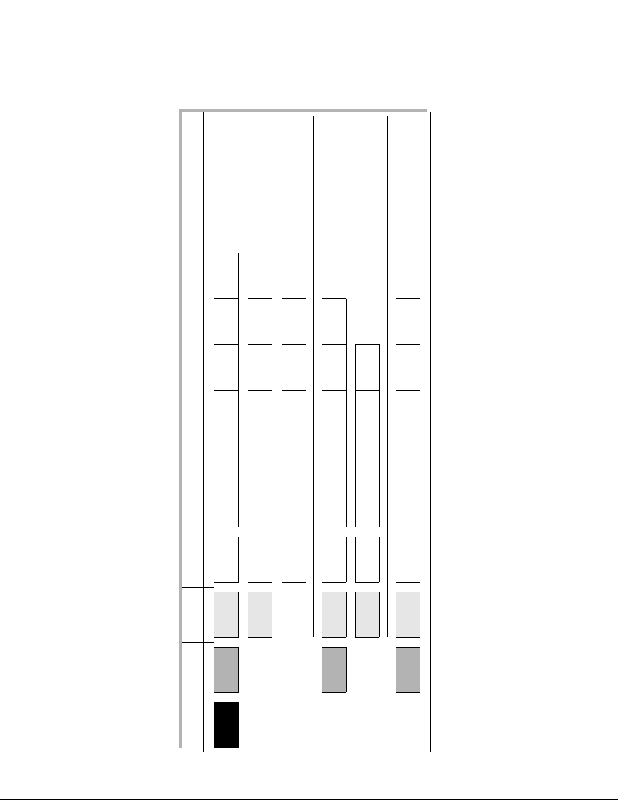
2 Function matrix
2.1 General layout of the function matrix
The function matrix consists of four levels:
Blocks -> Groups -> Function groups -> Functions
0001
0002
A
B
C
D, E, …
AAA
ACA
BAA
CAA
CBA
000
040
200
202
220
042
204
206
0000
0400
0420
2000
2020
2040
2200
2060
0401
0421
2001
2021
2041
2201
0402
0422
2002
2022
2042
2202
0003
0403
0423
2003
2023
2043
2203
0009
…
0409
…
0429
…
2009
…
2029
…
2049
…
…
…
2069
2209
A0000961
20632061 2062
2.1.1 Blocks (A, B, C, etc.)
The blocks are the highest-level grouping of the operation options for the device. The blocks
include, for example: MEASURED VARIABLES, QUICK SETUP, USER INTERFACE, TOTALIZER,
etc.
2.1.2 Groups (AAA, AEA, CAA, etc.)
A block consists of one or more groups. Each group represents a more detailed selection of the
operation options in the higher-order block. The groups in the USER INTERFACE block, for
example, include: CONTROL, MAIN LINE, ADDITIONAL LINE, etc.
2.1.3 Function groups (000, 020, 060, etc.)
A group consists of one or more function groups. Each function group represents a more detailed
selection of the operation options in the higher-order group. The function groups in the CONTROL
group, for example, include: BASIC CONFIGURATION, UN-/LOCKING, OPERATION, etc.
2.1.4 Functions (0000, 0001, 0002, etc.)
Each function group consists of one or more functions. The functions are used to operate and
configure the device. Numerical values can be entered or parameters selected and saved.
The functions in the BASIC CONFIGURATION function group include LANGUAGE, DISPLAY
DAMPING, CONTRAST LCD, etc. The procedure for changing the language of the user interface,
for example, is as follows:
1. Select the block USER INTERFACE.
2. Select the group CONTROL.
3. Select the function group BASIC CONFIGURATION.
4. Select the function LANGUAGE (here you can set the language required).
Page 8 • MN0M023
Issue/Rev. 0.2 (12/12)

Device Functions Proline Promass 83 2 Function matrix
2.1.5 Codes identifying cells
Each cell (block, group, function group and function) in the function matrix has an individual,
unique code.
Blocks:
The code is a letter (A, B, C, etc.)
Groups:
The code consists of three letters (AAA, ABA, BAA, etc.).
The first letter matches the block code (i.e. each group in block A has a code starting with an
A _ _; the codes of the groups in block B start with a B _ _, etc.). The other two letters are for
identifying the group within the respective block.
Function groups:
The code consists of three digits (000, 001, 100, etc.).
Functions:
The code consists of four digits (0000, 0001, 0201, etc.).
The first three digits are the same as the code for the function group.
The last digit in the code is a counter for the functions in the function group, incrementing from
0 to 9 (e.g. function 0005 is the sixth function in group 000).
Block Group
CAAC
Function
group
Functions
2000 2001 2002200
A0001251
Issue/Rev. 0.2 (12/12) MN0M023 • Page 9

2 Function matrix Device Functions Proline Promass 83
2.2 Function matrix Proline Promass 83
BLOCKS GROUPS
MEASURED VARIABLES A
(see p. 11) SYSTEM UNITS ACA
p
QUICK SETUP B
(see p. 25)
MEASURING VALUES AAA
o
SPECIAL-UNITS AEA
Commissioning and application setups
o
p
USER INTERFACE C
(see p. 35) MAIN LINE CCA
p
TOTALIZERS D
(see p. 56) TOTALIZER 2 DAB
p
CONTROL CAA
o
ADDITIONAL LINE CEA
INFORMATION LINE CGA
TOTALIZER 1 DAA
o
TOTALIZER 3 DAC
HANDLING TOTALIZER DJA
Function
o
o
o
o
o
o
o
o
o
o
o
o
groups
see p. 12
see p. 17
see p. 22
see p. 25
see p. 36
see p. 40
see p. 44
see p. 50
see p. 57
see p. 57
see p. 57
see p. 60
OUTPUTS E
(see p. 61) CURRENT OUTPUT 2 EAB
p
INPUTS F
(see p. 111) CURRENT INPUT FCA
CURRENT OUTPUT 1 EAA
o
CURRENT OUTPUT 3 EAC
PULSE/FREQ. OUTPUT 1 ECA
PULSE/FREQ. OUTPUT 2 ECB
RELAY OUTPUT 1 EGA
RELAY OUTPUT 2 EGB
STATUS INPUT FAA
o
p
BASIC FUNCTION G
(see p. 119) PROCESS PARAMETER GIA
p
SPECIAL FUNCTION H
(see p. 139) BATCHING FUNCTION HCA
p
HART GAA
o
SYSTEM PARAMETER GLA
SENSOR DATA GNA
DENSITY FUNCTIONS HAA
o
ADVANCED DIAGNOSIS HEA
o
o
o
o
o
o
o
o
o
o
o
o
o
o
o
o
see p. 62
see p. 62
see p. 62
see p. 74
see p. 74
see p. 101
see p. 101
see p. 112
see p. 115
see p. 120
see p. 122
see p. 133
see p. 135
see p. 141
see p. 147
see p. 166
Page 10 • MN0M023
SUPERVISION J
(see p. 179) VERSION-INFO JCA
SYSTEM JAA
o
see p. 180
o
see p. 185
o
Issue/Rev. 0.2 (12/12)
Device Functions Proline Promass 83 3 Block MEASURED VARIABLES
3 Block MEASURED VARIABLES
(0029) p. 15
CORR. CARR.
VOLUME FLOW
% CARRIER
(0028) p. 15
VOLUME FLOW
PRESSURE
TEMPERATURE
FLOW
(0027) p. 14
CARRER VOL.
FLOW
OTHERS
(0009) p. 12
(0008) p. 12
(0026) p. 14
% CARRIER MASS
FLOW
(0025) p. 14
CARRIER MASS
(0037) p. 16
°BRIX
(0036) p. 16
VOLUME
(0405) p. 19
UNIT CORR.
CONCENT.
FACT. ARB.
(0607) p. 24
TEXT ARB.
(0606) p. 24
CONCENTR.
DENSITY
(0605) p. 23
FACTOR ARB.
Functions
DENSITY
(0006) p. 12
REFERENCE
DENSITY
(0005) p. 12
VOL. FLOW
(0004) p. 12
CORRECTED
(0001) p. 12
VOLUME FLOW
VOL. FLOW
CORR. TARGET
% TARGET
VOLUME FLOW
FLOW
TARGET VOLUME
FLOW
% TARGET MASS
°BALLING
(0024) p. 14
(0023) p. 13
(0022) p. 13
(0021) p. 13
(0035) p. 16
°PLATO
(0034) p. 16
°API
(0033) p. 15
°BAUME
(0031) p. 15
UNIT CORR. VOL.
UNIT VOLUME
UNIT VOLUME
UNIT MASS
FLOW
(0404) p. 19
(0403) p. 18
FLOW
(0402) p. 18
(0401) p. 17
(0426) p. 21
UNIT PRESSURE
(0424) p. 21
UNIT LENGTH
UNIT
(0422) p. 21
TEMPERATURE
DENSITY
(0421) p. 20
UNIT REFERENCE
TEXT ARB.
FACTOR ARB.
TEXT ARB.
FACTOR
DENSITY
(0604) p. 23
VOLUME
(0603) p. 23
VOLUME
(0602) p. 23
ARB. MASS
(0601) p. 22
TEXT
(0420) p. 20
ARB. MASS
(0600) p. 22
(042) p. 20
(060) p. 22
ARBITRARY UNIT
(AEA) p. 22
SPECIAL-UNITS
groups
Function
Groups
MASS FLOW
MAIN VALUES
MEASURING
FLOW
(0000) p. 12
(000) p. 12
VALUES
(AAA) p. 12
(0020) p. 13
TARGET MASS
VALUES
(002) p. 13
ADDITIONAL
(0030) p. 15
% BLACK LIQUOR
UNIT MASS FLOW
(0400) p. 17
UNIT DENSITY
(040) p. 17
CONFIGURATION
ADDITIONAL
CONFIGURATION
(ACA) p. 17
SYSTEM UNITS
Block
(A)
VARIABLES
MEASURED
Issue/Rev. 0.2 (12/12) MN0M023 • Page 11

3 Block MEASURED VARIABLES Device Functions Proline Promass 83
3.1 Group MEASURING VALUES
3.1.1 Function group MAIN VALUES
MEASURED
VARIABLES
A
MEASURING VALUES AAA
MAIN VALUES 000
Function description
MEASURED VARIABLES o MEASURING VALUES o MAIN VALUES
! Note!
• The engineering units of all the measured variables shown here can be set in the “SYSTEM UNITS” group.
• If the fluid in the pipe flows backwards, a negative sign prefixes the flow reading on the display.
MASS FLOW
(0000)
VOLUME FLOW
(0001)
CORRECTED VOLUME
FLOW
(0004)
DENSITY
(0005)
REFERENCE DENSITY
(0006)
The currently measured mass flow appears on the display.
Display:
5-digit floating-point number, including unit and sign
(e.g. 462,87 kg/h; –731.63 lb/min; etc.)
The calculated volume flow appears on the display. The volume flow is derived from the
measured mass flow and the measured density of the fluid.
Display:
5-digit floating-point number, including unit and sign
(e.g. 5.5445 dm
The calculated corrected volume flow appears on the display. The calculated corrected
volume flow is derived from the measured mass flow and the reference density of the
fluid (density at reference temperature, measured or fixed entry).
Display:
5-digit floating-point number, including unit and sign
(e.g. 1.3549 Nm
The currently measured density or its specific gravity appears on the display.
Display:
5-digit floating-point number, incl. unit, corresponds to 0.1000 to 6.0000 kg/dm
(e.g. 1.2345 kg/dm3; 993.5 kg/m3; 1.0015 SG_20 °C; etc.)
The density of the fluid, at reference temperature, appears on the display. The reference
density can be calculated with the measured density or also specified via the function
FIXED REF. DENSITY (6461), (see page 127), or read in directly via the current input.
3
/min; 1.4359 m3/h; –731.63 gal/d; etc.)
3
/h; 7.9846 scm/day; etc.)
3
Page 12 • MN0M023
TEMPERATURE
(0008)
PRESSURE
(0009)
Display:
5-digit floating-point number, incl. unit, corresponds to 0.1000 to 6.0000 kg/dm
(e.g. 1.2345 kg/dm3; 993.5 kg/m3; 1.0015 SG_20 °C; etc.)
The currently measured temperature appears on the display.
Display:
max. 4-digit fixed-point number, including unit and sign
(e.g. –23.4 °C; 160.0 °F; 295.4 K; etc.)
The currently measured pressure appears on the display. This function is not available
unless “pressure” was selected in the ASSIGN CURRENT INPUT function (5200).
Display:
max. 4-digit fixed-point number, including unit and sign
(e.g. 50.0 barg; etc.)
3
Issue/Rev. 0.2 (12/12)

Device Functions Proline Promass 83 3 Block MEASURED VARIABLES
3.1.2 Function group ADDITIONAL VALUES
MEASURED
VARIABLES
MEASURED VARIABLES o MEASURING VALUES o ADDITIONAL VALUES
TARGET MASS FLOW
(0020)
% TARGET MASS FLOW
(0021)
A
MEASURING VALUES AAA
MAIN VALUES 000
ADDITIONAL VALUES 002
Function description
! Note!
This function is not available unless one of the following was selected:
• in the function DENSITY FUNCTION (7000), see page 141:
– % MASS / % VOLUME
– FLEXIBLE and in the function MODE (7010), see page 144, the selection
% MASS 2D or % MASS 3D
Use this function to display the currently measured mass flow of the target fluid. Target
fluid = carried material (e.g. lime powder).
Display:
5-digit floating-point number, including unit and sign
! Note!
This function is not available unless one of the following was selected:
• in the function DENSITY FUNCTION (7000), see page 141:
– % MASS / % VOLUME
– FLEXIBLE and in the function MODE (7010), see page 144, the selection
% MASS 2D or % MASS 3D
TARGET VOLUME FLOW
(0022)
% TARGET VOLUME
FLOW
(0023)
In this function, the currently measured mass flow of the target fluid is displayed as a %
(of the overall mass flow). Target fluid = carried material (e.g. lime powder).
Display:
5-digit floating-point number, including unit and sign
! Note!
This function is not available unless one of the following was selected:
• in the function DENSITY FUNCTION (7000), see page 141:
– % MASS / % VOLUME
– FLEXIBLE and in the function MODE (7010), see page 144, the selection
% VOLUME 2D or % VOLUME 3D
In this function, the currently measured volume flow of the target fluid is displayed.
Target fluid = carried material (e.g. lime powder).
Display:
5-digit floating-point number, including unit and sign
! Note!
This function is not available unless one of the following was selected:
• in the function DENSITY FUNCTION (7000), see page 141:
– % MASS / % VOLUME
– FLEXIBLE and in the function MODE (7010), see page 144, the selection
% VOLUME 2D or % VOLUME 3D
Use this function to display the currently measured volume flow of the target fluid as a %
(of the overall volume flow). Target fluid = carried material (e.g. lime powder).
Display:
5-digit floating-point number, including unit and sign
Issue/Rev. 0.2 (12/12) MN0M023 • Page 13

3 Block MEASURED VARIABLES Device Functions Proline Promass 83
Function description
MEASURED VARIABLES o MEASURING VALUES o ADDITIONAL VALUES
CORRECTED TARGET
VOLUME FLOW
(0024)
! Note!
This function is not available unless % MASS / % VOLUME was selected in the DENSITY
FUNCTION function (7000), (see page 141).
Use this function to display the currently measured corrected volume flow of the target
fluid. Target fluid = carried material (e.g. lime powder).
Display:
5-digit floating-point number, including unit and sign
CARRIER MASS FLOW
(0025)
% CARRIER MASS FLOW
(0026)
CARRIER VOLUME
FLOW
(0027)
! Note!
This function is not available unless one of the following was selected:
• in the function DENSITY FUNCTION (7000), see page 141:
– % MASS / % VOLUME
– FLEXIBLE and in the function MODE (7010), see page 144, the selection
% MASS 2D or % MASS 3D
Use this function to display the currently measured mass flow of the carrier fluid.
Carrier fluid = transporting liquid (e.g. water).
Display:
5-digit floating-point number, including unit and sign
! Note!
This function is not available unless one of the following was selected:
• in the function DENSITY FUNCTION (7000), see page 141:
– % MASS / % VOLUME
– FLEXIBLE and in the function MODE (7010), see page 144, the selection
% MASS 2D or % MASS 3D
Use this function to display the currently measured mass flow of the carrier fluid as a %
(of the overall mass flow). Carrier fluid = transporting liquid (e.g. water).
Display:
5-digit floating-point number, including unit and sign
! Note!
This function is not available unless one of the following was selected:
• in the function DENSITY FUNCTION (7000), see page 141:
– % MASS / % VOLUME
– FLEXIBLE and in the function MODE (7010), see page 144, the selection
% VOLUME 2D or % VOLUME 3D
Page 14 • MN0M023
Use this function to display the currently measured volume flow of the carrier fluid.
Carrier fluid = transporting liquid (e.g. water).
Display:
5-digit floating-point number, including unit and sign
Issue/Rev. 0.2 (12/12)

Device Functions Proline Promass 83 3 Block MEASURED VARIABLES
Function description
MEASURED VARIABLES o MEASURING VALUES o ADDITIONAL VALUES
% CARRIER VOLUME
FLOW
(0028)
! Note!
This function is not available unless one of the following was selected:
• in the function DENSITY FUNCTION (7000), see page 141:
– % MASS / % VOLUME
– FLEXIBLE and in the function MODE (7010), see page 144, the selection %
VOLUME 2D or % VOLUME 3D
Use this function to display the currently measured volume flow of the carrier fluid as a %
(of the overall mass flow). Carrier fluid = transporting liquid (e.g. water).
Display:
5-digit floating-point number, including unit and sign
CORRECTED CARRIER
VOLUME FLOW
(0029)
% BLACK LIQUOR
(0030)
°BAUME
(0031)
! Note!
This function is not available unless % MASS / % VOLUME was selected in the DENSITY
FUNCTION function (7000), (see page 141).
Use this function to display the currently measured corrected volume flow of the carrier
fluid. Carrier fluid = transporting liquid (e.g. water).
Display:
5-digit floating-point number, including unit and sign
! Note!
This function is not available unless %-BLACK LIQUOR was selected in the DENSITY
FUNCTION function (7000), (see page 141).
The concentration in %-BLACK LIQUOR is displayed.
Display:
5-digit floating-point number, incl. units
! Note!
This function is not available unless °BAUME was selected in the DENSITY FUNCTION
function (7000), (see page 141).
The concentration in °BAUME is displayed.
Display:
5-digit floating-point number, incl. units
°API
(0033)
! Note!
This function is not available unless °API was selected in the DENSITY FUNCTION
function (7000), (see page 141).
The concentration in °API is displayed.
Display:
5-digit floating-point number, incl. units
Issue/Rev. 0.2 (12/12) MN0M023 • Page 15

3 Block MEASURED VARIABLES Device Functions Proline Promass 83
Function description
MEASURED VARIABLES o MEASURING VALUES o ADDITIONAL VALUES
°PLATO
(0034)
! Note!
This function is not available unless °PLATO was selected in the DENSITY FUNCTION
function (7000), (see page 141).
The concentration in °PLATO is displayed.
Display:
5-digit floating-point number, incl. units
°BALLING
(0035)
°BRIX
(0036)
OTHERS
(0037)
! Note!
This function is not available unless °BALLING was selected in the DENSITY FUNCTION
function (7000), (see page 141).
The concentration in °BALLING is displayed.
Display:
5-digit floating-point number, incl. units
! Note!
This function is not available unless °BRIX was selected in the DENSITY FUNCTION
function (7000), (see page 141).
The concentration in °BRIX is displayed.
Display:
5-digit floating-point number, incl. units
! Note!
This function is not available unless FLEXIBLE was selected in the DENSITY FUNCTION
function (7000), (see page 141) and this function is not available unless OTHERS 2D or
OTHERS 3D was selected in the MODE function (7010), (see page 144).
Displays the concentration in the unit, which was defined in the function TEXT
ARBITRARY CONCENTRATION (0606), (see page 24).
Display:
5-digit floating-point number, incl. units
Page 16 • MN0M023
Issue/Rev. 0.2 (12/12)

Device Functions Proline Promass 83 3 Block MEASURED VARIABLES
3.2 Group SYSTEM UNITS
3.2.1 Function group CONFIGURATION
MEASURED
VARIABLES
A
MEASURING VALUES AAA
SYSTEM UNITS ACA
Function description
MEASURED VARIABLES o SYSTEM UNITS o CONFIGURATION
You can select the units for measured variables in this function group.
UNIT MASS FLOW
(0400)
Use this function to select the unit for displaying the mass flow (mass/time).
The unit you select here is also valid for:
• Current outputs
• Frequency outputs
• Relay switch points (limit value for mass flow, flow direction)
• Low flow cut off
Options:
Metric:
gram o g/s; g/min; g/h; g/day
kilogram o kg/s; kg/min; kg/h; kg/day
ton o t/s; t/min; t/h; t/day
US:
ounce o oz/s; oz/min; oz/h; oz/day
pound o lb/s; lb/min; lb/h; lb/day
ton o ton/s; ton/min; ton/h; ton/day
For arbitrary units (see function TEXT ARBITRARY MASS on page 22)
_ _ _ _ o _ _ _ _/s; _ _ _ _/min; _ _ _ _/h; _ _ _ _/day
CONFIGURATION 040
Factory setting:
Country-dependent (kg/h or US-lb/min)
! Note!
If you defined a unit of mass in the ARBITRARY UNIT 060 function group (see page 22)
the unit in question is shown here.
UNIT MASS
(0401)
Use this function to select the unit for displaying the mass.
The unit you select here is also valid for:
• Pulse value (e.g. kg/p)
Options:
Metric o g; kg; t
US o oz; lb; ton
For free selectable units o _ _ _ _ (see function TEXT ARBITRARY MASS on page 22)
Factory setting:
Country-dependent (kg or US-lb)
! Note!
• If you defined a unit of mass in the ARBITRARY UNIT 060 function group
(see page 22) the unit in question is shown here.
• The unit of the totalizers is independent of your choice here. The unit for each
totalizer is selected separately for the totalizer in question.
Issue/Rev. 0.2 (12/12) MN0M023 • Page 17

3 Block MEASURED VARIABLES Device Functions Proline Promass 83
Function description
MEASURED VARIABLES o SYSTEM UNITS o CONFIGURATION
UNIT VOLUME FLOW
(0402)
Use this function to select the unit for displaying the volume flow (volume/time).
The unit you select here is also valid for:
• Current outputs
• Frequency outputs
• Relay switch points (limit value for volume flow, flow direction)
• Low flow cut off
Options:
Metric:
Cubic centimeter o cm
Cubic decimeter o dm3/s; dm3/min; dm3/h; dm3/day
Cubic meter o m
Milliliter o ml/s; ml/min; ml/h; ml/day
Liter o l/s; l/min; l/h; l/day
Hectoliter o hl/s; hl/min; hl/h; hl/day
Megaliter o Ml/s; Ml/min; Ml/h; Ml/day
US:
Cubic centimeter o cc/s; cc/min; cc/h; cc/day
Acre foot o af/s; af/min; af/h; af/day
Cubic foot o ft
Fluid ounce o oz f/s; oz f/min; oz f/h; oz f/day
Gallon o gal/s; gal/min; gal/h; gal/day
Kilogallon o Kgal/s; Kgal/min; Kgal/h; Kgal/day
Million gallon o Mgal/s; Mgal/min; Mgal/h; Mgal/day
Barrel (normal fluids: 31.5 gal/bbl) o bbl/s; bbl/min; bbl/h; bbl/day
Barrel (beer: 31.0 gal/bbl) o bbl/s; bbl/min; bbl/h; bbl/day
Barrel (petrochemicals: 42.0 gal/bbl) o bbl/s; bbl/min; bbl/h; bbl/day
Barrel (filling tanks: 55.0 gal/bbl) o bbl/s; bbl/min; bbl/h; bbl/day
3
/s; cm3/min; cm3/h; cm3/day
3
/s; m3/min; m3/h; m3/day
3
/s; ft3/min; ft3/h; ft3/day
UNIT VOLUME
(0403)
Imperial
Gallon o gal/s; gal/min; gal/h; gal/day
Mega gallon o Mgal/s; Mgal/min; Mgal/h; Mgal/day
Barrel (beer: 36.0 gal/bbl) o bbl/s; bbl/min; bbl/h; bbl/day
Barrel (petrochemicals: 34.97 gal/bbl) o bbl/s; bbl/min; bbl/h; bbl/day
For arbitrary units (see function TEXT ARBITRARY VOLUME on page 23)
_ _ _ _ o _ _ _ _/s; _ _ _ _/min; _ _ _ _/h; _ _ _ _/day
Factory setting:
Country-dependent (m
3
/h or US-Mgal/day)
! Note!
If you defined a unit of volume in the ARBITRARY UNIT 060 function group (see
page 22) the unit in question is shown here.
Use this function to select the unit for displaying the volume.
The unit you select here is also valid for: Pulse weighting (e.g. m3/p)
Options:
Metric o cm
US o cc; af; ft3; oz f; gal; Kgal; Mgal; bbl (normal fluids); bbl (beer);
bbl (petrochemicals) o bbl (filling tanks)
Imperial o gal; Mgal; bbl (beer); bbl (petrochemicals)
For free selectable units o _ _ _ _ (see function TEXT ARBITRARY VOLUME on
page 23)
Factory setting:
3
m
3
; dm3; m3; ml; l; hl; Ml Mega
! Note!
• If you defined a unit of volume in the ARBITRARY UNIT 060 function group
(see page 22) the unit in question is shown here.
• The unit of the totalizers is independent of your choice here. The unit for each
totalizer is selected separately for the totalizer in question.
Page 18 • MN0M023
Issue/Rev. 0.2 (12/12)

Device Functions Proline Promass 83 3 Block MEASURED VARIABLES
Function description
MEASURED VARIABLES o SYSTEM UNITS o CONFIGURATION
UNIT CORRECTED
VOLUME FLOW
(0404)
Use this function to select the unit for displaying the corrected volume flow (corrected
volume/time).
The unit you select here is also valid for:
• Current outputs
• Frequency outputs
• Relay switch points (limit value for corrected volume flow, flow direction)
• Low flow cut off
Options:
Metric:
Nl/s
Nl/min
Nl/h
Nl/day
3
Nm
/s
3
Nm
/min
Nm3/h
Nm3/day
US:
Sm3/s;
Sm3/min;
3
Sm
/h;
Sm3/day
Scf/s;
Scf/min;
Scf/h;
Scf/day
UNIT CORRECTED
VOLUME
(0405)
Factory setting:
3
Nm
/h
Use this function to select the unit for displaying the corrected volume.
The unit you select here is also valid for:
• Pulse value (e.g. Nm
3
/p)
Options:
Metric:
3
Nm
Nl
US:
3
Sm
Scf
Factory setting:
3
Nm
! Note!
The unit of the totalizers is independent of your choice here. The unit for each totalizer is
selected separately for the totalizer in question.
Issue/Rev. 0.2 (12/12) MN0M023 • Page 19

3 Block MEASURED VARIABLES Device Functions Proline Promass 83
3.2.2 Function group ADDITIONAL CONFIGURATION
MEASURED
VARIABLES
UNIT DENSITY
(0420)
A
MEASURING VALUES AAA
SYSTEM UNITS ACA
CONFIGURATION 040
ADD. CONFIGURATION 042
Function description
MEASURED VARIABLES o SYSTEM UNITS o ADDITIONAL CONFIGURATION
Use this function to select the unit for displaying the fluid density.
The unit you select here is also valid for:
• Current outputs
• Frequency outputs
• Relay switch points (limit value for density)
• Density response value for EPD
• Density adjustment value
Options:
Metric o g/cm
SG 4 °C, SG 15 °C, SG 20 °C
US o lb/ft
(filling tanks)
Imperial o lb/gal; lb/bbl (beer); lb/bbl (petrochemicals)
Factory setting:
kg/l
3
; g/cc; kg/dm3; kg/l; kg/m3; SD 4 °C, SD 15 °C, SD 20 °C;
3
; lb/gal; lb/bbl (normal fluids); lb/bbl (beer); lb/bbl (petrochemicals); lb/bbl
UNIT REFERENCE
DENSITY
(0421)
SD = Specific Density, SG = Specific Gravity
The specific density is the ratio of fluid density to water density
(at water temperature = 4, 15, 20 °C).
Use this function to select the unit for displaying the reference density.
The unit you select here is also valid for:
• Current outputs
• Frequency outputs
• Relay switch points (limit value for density)
• Fixed reference density (for calculation of corrected volume flow)
• Current input (read in the reference density via current input)
Options:
Metric:
3
kg/Nm
kg/Nl
US:
g/Scc
3
kg/Sm
lb/Scf
Factory setting:
kg/Nl
Page 20 • MN0M023
Issue/Rev. 0.2 (12/12)

Device Functions Proline Promass 83 3 Block MEASURED VARIABLES
Function description
MEASURED VARIABLES o SYSTEM UNITS o ADDITIONAL CONFIGURATION
UNIT TEMPERATURE
(0422)
Use this function to select the unit for displaying the temperature.
The unit you select here is also valid for:
• Current outputs
• Frequency outputs
• Current input
• Relay switch points (limit value for temperature)
• Reference temperature (for corrected volume measurement with measured
reference density)
Options:
°C (Celsius)
K (Kelvin)
°F (Fahrenheit)
°R (Rankine)
Factory setting:
°C
UNIT LENGTH
(0424)
UNIT PRESSURE
(0426)
Use this function to select the unit for displaying the length of the nominal diameter.
The unit you select here is valid for:
• Nominal diameter of sensor (function NOMINAL DIAMETER (6804) on page 135)
Options:
MILLIMETER
INCH
Factory setting:
MILLIMETER
Use this function to select the unit for pressure.
The unit you select here is valid for:
• Specified pressure (see function PRESSURE (6501) on page 132)
Options:
bar a
bar g
psi a
psi g
Factory setting:
bar g
Issue/Rev. 0.2 (12/12) MN0M023 • Page 21

3 Block MEASURED VARIABLES Device Functions Proline Promass 83
3.3 Group SPECIAL-UNITS
3.3.1 Function group ARBITRARY UNIT
MEASURED
VARIABLES
A
MEASURING VALUES AAA
SYSTEM UNITS ACA
SPECIAL-UNITS AEA
ARBITRARY UNIT 060
Function description
MEASURED VARIABLES o SPECIAL-UNITS o ARBITRARY UNIT
Use this function group to define a free selectable unit for mass, mass flow, volume, volume flow, density and
concentration (optional).
TEXT ARBITRARY MASS
(0600)
Use this function to enter a text for the selectable mass unit / mass flow unit. You define
only the text, the unit of time is provided from a choice of options (s, min, h, day).
User input:
xxxxxxx (max. 4 characters)
Valid characters are A-Z, 0-9, +,
Factory setting:
“_ _ _ _” (No text)
Example:
If your text entry is “CENT” (for centner), this text string appears on the display complete
with the unit of time, e.g. “CENT/min”:
CENT = Mass (text input)
CENT / min = Mass flow as shown (on the display)
-, decimal point, white space or underscore
FACTOR ARBITRARY
MASS
(0601)
Use this function to define a quantity factor (without time) for the selectable mass-/
mass flow unit. The mass unit on which this factor is based is one kilogram.
User input:
7-digit floating-point number
Factory setting:
1
Reference quantity:
kg
Example:
One centner is equivalent to 50 kg o0.02 centner = 1 kg
User input: 0.02
Page 22 • MN0M023
Issue/Rev. 0.2 (12/12)

Device Functions Proline Promass 83 3 Block MEASURED VARIABLES
Function description
MEASURED VARIABLES o SPECIAL-UNITS o ARBITRARY UNIT
TEXT ARBITRARY
VOLUME
(0602)
Use this function to enter a text for the selectable volume unit / volume flow unit. You
define only the text, the unit of time is provided from a choice of options (s, min, h, day).
User input:
xxxxxxx (max. 4 characters)
Valid characters are A-Z, 0-9, +,
Factory setting:
“_ _ _ _” (No text)
Example:
If your text entry is “GLAS”, this text string appears on the display complete with the unit
of time, e.g. “GLAS/min”:
GLAS = Volume (text input)
GLAS / min = Volume flow as shown (on the display)
-, decimal point, white space or underscore
FACTOR ARBITRARY
VOLUME
(0603)
TEXT ARBITRARY
DENSITY
(0604)
FACTOR ARBITRARY
DENSITY
(0605)
Use this function to define a quantity factor (without time) for the selectable unit. The
volume unit on which this factor is based is one liter.
User input:
7-digit floating-point number
Factory setting:
1
Reference quantity:
Liter
Example:
The volume of a glass is 0.5 l o2 glasses = 1 liter
User input: 2
Use this function to enter a text for the selectable density unit.
User input:
xxxxxxx (max. 4 characters)
Valid characters are A-Z, 0-9, +,
Factory setting:
“_ _ _ _” (No text)
Example:
Enter text “CE_L” (for centner per liter).
Use this function to define a quantity factor for the selectable density unit. The density
unit on which this factor is based is one kg/l.
User input:
7-digit floating-point number
-, decimal point, white space or underscore
Factory setting:
1
Reference quantity:
kg/l
Example:
One centner per liter is equivalent to 50 kg/l o0.02 centner/l = 1 kg/l
User input: 0.02
Issue/Rev. 0.2 (12/12) MN0M023 • Page 23

3 Block MEASURED VARIABLES Device Functions Proline Promass 83
Function description
MEASURED VARIABLES o SPECIAL-UNITS o ARBITRARY UNIT
TEXT ARBITRARY
CONCENTRATION
(0606)
! Note!
This function is not available unless the optional software package CONCENTRATION is
installed.
Use this function to enter a text for the selectable concentration unit
(user-defined density unit).
User input:
xxxxxxx (max. 4 characters)
Valid characters are A-Z, 0-9, +,
Factory setting:
“_ _ _ _” (No text)
Example:
Enter text “HFCS” (for High Fructose Corn Syrup).
-, decimal point, white space or underscore
FACTOR ARBITRARY
CONCENTRATION
(0607)
! Note!
This function is not available unless the optional software package CONCENTRATION is
installed and an option selected in the function DENSITY FUNCTION (7000),
(see page 141).
Use this function to define a factor for the selectable concentration unit, see function
TEXT ARBITRARY CONCENTRATION (0606).
User input:
7-digit floating-point number
Factory setting:
1
Reference quantity:
Arbitrary concentration unit / %
Example:
The measured concentration 1% should be output as 0.01 HFCS value User input o
0.01 [HFCS]
Page 24 • MN0M023
Issue/Rev. 0.2 (12/12)

Device Functions Proline Promass 83 4 Block QUICK SETUP
4 Block QUICK SETUP
Block Group
QUICK SETUP
(B)
QUICK SETUP
COMMISSIONING
(1002)
QUICK SETUP
PULSATING FLOW
(1003)
Function
groups
QUICK SETUP
COMMISSION
(1002) p. 25
SAVE/LOAD
(1009) p. 26
T-DAT
Functions
QUICK SETUP
PULS.FLOW
(1003) p. 25
QUICK SETUP
GAS MEASUR.
(1004) p. 25
Function description
QUICK SETUP
Use this function to start the Setup menu for commissioning.
Options:
YES
NO
Factory setting:
NO
! Note!
You will find a flowchart of the COMMISSIONING setup menu on page 27. For more
information on Setup menus, please refer to the Operating Instructions
Proline Promass 83, BA 059D/06/en.
Use this function to start the application-specific Setup menu for pulsating flow.
Options:
YES
NO
QUICK SETUP
BATCH/DOSING
(1005) p. 26
QUICK SETUP GAS
MEASUR.
(1004)
Factory setting:
NO
! Note!
You will find a flowchart of the PULSATING FLOW setup menu on page 29. For more
information on Setup menus, please refer to the Operating Instructions
Proline Promass 83, BA 059D/06/en.
Use this function to start the application specific Setup menu for the gas measurement.
Options:
YES
NO
Factory setting:
NO
! Note!
You will find a flowchart of the GAS MEASUREMENT setup menu on page 31. For more
information on Setup menus, please refer to the Operating Instructions
Proline Promass 83, BA 059D/06/en.
Issue/Rev. 0.2 (12/12) MN0M023 • Page 25

4 Block QUICK SETUP Device Functions Proline Promass 83
Function description
QUICK SETUP
QUICK SETUP
BATCHING/DOSING
(1005)
! Note!
This function is only available when the optional software package BATCHING is
installed.
Use this function to start the (optional) application specific Setup menu for batching.
Options:
YES
NO
Factory setting:
NO
! Note!
You will find a flowchart of the BATCHING setup menu on page 32. For more
information on Setup menus, please refer to the Operating Instructions
Proline Promass 83, BA 059D/06/en.
T-DAT SAVE/LOAD
(1009)
Use this function to save the parameter settings / configuration of the transmitter in a
transmitter DAT (T-DAT), or to load the parameter settings from the T-DAT into the
EEPROM (manual safety function).
Application examples:
• After commissioning, the current measuring point parameters can be saved to the
T-DAT as a backup.
• If the transmitter is replaced for some reason, the data from the T-DAT can be loaded
into the new transmitter (EEPROM).
Options:
CANCEL
SAVE (from EEPROM to T-DAT)
LOAD (from the T-DAT into EEPROM)
Factory setting:
CANCEL
! Note!
• If the target device has an older software version, the message “TRANSM. SW–DAT”
is displayed during startup. Then only the “SAVE” function is available.
• LOAD
This function is only possible if the target device has the same software version as, or a
more recent software version than, the source device.
•SAVE
This function is always available.
Page 26 • MN0M023
Issue/Rev. 0.2 (12/12)

Device Functions Proline Promass 83 4 Block QUICK SETUP
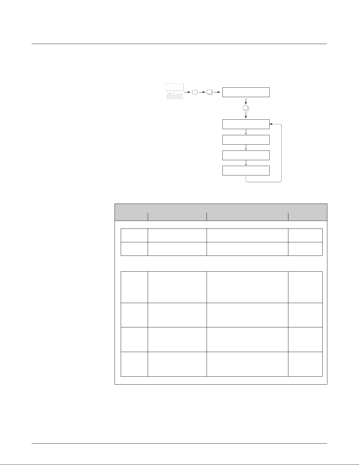
4.1 Setup Commissioning
XXX.XXX.XX
Esc
E
+
-
HOME-POSITION
Mass flow
Unit
Mass flow
Unit
Totalizer
+
Quick Setup
+
E
B
E
+
m
n
Volume flow
Unit
Volume flow
Unit
Totalizer
Corr. Vol. flow
Unit
Corr. Vol. flow
Corr. Vol.
calculation
04040402
646030013001
Density
Reference Calculated
0421 6462
Unit
Ref. Density
Fix. Density
Exp. Coeff. Lin
6461
Exp. Coeff. SQR
Reference temp.
o
Yes
Configure another system unit ?
p
Selection output type
Current output n Freq./Pulse output n
1002
QS
Commission
2000
Language
Pre-setting
Selection pre-settings
Selection system units
Density
04200400
Unit
Density
6463
6464
Operation Mode
4200
Actual SettingsDeliver Settingsy
Temperature
Temperature
Unit
Quit
0422
No
Quit
Current output
Time constant
Yes
Yes
4001
Current span
4002
Value 0/4 mA
4003
Value 20 mA
4004
Meas. mode Meas. mode
4005
4006
q
r
4000
Assign
Automatic parameterization of the display
s
Batching
Pulsating flow
Carrying out the selected Quick Setup
Frequency Pulse
4201
Assign
Freq. output
Value F Low
Value F High
Output signal
Time constantFailsafe mode
Failsafe mode
4203
4204
4205
4206
4207
4208
4209
End value freq.
Configure another output ?
Automatic configuration of display ?
Carrying out another Quick Setup ?
Gas measurement
Assign
Pulse output
Pulse value
Pulse width
Meas. mode
Output signal
Failsafe mode
4221
4222
4223
4225
4226
4227
No
No
No
A0004561-en
Issue/Rev. 0.2 (12/12) MN0M023 • Page 27

4 Block QUICK SETUP Device Functions Proline Promass 83
m Selecting “DELIVERY SETTINGS” returns each selected unit to the factory setting.
Selecting “ACTUAL SETTING” applies the units you have set previously.
n Only units not yet configured in the current Setup are offered for selection in each cycle. The unit for mass,
volume and corrected volume is derived from the corresponding flow unit.
o The “YES” option remains visible until all the units have been configured. “NO” is the only option displayed
when no further units are available.
p Only the outputs not yet configured in the current Setup are offered for selection in each cycle.
q The “YES” option remains visible until all the outputs have been configured. “NO” is the only option displayed
when no further outputs are available.
r The “automatic parameterization of the display” option contains the following basic settings/factory settings:
YES: Main line = Mass flow; Additional line = Totalizer 1; Information line = Operating/system conditions
No: The existing (selected) settings remain.
s The QUICK SETUP BATCHING is only available when the optional software package BATCHING is installed.
!
Note!
• The display returns to the cell QUICK SETUP COMMISSIONING (1002) if you press the X key
combination during parameter interrogation. The stored parameters remain valid.
• The “Commissioning” Quick Setup must be carried out before one of the Quick Setups
explained below is run.
Page 28 • MN0M023
Issue/Rev. 0.2 (12/12)

Device Functions Proline Promass 83 4 Block QUICK SETUP
4.2 Pulsating flow Setup menu
HOME-POSITION
Totalizer
mode (DAA)
XXX.XXX.XX
Esc
-
E
+
+
+
E
m
Totalizer 2Totalizer 1
3002 3002
Yes
Totalizer
mode (DAB)
Configure another totalizer ?
n
Selection of output type
o
Quick Setup
Plusating Flow
Display
damping
Selection totalizer
QS
B
E
+
1003
2002
Totalizer 3
Totalizer
mode (DAC)
Current output n Freq.-/Puse output n
Operation mode
Frequency Pulse
Measuring mode
Time constant
4004
4005
Measuring mode
Time constant
4206
4208
3002
4200
Measuring mode
4225
Quit
No
Quit
Configure another output ?
Yes
p
No
Assign
Quit
8005
6400
6402
6403
6404
Alarm delay
LF-Cut off
On-value
LF-Cut off
Off-value
LF-Cut off
Pressure
shock suppression
Quick Setup
A0002615-en
m Only totalizers not yet configured in the current Setup are offered for selection in each cycle.
n The “YES” option remains visible until all the totalizers have been configured. “NO” is the only option displayed
when no further totalizers are available.
o Only the outputs not yet configured in the current Quick Setup are offered for selection in each cycle.
p The “YES” option remains visible until all the outputs have been configured. “NO” is the only option displayed
when no further outputs are available.
Issue/Rev. 0.2 (12/12) MN0M023 • Page 29

4 Block QUICK SETUP Device Functions Proline Promass 83
!
Note!
• The display returns to the cell QUICK SETUP PULSATING FLOW (1003) if you press the
X key combination during parameter interrogation.
• You can call up this Setup menu either directly from the “COMMISSIONING” Setup menu or
manually by means of the function QUICK SETUP PULSATING FLOW (1003).
Settings for the Pulsating Flow Setup menu:
Fct. code Function name Suggested settings Description
Call up through the function matrix:
B QUICK SETUP QUICK SETUP PULSATING FLOW see p. 25
1003 QUICK SETUP PULS.FLOW YES see p. 25
Basic configuration:
2002 DISPLAY DAMPING 1 second see p. 36
3002 TOTALIZER MODE (DAA) BALANCE see p. 58
3002 TOTALIZER MODE (DAB) BALANCE see p. 58
3002 TOTALIZER MODE (DAC) BALANCE see p. 58
Select the signal type: CURRENT OUTPUT (1...n)
4004 MEASURING MODE PULSATING FLOW see p. 68
4005 TIME CONSTANT 1 second see p. 70
Select the signal type: FREQ./PULSE OUTPUT (1...2) / operating mode: FREQUENCY
4206 MEASURING MODE PULSATING FLOW see p. 79
4208 TIME CONSTANT 0 seconds see p. 84
Select the signal type: FREQ./PULSE OUTPUT (1...2) / operating mode: PULSE
4225 MEASURING MODE PULSATING FLOW see p. 87
Other settings:
8005 ALARM DELAY 0 seconds see p. 181
6400 ASSIGN LF CUT OFF MASS FLOW see p. 122
6402 ON-VALUE LOW FLOW CUT
OFF
6403 OFF-VALUE LOW FLOW CUT
OFF
6404 PRESSURE SHOCK
SUPPRESSION
Depends on diameter (DN [mm]):
– DN 1 = 0.02 [kg/h] or [l/h]
– DN 2 = 0.10 [kg/h] or [l/h]
– DN 4 = 0.45 [kg/h] or [l/h]
– DN 8 = 2.0 [kg/h] or [l/h]
– DN 15 = 6.5 [kg/h] or [l/h]
– DN 15* = 18 [kg/h] or [l/h]
– DN 25 = 18 [kg/h] or [l/h]
– DN 25* = 45 [kg/h] or [l/h]
– DN 40 = 45 [kg/h] or [l/h]
– DN 40* = 70 [kg/h] or [l/h]
– DN 50 = 70 [kg/h] or [l/h]
– DN 50* = 180 [kg/h] or [l/h]
– DN 80 = 180 [kg/h] or [l/h]
– DN 100 = 350 [kg/h] or [l/h]
– DN 150 = 650 [kg/h] or [l/h]
– DN 250 = 1800 [kg/h] or [l/h]
*DN 15, 25, 40 “FB” = Full bore
versions Promass I
50% see p. 122
0 s see p. 123
see p. 122
Page 30 • MN0M023
Issue/Rev. 0.2 (12/12)
Device Functions Proline Promass 83 4 Block QUICK SETUP
4.3 Gas measurement Setup menu
XXX.XXX.XX
Esc
E
+
-
HOME-POSITION
+
+
E
Quick SetupQuick Setup
E
+
QS
Gas measurement
Assign
Low flow cut off
On-value
Low flow cut off
Off-value
Low flow cut off
B
1004
6400
6402
6403
Settings for the Gas Measurement Setup menu:
Fct. code Function name Suggested settings Description
Call up through the function matrix:
B QUICK SETUP QUICK SETUP GAS MEASUR. see p. 25
1004 QUICK SETUP GAS MEASUR. YES see p. 25
A0002502-en
Basic configuration:
6420 EMPTY PIPE DETECTION No entry possible, the selection changes
automatically to OFF.
6400 ASSIGN LOW FLOW CUT OFF For gas measurement we recommend
to switch off the low flow cut off.
OFF
6402 ON-VALUE LOW FLOW CUT
OFF
6403 OFF-VALUE LOW FLOW CUT
OFF
If you don’t switch off the low flow cut off:
0.0000
If you don’t switch off the low flow cut off:
50%
see p. 125
see p. 122
see p. 122
see p. 122
Issue/Rev. 0.2 (12/12) MN0M023 • Page 31

4 Block QUICK SETUP Device Functions Proline Promass 83
4.4 Batching Setup menu
This Setup menu guides the user systematically through all the device functions that have to be
adjusted and configured for batching operation.
The Setup menu settings result in a (simple) one-stage batching process. The parameters for
additional settings, e.g. for automatic compensation of after-runs or multistage batching must be
manually set in the function matrix.
XXX.XXX.XX
Esc
E
+
-
HOME-POSITION
+
E
Relay 1 Relay 2
Quick Setup
QS
Batching/Dosing
ON-Value
Low flow cut off
Flow
damping
Pressure shock
suppression
Batch
Selector
Batch
Name
Batch
Quantity
Fix
Compensation Quantity
Select
Output?
B
E
+
1005
6402
6603
6404
7200
7201
7203
7204
!
Assign
Relay
Terminal No.
YES NO
Max. Batch
Time
7240
YES NO
Locked Access Customer
PRESET
Batch quantity
Automatic parameterization
of the display
Batch
Supervision?
Autom. Configuration
Display?
4700
4780
Quit Quick Setup
A0004644-en
Note!
• This Setup menu is only available when the optional software package BATCHING is installed in
the measuring device. By means of the order option, the software package can already be
installed in the measuring device when delivered from the factory or it can be ordered at a later
date from Endress + Hauser and installed as an optional software package.
Page 32 • MN0M023
Issue/Rev. 0.2 (12/12)

Device Functions Proline Promass 83 4 Block QUICK SETUP
• The display returns to the function QUICK SETUP BATCHING/DOSING (1005), if you press
the ESC key combination during parameter interrogation.
• At the start of the Setup, general device parameters are optimally configured for measuring signal
processing and output response.
• Then you can enter the specific batching parameters, starting with the options list “Batching
1...6”. In this way, by running through the Setup menu a number of times, up to six different
batching parameter sets (incl. special naming) can be created and called up as necessary.
• In order to enjoy full functionality, it is advisable to let the display parameters be set
automatically. This means that the lowest display line is configured as the batching menu.
Softkeys are displayed which can be used to start or stop the batching process in the HOME
position. In this way, the measuring device can be fully deployed as a “batch controller”.
Caution!
"
By running the Setup, certain device parameters are optimally set for discontinuous operation.
Should the measuring device be used for continuous flow measurement at a later time, we
recommend you to rerun the “COMMISSIONING” or the “PULSATING FLOW” Setup.
Settings for the Batching Setup menu:
Fct. code Function name Suggested settings Description
Call up through the function matrix:
B QUICK SETUP QUICK SETUP
BATCHING/DOSING
1005 QUICK SETUP BATCHING/DOSING YES see p. 26
see p. 25
Settings (functions with a gray background are set automatically):
6400 ASSIGN LOW FLOW CUT OFF Mass see p. 122
6402 ON-VALUE LOW FLOW CUT OFF Table value see p. 122
6403 OFF-VALUE LOW FLOW CUT OFF 50% see p. 122
6603 FLOW DAMPING 0 seconds see p. 133
6404 PRESSURE SHOCK SUPPRESSION 0 seconds see p. 123
7200 BATCH SELECTOR BATCH #1 see p. 147
7202 BATCH NAME BATCH #1 see p. 147
7201 ASSIGN BATCH VARIABLE Mass see p. 148
7203 BATCH QUANTITY 0 see p. 148
7204 FIX COMPENSATION QUANTITY 0 see p. 149
7205 COMPENSATION MODE OFF see p. 149
7208 BATCH STAGES 1 see p. 152
7209 INPUT FORMAT Value input see p. 152
4700 ASSIGN RELAY BATCHING VALVE 1 see p. 101
4780 TERMINAL NUMBER Output (display only) see p. 107
7220 OPEN VALVE 1 0% or 0 [unit] see p. 153
7240 MAXIMUM BATCHING TIME 0 seconds (Off) see p. 158
7241 MIN. BATCHING QUANTITY 0 seconds see p. 159
7242 MAX. BATCHING QUANTITY 0 seconds see p. 160
2200 ASSIGN (Main line) BATCH NAME see p. 40
2220 ASSIGN (Multiplex main line) Off see p. 42
2400 ASSIGN (Additional line) BATCH DOWNWARDS see p. 44
2420 ASSIGN (Multiplex additional line) Off see p. 47
2600 ASSIGN (Info line) BATCHING KEYS see p. 50
2620 ASSIGN (Multiplex info line) Off see p. 53
Issue/Rev. 0.2 (12/12) MN0M023 • Page 33

4 Block QUICK SETUP Device Functions Proline Promass 83
N
4.5 Data back-up/transfer
You can use the T-DAT SAVE/LOAD function to transfer data (device parameters and settings)
between the T-DAT (removable memory) and the EEPROM (device memory).
This is required for the following applications:
• Creating a backup: current data are transmitted from an EEPROM to the T-DAT.
• Replacing a transmitter: current data are copied from an EEPROM to the T-DAT, then transmitted
to the EEPROM of the new transmitter.
• Duplicating data: current data are copied from an EEPROM to the T-DAT, then transmitted to
EEPROMs of identical measuring points.
!
Note!
Installing and removing the T-DAT oOperating Instructions of the Promass 83 (BA059D)
XXX.XXX.XX
HOME
POSITION
Esc
-
+
LOAD
F
E
O
P
F
P
NO
F
YES
F
Restart of the
measuring device
Data storage/transmission with T-DAT SAVE/LOAD
YES
F
Input is
saved
Quick Setup
T-DAT
SAVE/LOAD
F
P
NO
F
P
CANCELSAVE
Notes on the LOAD and SAVE options:
LOAD:
Data are transmitted from the T-DAT to the EEPROM.
a0001221-en
Page 34 • MN0M023
!
Note!
• Previously saved settings on the EEPROM are deleted.
• This selection is available only if the T-DAT contains valid data.
• This selection can be made only if the software version of the T-DAT is the same or newer than
that of the EEPROM. Otherwise, the error message "TRANSM. SW-DAT" appears after the restart
and the LOAD function is subsequently no longer available.
SAVE:
Data are transmitted from the EEPROM to the T-DAT.
Issue/Rev. 0.2 (12/12)

Device Functions Proline Promass 83 5 Block USER INTERFACE
5 Block USER INTERFACE
Functions
groups
Function
Groups
(2004) p. 35
BACKLIGHT
(2003) p. 37
CONTRAST LCD
DISPLAY
DAMPING
(2002) p. 36
(2000) p. 36
LANGUAGE
(200) p. 36
BASIC CONFIG.
CONTROL
(CAA) p. 36
CNTR
(2023) p. 38
ACCESS CODE
(2022) p. 38
STATUS ACCESS
CODE
(2021) p. 38
DEF.PRIVATE
(2020) p. 38
ACCESS CODE
(202) p. 38
UN-/LOCKING
(2403) p. 46
DISPLAY MODE
FORMAT
100% VALUE
ASSIGN
(2040) p. 39
TEST DISPLAY
(204) p. 39
OPERATION
CONFIGURATION
MAIN LINE
FORMAT
(2202) p. 41
(2201) p. 41
100% VALUE
ASSIGN
(2200) p. 40
(220) p. 40
MULTIPLEX
(CCA) p. 40
FORMAT
(2222) p. 43
(2221) p. 43
100% VALUE
(2402) p. 46
(2401) p. 45
ASSIGN
(2220) p. 42
(2400) p. 44
(222) p. 42
(240) p. 44
CONFIGURATION
LINE
(CEA) p. 44
ADDITIONAL
(2423) p. 49
DISPLAY MODE
FORMAT
(2422) p. 49
(2421) p. 48
100% VALUE
ASSIGN
(2420) p. 47
(242) p. 47
MULTIPLEX
DISPLAY MODE
FORMAT
100% VALUE
ASSIGN
CONFIGURATION
(2603) p. 52
(2602) p. 52
(2601) p. 51
(2600) p. 50
(260) p. 50
(2623) p. 55
DISPLAY MODE
FORMAT
(2622) p. 55
(2621) p. 54
100% VALUE
ASSIGN
(2620) p. 53
(262) p. 53
MULTIPLEX
LINE
(CGA) p. 50
INFORMATION
Block
INTERFACE
(C)
USER
Issue/Rev. 0.2 (12/12) MN0M023 • Page 35

5 Block USER INTERFACE Device Functions Proline Promass 83
5.1 Group CONTROL
5.1.1 Function group BASIC CONFIGURATION
USER INTERFACE C
LANGUAGE
(2000)
CONTROL CAA
BASIC CONFIGURATION 200
Function description
USER INTERFACE o CONTROL o BASIC CONFIGURATION
Use this function to select the language for all texts, parameters and messages shown on
the local display.
! Note!
The displayed options depend on the available language group shown in the LANGUAGE
GROUP (8226) function.
Options:
Language group WEST EU / USA:
ENGLISH
DEUTSCH
FRANCAIS
ESPANOL
ITALIANO
NEDERLANDS
PORTUGUESE
Language group EAST EU / SCAND:
ENGLISH
NORSK
SVENSKA
SUOMI
POLISH
RUSSIAN
CZECH
DISPLAY DAMPING
(2002)
Language group ASIA:
ENGLISH
BAHASA INDONESIA
JAPANESE (syllabary)
Language group CHINA:
ENGLISH
CHINESE
Factory setting:
Country-dependent (page 190)
! Note!
• If you press the O/S keys at startup, the language defaults to “ENGLISH”.
• You can change the language group via the configuration software FieldCare. Please do
not hesitate to contact your E+H sales office if you have any questions.
Use this function to enter a time constant defining how the display reacts to severely
fluctuating flow variables, either very quickly (enter a low time constant) or with
damping (enter a high time constant).
User input:
0...100 seconds
Factory setting:
1 s
! Note!
Setting the time constant to zero seconds switches off damping.
Page 36 • MN0M023
Issue/Rev. 0.2 (12/12)

Device Functions Proline Promass 83 5 Block USER INTERFACE
Function description
USER INTERFACE o CONTROL o BASIC CONFIGURATION
CONTRAST LCD
(2003)
BACKLIGHT
(2004)
Use this function to optimize display contrast to suit local operating conditions.
User input:
10...100%
Factory setting:
50%
Use this function to optimize the backlight to suit local operating conditions.
User input:
0...100%
! Note!
Entering the value “0” means that the backlight is “switched off”. The display then no
longer emits any light, i.e. the display texts can no longer be read in the dark.
Factory setting:
50%
Issue/Rev. 0.2 (12/12) MN0M023 • Page 37

5 Block USER INTERFACE Device Functions Proline Promass 83
5.1.2 Function group UNLOCKING/ LOCKING
USER INTERFACE C
ACCESS CODE
(2020)
DEFINE PRIVATE CODE
(2021)
CONTROL CAA
BASIC CONFIGURATION 200
UNLOCKING/ LOCKING 202
Function description
USER INTERFACE o CONTROL o UNLOCKING/ LOCKING
All data of the measuring system are protected against inadvertent change. Programming
is disabled and the settings cannot be changed until a code is entered in this function. If
you press the O/S keys in any function, the measuring system automatically goes to this
function and the prompt to enter the code appears on the display (when programming is
disabled).
You can enable programming by entering your personal code (Factory setting = 83,
see function DEFINE PRIVATE CODE (2021)).
User input:
max. 4-digit number: 0 ...9999
! Note!
• Programming is disabled if you do not press a key within 60 seconds following
automatic return to the HOME position.
• You can also disable programming in this function by entering any number (other than
the defined private code).
• The Endress+Hauser service organization can be of assistance if you mislay your
personal code.
Use this function to specify a personal code for enabling programming in the function
ACCESS CODE.
STATUS ACCESS
(2022)
ACCESS CODE
COUNTER
(2023)
User input:
0...9999 (max. 4-digit number)
Factory setting:
83
! Note!
• Programming is always enabled with the code “0”.
• Programming has to be enabled before this code can be changed. When programming
is disabled this function is not available, thus preventing others from accessing your
personal code.
Use this function to check the access status for the function matrix.
Display:
ACCESS CUSTOMER (parameterization possible)
LOCKED (parameterization disabled)
Displays how often the customer code, service code or the digit “0” (code-free) has been
entered to gain access to the function matrix.
Display:
max. 7-digit number: 0...9999999
Factory setting:
0
Page 38 • MN0M023
Issue/Rev. 0.2 (12/12)

Device Functions Proline Promass 83 5 Block USER INTERFACE
5.1.3 Function group OPERATION
USER INTERFACE C
TEST DISPLAY
(2040)
CONTROL CAA
BASIC CONFIGURATION 200
UNLOCKING/ LOCKING 202
OPERATION 204
Function description
USER INTERFACE o CONTROL o OPERATION
Use this function to test the operability of the local display and its pixels.
Options:
OFF
ON
Factory setting:
OFF
Test sequence:
1. Start the test by selecting ON.
2. All pixels of the main line, additional line and information line are darkened for
minimum 0.75 second.
3. Main line, additional line and information line show an “8” in each field for
minimum 0.75 seconds.
4. Main line, additional line and information line show a “0” in each field for minimum
0.75 seconds.
5. Main line, additional line and information line show nothing (blank display) for
minimum 0.75 second.
When the test is completed, the local display returns to its initial state and the setting
changes to OFF.
Issue/Rev. 0.2 (12/12) MN0M023 • Page 39

5 Block USER INTERFACE Device Functions Proline Promass 83
5.2 Group MAIN LINE
5.2.1 Function group CONFIGURATION
USER INTERFACE C
ASSIGN
(2200)
CONTROL CAA
MAIN LINE CCA
CONFIGURATION 220
Function description
USER INTERFACE o MAIN LINE o CONFIGURATION
1
2
Esc
+
-
1 = main line, 2 = additional line, 3 = information line
In this function, a value to be displayed is assigned to the main line (top line in the local
display). This value is displayed during normal operation.
Options (standard):
OFF
MASS FLOW
MASS FLOW IN %
VOLUME FLOW
VOLUME FLOW IN %
CORRECTED VOLUME FLOW
CORRECTED VOLUME FLOW IN %
DENSITY
REFERENCE DENSITY
TEMPERATURE
ACTUAL CURRENT (1...3)
ACTUAL FREQUENCY (1...2)
TOTALIZER (1...3)
ACTUAL CURRENT INPUT
3
E
A0001253
Page 40 • MN0M023
Factory setting:
MASS FLOW
Advanced options with optional software package BATCHING:
BATCH NAME (“BATCH # 1” or “BEER 330”, etc.)
BATCH QUANTITY (overall quantity to be batched)
BATCH COUNTER (batching processes carried out)
BATCH SUM (effective total batching quantity)
! Note!
The options given in the BATCHING software package always refer to the batching
selected (“BATCH # 1”, “BATCH # 2”, etc.) in the BATCH SELECTOR function
(page 147). Example: If BATCH # 1 was selected in the BATCH SELECTOR function
(7200), then only the values from BATCH # 1 (batch name, batch quantity etc.) can be
displayed.
(continued on next page)
Issue/Rev. 0.2 (12/12)

Device Functions Proline Promass 83 5 Block USER INTERFACE
Function description
USER INTERFACE o MAIN LINE o CONFIGURATION
ASSIGN
(continued)
Advanced options with optional software package CONCENTRATION:
TARGET MASS FLOW
% TARGET MASS FLOW
TARGET VOLUME FLOW
% TARGET VOLUME FLOW
CORRECTED TARGET VOLUME FLOW
CARRIER MASS FLOW
% CARRIER MASS FLOW
CARRIER VOLUME FLOW
% CARRIER VOLUME FLOW
CORRECTED CARRIER VOLUME FLOW
% BLACK LIQUOR
°BAUME
°API
°PLATO
°BALLING
°BRIX
OTHERS (_ _ _ _ flexible concentration)
Advanced options with optional software package ADVANCED DIAGNOSIS:
MASS FLOW DEVIATION
DENSITY DEVIATION
REFERENCE DENSITY DEVIATION
TEMPERATURE DEVIATION
TUBE DAMPING DEVIATION
ELECTRODYNAMIC SENSOR DEVIATION
OPERATING FREQUENCY FLUCTUATION DEVIATION
TUBE DAMPING FLUCTUATION DEVIATION
100% VALUE
(2201)
FORMAT
(2202)
! Note!
This function is not available unless one of the following was selected in the ASSIGN
function (2200):
• MASS FLOW IN %
• VOLUME FLOW IN %
• CORRECTED VOLUME FLOW IN %
Use this function to define the flow value to be shown on the display as the 100% value.
User input:
5-digit floating-point number
Factory setting:
10 kg/s, 10 l/s or 10 Nl/s
Use this function to define the maximum number of places after the decimal point
displayed for the reading in the main line.
Options:
XXXXX. - XXXX.X - XXX.XX - XX.XXX -X.XXXX
Factory setting:
X.XXXX
! Note!
• Note that this setting only affects the reading as it appears on the display, it has no
influence on the accuracy of the system's calculations.
• The places after the decimal point as computed by the measuring device cannot always
be displayed, depending on this setting and the engineering unit. In such instances an
arrow appears on the display between the measuring value and the engineering unit
(e.g. 1.2 okg/h), indicating that the measuring system is computing with more
decimal places than can be shown on the display.
Issue/Rev. 0.2 (12/12) MN0M023 • Page 41

5 Block USER INTERFACE Device Functions Proline Promass 83
5.2.2 Function group MULTIPLEX
USER INTERFACE C
ASSIGN
(2220)
CONTROL CAA
MAIN LINE CCA
CONFIGURATION 220
MULTIPLEX 222
Function description
USER INTERFACE o MAIN LINE o MULTIPLEX
Use this function to define the second reading to be displayed in the main line alternately
(every 10 seconds) with the value defined in the ASSIGN function (2200).
Options (standard):
OFF
MASS FLOW
MASS FLOW IN %
VOLUME FLOW
VOLUME FLOW IN %
CORRECTED VOLUME FLOW
CORRECTED VOLUME FLOW IN %
DENSITY
REFERENCE DENSITY
TEMPERATURE
ACTUAL CURRENT (1...3)
ACTUAL FREQUENCY (1...2)
TOTALIZER (1...3)
ACTUAL CURRENT INPUT
Factory setting:
OFF
Advanced options with optional software package BATCHING:
BATCH NAME (“BATCH # 1” or “BEER 330”, etc.)
BATCH QUANTITY (overall quantity to be batched)
BATCH COUNTER (batching processes carried out)
BATCH SUM (effective total batching quantity)
! Note!
The options given in the BATCHING software package always refer to the batching
selected (“BATCH # 1”, “BATCH # 2”, etc.) in the BATCH SELECTOR function
(page 147). Example: If BATCH # 1 was selected in the BATCH SELECTOR function
(7200), then only the values from BATCH # 1 (batch name, batch quantity etc.) can be
displayed.
Advanced options with optional software package CONCENTRATION:
TARGET MASS FLOW
% TARGET MASS FLOW
TARGET VOLUME FLOW
% TARGET VOLUME FLOW
CORRECTED TARGET VOLUME FLOW
CARRIER MASS FLOW
% CARRIER MASS FLOW
CARRIER VOLUME FLOW
% CARRIER VOLUME FLOW
CORRECTED CARRIER VOLUME FLOW
% BLACK LIQUOR
°BAUME
°API
°PLATO
°BALLING
°BRIX
OTHERS (_ _ _ _ flexible concentration)
Page 42 • MN0M023
(continued on next page)
Issue/Rev. 0.2 (12/12)

Device Functions Proline Promass 83 5 Block USER INTERFACE
Function description
USER INTERFACE o MAIN LINE o MULTIPLEX
ASSIGN
(continued)
Advanced options with optional software package ADVANCED DIAGNOSIS:
MASS FLOW DEVIATION
DENSITY DEVIATION
REFERENCE DENSITY DEVIATION
TEMPERATURE DEVIATION
TUBE DAMPING DEVIATION
ELECTRODYNAMIC SENSOR DEVIATION
OPERATING FREQUENCY FLUCTUATION DEVIATION
TUBE DAMPING FLUCTUATION DEVIATION
100% VALUE
(2221)
FORMAT
(2222)
! Note!
This function is not available unless one of the following was selected in the ASSIGN
function (2220):
• MASS FLOW IN %
• VOLUME FLOW IN %
• CORRECTED VOLUME FLOW IN %
Use this function to define the flow value to be shown on the display as the 100% value.
User input:
5-digit floating-point number
Factory setting:
10 kg/s, 10 l/s or 10 Nl/s
Use this function to define the maximum number of places after the decimal point for the
second value displayed in the main line.
Options:
XXXXX. - XXXX.X - XXX.XX - XX.XXX -X.XXXX
Factory setting:
X.XXXX
! Note!
• Note that this setting only affects the reading as it appears on the display, it has no
influence on the accuracy of the system's calculations.
• The places after the decimal point as computed by the measuring device cannot always
be displayed, depending on this setting and the engineering unit. In such instances an
arrow appears on the display between the measuring value and the engineering unit
(e.g. 1.2 okg/h), indicating that the measuring system is computing with more
decimal places than can be shown on the display.
Issue/Rev. 0.2 (12/12) MN0M023 • Page 43

5 Block USER INTERFACE Device Functions Proline Promass 83
5.3 Group ADDITIONAL LINE
5.3.1 Function group CONFIGURATION
USER INTERFACE C
ASSIGN
(2400)
CONTROL CAA
MAIN LINE CCA
ADDITIONAL LINE CEA
CONFIGURATION 240
Function description
USER INTERFACE o ADDITIONAL LINE o CONFIGURATION
1
2
Esc
+
-
1 = main line, 2 = additional line, 3 = information line
In this function, a value to be displayed is assigned to the additional line (middle line in
the local display). This value is displayed during normal operation.
Options (standard):
OFF
MASS FLOW
MASS FLOW IN %
VOLUME FLOW
VOLUME FLOW IN %
CORRECTED VOLUME FLOW
CORRECTED VOLUME FLOW IN %
DENSITY
REFERENCE DENSITY
TEMPERATURE
MASS FLOW BARGRAPH IN %
VOLUME FLOW BARGRAPH IN %
CORRECTED VOLUME FLOW BARGRAPH IN %
ACTUAL CURRENT (1...3)
ACTUAL FREQUENCY (1...2)
TOTALIZER (1...3)
TAG NAME
ACTUAL CURRENT INPUT
3
E
A0001253
Page 44 • MN0M023
Factory setting:
TOTALIZER 1
Advanced options with optional software package BATCHING:
BATCH NAME (“BATCH # 1” or “BEER 330”, etc.)
BATCH QUANTITY (overall quantity to be batched)
BATCH COUNTER (batching processes carried out)
BATCH SUM (effective total batching quantity)
BATCH UPWARDS (batching progress upwards)
BATCH DOWNWARDS (batching progress downwards)
(continued on next page)
Issue/Rev. 0.2 (12/12)

Device Functions Proline Promass 83 5 Block USER INTERFACE
Function description
USER INTERFACE o ADDITIONAL LINE o CONFIGURATION
ASSIGN
(continued)
! Note!
The options given in the BATCHING software package always refer to the batching
selected (“BATCH # 1”, “BATCH # 2”, etc.) in the BATCH SELECTOR function
(page 147). Example: If BATCH # 1 was selected in the BATCH SELECTOR function
(7200), then only the values from BATCH # 1 (batch name, batch quantity etc.) can be
displayed.
Advanced options with optional software package CONCENTRATION:
TARGET MASS FLOW
% TARGET MASS FLOW
TARGET VOLUME FLOW
% TARGET VOLUME FLOW
CORRECTED TARGET VOLUME FLOW
CARRIER MASS FLOW
% CARRIER MASS FLOW
CARRIER VOLUME FLOW
% CARRIER VOLUME FLOW
CORRECTED CARRIER VOLUME FLOW
% BLACK LIQUOR
° BAUME
° API
° PLATO
° BALLING
° BRIX
OTHERS (_ _ _ _ flexible concentration)
100% VALUE
(2401)
Advanced options with optional software package ADVANCED DIAGNOSIS:
MASS FLOW DEVIATION
DENSITY DEVIATION
REFERENCE DENSITY DEVIATION
TEMPERATURE DEVIATION
TUBE DAMPING DEVIATION
ELECTRODYNAMIC SENSOR DEVIATION
OPERATING FREQUENCY FLUCTUATION DEVIATION
TUBE DAMPING FLUCTUATION DEVIATION
! Note!
This function is not available unless one of the following was selected in the ASSIGN
function (2400):
• MASS FLOW IN %
• VOLUME FLOW IN %
• CORRECTED VOLUME FLOW IN %
• MASS FLOW BARGRAPH IN %
• VOLUME FLOW BARGRAPH IN %
• CORRECTED VOLUME FLOW BARGRAPH IN %
Use this function to define the flow value to be shown on the display as the 100% value.
User input:
5-digit floating-point number
Factory setting:
10 kg/s, 10 l/s or 10 Nl/s
Issue/Rev. 0.2 (12/12) MN0M023 • Page 45

5 Block USER INTERFACE Device Functions Proline Promass 83
Function description
USER INTERFACE o ADDITIONAL LINE o CONFIGURATION
FORMAT
(2402)
! Note!
This function is not available unless a number was selected in the ASSIGN function
(2400).
Use this function to define the maximum number of places after the decimal point
displayed for the reading in the additional line.
Options:
XXXXX. - XXXX.X - XXX.XX - XX.XXX -X.XXXX
Factory setting:
X.XXXX
! Note!
• Note that this setting only affects the reading as it appears on the display, it has no
influence on the accuracy of the system's calculations.
• The places after the decimal point as computed by the measuring device cannot always
be displayed, depending on this setting and the engineering unit. In such instances an
arrow appears on the display between the measuring value and the engineering unit
(e.g. 1.2 okg/h), indicating that the measuring system is computing with more
decimal places than can be shown on the display.
DISPLAY MODE
(2403)
! Note!
This function is not available unless one of the following was selected in the ASSIGN
function (2400):
• MASS FLOW BARGRAPH IN %
• VOLUME FLOW BARGRAPH IN %
• CORRECTED VOLUME FLOW BARGRAPH IN %
Use this function to define the format of the bar graph.
Options:
STANDARD
Simple bar graph with 25 / 50 / 75% gradations and integrated sign.
A0001258
SYMMETRY
Symmetrical bar graph for positive and negative directions of flow, with
–50 / 0 / +50% gradations and integrated sign..
A0001259
Factory setting:
STANDARD
Page 46 • MN0M023
Issue/Rev. 0.2 (12/12)

Device Functions Proline Promass 83 5 Block USER INTERFACE
5.3.2 Function group MULTIPLEX
USER INTERFACE C
ASSIGN
(2420)
CONTROL CAA
MAIN LINE CCA
ADDITIONAL LINE CEA
CONFIGURATION 240
MULTIPLEX 242
Function description
USER INTERFACE o ADDITIONAL LINE o MULTIPLEX
Use this function to define the second reading to be displayed in the additional line
alternately (every 10 seconds) with the value defined in the function ASSIGN (2400).
Options (standard):
OFF
MASS FLOW
MASS FLOW IN %
VOLUME FLOW
VOLUME FLOW IN %
CORRECTED VOLUME FLOW
CORRECTED VOLUME FLOW IN %
DENSITY
REFERENCE DENSITY
TEMPERATURE
MASS FLOW BARGRAPH IN %
VOLUME FLOW BARGRAPH IN %
CORRECTED VOLUME FLOW BARGRAPH IN %
ACTUAL CURRENT (1...3)
ACTUAL FREQUENCY (1...2)
TOTALIZER (1...3)
TAG NAME
ACTUAL CURRENT INPUT
Factory setting:
OFF
Advanced options with optional software package BATCHING:
BATCH NAME (“BATCH # 1” or “BEER 330”, etc.)
BATCH QUANTITY (overall quantity to be batched)
BATCH COUNTER (batching processes carried out)
BATCH SUM (effective total batching quantity)
BATCH UPWARDS (batching progress upwards)
BATCH DOWNWARDS (batching progress downwards)
! Note!
The options given in the BATCHING software package always refer to the batching
selected (“BATCH # 1”, “BATCH # 2”, etc.) in the BATCH SELECTOR function
(page 147). Example: If BATCH # 1 was selected in the BATCH SELECTOR function
(7200), then only the values from BATCH # 1 (batch name, batch quantity etc.) can be
displayed.
(continued on next page)
Issue/Rev. 0.2 (12/12) MN0M023 • Page 47

5 Block USER INTERFACE Device Functions Proline Promass 83
Function description
USER INTERFACE o ADDITIONAL LINE o MULTIPLEX
ASSIGN
(continued)
Advanced options with optional software package CONCENTRATION:
TARGET MASS FLOW
% TARGET MASS FLOW
TARGET VOLUME FLOW
% TARGET VOLUME FLOW
CORRECTED TARGET VOLUME FLOW
CARRIER MASS FLOW
% CARRIER MASS FLOW
CARRIER VOLUME FLOW
% CARRIER VOLUME FLOW
CORRECTED CARRIER VOLUME FLOW
% BLACK LIQUOR
°BAUME
°API
°PLATO
°BALLING
°BRIX
OTHERS (_ _ _ _ flexible concentration)
Advanced options with optional software package ADVANCED DIAGNOSIS:
MASS FLOW DEVIATION
DENSITY DEVIATION
REFERENCE DENSITY DEVIATION
TEMPERATURE DEVIATION
TUBE DAMPING DEVIATION
ELECTRODYNAMIC SENSOR DEVIATION
OPERATING FREQUENCY FLUCTUATION DEVIATION
TUBE DAMPING FLUCTUATION DEVIATION
100% VALUE
(2421)
! Note!
Multiplex mode is suspended as soon as a fault / notice message is generated. The
message in question appears on the display.
• Fault message (identified by a lightning icon):
– If “ON” was selected in the ACKNOWLEDGE FAULTS (8004) function, multiplex
mode is continued as soon as the fault has been acknowledged and is no longer
active.
– If “OFF” was selected in the ACKNOWLEDGE FAULTS (8004) function, multiplex
mode is continued as soon as the fault is no longer active.
• Notice message (identified by an exclamation mark):
– Multiplex mode is continued as soon as the notice message is no longer active.
! Note!
This function is not available unless one of the following was selected in the ASSIGN
function (2420):
• MASS FLOW IN %
• VOLUME FLOW IN %
• CORRECTED VOLUME FLOW IN %
• MASS FLOW BARGRAPH IN %
• VOLUME FLOW BARGRAPH IN %
• CORRECTED VOLUME FLOW BARGRAPH IN %
Use this function to define the flow value to be shown on the display as the 100% value.
User input:
5-digit floating-point number
Factory setting:
10 kg/s, 10 l/s or 10 Nl/s
Page 48 • MN0M023
Issue/Rev. 0.2 (12/12)

Device Functions Proline Promass 83 5 Block USER INTERFACE
Function description
USER INTERFACE o ADDITIONAL LINE o MULTIPLEX
FORMAT
(2422)
! Note!
This function is not available unless a number was selected in the ASSIGN
function (2420).
Use this function to define the maximum number of places after the decimal point for the
second value displayed in the additional line.
Options:
XXXXX. - XXXX.X - XXX.XX - XX.XXX -X.XXXX
Factory setting:
X.XXXX
! Note!
• Note that this setting only affects the reading as it appears on the display, it has no
influence on the accuracy of the system's calculations.
• The places after the decimal point as computed by the measuring device cannot always
be displayed, depending on this setting and the engineering unit. In such instances an
arrow appears on the display between the measuring value and the engineering unit
(e.g. 1.2 okg/h), indicating that the measuring system is computing with more
decimal places than can be shown on the display.
DISPLAY MODE
(2423)
! Note!
This function is not available unless one of the following was selected in the ASSIGN
function (2420):
• MASS FLOW BARGRAPH IN %
• VOLUME FLOW BARGRAPH IN %
• CORRECTED VOLUME FLOW BARGRAPH IN %
Use this function to define the format of the bar graph.
Options:
STANDARD
Simple bar graph with 25 / 50 / 75% gradations and integrated sign.
A0001258
SYMMETRY
Symmetrical bar graph for positive and negative directions of flow, with
–50 / 0 / +50% gradations and integrated sign..
A0001259
Factory setting:
STANDARD
Issue/Rev. 0.2 (12/12) MN0M023 • Page 49

5 Block USER INTERFACE Device Functions Proline Promass 83
5.4 Group INFORMATION LINE
5.4.1 Function group CONFIGURATION
USER INTERFACE C
ASSIGN
(2600)
CONTROL CAA
MAIN LINE CCA
ADDITIONAL LINE CEA
INFORMATION LINE CGA
CONFIGURATION 260
Function description
USER INTERFACE o INFORMATION LINE o CONFIGURATION
1
2
Esc
+
-
1 = main line, 2 = additional line, 3 = information line
In this function, a value to be displayed is assigned to the information line (bottom line in
the local display). This value is displayed during normal operation.
3
E
A0001253
Options:
OFF
MASS FLOW
MASS FLOW IN %
VOLUME FLOW
VOLUME FLOW IN %
CORRECTED VOLUME FLOW
CORRECTED VOLUME FLOW IN %
DENSITY
REFERENCE DENSITY
TEMPERATURE
MASS FLOW BARGRAPH IN %
VOLUME FLOW BARGRAPH IN %
CORRECTED VOLUME FLOW BARGRAPH IN %
ACTUAL CURRENT (1...3)
ACTUAL FREQUENCY (1...2)
TOTALIZER (1...3)
TAG NAME
OPERATING/SYSTEM CONDITIONS
FLOW DIRECTION READING
ACTUAL CURRENT INPUT
Factory setting:
OPERATING/SYSTEM CONDITIONS
(continued on next page)
Page 50 • MN0M023
Issue/Rev. 0.2 (12/12)

Device Functions Proline Promass 83 5 Block USER INTERFACE
Function description
USER INTERFACE o INFORMATION LINE o CONFIGURATION
ASSIGN
(continued)
Advanced options with optional software package BATCHING:
BATCHING KEYS (softkeys on the local display)
! Note!
• If you select the BATCHING OPERATING KEYS, the multiplex display functionality
(function ASSIGN (2620), etc.) is not available in the information line.
• For information on the functional concept of the batching menu, See Operating
Instructions Proline Promass 83, BA 059D/06/en/, chapter Operation.
Advanced options with optional software package CONCENTRATION:
TARGET MASS FLOW
% TARGET MASS FLOW
TARGET VOLUME FLOW
% TARGET VOLUME FLOW
CORRECTED TARGET VOLUME FLOW
CARRIER MASS FLOW
% CARRIER MASS FLOW
CARRIER VOLUME FLOW
% CARRIER VOLUME FLOW
CORRECTED CARRIER VOLUME FLOW
% BLACK LIQUOR
°BAUME
°API
°PLATO
°BALLING
°BRIX
OTHERS (_ _ _ _ flexible concentration)
100% VALUE
(2601)
Advanced options with optional software package ADVANCED DIAGNOSIS:
MASS FLOW DEVIATION
DENSITY DEVIATION
REFERENCE DENSITY DEVIATION
TEMPERATURE DEVIATION
TUBE DAMPING DEVIATION
ELECTRODYNAMIC SENSOR DEVIATION
OPERATING FREQUENCY FLUCTUATION DEVIATION
TUBE DAMPING FLUCTUATION DEVIATION
! Note!
This function is not available unless one of the following was selected in the ASSIGN
function (2600):
• MASS FLOW IN %
• VOLUME FLOW IN %
• CORRECTED VOLUME FLOW IN %
• MASS FLOW BARGRAPH IN %
• VOLUME FLOW BARGRAPH IN %
• CORRECTED VOLUME FLOW BARGRAPH IN %
Use this function to define the flow value to be shown on the display as the 100% value.
User input:
5-digit floating-point number
Factory setting:
10 kg/s, 10 l/s or 10 Nl/s
Issue/Rev. 0.2 (12/12) MN0M023 • Page 51

5 Block USER INTERFACE Device Functions Proline Promass 83
Function description
USER INTERFACE o INFORMATION LINE o CONFIGURATION
FORMAT
(2602)
! Note!
This function is not available unless a number was selected in the ASSIGN function
(2600).
Use this function to define the maximum number of places after the decimal point
displayed for the reading in the information line.
Options:
XXXXX. - XXXX.X - XXX.XX - XX.XXX -X.XXXX
Factory setting:
X.XXXX
! Note!
• Note that this setting only affects the reading as it appears on the display, it has no
influence on the accuracy of the system's calculations.
• The places after the decimal point as computed by the measuring device cannot always
be displayed, depending on this setting and the engineering unit. In such instances an
arrow appears on the display between the measuring value and the engineering unit
(e.g. 1.2 okg/h), indicating that the measuring system is computing with more
decimal places than can be shown on the display.
DISPLAY MODE
(2603)
! Note!
This function is not available unless one of the following was selected in the ASSIGN
function (2600):
• MASS FLOW BARGRAPH IN %
• VOLUME FLOW BARGRAPH IN %
• CORRECTED VOLUME FLOW BARGRAPH IN %
Use this function to define the format of the bar graph.
Options:
STANDARD
Simple bar graph with 25 / 50 / 75% gradations and integrated sign.
A0001258
SYMMETRY
Symmetrical bar graph for positive and negative directions of flow, with
–50 / 0 / +50% gradations and integrated sign..
A0001259
Factory setting:
STANDARD
Page 52 • MN0M023
Issue/Rev. 0.2 (12/12)

Device Functions Proline Promass 83 5 Block USER INTERFACE
5.4.2 Function group MULTIPLEX
USER INTERFACE C
CONTROL CAA
MAIN LINE CCA
ADDITIONAL LINE CEA
INFORMATION LINE CGA
CONFIGURATION 260
MULTIPLEX 262
Function description
USER INTERFACE o INFORMATION LINE o MULTIPLEX
! Note!
If you select the BATCHING OPERATING KEYS in the function ASSIGN (2600), the multiplex display functionality is
not available in the information line.
ASSIGN
(2620)
Use this function to define the second reading to be displayed in the information line
alternately (every 10 seconds) with the value defined in the function ASSIGN (2600).
Options:
OFF
MASS FLOW
MASS FLOW IN %
VOLUME FLOW
VOLUME FLOW IN %
CORRECTED VOLUME FLOW
CORRECTED VOLUME FLOW IN %
DENSITY
REFERENCE DENSITY
TEMPERATURE
MASS FLOW BARGRAPH IN %
VOLUME FLOW BARGRAPH IN %
CORRECTED VOLUME FLOW BARGRAPH IN %
ACTUAL CURRENT (1...3)
ACTUAL FREQUENCY (1...2)
TOTALIZER (1...3)
TAG NAME
OPERATING/SYSTEM CONDITIONS
DISPLAY FLOW DIRECTION
ACTUAL CURRENT INPUT
Factory setting:
OFF
(continued on next page)
Issue/Rev. 0.2 (12/12) MN0M023 • Page 53

5 Block USER INTERFACE Device Functions Proline Promass 83
Function description
USER INTERFACE o INFORMATION LINE o MULTIPLEX
ASSIGN
(continued)
Advanced options with optional software package CONCENTRATION:
TARGET MASS FLOW
% TARGET MASS FLOW
TARGET VOLUME FLOW
% TARGET VOLUME FLOW
CORRECTED TARGET VOLUME FLOW
CARRIER MASS FLOW
% CARRIER MASS FLOW
CARRIER VOLUME FLOW
% CARRIER VOLUME FLOW
CORRECTED CARRIER VOLUME FLOW
% BLACK LIQUOR
°BAUME
°API
°PLATO
°BALLING
°BRIX
OTHERS (_ _ _ _ flexible concentration)
Advanced options with optional software package ADVANCED DIAGNOSIS:
MASS FLOW DEVIATION
DENSITY DEVIATION
REFERENCE DENSITY DEVIATION
TEMPERATURE DEVIATION
TUBE DAMPING DEVIATION
ELECTRODYNAMIC SENSOR DEVIATION
OPERATING FREQUENCY FLUCTUATION DEVIATION
TUBE DAMPING FLUCTUATION DEVIATION
100% VALUE
(2621)
! Note!
Multiplex mode is suspended as soon as a fault / notice message is generated. The
message in question appears on the display.
• Fault message (identified by a lightning icon):
– If “ON” was selected in the ACKNOWLEDGE FAULTS (8004)
function, multiplex mode is continued as soon as the fault has been acknowledged
and is no longer active.
– If “OFF” was selected in the ACKNOWLEDGE FAULTS (8004)
function, multiplex mode is continued as soon as the fault is no longer active.
• Notice message (identified by an exclamation mark):
– Multiplex mode is continued as soon as the notice message is no longer active.
! Note!
This function is not available unless one of the following was selected in the ASSIGN
function (2620):
• MASS FLOW IN %
• VOLUME FLOW IN %
• CORRECTED VOLUME FLOW IN %
• MASS FLOW BARGRAPH IN %
• VOLUME FLOW BARGRAPH IN %
• CORRECTED VOLUME FLOW BARGRAPH IN %
Use this function to define the flow value to be shown on the display as the 100% value.
User input:
5-digit floating-point number
Page 54 • MN0M023
Factory setting:
10 kg/s, 10 l/s or 10 Nl/s
Issue/Rev. 0.2 (12/12)

Device Functions Proline Promass 83 5 Block USER INTERFACE
Function description
USER INTERFACE o INFORMATION LINE o MULTIPLEX
FORMAT
(2622)
! Note!
This function is not available unless a number was selected in the ASSIGN function
(2620).
Use this function to define the maximum number of places after the decimal point for the
second value displayed in the information line.
Options:
XXXXX. - XXXX.X - XXX.XX - XX.XXX -X.XXXX
Factory setting:
X.XXXX
! Note!
• Note that this setting only affects the reading as it appears on the display, it has no
influence on the accuracy of the system's calculations.
• The places after the decimal point as computed by the measuring device cannot always
be displayed, depending on this setting and the engineering unit. In such instances an
arrow appears on the display between the measuring value and the engineering unit
(e.g. 1.2 okg/h), indicating that the measuring system is computing with more
decimal places than can be shown on the display.
DISPLAY MODE
(2623)
! Note!
This function is not available unless one of the following was selected in the ASSIGN
function (2620):
• MASS FLOW BARGRAPH IN %
• VOLUME FLOW BARGRAPH IN %
• CORRECTED VOLUME FLOW BARGRAPH IN %
Use this function to define the format of the bar graph.
Options:
STANDARD
Simple bar graph with 25 / 50 / 75% gradations and integrated sign.
A0001258
SYMMETRY
Symmetrical bar graph for positive and negative directions of flow, with
–50 / 0 / +50% gradations and integrated sign..
A0001259
Factory setting:
STANDARD
Issue/Rev. 0.2 (12/12) MN0M023 • Page 55

6 Block TOTALIZERS Device Functions Proline Promass 83
6 Block TOTALIZERS
Functions
groups
Function
Groups
RESET
TOTALIZER
MODE
TOTALIZER
UNIT TOTALIZER
ASSIGN
CONFIGURATION
TOTALIZER 1
RESET
(3003) p. 58
(3002) p. 58
(3001) p. 58
OVERFLOW
(3041) p. 59
SUM
(3000) p. 57
(3040) p. 59
(300) p. 57
(304) p. 59
OPERATION
TOTALIZER
MODE
TOTALIZER
UNIT TOTALIZER
ASSIGN
CONFIGURATION
(3003) p. 58
(3002) p. 58
(3001) p. 58
OVERFLOW
SUM
(3000) p. 57
(300) p. 57
OPERATION
(DAA) p. 57
(DAB) p. 57
TOTALIZER 2
RESET
TOTALIZER
(3003) p. 58
MODE
TOTALIZER
(3002) p. 58
(3041) p. 59
(3040) p. 59
(304) p. 59
UNIT TOTALIZER
ASSIGN
CONFIGURATION
(3001) p. 58
OVERFLOW
(3041) p. 59
SUM
(3000) p. 57
(3040) p. 59
(300) p. 57
(304) p. 59
OPERATION
(DAC) p. 57
TOTALIZER 3
TOT.
FAILSAFE ALL
TOTAL.
RESET ALL
(3800) p. 60
(DJA) p. 60
TOTALIZER
HANDLING
Page 56 • MN0M023
Block
(D)
p. 888
TOTALIZERS
Issue/Rev. 0.2 (12/12)

Device Functions Proline Promass 83 6 Block TOTALIZERS
6.1 Group TOTALIZER (1...3)
6.1.1 Function group CONFIGURATION
TOTALIZERS D
TOTALIZER 1 DAA
TOTALIZER 2 DAB
TOTALIZER 3 DAC
CONFIGURATION 300
CONFIGURATION 300
CONFIGURATION 300
Function description
TOTALIZERS o TOTALIZER (1...3) o CONFIGURATION
The function descriptions below apply to totalizers 1...3; the totalizers are independently configurable.
ASSIGN
(3000)
Use this function to assign a measured variable to the totalizer in question.
Options (standard):
OFF
MASS FLOW
VOLUME FLOW
CORRECTED VOLUME FLOW
Advanced options with optional software package CONCENTRATION:
TARGET MASS
TARGET VOLUME
TARGET CORRECTED VOLUME
CARRIER MASS
CARRIER VOLUME
CARRIER CORRECTED VOLUME
Factory setting:
MASS FLOW
! Note!
• The totalizer is reset to “0” as soon as the selection is changed.
• If you select OFF in the function group CONFIGURATION of the totalizer in question,
only the ASSIGN (3000) function remains visible.
Issue/Rev. 0.2 (12/12) MN0M023 • Page 57

6 Block TOTALIZERS Device Functions Proline Promass 83
Function description
TOTALIZERS o TOTALIZER (1...3) o CONFIGURATION
UNIT TOTALIZER
(3001)
Use this function to define the unit for the totalizer's measured variable, as selected
beforehand.
Options (for the MASS FLOW assignment):
Metric o g; kg; t
US o oz; lb; ton
Arbitrary unit o _ _ _ _
Factory setting:
kg
TOTALIZER MODE
(3002)
Options (for the VOLUME FLOW assignment):
Metric o cm
US o cc; af; ft
bbl (petrochemicals); bbl (filling tanks)
Imperial o gal; Mgal; bbl (beer); bbl (petrochemicals)
Arbitrary unit o _ _ _ _
Factory setting:
3
m
Options (for the CORRECTED VOLUME FLOW assignment):
Metric o Nl; Nm
US o Sm3; Scf
Factory setting:
Nm
Use this function to define how the flow components are to be totalized.
Options:
BALANCE
Positive and negative flow components. The positive and negative flow components are
balanced. In other words, net flow in the flow direction is registered.
FORWARD (only positive flow components)
REVERSE (only negative flow components)
3
; dm3; m3; ml; l; hl; Ml Mega
3
; oz f; gal; Kgal; Mgal; bbl (normal fluids); bbl (beer);
3
3
Page 58 • MN0M023
RESET TOTALIZER
(3003)
Factory setting:
Totalizer 1 = BALANCE
Totalizer 2 = FORWARD
Totalizer 3 = REVERSE
Use this function to reset the sum and the overflow of the totalizer to zero.
Options:
NO
YES
Factory setting:
NO
! Note!
If the device is equipped with a status input, with the appropriate configuration a reset for
each individual totalizer can also be triggered by a pulse (see the function ASSIGN
STATUS INPUT (5000) on page 112).
Issue/Rev. 0.2 (12/12)

Device Functions Proline Promass 83 6 Block TOTALIZERS
6.1.2 Function group OPERATION
TOTALIZERS D
TOTALIZER 1 DAA
TOTALIZER 2 DAB
TOTALIZER 3 DAC
CONFIGURATION 300
OPERATION 304
CONFIGURATION 300
OPERATION 304
CONFIGURATION 300
OPERATION 304
Function description
TOTALIZERS o TOTALIZER (1...3) o OPERATION
The function descriptions below apply to totalizers 1...3; the totalizers are independently configurable.
SUM
(3040)
Use this function to view the total for the totalizer's measured variable aggregated since
measuring commenced. The value can be positive or negative, depending on the setting
selected in the function “TOTALIZER MODE” (3002), and the direction of flow.
Display:
max. 7-digit floating-point number, including sign and unit
(e.g. 15467.04 m
3
; -4925.631 kg)
! Note!
• The effect of the setting in the “TOTALIZER MODE” function (see page 58) is as
follows:
– If the setting is “BALANCE”, the totalizer balances flow in the positive and negative
directions.
– If the setting is “FORWARD”, the totalizer registers only flow in the positive
direction.
– If the setting is “REVERSE”, the totalizer registers only flow in the negative
direction.
• The totalizer's response to faults is defined in the “FAILSAFE ALL TOTALIZERS”
function (3801), (see page 60).
OVERFLOW
(3041)
Use this function to view the overflow for the totalizer aggregated since measuring
commenced.
Total flow quantity is represented by a floating-point number consisting of max. 7 digits.
You can use this function to view higher numerical values (>9,999,999) as overflows.
The effective quantity is thus the total of OVERFLOW plus the value returned by the
SUM function.
Example:
Reading for 2 overflows: 2 · 10
The value displayed in the function SUM = 196,845.7 kg
Effective total quantity = 20,196,845.7 kg
Display:
integer with exponent, including sign and unit, e.g. 2 · 107 kg
7
kg (= 20,000,000 kg)
Issue/Rev. 0.2 (12/12) MN0M023 • Page 59

6 Block TOTALIZERS Device Functions Proline Promass 83
6.2 Group HANDLING TOTALIZER
TOTALIZERS D
TOTALIZERS o HANDLING TOTALIZER o Handling totalizer functions
RESET ALL TOTALIZERS
(3800)
FAILSAFE ALL
TOTALIZERS
(3801)
TOTALIZER 1 DAA
TOTALIZER 2 DAB
TOTALIZER 3 DAC
HANDLING TOTALIZER DJA
Handling totalizer functions
Function description
Use this function to reset the totals (including all overflows) of the totalizers (1...3) to
“zero” (= RESET).
Options:
NO
YES
Factory setting:
NO
! Note!
If the device has a status input and if it is appropriately configured, a reset for the totalizer
(1...3) can also be triggered by a pulse (see the ASSIGN STATUS INPUT function (5000)
on page 112).
Use this function to define the common response of all totalizers (1...3) in case of error.
Options:
STOP
The totalizer is paused until the fault is rectified.
ACTUAL VALUE
The totalizer continues to count based on the current flow measuring value. The fault is
ignored .
HOLD VALUE
The totalizer continues to count the flow that based on the last valid flow value (before
the fault occurred).
Factory setting:
STOP
Page 60 • MN0M023
Issue/Rev. 0.2 (12/12)

Device Functions Proline Promass 83 7 Block OUTPUTS
7 Block OUTPUTS
(4209) p. 84
FAILSAFE MODE
(4208) p. 84
TIME CONSTANT
FAILSAFE MODE
TIME CONSTANT
Functions
MEASURING
VALUE 20 mA
VALUE 0_4 mA
CURRENT SPAN
(4207) p. 81
OUTPUT SIGNAL
MODE
(4006) p. 71
(4005) p. 70
MODE
(4004) p. 68
(4003) p. 67
CURRENT
(4042) p. 72
(4002) p. 65
VALUE SIMUL.
CURRENT
(4001) p. 64
(4041) p. 72
SIMULATION
MEASURING
VALUE F HIGH
VALUE F LOW
END VALUE
START VALUE
ASSIGN
(4206) p. 79
(4205) p. 77
(4204) p. 77
(4203) p. 76
FREQUENCY
(4202) p. 76
FREQUENCY
(4201) p. 75
FREQUENCY
FAILSAFE MODE
OUTPUT SIGNAL
MODE
MEASURING
PULSE WIDTH
PULSE VALUE
(4211) p. 84
ASSIGN PULSE
FAILSAFE VALUE
(4247) p. 95
TIME CONSTANT
MODE
(4246) p. 95
(4227) p. 91
MEASURING
DELAY
(4226) p. 88
(4245) p. 94
SWITCH-OFF
OFF-VALUE
(4225) p. 87
(4244) p. 94
(4223) p. 86
SWITCH-ON
ON-VALUE
(4222) p. 85
(4221) p. 85
ASSIGN STATUS
(4303) p. 97
VALUE SIMUL.
FREQ.
(4242) p. 93
(4302) p. 96
VALUE SIM.
SIMULATION
(4301) p. 96
(4241) p. 92
SIMULATION
ACTUAL FREQ.
FREQ.
DELAY
(4243) p. 93
PT.
(4342) p. 99
VAL. SIM. SWITCH
PULSE
POINT
(4342) p. 99
(4323) p. 98
SIMUL. SWITCH
PULSE
(4322) p. 98
(4341) p. 99
ACTUAL STATUS
(4706) p. 104
TIME CONSTANT
MODE
MEASURING
(4705) p. 104
DELAY
(4704) p. 103
SWITCH-OFF
OFF-VALUE
(4703) p. 103
DELAY
SWITCH-ON
(4702) p. 103
ON VALUE
(4701) p. 102
VALUE SIM.
SWITCH PT.
(4742) p. 106
POINT
(4741) p. 105
SIMUL. SWITCH
Function
ACTUAL
OUTPUT
(4000) p. 62
ASSIGN CURRENT
CONFIGURATION
(400) p. 62
OPERATION
groups
NUMBER
CURRENT
TERMINAL
(4040) p. 72
(404) p. 72
INFORMATION
Groups
p. 62
(EAA,-B,-C)
CURRENT 1...3
MODE
(4080) p. 73
OPERATION
(4200) p. 74
CONFIGURATION
(420) p. 74
(408) p. 73
(ECA, ECB) p. 74
PULSE/FREQ.1...2
(430) p. 96
OPERATION
NUMBER
TERMINAL
(4380) p. 100
(438) p. 100
INFORMATION
ASSIGN RELAY
CONFIGURATION
RELAY 1...2
RELAY
NUMBER
TERMINAL
(4740) p. 105
(474) p. 105
(4780) p. 107
(478) p. 107
INFORMATION
(4700) p. 101
ACTUAL STATUS
(470) p. 101
OPERATION
(EGA, EGB) p. 112
Block
(E)
OUTPUTS
Issue/Rev. 0.2 (12/12) MN0M023 • Page 61

7 Block OUTPUTS Device Functions Proline Promass 83
7.1 Group CURRENT OUTPUT (1...3)
7.1.1 Function group CONFIGURATION
OUTPUTS E
ASSIGN CURRENT
OUTPUT
(4000)
CURRENT OUTPUT 1 EAA
CURRENT OUTPUT 2 EAB
CURRENT OUTPUT 3 EAC
CONFIGURATION 400
CONFIGURATION 400
CONFIGURATION 400
Function description
OUTPUTS o CURRENT OUTPUT (1...3) o CONFIGURATION
Use this function to assign a measured variable to the current output.
Options:
OFF
MASS FLOW
VOLUME FLOW
CORRECTED VOLUME FLOW
DENSITY
REFERENCE DENSITY
TEMPERATURE
Advanced options with optional software package BATCHING:
BATCH UPWARDS (batching progress upwards)
BATCH DOWNWARDS (batching progress downwards)
! Note!
• The current range selected (function CURRENT SPAN (4001)) corresponds to a
batching rate of 0 – 100%, based on the batching quantity.
• The batching software automatically sets the values for 0/4 mA and 20 mA (function
VALUE 0_4 mA (4002) and VALUE 20 mA (4003)).
Example with upward batching:
Value 0/4 mA = 0 [unit]; value 20 mA = batching quantity [unit].
Page 62 • MN0M023
Advanced options with optional software package CONCENTRATION:
TARGET MASS FLOW
% TARGET MASS FLOW
TARGET VOLUME FLOW
% TARGET VOLUME FLOW
CORRECTED TARGET VOLUME FLOW
CARRIER MASS FLOW
% CARRIER MASS FLOW
CARRIER VOLUME FLOW
% CARRIER VOLUME FLOW
CORRECTED CARRIER VOLUME FLOW
% BLACK LIQUOR
°BAUME
°API
°PLATO
°BALLING
°BRIX
OTHERS (_ _ _ _ flexible concentration)
(continued on next page)
Issue/Rev. 0.2 (12/12)

Device Functions Proline Promass 83 7 Block OUTPUTS
Function description
OUTPUTS o CURRENT OUTPUT (1...3) o CONFIGURATION
ASSIGN CURRENT
OUTPUT
(continued)
Advanced options with optional software package ADVANCED DIAGNOSIS:
MASS FLOW DEVIATION
DENSITY DEVIATION
REFERENCE DENSITY DEVIATION
TEMPERATURE DEVIATION
TUBE DAMPING DEVIATION
ELECTRODYNAMIC SENSOR DEVIATION
OPERATING FREQUENCY FLUCTUATION DEVIATION
TUBE DAMPING FLUCTUATION DEVIATION
Factory setting:
MASS FLOW
! Note!
If you select OFF, the only function shown in the CONFIGURATION function group is
this function, in other words ASSIGN CURRENT OUTPUT (4000).
Issue/Rev. 0.2 (12/12) MN0M023 • Page 63

7 Block OUTPUTS Device Functions Proline Promass 83
Function description
OUTPUTS o CURRENT OUTPUT (1...3) o CONFIGURATION
CURRENT SPAN
(4001)
Use this function to define the current range. The selection specifies the operational range
and the lower and upper signal on alarm. For the current output 1 the option HART can
be defined additionally.
Options:
0–20 mA
4–20 mA
4–20 mA HART (only current output 1)
4–20 mA NAMUR
4–20 mA HART NAMUR (only current output 1)
4–20 mA US
4–20 mA HART US (only current output 1)
0–20 mA (25 mA)
4–20 mA (25 mA)
4–20 mA (25 mA) HART (only current output 1)
Factory setting:
4–20 mA HART NAMUR (current output 1)
4–20 mA NAMUR (current output 2...3)
! Note!
• The option HART is only supported by the current output designated as current output
1 in the device software, (terminals 26 and 27, see function TERMINAL NUMBER
(4080) on page 73).
• When switching the hardware from an active (factory setting) to a passive output
signal select a current span of 4–20 mA (See Operating Instructions Proline Promass
83, BA 059D/06/en/).
Current span, operational range and signal on alarm level
123
I[mA]
a123
0-20 mA
4-20 mA
4-20 mA HART 4 - 20.5 mA
4-20 mA NAMUR
4-20 mA HART NAMUR
4-20 mA US
4-20 mA HART US
0-20 mA (25 mA)
4-20 mA (25 mA)
4-20 mA (25 mA) HART
a = Current span
1 = Operational range (measuring information)
2 = Lower signal on alarm level
3 = Upper signal on alarm level
0 - 20.5 mA 0 22
4 - 20.5 mA
3.8 - 20.5 mA
3.8 - 20.5 mA
3.9 - 20.8 mA
3.9 - 20.8 mA
0-24mA 0 25
4-24mA 2 25
4-24mA 2 25
222
222
3.5 22.6
3.5 22.6
3.75 22.6
3.75 22.6
A0001222
! Note!
• If the measured value exceeds the measuring range (as defined in the functions VALUE
0_4 mA (4002) and VALUE 20 mA (4003)) a notice message is generated
(#351...354, current span).
• In case of a fault the behavior of the current output is according to the selected option
in the function FAILSAFE MODE (4006). Change the error category in the function
ASSIGN SYSTEM ERROR (8000) to generate a fault message instead of a notice
message.
Page 64 • MN0M023
Issue/Rev. 0.2 (12/12)

Device Functions Proline Promass 83 7 Block OUTPUTS
Function description
OUTPUTS o CURRENT OUTPUT (1...3) o CONFIGURATION
VALUE 0_4 mA
(4002)
Use this function to assign the 0/4 mA current a value.
The value can be higher or lower than the value assigned to 20 mA (function VALUE 20
mA (4003), see page 67). Positive and negative values are permissible, depending on the
measured variable in question (e.g. mass flow).
Example:
4 mA assigned value = - 250 kg/h
20 mA assigned value = +750 kg/h
Calculated current value = 8 mA (at zero flow)
! Note!
Note that values with different signs cannot be entered for 0/4 mA and 20 mA (function
4003) if SYMMETRY is the setting selected for the MEASURING MODE function (4004).
In this case, the message “INPUT RANGE EXCEEDED” appears on the display.
Example for STANDARD measuring mode:
I [mA]
5
4
6
3
1
0
A
m = Initial value (0 to 20 mA)
n = Lower signal on alarm level: depends on the setting in the function CURRENT SPAN
o= Initial value (4 to 20 mA): depends on the setting in the function CURRENT SPAN
p= Full scale value (0/4 to 20 mA): depends on the setting in the function CURRENT SPAN
q= Maximum current value: depends on the setting in the function CURRENT SPAN
r= Failsafe mode (upper signal on alarm level): depends on the setting in the functions
CURRENT SPAN (page 64) and FAILSAFE MODE, (page 60)
A = Measuring range
2
Q
User input:
5-digit floating-point number, with sign
Factory setting:
0 [kg/h] or 0.5 [kg/l] or –50 [°C]
! Note!
• The appropriate unit is taken from the following functions:
– UNIT MASS FLOW (0400)
– UNIT VOLUME FLOW (0402)
– UNIT CORRECTED VOLUME FLOW (0404)
– UNIT DENSITY (0420)
– UNIT REFERENCE DENSITY (0421)
– UNIT TEMPERATURE (0422)
(see page 17 till page 21).
A0001223
• If the option BATCH UPWARDS or BATCH DOWNWARDS (only possible with the
optional software package BATCHING) is selected in the function ASSIGN CURRENT
OUTPUT (4000), the value 0/4 mA is automatically specified in this function and
cannot be edited.
Caution!
"
The current output responds differently, depending on the parameters set in the various
functions. Some examples of parameter settings and their effect on the current output are
given in the following section.
Issue/Rev. 0.2 (12/12) MN0M023 • Page 65

7 Block OUTPUTS Device Functions Proline Promass 83
Function description
OUTPUTS o CURRENT OUTPUT (1...3) o CONFIGURATION
VALUE 0_4 mA
(continued)
Parameter setting example A:
1. VALUE 0_4 mA (4002) = not equal to zero flow (e.g. –5 kg/h)
VALUE 20 mA (4003) = not equal to zero flow (e.g. 10 kg/h) or
2. VALUE 0_4 mA (4002) = not equal to zero flow (e.g. 100 kg/h)
VALUE 20 mA (4003) = not equal to zero flow (e.g. –40 kg/h)
and
MEASURING MODE (4004) = STANDARD
When you enter the values for 0/4 mA and 20 mA, the working range of the measuring
device is defined. If the effective flow drops below or exceeds this working range
(see Fig. m), a fault/notice message is generated (#351-354, current range) and the
current output responds in accordance with the parameter settings in the function
FAILSAFE MODE (4006).
1) 2)
mA
20
44
-5 0 0
➀➀ ➀➀
Q
10 100
20
-40
mA
Q
A0001262
Parameter setting example B:
1. VALUE 0_4 mA (4002) = equal to zero flow (e.g. 0 kg/h)
VALUE 20 mA (4003) = not equal to zero flow (e.g. 10 kg/h) or
2. VALUE 0_4 mA (4002) = not equal to zero flow (e.g. 100 kg/h)
VALUE 20 mA (4003) = equal to zero flow (e.g. 0 kg/h)
and
MEASURING MODE (4004) = STANDARD
When you enter the values for 0/4 mA and 20 mA, the working range of the measuring
device is defined. In doing so, one of the two values is configured as zero flow
(e.g. 0 kg/h).
If the effective flow drops below or exceeds the value configured as the zero flow, no
fault/notice message is generated and the current output retains its value.
If the effective flow drops below or exceeds the other value, a fault/notice message is
generated (#351-354, current range) and the current output responds in accordance with
the parameter settings in the function FAILSAFE MODE (4006).
1) 2)
mA
20
4
Q
00
10 100
➀➀
20
mA
4
Q
A0001264
Deliberately only one flow direction is output with this setting and flow values in the
other flow direction are suppressed.
Parameter setting example C:
MEASURING MODE (4004) = SYMMETRY
The current output signal is independent of the direction of flow (absolute amount of the
measured variable). The 0_4 mA value m and the 20 mA value n must have the same
sign (+ or
-). The “20 mA VALUE” o (e.g. backflow) corresponds to the mirrored 20 mA
VALUE n (e.g. flow).
mA
20
4
➂➀➁
0
Q
A0001249
ASSIGN RELAY (4700) = FLOW DIRECTION
With this setting e.g. the flow direction output via a switching contact can be made.
Page 66 • MN0M023
Parameter setting example D:
MEASURING MODE (4004) = PULSATING FLOWopage 68 ff.
Issue/Rev. 0.2 (12/12)

Device Functions Proline Promass 83 7 Block OUTPUTS
Function description
OUTPUTS o CURRENT OUTPUT (1...3) o CONFIGURATION
VALUE 20 mA
(4003)
Use this function to assign the 20 mA current a value.
The value can be higher or lower than the value assigned to 0/4 (function VALUE 0_4
mA (4002), see page 65). Positive and negative values are permissible, depending on the
measured variable in question (e.g. mass flow).
Example:
4 mA assigned value = 250 kg/h
20 mA assigned value = +750 kg/h
Calculated current value = 8 mA (at zero flow)
! Note!
Note that values with different signs cannot be entered for 0/4 mA (function 4002) and
20 mA, if SYMMETRY is the setting selected in the function MEASURING MODE
(4004).In this case, the message “INPUT RANGE EXCEEDED” appears.
User input:
5-digit floating-point number, with sign
Factory setting:
Depends on nominal diameter [kg/h] or 2 [kg/l] or 200 [°C]
! Note!
• The appropriate unit is taken from the following functions:
– UNIT MASS FLOW(0400)
– UNIT VOLUME FLOW(0402)
– UNIT CORRECTED VOLUME FLOW(0404)
– UNIT DENSITY(0420)
– UNIT REFERENCE DENSITY(0421)
– UNIT TEMPERATURE(0422)
(see page 17 till page 21).
• If the option BATCH UPWARDS or BATCH DOWNWARDS, (only possible with the
optional software package BATCHING) is selected in the function ASSIGN CURRENT
OUTPUT (4000), the value 20 mA is automatically specified in this function and
cannot be edited.
• The appropriate unit is taken from the function UNIT MASS FLOW (0400)
(see page 17).
• A description of the selection STANDARD in the function MEASURING MODE is
given on page 68.
" Caution!
It is very important to read and comply with the information in the function
VALUE 0_4 mA (under “A Caution”; Examples of parameter settings) on page 65.
Issue/Rev. 0.2 (12/12) MN0M023 • Page 67

7 Block OUTPUTS Device Functions Proline Promass 83
Function description
OUTPUTS o CURRENT OUTPUT (1...3) o CONFIGURATION
MEASURING MODE
(4004)
Use this function to define the measuring mode for the current output.
Options:
STANDARD
SYMMETRY
PULSATING FLOW
Factory setting:
STANDARD
Description of the individual options:
• STANDARD
The current output signal is proportional to the measured variable. The flow
components outside the scaled measuring range (defined by the 0_4 mA VALUE m
and the 20 mA VALUE n) are taken into account as follows for signal output.
– If one of the values is defined as equal to the zero flow (e.g. VALUE 0_4 mA =
0 kg/h), no message is given if this value is exceeded or not achieved and the
current output retains its value (in example 4 mA).
If the other value is exceeded or not achieved, the message “CURRENT OUTPUT
AT FULL SCALE VALUE” appears and the current output responds in accordance
with the parameter setting in the function FAILSAFE MODE (4006).
– If both values defined are not equal to the zero flow (for example
VALUE 0_4 mA = –5 kg/h, VALUE 20 mA = 10 kg/h), the message “CURRENT
OUTPUT AT FULL SCALE VALUE” appears if the measuring range is exceeded or
not achieved and the current output responds in accordance with the parameter
settings in the function FAILSAFE MODE (4006).
mA
20
4
0
➀➁
• SYMMETRY
The current output signal is independent of the direction of flow (absolute amount of the
measured variable). The 0_4 mA VALUE m and the 20 mA VALUE n must have the
same sign (+ or
20 mA VALUE n (e.g. flow).
-). The “20 mA VALUE” o (e.g. backflow) corresponds to the mirrored
mA
20
4
➂➀➁
0
Q
A0001248
Q
A0001249
! Note!
• The direction of flow can be output via the configurable relay or status outputs.
• SYMMETRY cannot be selected unless the values in the VALUE 0_4 mA (4002) and
VALUE 20 mA (4003) functions have the same sign or one of the values is zero. If the
values have different signs, SYMMETRY cannot be selected and an “ASSIGNMENT
NOT POSSIBLE” message is displayed.
Page 68 • MN0M023
(continued on next page)
Issue/Rev. 0.2 (12/12)

Device Functions Proline Promass 83 7 Block OUTPUTS
Function description
OUTPUTS o CURRENT OUTPUT (1...3) o CONFIGURATION
MEASURING MODE
(continued)
• PULSATING FLOW
If flow is characterized by severe fluctuations as is the case, for example, with
reciprocating pumps, flow components outside the measuring range are buffered,
balanced and output after a maximum delay of 60 seconds. If the buffered data cannot
be processed within approx. 60 seconds, a fault/notice message appears.
Under certain plant conditions, flow values can aggregate in the buffer, for example in
the case of prolonged and unwanted fluid backflow. However, this buffer is reset in all
relevant programming adjustments which affect the current output.
" Caution!
If the option BATCH UPWARDS or BATCH DOWNWARDS is selected in the function
ASSIGN CURRENT OUTPUT (4000), the option is automatically specified and cannot be
edited.
Detailed explanations and
information
How the current output responds under the following postulated
conditions:
1. Defined measuring range (m–n): m and n have the same sign
mA
20
4
0
➀➁
Q
and the following flow behavior:
Q
t
•STANDARD
The current output signal is proportional to the measured variable. The flow
components outside the scaled measuring range are not taken into account for signal
output.
mA
t
• SYMMETRY
The current output signal is independent of the direction of flow.
mA
A0001248
A0001265
A0001267
t
• PULSATING FLOW
A0001268
Flow components outside the measuring range are buffered, balanced and output after
a maximum delay of 60 seconds.
mA
A
S
(continued on next page)
t
S=A
A0001269
Issue/Rev. 0.2 (12/12) MN0M023 • Page 69

7 Block OUTPUTS Device Functions Proline Promass 83
b
Function description
OUTPUTS o CURRENT OUTPUT (1...3) o CONFIGURATION
Detailed explanations and
information
(continued)
2. Defined measuring range (m–n): m and n have different signs
mA
20
4
0
0
➀➁
Q
Flow a (—) outside, b (- -) within the measuring range.
Q
➁
+
0
+
➀
a
t
• STANDARD
a (—): The flow components outside the scaled measuring range cannot be taken into
account for signal output.
A fault message is generated (# 351...354, current range) and the current output
responds in accordance with the parameter settings in the function FAILSAFE MODE
(4006).
b (): The current output signal is proportional to the measured variable assigned.
mA
t
• SYMMETRY
This option is not available under these circumstances, because the 0_4 mA value and
the 20 mA value have different signs.
A0001272
A0001273
A0001274
Page 70 • MN0M023
TIME CONSTANT
(4005)
• PULSATING FLOW
Flow components outside the measuring range are buffered, balanced and output after
a maximum delay of 60 seconds.
mA
A
t
S
S=A
A0001275
Use this function to enter a time constant defining how the current output signal reacts to
severely fluctuating measured variables, either very quickly (enter a low time constant) or
with damping (enter a high time constant).
User input:
fixed-point number 0.01...100.00 s
Factory setting:
1.00 s
Issue/Rev. 0.2 (12/12)

Device Functions Proline Promass 83 7 Block OUTPUTS
Function description
OUTPUTS o CURRENT OUTPUT (1...3) o CONFIGURATION
FAILSAFE MODE
(4006)
For safety reasons it is advisable to ensure that the current output assumes a predefined
state in the event of a fault. The setting you select here affects only the current output. It
has no effect on other outputs and the display (e.g. totalizers).
Options:
MIN. CURRENT
The current output adopts the value of the lower signal on alarm level (as defined in the
function CURRENT SPAN (4001), see page 64.
MAX. CURRENT
The current output adopts the value of the upper signal on alarm level (as defined in the
function CURRENT SPAN (4001), see page 64.
HOLD VALUE (not recommended)
Measuring value output is based on the last measuring value saved before the error
occurred .
ACTUAL VALUE
Measured value output is based on the current flow measurement.
The fault is ignored .
Factory setting:
MIN. CURRENT
Issue/Rev. 0.2 (12/12) MN0M023 • Page 71

7 Block OUTPUTS Device Functions Proline Promass 83
7.1.2 Function group OPERATION
OUTPUTS E
ACTUAL CURRENT
(4040)
SIMULATION CURRENT
(4041)
CURRENT OUTPUT 1 EAA
CURRENT OUTPUT 2 EAB
CURRENT OUTPUT 3 EAC
CONFIGURATION 400
OPERATION 404
CONFIGURATION 400
OPERATION 404
CONFIGURATION 400
OPERATION 404
Function description
OUTPUTS o CURRENT OUTPUT (1...3) o OPERATION
Use this function to view the computed actual value of the output current.
Display:
0.00...25.00 mA
Use this function to activate simulation of the current output.
Options:
OFF
ON
Factory setting:
OFF
VALUE SIMULATION
CURRENT
(4042)
! Note!
• The “SIMULATION CURRENT OUTPUT” message indicates that simulation is active.
• The measuring device continues to measure while simulation is in progress, i.e. the
current measuring values are output correctly via the other outputs.
" Caution!
The setting is not saved if the power supply fails.
! Note!
The function is not visible unless the function SIMULATION CURRENT (4041) is active
(= ON).
Use this function to define a freely selectable value (e.g. 12 mA) to be output at the
current output. This value is used to test downstream devices and the measuring device
itself.
User input:
0.00...25.00 mA
Factory setting:
0.00 mA
" Caution!
The setting is not saved if the power supply fails.
Page 72 • MN0M023
Issue/Rev. 0.2 (12/12)

Device Functions Proline Promass 83 7 Block OUTPUTS
7.1.3 Function group INFORMATION
OUTPUTS E
TERMINAL NUMBER
(4080)
CURRENT OUTPUT 1 EAA
CONFIGURATION 400
OPERATION 404
INFORMATION 408
CURRENT OUTPUT 2 EAB
CONFIGURATION 400
OPERATION 404
INFORMATION 408
CURRENT OUTPUT 3 EAC
CONFIGURATION 400
OPERATION 404
INFORMATION 408
Function description
OUTPUTS o CURRENT OUTPUT 1 o INFORMATION
Use this function to view the numbers of the terminals (in the connection compartment)
and the polarity used by the current output.
Issue/Rev. 0.2 (12/12) MN0M023 • Page 73

7 Block OUTPUTS Device Functions Proline Promass 83
7.2 Group PULSE/FREQUENCY OUTPUT (1...2)
7.2.1 Function group CONFIGURATION
OUTPUTS E
OPERATION MODE
(4200)
CURRENT OUTPUT 1 EAA
CURRENT OUTPUT 2 EAB
CURRENT OUTPUT 3 EAC
PULSE/FREQ. OUTPUT 1 ECA
PULSE/FREQ. OUTPUT 2 ECB
CONFIGURATION 420
CONFIGURATION 420
Function description
OUTPUTS o PULSE/FREQ. OUTP. (1...2) o CONFIGURATION (GENERAL)
Use this function to configure the output as a pulse, frequency or status output. The
functions available in this function group vary, depending on which option you select
here.
Options:
PULSE
FREQUENCY
STATUS
Factory setting:
PULSE
Page 74 • MN0M023
Issue/Rev. 0.2 (12/12)

Device Functions Proline Promass 83 7 Block OUTPUTS
Function description
OUTPUTS o PULSE/FREQUENCY OUTPUT (1...2) o CONFIGURATION (FREQUENCY)
ASSIGN FREQUENCY
(4201)
! Note!
This function is not available unless the FREQUENCY setting was selected in the
OPERATION MODE function (4200).
Use this function to assign a measured variable to the frequency output.
Options:
OFF
MASS FLOW
VOLUME FLOW
CORRECTED VOLUME FLOW
DENSITY
REFERENCE DENSITY
TEMPERATURE
Advanced options with optional software package CONCENTRATION:
TARGET MASS FLOW
% TARGET MASS FLOW
TARGET VOLUME FLOW
% TARGET VOLUME FLOW
CORRECTED TARGET VOLUME FLOW
CARRIER MASS FLOW
% CARRIER MASS FLOW
CARRIER VOLUME FLOW
% CARRIER VOLUME FLOW
CORRECTED CARRIER VOLUME FLOW
% BLACK LIQUOR
°BAUME
°API
°PLATO
°BALLING
°BRIX
OTHERS (_ _ _ _ flexible concentration)
Advanced options with optional software package ADVANCED DIAGNOSIS:
MASS FLOW DEVIATION
DENSITY DEVIATION
REFERENCE DENSITY DEVIATION
TEMPERATURE DEVIATION
TUBE DAMPING DEVIATION
ELECTRODYNAMIC SENSOR DEVIATION
OPERATING FREQUENCY FLUCTUATION DEVIATION
TUBE DAMPING FLUCTUATION DEVIATION
Factory setting:
MASS FLOW
! Note!
If you select OFF, the only function shown in the CONFIGURATION function group is
this function, in other words ASSIGN FREQUENCY (4201).
Issue/Rev. 0.2 (12/12) MN0M023 • Page 75

7 Block OUTPUTS Device Functions Proline Promass 83
Function description
OUTPUTS o PULSE/FREQUENCY OUTPUT (1...2) o CONFIGURATION (FREQUENCY)
START VALUE
FREQUENCY
(4202)
! Note!
This function is not available unless the FREQUENCY setting was selected in the
OPERATION MODE function (4200).
Use this function to define an initial frequency for the frequency output. You define the
associated measured value of the measuring range in the VALUE F LOW function (4204)
described on page 77.
User input:
5-digit fixed-point number: 0...10000 Hz
Factory setting:
0 Hz
Example:
• VALUE F LOW = 0 kg/h, initial frequency = 0 Hz:
i.e. a frequency of 0 Hz is output at a flow of 0 kg/h.
• VALUE F LOW = 1 kg/h, initial frequency = 10 Hz:
i.e. a frequency of 10 Hz is output at a flow of 1 kg/h.
END VALUE
FREQUENCY
(4203)
! Note!
This function is not available unless the FREQUENCY setting was selected in the
OPERATION MODE function (4200).
Use this function to define a full scale frequency for the frequency output. You define the
associated measured value of the measuring range in the VALUE F HIGH function (4205)
described on page 77.
User input:
5-digit fixed-point number 2...10000 Hz
Factory setting:
10000 Hz
Example:
• VALUE F HIGH = 10000 kg/h, full scale frequency = 10000 Hz:
i.e. a frequency of 10000 Hz is output at a flow of 10000 kg/h.
• VALUE F HIGH = 3600 kg/h, full scale frequency = 10000 Hz:
i.e. a frequency of 10000 Hz is output at a flow of 3600 kg/h.
! Note!
In the FREQUENCY operating mode the output signal is symmetrical
(on/off ratio = 1:1). At low frequencies the pulse duration is limited to a
maximum of 2 seconds, i.e. the on/off ratio is no longer symmetrical.
Page 76 • MN0M023
Issue/Rev. 0.2 (12/12)

Device Functions Proline Promass 83 7 Block OUTPUTS
Function description
OUTPUTS o PULSE/FREQUENCY OUTPUT (1...2) o CONFIGURATION (FREQUENCY)
VALUE F LOW
(4204)
! Note!
This function is not available unless the FREQUENCY setting was selected in the
OPERATION MODE function (4200).
Use this function to assign a variable to the start value frequency (4202).
The value can be higher or lower than the value assigned to the VALUE F HIGH. Positive
and negative values are permissible, depending on the measured variable in question
(e.g. mass flow). You define a measuring range by defining the VALUE F LOW and
VALUE F HIGH values.
User input:
5-digit floating-point number
Factory setting:
0 [kg/h] or 0 [kg/l] or –50 [°C]
! Note!
• For a graphic illustration VALUE F LOW see the VALUE F HIGH function (4205).
• Note that values with different signs cannot be entered for VALUE F LOW
and VALUE F HIGH, if SYMMETRY is the setting selected for the MEASURING
MODE function (4206). In this case, the message “INPUT RANGE EXCEEDED”
appears on the display.
VALUE F HIGH
(4205)
• The appropriate unit is taken from the UNIT MASS FLOW (0400),
UNIT VOLUME FLOW (0402), UNIT CORRECTED VOLUME FLOW (0404), UNIT
DENSITY (0420), UNIT REFERENCE DENSITY (0421) or
UNIT TEMPERATURE (0422) function (see p. 17 to p. 21).
! Note!
This function is not available unless the FREQUENCY setting was selected in the
OPERATION MODE function (4200).
Use this function to assign a variable to the end value frequency (4203).
The value can be higher or lower than the value assigned to the VALUE F LOW. Positive
and negative values are permissible, depending on the measured variable in question
(e.g. mass flow). You define a measuring range by defining the VALUE F LOW and
VALUE F HIGH values.
User input:
5-digit floating-point number
Factory setting:
Depends on nominal diameter [kg/h] or 2 [kg/l] or 200 [°C]
! Note!
Note that values with different signs cannot be entered for VALUE F LOW
and VALUE F HIGH, if SYMMETRY is the setting selected for the MEASURING MODE
function (4206). In this case, the message “INPUT RANGE EXCEEDED” appears on the
display.
Freq.
125
100
Q
A0001279
m = VALUE f min
0
➀➁
n = VALUE f max
(continued on next page)
Issue/Rev. 0.2 (12/12) MN0M023 • Page 77

7 Block OUTPUTS Device Functions Proline Promass 83
Function description
OUTPUTS o PULSE/FREQUENCY OUTPUT (1...2) o CONFIGURATION (FREQUENCY)
VALUE F HIGH
(continued)
Parameter setting example 1:
1. VALUE F LOW (4204) = not equal to zero flow (e.g. –5 kg/h)
VALUE F HIGH (4205) = not equal to zero flow (e.g. 10 kg/h) or
2. VALUE F LOW (4204) = not equal to zero flow (e.g. 100 kg/h)
VALUE F HIGH (4205) = not equal to zero flow (e.g. –40 kg/h)
and
MEASURING MODE (4004) = STANDARD
When you enter the values for VALUE F LOW and VALUE F HIGH the working range of
the measuring device is defined. If the effective flow drops below or exceeds this working
range (see Fig. m), a fault/notice message is generated (#355-358, frequency area) and
the frequency output responds in accordance with the parameters set in the function
FAILSAFE MODE (4209).
Hz Hz
0
-5 0 0
➀➀➀ ➀
125 125
33
/h /h
mm
10 100
-40
0
A0001276
Parameter setting example 2:
1. VALUE F LOW (4204) = not equal to zero flow (e.g. 0 kg/h)
VALUE F HIGH (4205) = not equal to zero flow (e.g. 10 kg/h) or
2. VALUE F LOW (4204) = not equal to zero flow (e.g. 100 kg/h)
VALUE F HIGH (4205) = not equal to zero flow (e.g. 0 kg/h)
and
MEASURING MODE (4004) = STANDARD
When you enter the values for VALUE F LOW and VALUE F HIGH the working range of
the measuring device is defined. In doing so, one of the two values is configured as zero
flow (e.g. 0 kg/h).
If the effective flow drops below or exceeds the value configured as the zero flow, no
fault/notice message is generated and the frequency output retains its value.
If the effective flow drops below or exceeds the other value, a fault/notice message is
generated (#355-358, frequency area) and the frequency output responds in accordance
with the parameters set in the function FAILSAFE MODE (4209).
Hz Hz
125
0
00
33
mm
/h /h
10 100
➀➀
125
0
A0001277
Deliberately only one flow direction is output with this setting and flow values in the
other flow direction are suppressed.
Parameter setting example 3:
MEASURING MODE (4206) = SYMMETRY
The frequency output signal is independent of the direction of flow (absolute amount of
the measured variable). The VALUE F LOW m and VALUE F HIGH n must have the
same sign (+ or
-). The “VALUE F HIGH” o (e.g. backflow) corresponds to the mirrored
VALUE F HIGH n (e.g. flow).
Hz
0
➀➁➂
125
Q
A0001278
ASSIGN RELAY (4700) = FLOW DIRECTION
With this setting e.g. the flow direction output via a switching contact can be made.
Page 78 • MN0M023
Parameter setting example 4:
MEASURING MODE (4004) = PULSATING FLOWopage 68 ff.
Issue/Rev. 0.2 (12/12)
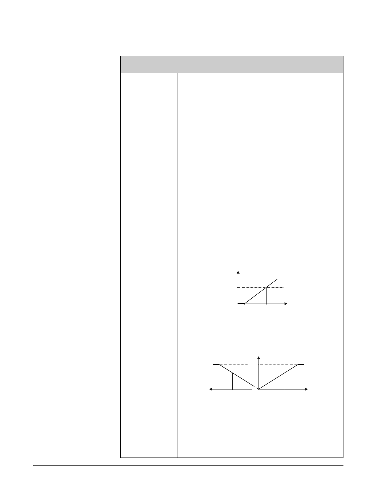
Device Functions Proline Promass 83 7 Block OUTPUTS
Function description
OUTPUTS o PULSE/FREQUENCY OUTPUT (1...2) o CONFIGURATION (FREQUENCY)
MEASURING MODE
(4206)
! Note!
This function is not available unless the FREQUENCY setting was selected in the
OPERATION MODE function (4200).
Use this function to define the measuring mode for the frequency output.
Options:
STANDARD
SYMMETRY
PULSATING FLOW
Factory setting:
STANDARD
Description of the individual options:
•STANDARD
The frequency output signal is proportional to the measured variable. The flow
components outside the scaled measuring range (defined by the VALUE F LOW m and
the VALUE F HIGH n) are not taken into account for signal output.
– If one of the values is defined as equal to the zero flow (e.g. VALUE F LOW =
0 kg/h), no message is given if this value is exceeded or not achieved and the
frequency output retains its value ( 0 Hz in the example). If the other value is
exceeded or not achieved, the message “FREQUENCY OUTPUT AT FULL SCALE
VALUE” appears and the frequency output responds in accordance with the
parameter setting in the function FAILSAFE MODE (4209).
– If both values defined are not equal to the zero flow (for example VALUE F LOW =
–5 kg/h; VALUE F HIGH = 10 kg/h), the message “FREQUENCY OUTPUT AT
FULL SCALE VALUE” appears if the measuring range is exceeded or not achieved
and the frequency output responds in accordance with the parameter settings in the
function FAILSAFE MODE (4209)...
Freq.
125
100
0
➀➁
SYMMETRY
The frequency output signal is independent of the direction of flow (absolute amount of
the measured variable). The VALUE F LOW m and VALUE F HIGH n must have the
same sign (+ or
VALUE F HIGH n (e.g. flow).
-). The VALUE F HIGHo (e.g. backflow) corresponds to the mirrored
Freq.
125
100
0
➀➁➂
Q
A0001279
Q
A0001280
! Note!
• The direction of flow can be output via the configurable relay or status outputs.
• SYMMETRY cannot be selected unless the values in the VALUE F LOW (4204) and
VALUE F HIGH (4205) functions have the same sign or one of the values is zero. If the
values have different signs, SYMMETRY cannot be selected and an
“ASSIGNMENT NOT POSSIBLE” message is displayed.
(continued on next page)
Issue/Rev. 0.2 (12/12) MN0M023 • Page 79

7 Block OUTPUTS Device Functions Proline Promass 83
Function description
OUTPUTS o PULSE/FREQUENCY OUTPUT (1...2) o CONFIGURATION (FREQUENCY)
MEASURING MODE
(continued)
• PULSATING FLOW
If flow is characterized by severe fluctuations as is the case, for example, with
reciprocating pumps, flow components outside the measuring range are buffered,
balanced and output after a maximum delay of 60 seconds. If the buffered data cannot
be processed within approx. 60 seconds, a fault/notice message appears.
Under certain plant conditions, flow values can aggregate in the buffer, for example in
the case of prolonged and unwanted fluid backflow. However, this buffer is reset in all
relevant programming adjustments which affect the frequency output.
Page 80 • MN0M023
Issue/Rev. 0.2 (12/12)
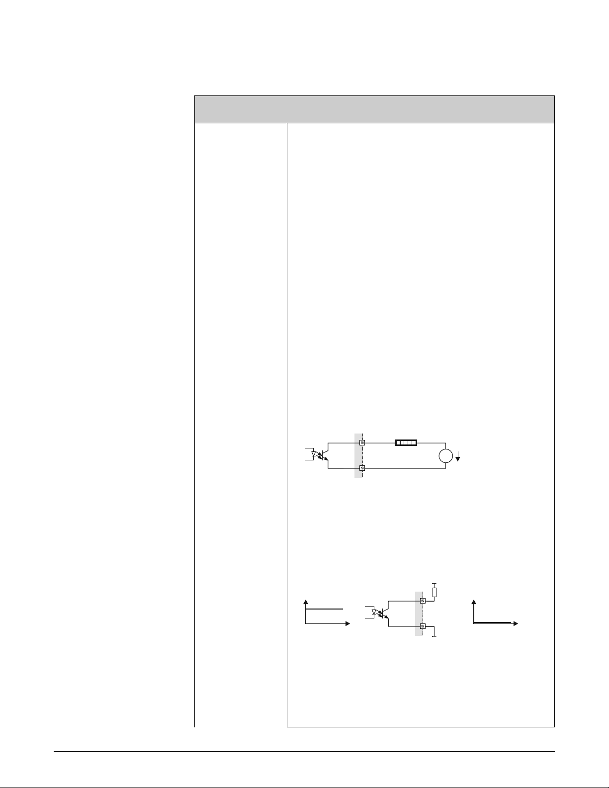
Device Functions Proline Promass 83 7 Block OUTPUTS
Function description
OUTPUTS o PULSE/FREQUENCY OUTPUT (1...2) o CONFIGURATION (FREQUENCY)
OUTPUT SIGNAL
(4207)
! Note!
Function is not available unless the FREQUENCY setting was selected in the
OPERATION MODE (4200) function.
For selecting the output configuration of the frequency output.
Options:
0 = PASSIVE - POSITIVE
1 = PASSIVE - NEGATIVE
2 = ACTIVE - POSITIVE
3 = ACTIVE - NEGATIVE
Factory setting: PASSIVE - POSITIVE
Explanation
• PASSIVE = power is supplied to the frequency output by means of an external power
supply.
• ACTIVE = power is supplied to the frequency output by means of the device-internal
power supply.
Configuring the output signal level (POSITIVE or NEGATIVE) determines the quiescent
behavior (at zero flow) of the frequency output.
The internal transistor is activated as follows:
• If POSITIVE is selected, the internal transistor is activated with a positive signal level.
• If NEGATIVE is selected, the internal transistor is activated with a negative signal
level (0 V).
! Note!
With the passive output configuration, the output signal levels of the frequency output
depend on the external circuit (see examples).
Example for passive output circuit (PASSIVE)
If PASSIVE is selected, the frequency output is configured as an open collector.
m
7
158 3
+
=
U =30VDC
max
-
n
A0001225
m = Open collector
n = External power supply
! Note!
For continuous currents up to 25 mA (I
Example for output configuration PASSIVE-POSITIVE:
Output configuration with an external pull-up resistance.
In the quiescent state (at zero flow), the output signal level at the terminals is 0 V.
U (V)
o
m
t
m = Open collector
n = Pull-Up-Resistance
o = Transistor activation in “POSITIVE” quiescent state (at zero flow)
p = Output signal level in quiescent state (at zero flow)
= 250 mA / 20 ms).
max
U =30VDC
+
max
n
U (V)
p
t
A0004687
(continued on next page)
Issue/Rev. 0.2 (12/12) MN0M023 • Page 81

7 Block OUTPUTS Device Functions Proline Promass 83
Function description
OUTPUTS o PULSE/FREQUENCY OUTPUT (1...2) o CONFIGURATION (FREQUENCY)
OUTPUT SIGNAL
(continued)
In the operating status (flow present), the output signal level changes from 0 V to a
positive voltage level.
U (V)
t
A0001975
Example for output configuration PASSIVE-POSITIVE:
Output configuration with an external pull-down resistance.
In the quiescent state (at zero flow), a positive voltage level is measured via the
pull-down resistance.
U =30VDC
+
max
U (V)
op
m
t
U (V)
n
t
A0004689
m = Open collector
n = Pull-Down-Resistance
o = Transistor activation in “POSITIVE” quiescent state (at zero flow)
p = Output signal level in quiescent state (at zero flow)
In the operating status (flow present), the output signal level changes from a positive
voltage level to 0 V.
U (V)
t
A0001981
Page 82 • MN0M023
Example for output configuration PASSIVE-NEGATIVE:
Output configuration with an external pull-up resistance.
In the quiescent state (at zero flow), the output signal level at the terminals is at a positive
voltage level.
U =30VDC
+
max
n
U (V)
m
t
o
U (V)
p
t
A0004690
m = Open collector
n = Pull-Up-Resistance
o = Transistor activation in “NEGATIVE” quiescent state (at zero flow)
p = Output signal level in quiescent state (at zero flow)
In the operating status (flow present), the output signal level changes from a positive
voltage level to 0 V.
U (V)
t
(continued on next page)
Issue/Rev. 0.2 (12/12)
A0001981

Device Functions Proline Promass 83 7 Block OUTPUTS
Function description
OUTPUTS o PULSE/FREQUENCY OUTPUT (1...2) o CONFIGURATION (FREQUENCY)
OUTPUT SIGNAL
(continued)
Example for active output circuit (ACTIVE):
With an active circuit, the internal power supply is 24 V.
The frequency output is short-circuit proof.
+
➀
=
-
158 3
➁
7
m = 24 V DC internal power supply
A0004691
n = Short-circuit proof output
The signal levels are to be seen as analogous to the passive circuit.
The following applies for the output configuration ACTIVE-POSITIVE:
In the quiescent state (at zero flow), the output signal level at the terminals is 0 V.
U
24 V
0V
In the operating status (flow present), the output signal level changes from 0 V to a
positive voltage level.
U
24 V
0V
The following applies for the output configuration ACTIVE-NEGATIVE:
In the quiescent state (at zero flow), the output signal level at the terminals is at a positive
voltage level.
U
24 V
t
t
A0004694
A0004692
0V
t
A0004693
In the operating status (flow present), the output signal level changes from a positive
voltage level to 0 V.
U
24 V
0V
t
A0004710
Issue/Rev. 0.2 (12/12) MN0M023 • Page 83

7 Block OUTPUTS Device Functions Proline Promass 83
Function description
OUTPUTS o PULSE/FREQUENCY OUTPUT (1...2) o CONFIGURATION (FREQUENCY)
TIME CONSTANT
(4208)
! Note!
This function is not available unless the FREQUENCY setting was selected in the
OPERATION MODE function (4200).
Use this function to enter a time constant defining how the frequency output signal reacts
to severely fluctuating measured variables, either very quickly (enter a low time constant)
or with damping (enter a high time constant).
User input:
Fixed-point number 0.00...100.00 s
Factory setting:
0.00 s
FAILSAFE MODE
(4209)
FAILSAFE VALUE
(4211)
! Note!
This function is not available unless the FREQUENCY setting was selected in the
OPERATION MODE function (4200).
For safety reasons it is advisable to ensure that the frequency output assumes a predefined
state in the event of a fault. The setting you select here affects only the frequency output.
It has no effect on other outputs and the display (e.g. totalizers).
Options:
FALLBACK VALUE
Output is 0 Hz.
FAILSAFE VALUE
Output is the frequency specified in the FAILSAFE VALUE function (4211).
HOLD VALUE
Measured value output is based on the last measured value saved before the error
occurred.
ACTUAL VALUE
Measured value output is based on the current flow measurement. The fault is ignored .
Factory setting:
FALLBACK VALUE
! Note!
This function is not available unless FREQUENCY was selected in the
OPERATION MODE function (4200) and FAILSAFE VALUE was selected
in the FAILSAFE MODE function (4209).
Page 84 • MN0M023
Use this function to define the frequency that the measuring device outputs in the event
of an error.
User input:
max. 5-digit number: 0...12500 Hz
Factory setting:
12500 Hz
Issue/Rev. 0.2 (12/12)

Device Functions Proline Promass 83 7 Block OUTPUTS
Function description
OUTPUTS o PULSE/FREQUENCY OUTPUT (1...2) o CONFIGURATION (PULSE)
ASSIGN PULSE
(4221)
! Note!
This function is not available unless the PULSE setting was selected in the OPERATION
MODE function (4200).
Use this function to assign a measured variable to the pulse output.
Options:
OFF
MASS FLOW
VOLUME FLOW
CORRECTED VOLUME FLOW
Advanced options with optional software package CONCENTRATION:
TARGET MASS
TARGET VOLUME
TARGET CORRECTED VOLUME
CARRIER MASS
CARRIER VOLUME
CARRIER CORRECTED VOLUME
Factory setting:
MASS FLOW
PULSE VALUE
(4222)
! Note!
If you select OFF, the only function shown in the CONFIGURATION function group is
this function, in other words ASSIGN PULSE (4221).
! Note!
This function is not available unless the PULSE setting was selected in the OPERATION
MODE function (4200).
Use this function to define the flow at which a pulse is triggered. These pulses can be
totaled by an external totalizer, and the total flow quantity since measuring started can be
registered in this way.
User input:
5-digit floating-point number [unit]
Factory setting:
depends on nominal diameter and country,
[value] [kg or lb] / impulse;
corresponds to the factory setting for the pulse value (see page 189 ff.).
! Note!
The appropriate unit is taken from the UNIT MASS (0401), UNIT VOLUME (0403) or
UNIT CORRECTED VOLUME (0405) function (see page 17 or page 19).
Issue/Rev. 0.2 (12/12) MN0M023 • Page 85

7 Block OUTPUTS Device Functions Proline Promass 83
Function description
OUTPUTS o PULSE/FREQUENCY OUTPUT (1...2) o CONFIGURATION (PULSE)
PULSE WIDTH
(4223)
! Note!
This function is not available unless the PULSE setting was selected in the OPERATION
MODE function (4200).
Use this function to enter the pulse width of the output pulse.
User input:
0.05...2000 ms
Factory setting:
100 ms
Pulse output is always with the pulse width (B) entered in this function. The pauses (P)
between the individual pulses are automatically configured. However, they must at least
correspond to the pulse width (B = P).
transistor transistor
B
conducting
nonconducting
B = Pulse width entered (the illustration applies to positive pulses)
P = Pauses between the individual pulses
B<P
tt
P
conducting
nonconducting
B
P
B=P
A0001233-en
! Note!
When entering the pulse width, select a value that can still be processed by an external
totalizer (e.g. mechanical totalizer, PLC, etc.).
" Caution!
If the pulse number or frequency resulting from the pulse value entered (see function
PULSE VALUE (4222) on page 85) and from the current flow is too large to maintain the
pulse width selected (the time interval is smaller than the pulse width B entered), a
system error message is generated (# 359...362, pulse buffer) after approx. 5 seconds
buffer/balance time.
Page 86 • MN0M023
Issue/Rev. 0.2 (12/12)

Device Functions Proline Promass 83 7 Block OUTPUTS
Function description
OUTPUTS o PULSE/FREQUENCY OUTPUT (1...2) o CONFIGURATION (PULSE)
MEASURING MODE
(4225)
! Note!
This function is not available unless the PULSE setting was selected in the OPERATION
MODE function (4200).
Use this function to define the measuring mode for the pulse output.
Options:
STANDARD
Only positive flow components are totaled. Negative components are not taken into
account.
SYMMETRY
Positive and negative flow components are taken into account.
! Note!
The direction of flow can be output via the relay output.
PULSATING FLOW
If flow is characterized by severe fluctuations as is the case, for example, with
reciprocating pumps, the positive and negative flow components are totaled, with the
signs taken into account (e.g.
Flow components outside the maximum pulse number per second (value/width) are
buffered, balanced and output after a maximum delay of 60 seconds. If the buffered data
cannot be processed within approx. 60 seconds, a fault/notice message appears.
-10 l and +25 l = 15 l).
Under certain plant conditions, flow values can aggregate in the buffer, for example in the
case of prolonged and unwanted fluid backflow. However, this buffer is reset in all
relevant programming adjustments which affect the pulse output.
STANDARD REVERSE
Only negative flow components are totaled. Positive components are not taken into
account.
Factory setting:
STANDARD
Issue/Rev. 0.2 (12/12) MN0M023 • Page 87

7 Block OUTPUTS Device Functions Proline Promass 83
Function description
OUTPUTS o PULSE/FREQUENCY OUTPUT (1...2) o CONFIGURATION (PULSE)
OUTPUT SIGNAL
(4226)
! Note!
Function is not available unless the PULSE setting was selected in the OPERATION
MODE (4200) function.
For selecting the output configuration of the pulse output.
Options:
0 = PASSIVE - POSITIVE
1 = PASSIVE - NEGATIVE
2 = ACTIVE - POSITIVE
3 = ACTIVE - NEGATIVE
Factory setting: PASSIVE - POSITIVE
Explanation
• PASSIVE = power is supplied to the pulse output by means of an external power
supply.
• ACTIVE = power is supplied to the pulse output by means of the device-internal
power supply.
Configuring the output signal level (POSITIVE or NEGATIVE) determines the quiescent
behavior (at zero flow) of the pulse output.
The internal transistor is activated as follows:
• If POSITIVE is selected, the internal transistor is activated with a positive signal level.
• If NEGATIVE is selected, the internal transistor is activated with a negative signal
level (0 V).
! Note!
With the passive output configuration, the output signal levels of the pulse output depend
on the external circuit (see examples).
Example for passive output circuit (PASSIVE)
If PASSIVE is selected, the pulse output is configured as an open collector.
m
7
158 3
+
=
U =30VDC
max
-
n
A0001225
m = Open collector
n = External power supply
! Note!
For continuous currents up to 25 mA (I
Example for output configuration PASSIVE-POSITIVE:
Output configuration with an external pull-up resistance.
In the quiescent state (at zero flow), the output signal level at the terminals is 0 V.
U (V)
o
m
t
m = Open collector
n = Pull-Up-Resistance
o = Transistor activation in “POSITIVE” quiescent state (at zero flow)
p = Output signal level in quiescent state (at zero flow)
= 250 mA / 20 ms).
max
U =30VDC
+
max
n
U (V)
t
p
A0004687
Page 88 • MN0M023
(continued on next page)
Issue/Rev. 0.2 (12/12)
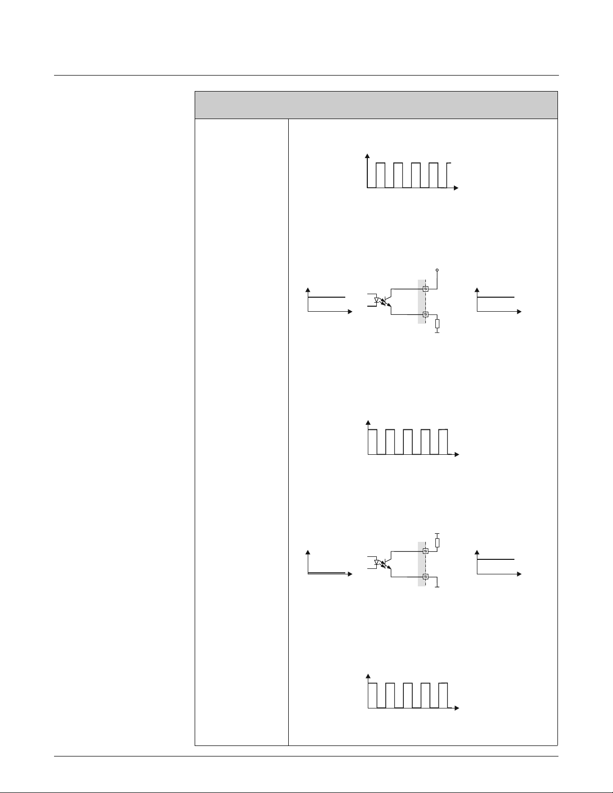
Device Functions Proline Promass 83 7 Block OUTPUTS
Function description
OUTPUTS o PULSE/FREQUENCY OUTPUT (1...2) o CONFIGURATION (PULSE)
OUTPUT SIGNAL
(continued)
In the operating status (flow present), the output signal level changes from 0 V to a
positive voltage level.
U (V)
t
Example for output configuration PASSIVE-POSITIVE:
Output configuration with an external pull-down resistance.
In the quiescent state (at zero flow), a positive voltage level is measured via
the pull-down resistance.
U =30VDC
+
max
A0001975
U (V)
op
m
t
U (V)
n
t
A0004689
m = Open collector
n = Pull-Down-Resistance
o = Transistor activation in “POSITIVE” quiescent state (at zero flow)
p = Output signal level in quiescent state (at zero flow)
In the operating status (flow present), the output signal level changes from a positive
voltage level to 0 V.
U (V)
t
Example for output configuration PASSIVE-NEGATIVE:
Output configuration with an external pull-up resistance.
In the quiescent state (at zero flow), the output signal level at the terminals is at a positive
voltage level.
U =30VDC
+
max
n
U (V)
m
U (V)
A0001981
t
o
t
p
A0004690
m = Open collector
n = Pull-Up-Resistance
o = Transistor activation in “NEGATIVE” quiescent state (at zero flow)
p = Output signal level in quiescent state (at zero flow)
In the operating status (flow present), the output signal level changes from a positive
voltage level to 0 V.
U (V)
t
(continued on next page)
Issue/Rev. 0.2 (12/12) MN0M023 • Page 89
A0001981
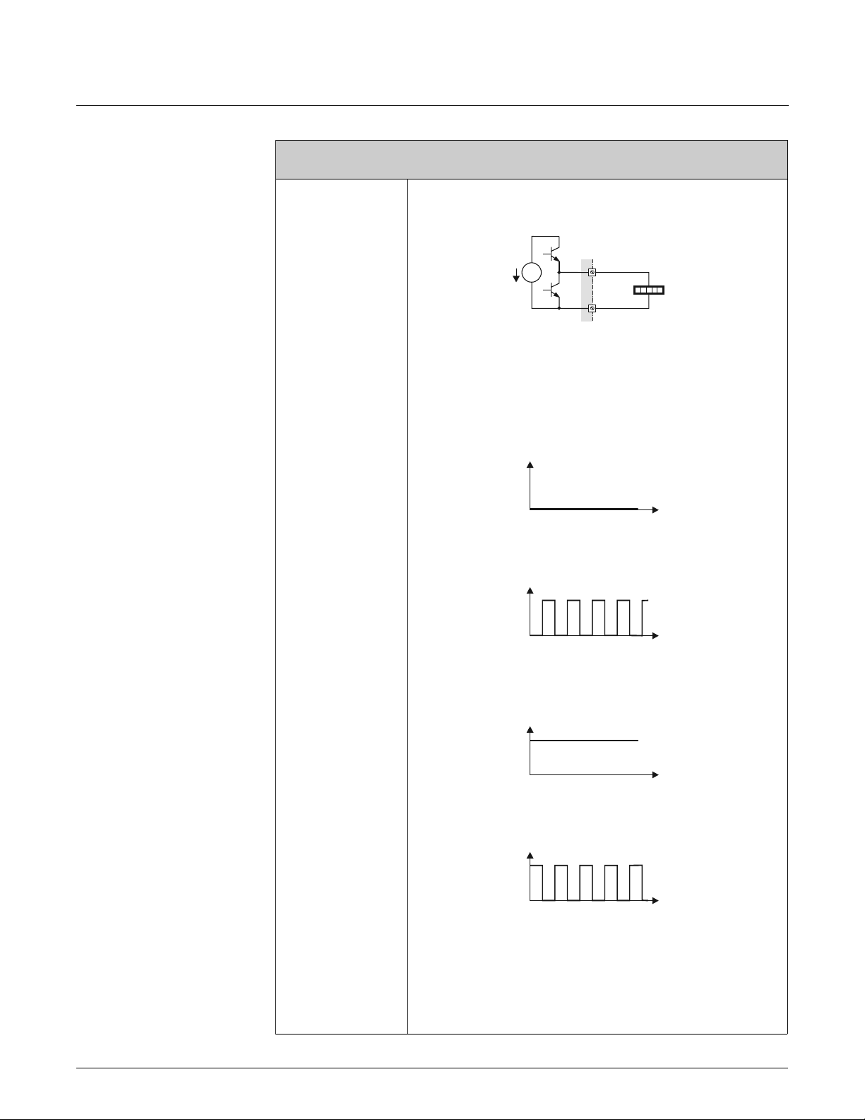
7 Block OUTPUTS Device Functions Proline Promass 83
Function description
OUTPUTS o PULSE/FREQUENCY OUTPUT (1...2) o CONFIGURATION (PULSE)
OUTPUT SIGNAL
(continued)
Example for active output circuit (ACTIVE):
With an active circuit, the internal power supply is 24 V.
The pulse output is short-circuit proof.
+
➀
=
-
158 3
➁
7
m = 24 V DC internal power supply
A0004691
n = Short-circuit proof output
The signal levels are to be seen as analogous to the passive circuit.
The following applies for the output configuration ACTIVE-POSITIVE:
In the quiescent state (at zero flow), the output signal level at the terminals is 0 V.
U
24 V
0V
In the operating status (flow present), the output signal level changes from 0 V to a
positive voltage level.
U
24 V
0V
The following applies for the output configuration ACTIVE-NEGATIVE:
In the quiescent state (at zero flow), the output signal level at the terminals is at a positive
voltage level.
U
24 V
t
t
A0004694
A0004692
Page 90 • MN0M023
0V
t
A0004693
In the operating status (flow present), the output signal level changes from a positive
voltage level to 0 V.
U
24 V
0V
t
A0004710
Issue/Rev. 0.2 (12/12)

Device Functions Proline Promass 83 7 Block OUTPUTS
Function description
OUTPUTS o PULSE/FREQUENCY OUTPUT (1...2) o CONFIGURATION (PULSE)
FAILSAFE MODE
(4227)
! Note!
This function is not available unless the PULSE setting was selected in the OPERATION
MODE function (4200).
For safety reasons it is advisable to ensure that the pulse output assumes a predefined
state in the event of a fault. The setting you select here affects only the pulse output. It
has no effect on other outputs and the display (e.g. totalizers).
Options:
FALLBACK VALUE
Output is 0 pulse.
ACTUAL VALUE
Measured value output is based on the current flow measurement. The fault is ignored.
Factory setting:
FALLBACK VALUE
Issue/Rev. 0.2 (12/12) MN0M023 • Page 91

7 Block OUTPUTS Device Functions Proline Promass 83
Function description
OUTPUTS o PULSE/FREQUENCY OUTPUT (1...2) o CONFIGURATION (STATUS)
ASSIGN STATUS
(4241)
! Note!
This function is not available unless the STATUS setting was selected in the OPERATION
MODE function (4200).
Use this function to assign a switching function to the status output.
Options:
OFF
ON (operation)
FAULT MESSAGE
NOTICE MESSAGE
FAULT MESSAGE or NOTICE MESSAGE
EMPTY PIPE DETECTION (only with active function)
FLOW DIRECTION
MASS FLOW LIMIT VALUE
VOLUME FLOW LIMIT VALUE
CORRECTED VOLUME FLOW LIMIT VALUE
DENSITY LIMIT VALUE
REFERENCE DENSITY LIMIT VALUE
TEMPERATURE LIMIT VALUE
TOTALIZER 1 LIMIT VALUE
TOTALIZER 2 LIMIT VALUE
TOTALIZER 3 LIMIT VALUE
Advanced options with optional software package BATCHING:
BATCH RUNNING
> BATCH TIME
>< BATCH QUANTITIES (< min. / > max. batching quantity)
PROGRESS NOTE (batching end approaching)
! Note!
The only options available are the monitoring functions (7240 to 7243) which have a
value not equal to zero (max. 3).
Advanced options with optional software package CONCENTRATION:
LIMIT TARGET MASS FLOW
LIMIT TARGET % MASS PROPORTION FLOW
LIMIT TARGET VOLUME FLOW
LIMIT TARGET % VOLUME PROPORTION FLOW
LIMIT TARGET CORRECTED VOLUME FLOW
LIMIT CARRIER MASS FLOW
LIMIT CARRIER % MASS PROPORTION FLOW
LIMIT CARRIER VOLUME FLOW
LIMIT CARRIER % VOLUME PROPORTION FLOW
LIMIT CARRIER CORRECTED VOLUME FLOW
LIMIT % BLACK LIQUOR
LIMIT °BAUME > 1
LIMIT °BAUME < 1
LIMIT °API
LIMIT °PLATO
LIMIT °BALLING
LIMIT °BRIX
LIMIT OTHERS (_ _ _ _ flexible concentration)
Advanced options with optional software package ADVANCED DIAGNOSIS:
LIMIT MASS FLOW DEVIATION
LIMIT DENSITY DEVIATION
LIMIT REFERENCE DENSITY DEVIATION
LIMIT TEMPERATURE DEVIATION
LIMIT TUBE DAMPING DEVIATION
LIMIT ELECTRODYNAMIC SENSOR DEVIATION
LIMIT OPERATING FREQUENCY DEVIATION
LIMIT TUBE DAMPING DEVIATION
Page 92 • MN0M023
(continued on next page)
Issue/Rev. 0.2 (12/12)

Device Functions Proline Promass 83 7 Block OUTPUTS
Function description
OUTPUTS o PULSE/FREQUENCY OUTPUT (1...2) o CONFIGURATION (STATUS)
ASSIGN STATUS
(continued)
Factory setting:
FAULT MESSAGE
! Note!
• The behavior of the status output is a normally closed behavior, in other words the
output is closed (transistor conductive) when normal, error-free measuring is in
progress.
– “normal, error-free” operation: Flow direction = forwards; limit values = not
exceeded; no empty or partially filled measuring tube (EPD/OED); no fault or notice
message present.
– Switching response like relay output, page 109
• If you select OFF, the only function shown in the CONFIGURATION function group is
this function, in other words ASSIGN STATUS (4241).
• Switching response like relay output, see page 109.
ON-VALUE
(4242)
SWITCH-ON DELAY
(4243)
! Note!
This function is not available unless STATUS was selected in the OPERATION MODE
function (4200) and LIMIT VALUE or FLOW DIRECTION was selected in the ASSIGN
STATUS function (4241).
Use this function to assign a value to the switch-on point (activation of the status output).
The value can be higher or lower than the switch-off point. Positive or negative values
are permissible, depending on the measured variable in question (e.g. mass flow, totalizer
reading).
User input:
5-digit floating-point number [unit]
Factory setting:
0 [kg/h] or 2 [kg/l] or 200 [°C]
! Note!
• If SYMMETRY is selected in the function MEASURING MODE (4246) and values with
different signs are entered for the switch-on and switch-off points, the notice message
“INPUT RANGE EXCEEDED” appears.
• Only the switch-on point is available for flow direction output (no switch-off point). If
you enter a value not equal to the zero flow (e.g. 5), the difference between the zero
flow and the value entered corresponds to half the switchover hysteresis.
! Note!
This function is not available unless STATUS was selected in the OPERATION MODE
function (4200) and LIMIT VALUE or FLOW DIRECTION was selected in the ASSIGN
STATUS function (4241).
Use this function to define a delay (0...100 seconds) for the switch-on (i.e. signal changes
from “not conductive” to “conductive”) of the status output. The delay starts when the
limit value is reached. The status output does switch when the delay has timed out and
the switch on condition has been valid over the delay time.
User input:
fixed-point number: 0.0...100.0 s
Factory setting:
0.0 s
Issue/Rev. 0.2 (12/12) MN0M023 • Page 93

7 Block OUTPUTS Device Functions Proline Promass 83
Function description
OUTPUTS o PULSE/FREQUENCY OUTPUT (1...2) o CONFIGURATION (STATUS)
OFF-VALUE
(4244)
! Note!
This function is not available unless STATUS was selected in the OPERATION MODE
function (4200) and a LIMIT VALUE was selected in the ASSIGN STATUS function
(4241).
Use this function to assign a value to the switch-off point (deactivation of the status
output). The value can be higher or lower than the switch-on point. Positive and negative
values are permissible, depending on the measured variable in question (e.g. mass flow,
totalizer reading).
User input:
5-digit floating-point number [unit]
Factory setting:
0 [kg/h] or 2 [kg/l] or 200 [°C]
! Note!
• The appropriate unit is taken from the function UNIT VOLUME FLOW (0402) or
UNIT MASS FLOW (0400).
• If SYMMETRY is selected in the function MEASURING MODE (4246) and values with
different signs are entered for the switch-on and switch-off points, the notice message
“INPUT RANGE EXCEEDED” appears.
SWITCH-OFF DELAY
(4245)
! Note!
This function is not available unless the STATUS setting was selected in the OPERATION
MODE function (4200).
Use this function to define a delay (0...100 seconds) for the switch-off (i.e. signal changes
from “conductive” to “not conductive”) of the status output. The delay starts when the
limit value is reached. The status output does switch when the delay has timed out and
the switch off condition has been valid over the delay time.
User input:
fixed-point number: 0.0...100.0 s
Factory setting:
0.0 s
Page 94 • MN0M023
Issue/Rev. 0.2 (12/12)
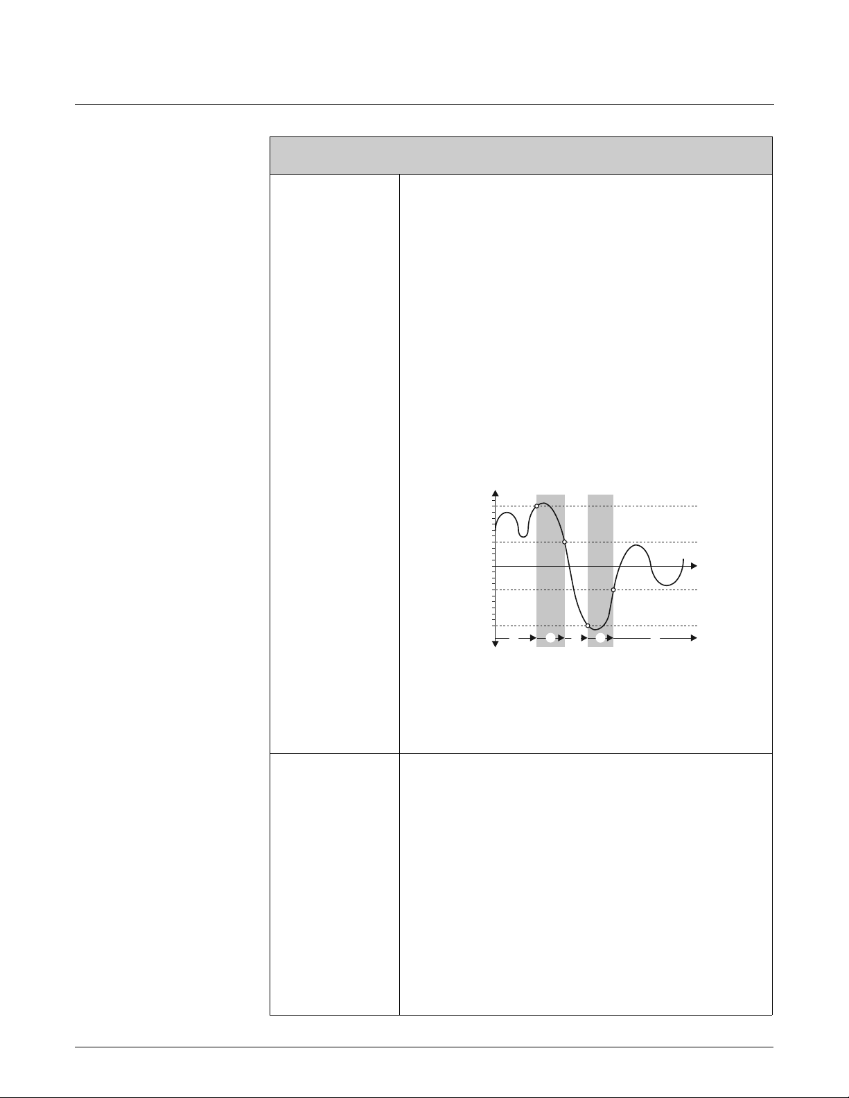
Device Functions Proline Promass 83 7 Block OUTPUTS
Function description
OUTPUTS o PULSE/FREQUENCY OUTPUT (1...2) o CONFIGURATION (STATUS)
MEASURING MODE
(4246)
! Note!
This function is not available unless STATUS was selected in the OPERATION MODE
function(4200) and the status output was assigned a limit value.
Use this function to define the measuring mode for the status output.
Options:
STANDARD
The status output signal switches at the defined switch points.
SYMMETRY
The status output signal switches at the defined switch points, irrespective of the sign. If
you define a switch point with a positive sign, the status output signal switches as soon as
the value is reached in the negative direction (negative sign), (see illustration).
Factory setting:
STANDARD
Example for the SYMMETRY measuring mode:
Switch-on point Q = 4, Switch-off point Q = 10
m = Status output switched on (conductive)
n = Status output switched off (nonconductive)
Q
10
TIME CONSTANT
(4247)
4
0
-4
-10
➀➁➀➁ ➀
➀
t
A0001247
! Note!
• SYMMETRY cannot be selected unless the values in the ON-VALUE (4242) and OFF-
VALUE (4244) functions have the same sign or one of the values is zero.
• If the values have different signs, SYMMETRY cannot be selected and an
“ASSIGNMENT NOT POSSIBLE” message is displayed.
! Note!
This function is not available unless the STATUS setting was selected in the OPERATION
MODE function (4200).
Use this function to enter a time constant defining how the measuring signal reacts to
severely fluctuating measured variables, either very quickly (enter a low time constant) or
with damping (enter a high time constant). Damping acts on the measuring signal before
the switch status changes, and consequently before switch-on or switch-off delay is
activated. The purpose of damping, therefore, is to prevent the status output changing
state continuously in response to fluctuations in flow.
User input:
Fixed-point number 0.00 to 100.00 s
Factory setting:
0.00 s
Issue/Rev. 0.2 (12/12) MN0M023 • Page 95

7 Block OUTPUTS Device Functions Proline Promass 83
7.2.2 Function group OPERATION
OUTPUTS E
OUTPUTS o PULSE/FREQUENCY OUTPUT (1...2) o OPERATION (FREQUENCY)
ACTUAL FREQUENCY
(4301)
CURRENT OUTPUT 1 EAA
CURRENT OUTPUT 2 EAB
CURRENT OUTPUT 3 EAC
PULSE/FREQ. OUTPUT 1 ECA
PULSE/FREQ. OUTPUT 2 ECB
CONFIGURATION 420
OPERATION 430
CONFIGURATION 420
OPERATION 430
Function description
! Note!
This function is not available unless the FREQUENCY setting was selected in the
OPERATION MODE function (4200).
Use this function to view the computed actual value of the output frequency.
Display:
0...12500 Hz
SIMULATION
FREQUENCY
(4302)
! Note!
This function is not available unless the FREQUENCY setting was selected in the
OPERATION MODE function (4200).
Use this function to activate simulation of the frequency output.
Options:
OFF
ON
Factory setting:
OFF
! Note!
• The “SIMULATION FREQUENCY OUTPUT” message indicates that simulation is
active.
• The measuring device continues to measure while simulation is in progress, i.e. the
current measured values are output correctly via the other outputs.
" Caution!
The setting is not saved if the power supply fails.
Page 96 • MN0M023
Issue/Rev. 0.2 (12/12)

Device Functions Proline Promass 83 7 Block OUTPUTS
Function description
OUTPUTS o PULSE/FREQUENCY OUTPUT (1...2) o OPERATION (FREQUENCY)
VALUE SIMULATION
FREQUENCY
(4303)
! Note!
This function is not available unless FREQUENCY was selected in the OPERATION
MODE function (4200) and the SIMULATION FREQUENCY function (4302) is active
(= ON).
Use this function to define a free selectable frequency value (e.g. 500 Hz) which should
be output at the frequency output (with maximum pulse frequency or shortened
minimum pulse width). This value is used to test downstream devices and the measuring
device itself.
User input:
0...12500 Hz
Factory setting:
0 Hz
" Caution!
The setting is not saved if the power supply fails.
Issue/Rev. 0.2 (12/12) MN0M023 • Page 97

7 Block OUTPUTS Device Functions Proline Promass 83
Function description
OUTPUTS o PULSE/FREQUENCY OUTPUT (1...2) o OPERATION (PULSE)
SIMULATION
PULSE(4322)
! Note!
This function is not available unless the PULSE option was selected in the OPERATION
MODE function.
Use this function to activate simulation of the pulse output.
Options:
OFF
COUNTDOWN
The pulses specified in the VALUE SIMULATION PULSE function are output.
CONTINUOUSLY
Pulses are continuously output with the pulse width specified in the PULSE WIDTH
function. Simulation is started once the CONTINUOUSLY option is confirmed with the
F key.
! Note!
Simulation is started by confirming the CONTINUOUSLY option with the F key. The
simulation can be switched off again via the SIMULATION PULSE function.
Factory setting:
OFF
! Note!
• The notice message #631 “SIM. PULSE” indicates that simulation is active.
• The on/off ratio is 1:1 for both types of simulation.
• The measuring device continues to measure while simulation is in progress, i.e. the
current measured values are output correctly via the other outputs.
VALUE SIMULATION
PULSE
(4323)
" Caution!
The setting is not saved if the power supply fails.
! Note!
This function is not available unless the COUNTDOWN option was selected in the
SIMULATION PULSE function.
Use this function to specify the number of pulses (e.g. 50) which are output during the
simulation. This value is used to test downstream devices and the measuring device itself.
The pulses are output with the pulse width specified in the PULSE WIDTH function. The
on/off ratio is 1:1.
Simulation is started once the specified value is confirmed with the F key. The display
remains at 0 if the specified pulses have been output.
User input:
0...10 000
Factory setting:
0
! Note!
Simulation is started by confirming the simulation value with the F key. The simulation
can be switched off again via the SIMULATION PULSE function.
" Caution!
The setting is not saved if the power supply fails.
Page 98 • MN0M023
Issue/Rev. 0.2 (12/12)

Device Functions Proline Promass 83 7 Block OUTPUTS
Function description
OUTPUTS o PULSE/FREQUENCY OUTPUT (1...2) o OPERATION (STATUS)
ACTUAL STATUS
(4341)
! Note!
This function is not available unless the STATUS setting was selected in the OPERATION
MODE function (4200).
Use this function to check the current status of the status output.
Display:
NOT CONDUCTIVE
CONDUCTIVE
SIMULATION SWITCH
POINT
(4342)
VALUE SIMULATION
SWITCH POINT
(4343)
! Note!
This function is not available unless the STATUS setting was selected in the OPERATION
MODE function (4200).
Use this function to activate simulation of the status output.
Options:
OFF
ON
Factory setting:
OFF
! Note!
• The “SIMULATION STATUS OUTPUT” message indicates that simulation is active.
• The measuring device continues to measure while simulation is in progress, i.e. the
current measured values are output correctly via the other outputs.
" Caution!
The setting is not saved if the power supply fails.
! Note!
This function is not available unless STATUS was selected in the OPERATION MODE
function (4200) and the SIMULATION SWITCH POINT function (4342) is active
(= ON).
Use this function to define the switching response of the status output during the
simulation. This value is used to test downstream devices and the measuring device itself.
Options:
NOT CONDUCTIVE
CONDUCTIVE
Factory setting:
NOT CONDUCTIVE
" Caution!
The setting is not saved if the power supply fails.
Issue/Rev. 0.2 (12/12) MN0M023 • Page 99

7 Block OUTPUTS Device Functions Proline Promass 83
7.2.3 Function group INFORMATION
OUTPUTS E
TERMINAL NUMBER
(4380)
CURRENT OUTPUT 1 EAA
CURRENT OUTPUT 2 EAB
CURRENT OUTPUT 3 EAC
PULSE/FREQ. OUTPUT 1 ECA
CONFIGURATION 420
OPERATION 430
INFORMATION 438
PULSE/FREQ. OUTPUT 2 ECB
CONFIGURATION 420
OPERATION 430
INFORMATION 438
Function description
OUTPUTS o PULSE/FREQ. OUTP. (1...2) o INFORMATION
Use this function to view the numbers of the terminals (in the connection compartment)
and the polarity used by the pulse/frequency output.
Page 100 • MN0M023
Issue/Rev. 0.2 (12/12)
 Loading...