

FläktGroup Multi-DENCO Operation Manual

Multi
-DENCO
®
OPERATION MANUAL

Table of Contents Multi-DENCO
2 FläktGroup DC-2013-0101-GB • Subject to modifications • R4-05/2018
1 Overview of Units and Scope of Supply ................................. 13
1.1 Introduction .............................................................................................. 13
1.2 Model number explained .......................................................................... 13
1.3 Product series overview ........................................................................... 14
1.4 DENCO-OfficeCool .................................................................................. 15
1.5 Scope of supply ....................................................................................... 15
1.6 Accessories and special equipment ......................................................... 15
1.7 Directives and regulations ........................................................................ 15
1.8 References within manual ................ ... .... ... ............................................. . 16
2 Safety and User Information .................................................... 17
2.1 Availability of the operation manual ......................................................... 17
2.2 Scope of the operation manual ................................................................ 17
2.3 Document format ..................................................................................... 18
2.4 Signs used within this manual .................................................................. 19
2.5 Labelling of safety information ................................................................. 21
2.6 Safety-conscious working ........................................................................ 23
2.7 Proper use ....................................................................... .... ... ... ... ... ........ 25
2.8 Modifications and changes ...................................................................... 25
2.9 Spare parts .............................................................................................. 25
2.10 Disposal ................................................................................................... 26
2.11 P ersonnel selec tion and qualification ............................ ... .... ... ... ... ... .... ... . 26
2.12 N oise ................................................... .................................................... . 26
2.13 Environmental considerations .................................................................. 26
3 Technical Description ............................................................... 27
3.1 Unit description ........................................................................................ 27
3.2 Operating limits ........................................................................................ 28
3.3 Operating modes ..................................................................................... 28
3.4 Operating strategies ................................................................................. 29
3.5 Components .................................. ...................... ....................... .............. 31
3.6 Heat rejection systems ............................................................................. 33
4 Shipping and Storage ............................................................... 35
4.1 Delivery .................................................................................................... 35
4.2 Handling ..................................... ...................................................... ........ 35
4.3 Storage .................................................................................................... 36
5 Installation ................................................................................. 37
5.1 Requirements and considerations ................................ ... .... ... ... ... ... .... ... . 37
5.2 Substructures ...................................... ..................................................... 39
5.3 Unit placement ......................................................................................... 41
5.4 Clearance and Access ............................................................................. 42
5.5 Installing enclosed accessories ............................................................... 44
5.6 Installation of outdoor units ...................................................................... 47
5.7 Fan touch protection ........... ... .... ... ... ... .... ... .......................................... ... . 50
5.8 EC Declaration of Conformity .................................................................. 50
6 Medium Connections ................................................................ 52
6.1 Requirements ...................................... ....................... .......................... .... 52
6.2 Connecting refrigeration pipework ........................................................... 52
6.3 Refrigerant pipework testing procedures ................................................. 60
6.4 Humidifier water connections (optional) ................................................... 62
6.5 Connecting condensate drain .................................................................. 64

Multi-DENCO Table of Contents
FläktGroup DC-2013-0101-GB • Subject to modifications • R4-05/2018 3
6.6 Connecting water pipework ...................................................................... 65
7 Electrical Connections ............................................................. 70
7.1 Requirements ........................................................................................... 70
7.2 Connecting mains power supply ............................................................... 71
7.3 Connecting outdoor unit ............................................................................ 72
7.4 Connecting signal cabling ......................................................................... 74
7.5 Customer terminals on C5-12 unit controller ............................................ 76
8 Commissioning ......................................................................... 77
8.1 Requirements ........................................................................................... 77
8.2 Pre-commissioning procedure .................................................................. 78
8.3 Commissioning procedure ........................................................................ 83
8.4 Post-commissioning procedure ................................................................ 93
9 Operation ................................................................................... 94
9.1 Requirements ........................................................................................... 94
9.2 General operation .. ... .... ... ......................................................................... 94
9.3 Alarms and error messages ...................................................................... 96
10 Servicing and Maintenance ...................................................... 97
10.1 Maintenance access ........................... ...................................................... 98
10.2 Servicing ............................................. ...................................................... 98
10.3 Refrigerant leak testing ........................................................................... 100
10.4 Compressor care .................................................................................... 100
10.5 Humidifier maintenance (if fitted) .................................................. ... ....... 100
10.6 Closing down procedure ......................................................................... 101
10.7 Logbook & EU Regulation ...................................................................... 102
11 Fault Finding and Troubleshooting ....................................... 103
11.1 Common Issues ..................................... .... ... ... ... .................................... 104
12 Dismantling and Disposal ...................................................... 106
12.1 Dismantling ......................................... .................................................... 106
12.2 Disposal .............................................................................. .................... 107
13 Appendix .................................................................................. 108
13.1 Pre-Commissioning Checklist (DQA 880) ............................................... 109
13.2 Pressure Test Certificate (DQA 653) ...................................................... 112
13.3 Multi-DENCO Commissioning Report (DQA 890) .................................. 113
PROTECTION NOTICES
The reproduction, distribution and utilization of this document as well as the communication of its contents to others without
express authorization is prohibited. Offenders will be held liable for the payment of damages. All rights reserved in the
event of the grant of a patent, utility model or design.
Multi-DENCO
4 FläktGroup DC-2013-0101-GB • Subject to modifications • R4-05/2018
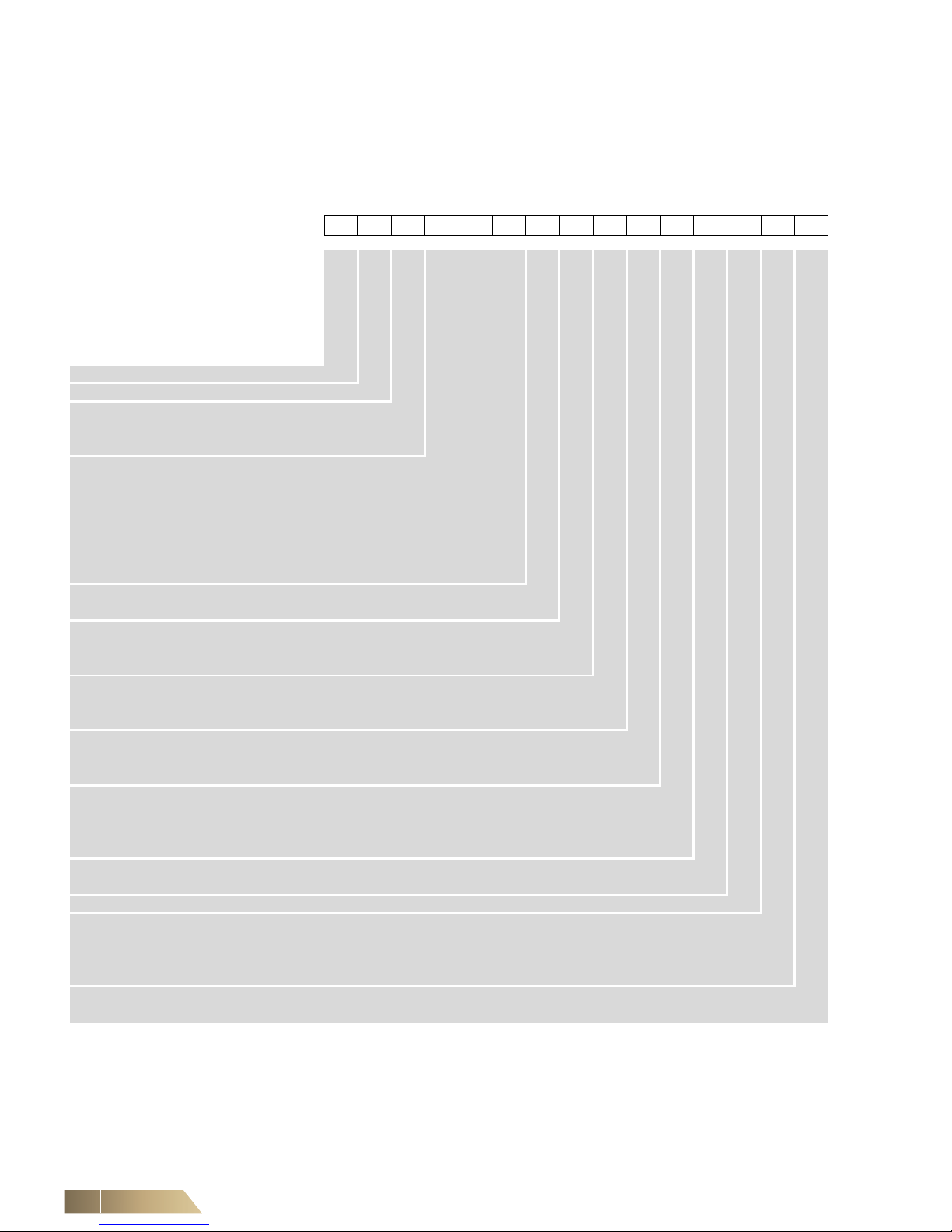
The following pages demonstrate the possible type code and options for a
Multi-DENCO unit. The DENCO OfficeCool short type code is listed on page 12.
Please note that the type code is subject to updates and addition due to our con tinuous
improvement process, therefore for the late st op tio ns availa b le ple ase contact your
local office.
* Not available for X-Version
Basic Unit
Product
Range
Cooling system
Unit size
Air flow direction
Panel configuration
Heat exchanger
Compressor control
Humidifier
Filter
Fan
Heating
Power supply
D DENCO
M Multi-DENCO
A Air cooled
C Chilled Water
X Split System
010 Size 010
018 Size 018
030 Size 030
045 Size 045
065 Size 065*
092 Size 092*
130 Size 130*
D Downflow
U Upflow
P Front full height panel
F Front air inlet grille panel
L Front low level air discharge panel
S Standard heat exchanger
C CombiCool
L Large heat exchanger
I Inverter compressor scroll
F Fixed speed compressor scroll
N Not fitted
S Steam humidifier standard conductivity
L Steam humidifier low conductivity
H Steam humidifier high conductivity
N Not fitted
4 Filter G4
7 Filter F7
P EC plug fan
E Electric heating
T Modulating electric heating
N Not fitted
R Remote signal 0-10 V
1 3~ 400 V, N, PE, 50 Hz
7 3~ 400 V, N, PE, 60 Hz
Multi-DENCO
FläktGroup DC-2013-0101-GB • Subject to modifications • R4-05/2018 5
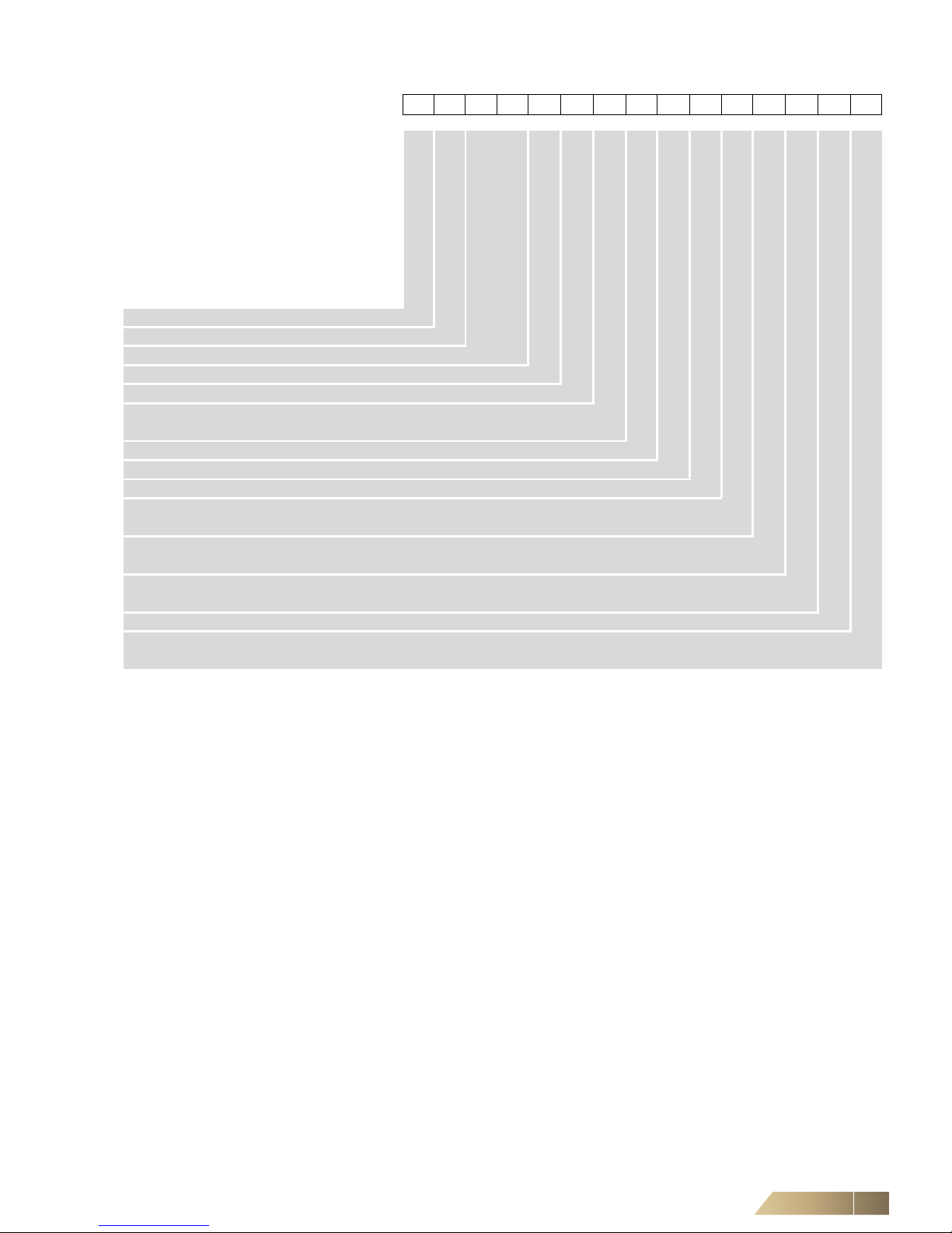
Refrigeration
Product
Range
Key Refrigeration
Refrigerant
Refrigerant circuit arrangement
Compressor size
Plate heat exchanger
Expansion valve
Liquid receiver
Shut off valve refrigerant
Connection type refrigeration
Refrigerant leakage detection
Compressor soft start
Service connections
D DENCO
M Multi-DENCO
RE Refrigeration
D R410A
1 Single circuit
N Small compressor
C Standard compressor
N Not fitted
E Electronic expansion valve
N Not fitted
S Shut off valves compressor and liquid line
L Shut off valve liquid line
S Solder connections
T Twin solder connections
L Refrigerant leakage detection
N Not fitted
N Not fitted
C Commissioning front connection points
N Not fitted
Multi-DENCO
6 FläktGroup DC-2013-0101-GB • Subject to modifications • R4-05/2018
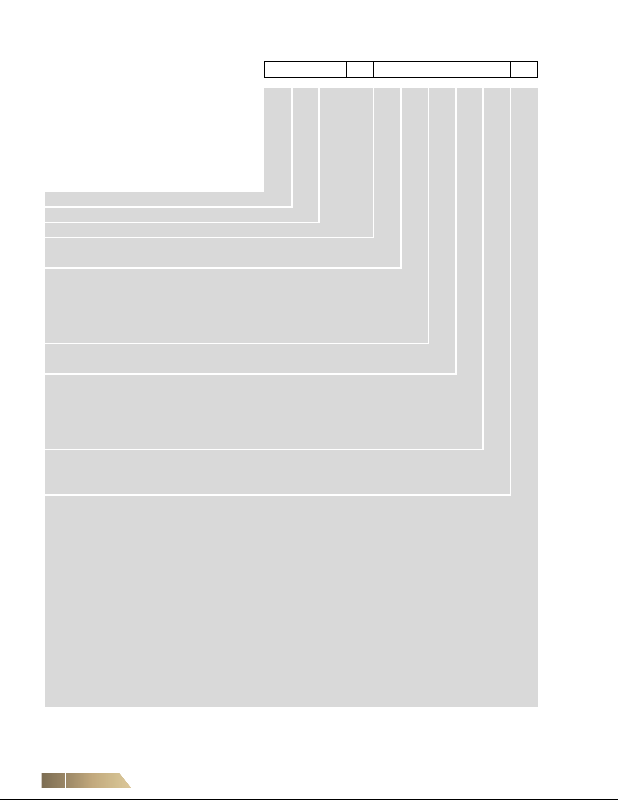
Water
Product
Range
Key Water
Shut off valve water
Connection type water
Water temperature monitoring
Valve type
Valve actuator
Valve kv
D Denco
M Multi-DENCO
WA Water
S Shut off valves chilled water
N Not fitted
B Threaded pipework connections (BSPT)
G Flange pipework connections PN06
F Flange pipework connections PN16
S Solder connections
N Not fitted
T Temperature monitoring probes
N Not fitted
2 2-way water valve
P 2-way water valve, pressure independent
3 3-way water valve with bypass
B 3-way water valve with bypass & regulating valve
N Not fitted
D DODC actuator
0 0-10 V actuator, drive open, spring return
N Not fitted
C kv = 1.0
D kv = 1.6
E kv = 2.5
F kv = 4.0
G kv = 6.3
H kv = 10
I kv = 16
J kv = 25
K kv = 40
L kv = 63
M kv = 100
X Small
Y Standard
N Not fitted
Multi-DENCO
FläktGroup DC-2013-0101-GB • Subject to modifications • R4-05/2018 7
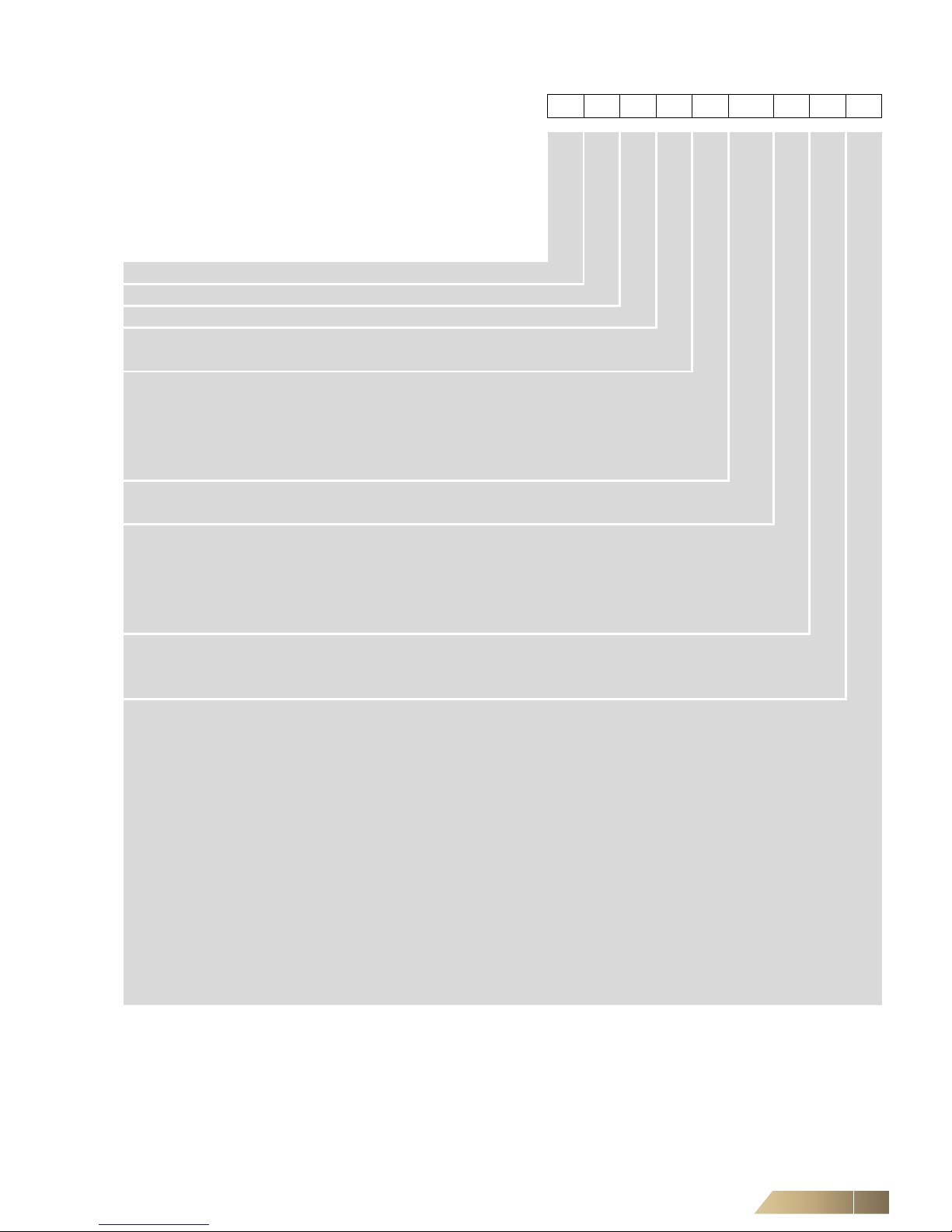
CombiCool
Product
Range
Key CombiCool
Shut off valve water
Connection type water
Water temperature
monitoring
Valve type
Valve actuator
Valve kv
D Denco
M Multi-DENCO
CC CombiCool
S Shut off valves chilled water
N Not fitted
B BSP pipework connections
G Flange pipework connections PN06
F Flange pipework connections PN16
S Solder connections
N Not fitted
T Temperature monitoring probes
N Not fitted
2 2-way water valve
P 2-way water valve, pressure independent
3 3-way water valve
B 3-way water valve with bypass & regulating valve
N Not fitted
D DODC actuator
0 0-10 V actuator, drive open, spring return
N Not fitted
C kv = 1.0
D kv = 1.6
E kv = 2.5
F kv = 4.0
G kv = 6.3
H kv = 10
I kv = 16
J kv = 25
K kv = 40
L kv = 63
M kv = 100
X Small
Y Standard
N Not fitted
Multi-DENCO
8 FläktGroup DC-2013-0101-GB • Subject to modifications • R4-05/2018
Controls
Product
Range
Key Controls
Controls
Interface BMS
Display
Run status
Water detection
Air sensor
Language
Fan speed
control indoor
Air volume flow
monitoring
Energy
monitoring
Pump signal
Ambient tempe-
rature control
Main switch
Smoke detection
Accessories
power supply
DENCO-Office-
Cool
Uninterrupted
power supply
D DENCO
M Multi-DENCO
CO Controls
C C5-12 controller
N Not fitted
L LonWorks interface
B BACnet MS/TP interface
E BACnet I/P, SNMP, Webpage interface
N Not fitted
T Touch screen display
N Not fitted
R Run status unit
N Not fitted
W Water detection, sensor tape and drain pan sensor
1 Water detection, 1 spot sensor and drain pan sensor
2 Water detection, 2 spot sensors and drain pan sensor
4 Water detection, 4 spot sensors and drain pan sensor
6 Water detection, 6 spot sensors and drain pan sensor
N Not fitted
1 Return Air T&H sensor
2 Return Air T&H sensor, 10 m cable
7 Return Air T&H + Supply Air Temp sensors
8 Return Air T&H + Supply Air T&H sensors, 10 m cable
9 Return Air T&H + Supply Air Temp sensors, 10 m cable
A Return Air T&H, 10 m cable + Supply Air Temp sensors
B Return Air T&H, 10 m cable + Supply Air T&H sensors, 10 m cable
N Not fitted
S Standard languages
O Other language (special)
N Not fitted
P Floor void air pressure control (APS)
S Fan speed control cooling demand
N Not fitted
V Air volume flow monitoring
N Not fitted
E Energy monitoring
N Not fitted
S Pump signal CombiCool free-cooling
N Not fitted
A Ambient temperature control CombiCool free-cooling
N Not fitted
M Main switch
D Dual power supply (ATS), inbuilt
S Smoke detection
N Not fitted
P Condensate pump
T Trend BMS interface
1 Condensate pump and Trend BMS interface
L LECU Interface
N Not fitted
U Uninterrupted power supply controls
N Not fitted
Multi-DENCO
FläktGroup DC-2013-0101-GB • Subject to modifications • R4-05/2018 9
Casing
Product
Range
Key Casing
Connection position
Display position
Unit colour
Filter gauge
Air grille unit top
Panel
Installation wheels
Packaging
D DENCO
M Multi-DENCO
CA Casing
B Pipework bottom entry
S Standard display position
L Lower display position
N Not fitted
R White
O Other unit colour (special)
G Filter differential pressure gauge
N Not fitted
1 Top air discharge protection grille (Eyelash)
2 Top air inlet protection grille (Eggcrate)
D Air damper
P Prepared for loose air damper
N Not fitted
S Standard panels
A Acoustic insulation panels
N Not fitted
S Standard packaging (Domestic)
E Wooden crate packaging (Export)
P Standard packaging (Domestic) with unit protection sheet
F Wooden crate packaging (Export) with unit protections sheets
Multi-DENCO
10 FläktGroup DC-2013-0101-GB • Subject to modifications • R4-05/2018
Outdoor Unit *
Product
Range
Key Outdoor unit
Outdoor system
Coolant
Unit size
Fan
Refrigerant cir-
cuit
arrangement
Compressor
size
Power supply
Winter kit
Heat exchanger
coating
Compressor
soft start
Unit colour
Packaging
Airflow direction
Number of
outdoor units
Deliver external
unit
Liquid receiver
Liquid receiver
size
D DENCO
M Multi-DENCO
OU Outdoor unit
C Condenser
D R410A
008 008
013 013
021 021
026 026
032 032
050 050
075 075
100 100
E EC fan
A AC fan with fan speed controller
F AC fan
1 Single circuit
N Not fitted
1 3~ 400 V, N, PE, 50 Hz
2 1~230 V, N, PE, 60 Hz
3 1~265 V, N, PE, 60 Hz
5 1~230 V, N, PE, 50 Hz
6 3~460 V, N, PE, 60 Hz
7 3~ 400 V, N, PE, 60 Hz
W Winter kit, -40 °C ambient
D Winter kit with double pressure relief valve, -40°C ambient
N Not fitted
B Blygold heat exchanger coating
E Epoxy heat exchanger coating
N Not fitted
N Not fitted
R Aluzinc
O Other unit colour (special)
S Standard packaging (Domestic)
E Wooden crate packaging (Ex-
port)
H Horizontal airflow
V Vertical airflow
1 1 outdoor unit
2 2 outdoor units
O External unit is included in package
N Deliver without external unit
P Liquid receiver with pressure relief valve
D Liquid receiver with double pressure relief valve
B Liquid receiver with pressure relief valve and pump-down
C Liquid receiver with double pressure relief valve and pump-down
N Not fitted
1 7L
2 12L
3 15L
4 18L
5 21L
6 25L
7 30L
8 36L
A 50L
N Not fitted
* A-Version, X-Version and H-Version
Multi-DENCO
FläktGroup DC-2013-0101-GB • Subject to modifications • R4-05/2018 11
Accessories
Product
Range
Key Ac-
cessories
Unit size
(indoor)
Accessory
D DENCO
M Multi-DENCO
AC Accessories
010 Size 010
018 Size 018
030 Size 030
045 Size 045
065 Size 065
092 Size 092
130 Size 130
BAS Base stand
PLI Plinth
PLIO Plinth, other colour (special)
TIL Raised floor tile support
PUM Condensate pump
PUH Condensate pump at humidifier
DAM Shut off damper
DAMC Shut off damper
TRA Underfloor unit drip tray
1WA Horizontal 1 way air discharge
1WAO Horizontal 1 way air discharge, other colour (special)
3WA Horizontal 3 way air discharge
3WAO Horizontal 3 way air discharge, other colour (special)
FI4 G4 Spare filter set
FI7 F7 Spare filter set
FI4C G4 Spare filter set
FI7C F7 Spare filter set
REM Remote monitoring touch screen display
TOU Touch up paint kit
D10 Ceiling connection duct 100 mm
D15 Ceiling connection duct 150 mm
D20 Ceiling connection duct 200 mm
D25 Ceiling connection duct 250 mm
D30 Ceiling connection duct 300 mm
D35 Ceiling connection duct 350 mm
D40 Ceiling connection duct 400 mm
D45 Ceiling connection duct 450 mm
D50 Ceiling connection duct 500 mm
D55 Ceiling connection duct 550 mm
D60 Ceiling connection duct 600 mm
D65 Ceiling connection duct 650 mm
D70 Ceiling connection duct 700 mm
D75 Ceiling connection duct 750 mm
D80 Ceiling connection duct 800 mm
D85 Ceiling connection duct 850 mm
D90 Ceiling connection duct 900 mm
D95 Ceiling connection duct 950 mm
D99 Ceiling connection duct 1000 mm
TRE Trend BMS interface
CEC Central Controller
PLV Plant Visor
TSD Top-side-down duct
Multi-DENCO
12 FläktGroup DC-2013-0101-GB • Subject to modifications • R4-05/2018
DENCO-OfficeCool
Product
Range
Cooling system
Unit size
Air routing
Panel configuration
Heat exchanger
Compressor control
Humidifier
Filter
Fan
Heating
Power supply
D Denco
M Multi-DENCO
O Chilled water OfficeCool
H Split System OfficeCool
010 Size 010
018 Size 018
030 Size 030
045 Size 045
D Downflow
U Upflow
P Front full height panel
S Standard heat exchanger
H Heat pump heat exchanger
N Not fitted
S Steam humidifier standard conductivity
L Steam humidifier low conductivity
H Steam humidifier high conductivity
N Not fitted
4 Filter G4
7 Filter F7
W Filter washable G4
P EC plug fan
N Not fitted
1 3~400 V, N, PE, 50 Hz
6 3~460 V, N, PE, 60 Hz
Multi-DENCO Overview of Units and Scope of Supply
FläktGroup DC-2013-0101-GB • Subject to modifications • R4-05/2018 13
1 Overview of Units and Scope of Supply
1.1 Introduction
We would like to thank you for purchasing our products.
Multi-DENCO units are intended and designed for indoor installation for cooling, hea-
ting, humidification, dehumidification and filtering of air at atmospheric pressure. The
units are designed as refrigeration systems and/or chilled water systems and it is prohibited to use our units for any other purposes. The equipment has been designed and
manufactured within a 'Quality Assurance System' within a strict quality controlle d environment to ensure that it reaches you in perfect condition.
For help, assistance, spares or your local office, please visit the following website for
contact details in your region:
https://www.flaktgroup.com/en/contact-us/
1.2 Model number explained
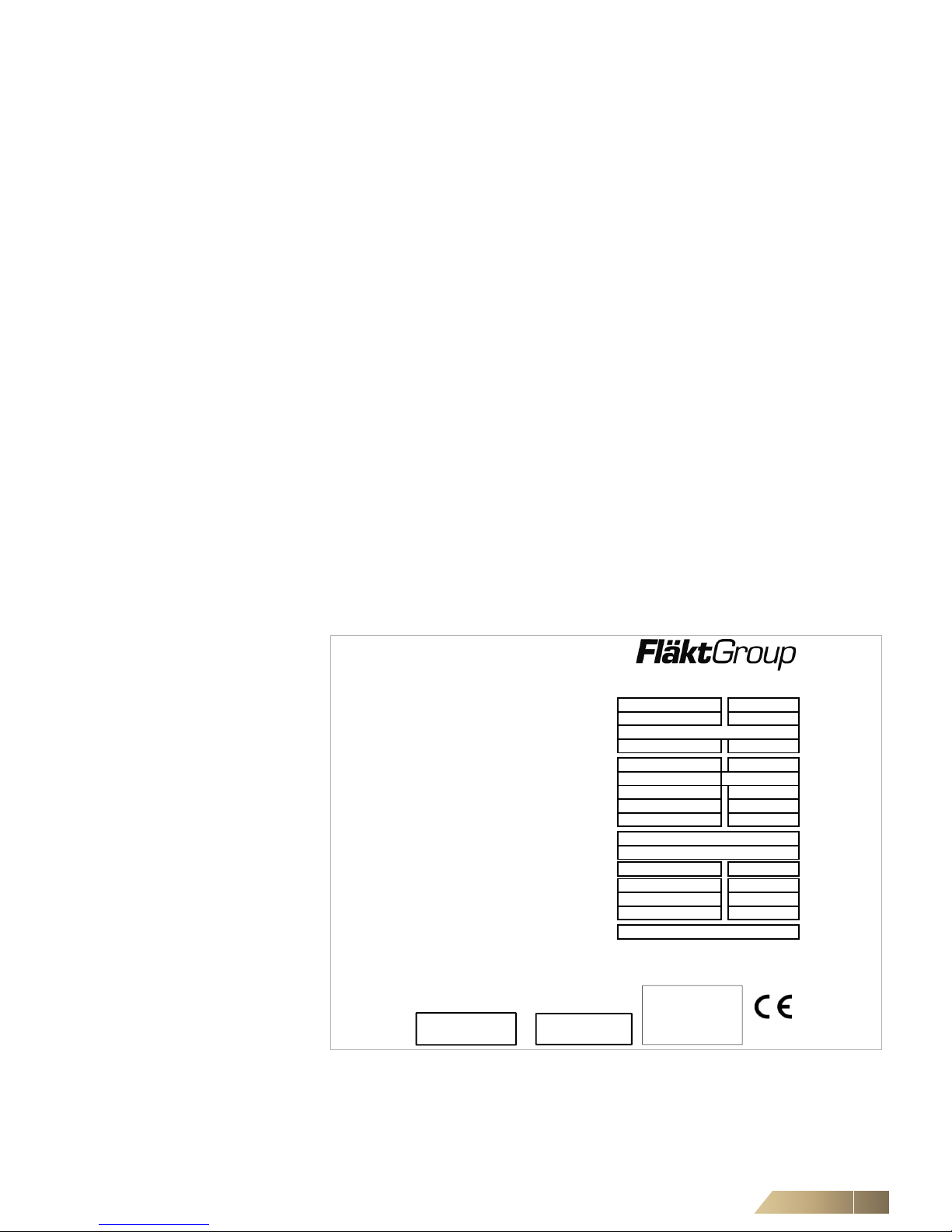
Each product carries an 'Identification Plate' (sometimes referred to as 'serial plate')
inside the equipment for indoor units. For outdoor units, this maybe be on the external
casing. This identification plate carries information that is important and unique to the
unit.
Upon receipt of your equipment it is important to check the 'MODEL NUMBER' (a shortened version called 'Model Type Code' is shown on the seria l plate) prior to positioning
and installation, to ensure it matches your requir ements. Any discrepancie s should be
reported immediately to your representative.
Refer to page 4 for the type code of a particular unit. Below shows an example serial
plate for a Multi-DENCO A-Version unit.
PRODUCT RANGE / PROJECT TYPE
Multi-DENCO® STANDARD
MODEL TYPE CODE / PED
DMA030DPSIN4PN1 CAT. 1
SERIAL NUMBER
CONTRACT NO. / DATE OF BUILD
110196 02 / 2017
OPERATION MAN. / WIRING DIAGRAM
PR-2013-0101 110196-101
VOLTAGE / PROTECTION RATING
400V-3PH-50HZ/60HZ+N
IP20
MAX. PRE-FUSE
32 TYPE D
FULL LOAD INPUT
11,4 kW
FULL LOAD CURRENT
29,9 A
COOLING MEDIUM
SOFTWARE VERSION
MWP HIGH PRESSURE SIDE
4,32 MPa
MWP LOW PRESSURE SIDE
4,32 MPa
CHILLED WATER
0,70 MPa
EMPTY WEIGHT
330,00 Kg
NOTE
6WC955
CV3.04.009B/DV4.06.009B
R410A (GWP 2088) & WATER
FIELD CHARGE (kg)
CO2e
1015
FläktGroup Czech Republic a.s.
Slovanská 781, 463 12 Liberec XXV - Vesec, Czech Republic
ANY MODIFICATION MAY NOT BE REFLECTED ABOVE
=
( Field Charge (R410A) / 1000 ) x 2088 = CO2e
CONTAINS
GREENHOUSE
FLUORINATED
GASES
Overview of Units and Scope of Supply Multi-DENCO
14 FläktGroup DC-2013-0101-GB • Subject to modifications • R4-05/2018
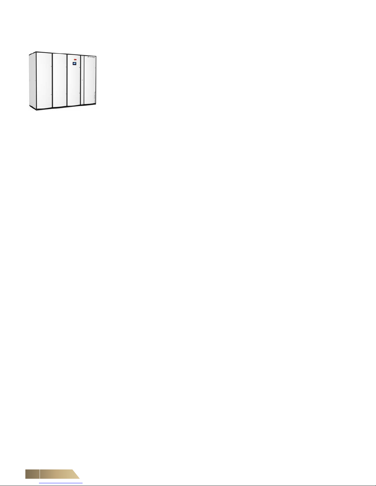
1.3 Product series overview
There are 3 versions of the Multi-DENCO product: A-Version, C-Version and X-Version. These versions have some common elements and also individual chara cteristics.
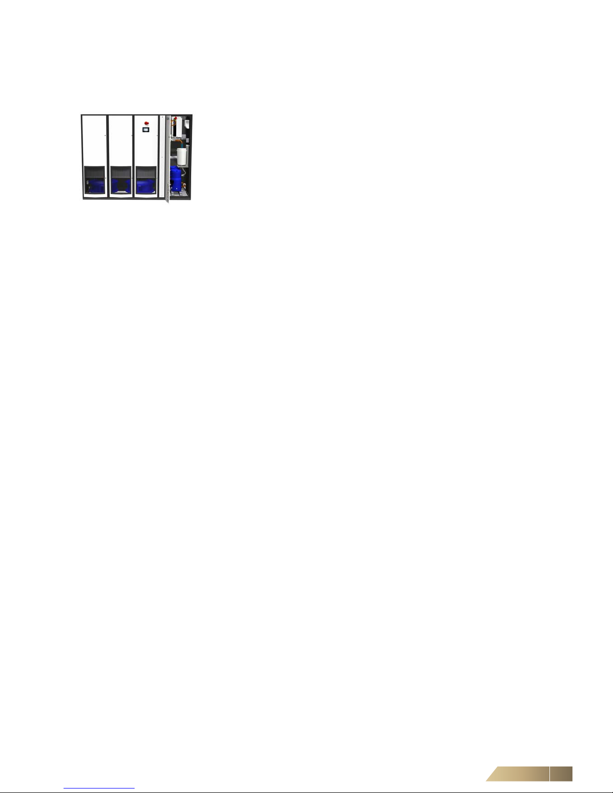
Fig. 1-1: A Multi-DENCO Unit
Common features &
options
– 7 standard box sizes (010, 018, 030, 045, 065, 092 and 130)
– Cooling capacities up to 150 kW
– Available with both upflow or downflow air paths
– Large EC plug fans
– Integrated or remote temperature and humidity sensors
– Large surface area for heat exchanger coil
– Available with full panel doors or with grilles within the doors
– Humidification and heating options available
– Standard control software and hardware that is compatible for all versions
– Building Management System (BMS) interface compatible
A-Version – Refrigeration based cooling
– R410A used as standard
– Inverter compressors as standard (fitted in indoor unit)
– Electronic expansion valve as standard (fitted in indoor unit)
– Typically supplied with an outdoor condenser
C-Version – Water based cooling
– Can operate with Glycol
– A method of heat rejection separate to Multi-DENCO unit (e.g. Chiller)
– Can be provided with 3-way, 2-way or 2-way PICV valves and a variety of actuators
X-Version – Refrigeration based cooling
– R410A used as standard
– Available for sizes 010 to 045
– Inverter compressors as standard (fitted in outdoor unit)
– Electronic expansion valve as standard (fitted in outdoor unit)
– Typically supplied with an outdoor condensing unit
CombiCool Coil (Optional) A and C-Version units can be upgraded to have inbuilt redundancy. A unit with a Com-
biCool coil, consists of a primary and a secondary circuit. The primary circuit will be a
chilled water cooling circuit. When parameters leave the allowable boundaries (e.g.
chilled water inlet temperatures are too high) then the primary circuit will stop and the
secondary circuit will be activated (e.g. the A-Version DX circuit) to continue the cooling process. A CombiCool coil can also be used in a FreeCool strategy.

Multi-DENCO Overview of Units and Scope of Supply
FläktGroup DC-2013-0101-GB • Subject to modifications • R4-05/2018 15
1.4 DENCO-OfficeCool
DENCO-OfficeCool is a separate version of the Multi-DENCO design and custommade for use in an office environment or similar requiring comfort cooling. The units
consist of one Zone unit to many Local Environmental Control Units (LECUs) to give
temperature control through a raised floor.
Typically, DENCO-OfficeCool units are in downflow air configuration, but Upflow units
can be used with a 'top side down duct'. This can be referred to as 'Underfloor Air Conditioning'.
O-Version – Water based cooling
– Can operate with Glycol
– A method of heat rejection separate to Multi-DENCO unit (e.g. Chiller)
– Can be provided with 3-way or 2-way valves and a variety of actuators
– Available for sizes 010 to 045
– Acoustic insulation and slower fan speeds
H-Version – R410A used as standard
– Available for sizes 010 to 045
– Inverter compressors as standard (fitted in outdoor unit)
– Acoustic insulation and slower fan speeds
– Heat pump options available
1.5 Scope of supply
A typical order of a Multi-DENCO unit could consist of (but is not limited to):
– Indoor unit of Multi-DENCO configuration with associated internal options pre-
installed (unless requiring placement external to the unit or further installation, in
which case, hardware is provided loose within the unit)
– Outdoor unit (Optional) a condenser, condensing unit or drycooler to act as a heat
rejection unit for the system
– Unit documentation
– A copy of the current operation manual (indoor and/or outdoor)
– Controller manual
– Wiring diagrams for both indoor and outdoor units
– Dimensional drawing
– Spare part list in the form of a label or a printed sheet
– Accessories (optional) Any other accessories that may be required for the indoor
or outdoor unit, for example; plinths, base stands, ceiling return sections etc. may
be provided in separate packaging
1.6 Accessories and special equipment
Multi-DENCO units can be designed with a vast number of accessories and features.
To determine the scope of options fitted to your unit, compare the supplied unit 'Model
Number' with the unit model number specified in the typecode.
1.7 Directives and regulations
We certify that products supplied within the range of Multi-DENCO conform to, meet
and/or exceed the requirements of the following directives and regulations:
– Directive on Machinery 2006/42/EC
– Low Voltage Directive 2014/35/EU
– Electromagnetic Compatibility (EMC) 2014/30/EU
– Pressure Equipment Directive 2014/68/EU

Overview of Units and Scope of Supply Multi-DENCO
16 FläktGroup DC-2013-0101-GB • Subject to modifications • R4-05/2018
1.8 References within manual
The following references to standards and regulations are made within this manual.
These may be updated or revised by the relevant bodies, after publication of this
manual. In all instances, review the latest versions for any relevant updates.
(EC) No. 842/2006
EN 378
DIN EN ISO 3745
2014/68/EU
2006/42/EC
2014/30/EU
2014/35/EU
EN 12735-1:2010
EN 60204-1:2006+A1:2012
(EU) No. 517/2014
2008/98/EC
2012/19/EU

Multi-DENCO Safety and User Information
FläktGroup DC-2013-0101-GB • Subject to modifications • R4-05/2018 17
2 Safety and User Information
The Multi-DENCO range is designed in accordance with state-of-the-art technological
and engineering standards as well as in conformity with the recognized safety regulations.
It must be used in an appropriate manner for suitab le pu rp o ses , follo win g th e de ta ils
contained within this manual and taking account of safety aspects and potential
hazards.
Failure to follow the instructions in this manual may result in danger to health and
safety, damage to materials and incorrect unit operation. Information within this
document advises on, but is not limited to, potential threats or concerns related to
health and safety. All users must be, or employ, a trained professional to, assess
issues relating to health and safety, before any handling the Multi-DENCO unit.
2.1 Availability of the operation manual
This operation manual contains important information regarding safe and correct operation of the unit.
This manual must always be available at the site where unit is operating. Every person
working on the equipment must read this manual fully before commencing the work
and take note of all relevant information while performing a task.
The operation manual is intended to be used by fitting and installation companies, building services engineers, technical personnel or trained persons as well as electrical
and refrigeration engineering specialists.
2.2 Scope of the operation manual
THIS IS AN ORIGINAL OPERATION MANUAL VERIFIED BY THE MANUFACTURER.
This document has been developed by the manufacturer specifica lly for details relating
to the Multi-DENCO range. Information within this document may be common to other
designs or products, but the information contained is exclusiv e to Multi-DENCO and
non-transferable. The information should not be used as a basis for any other products.
Every effort is made to ensure that informat ion contained within this m anual is fair and
accurate, but FläktGroup endeavours to continuously update and improve all of our
products for our customers. Due to this continuous development, some information
contained within this manual may become outdated or no longer releva nt. If you are in
any doubt regarding any information contained within this document, please contact
your local sales or support representative who will be happy to assist and enquire
further for you.

Safety and User Information Multi-DENCO
18 FläktGroup DC-2013-0101-GB • Subject to modifications • R4-05/2018
This operation manual covers topics in the following areas:
– Safety and User Information
– Technical Descriptions
– Shipping and Storage
– Installation
– Mechanical and Electrical Connections
– Commissioning
– Operation
– Servicing and Maintenance
– Troubleshooting
– Disassembly
2.3 Document format
Significant information for each chapter will be highlighted in the following format:
– This symbol is used to indicate normal lists.
• This symbol indicates instructions to follow.
9 The result of an action is indicated with this symbol.
NOTE!
Please refer to Controls Operation Manual for details about software and control
operation of your Multi-DENCO!
NOTE!
This manual is valid only for configurations built from our standard catalogue.
Any units designed or supplied under special configurations ( sometimes referred to
as 'Engineering Specials'), may not be covered by previous, existing or future
documentation.
Please refer to your sales/support contact for any information regarding special
designs.
NOTE!
Here you will find additional details on using the Multi-DENCO unit.
Multi-DENCO Safety and User Information
FläktGroup DC-2013-0101-GB • Subject to modifications • R4-05/2018 19
2.4 Signs used within this manual
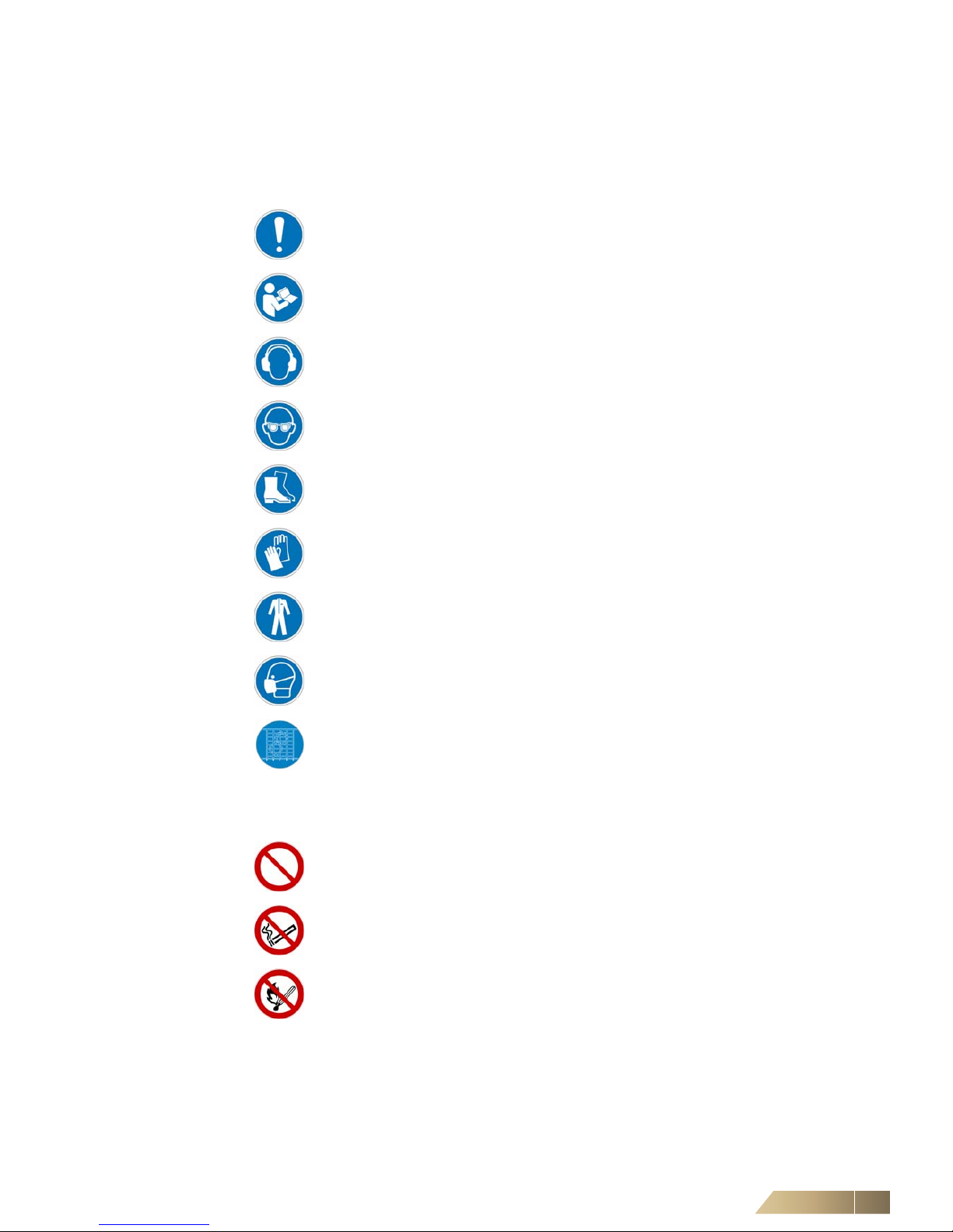
2.4.1 Mandatory Signs
2.4.2 Prohibition Signs
General Mandatory Sign
Refer to manual or documentation
Wear ear protection
Wear eye protection
Wear safety footwear
Wear protective gloves
Wear protective clothing
Wear a protective mask
Guards must be used during operation
General prohibition sign
No smoking
No open flame, fire, open ignition source
Safety and User Information Multi-DENCO
20 FläktGroup DC-2013-0101-GB • Subject to modifications • R4-05/2018
2.4.3 Warning Signs
General warning sign
Warning of low temperature
Warning of electricity
v
Warning of suspended loads
Warning of toxic substances
Warning of hot surfaces
Warning of automatic starting machinery
Warning of sharp elements
Warning of crushing to limbs
Possible damage to machinery
Environmental damage
Multi-DENCO Safety and User Information
FläktGroup DC-2013-0101-GB • Subject to modifications • R4-05/2018 21
2.5 Labelling of safety information
The following symbols and notices are provided in appropriate plac es thro ugh out th is
document to designate the safety instructions:
2.5.1 DANGER – Death/serious irreversible injury
Indicates an extremely hazardous situation which will result in death or serious irreversible injury, if the safety instruction is not followed.
Example:
2.5.2 WARNING – Death/serious injury
Indicates a hazardous situation which can result in death or serious irreversible
injury, if the safety instruction is not followed.
Example
:
Electrocution through hazardous voltage will lead to death or serious injury!
• Disconnect all electric power and ensure the power cannot be inadvertently
energized.
• Verify that all circuits are deenergized, earth, short-circuit and block off all
neighbouring live parts.
High concentration of refrigerants in the air can result in death or serious injury!
High concentration of refrigerants in the air may have an anaesthetic effect and
cause unconsciousness. Prolonged exposure may cause irregular heartbeat and
sudden death. Very high concentration of refrigerant may cause suffocation by
reduced oxygen content in the surrounding air.
• You should therefore only work in an adequately ventilated environment, and
exercise due care and attention when carrying out the work.
• Wear protective clothing and, if necessary, an autonomous breathing apparatus.
Safety and User Information Multi-DENCO
22 FläktGroup DC-2013-0101-GB • Subject to modifications • R4-05/2018
2.5.3 CAUTION – Minor or moderate injury
Indicates a hazardous situation which can result in minor or moderate injury, if the
safety instruction is not followed.
Example:
2.5.4 NOTICE – Environmental or material damage
Indicates actions that can result in equipment or property-damage only accidents.
Examples:
Injury due to sharp cutting edges!
• While cleaning care should be taken to prevent risk of injury due to thin fins.
• Wear protective gloves
NOTICE
NOTICE
Environmental Damage!
• Dispose of all components and materials (such as water-glycol mix) depending
on material type in an environmentally friendly manner and in accordance with
the local codes, practices and environmental regu latio n s.
NOTICE
Damage to the unit!
• Do not mix up cables during connecting.
• Use the unit wiring diagram to check electrical cablings.
Multi-DENCO Safety and User Information
FläktGroup DC-2013-0101-GB • Subject to modifications • R4-05/2018 23
2.6 Safety-conscious working
The following is initial general advice to consider during various stages of a project.
More specific information can be found in relevant chapters in this manual.
2.6.1 At all times
To comply with EN 378-3 you must wear suitable Personal Protective Equipment
(PPE) at any point working on a Multi-DENCO unit. As a minimum we recommend:
• Wear safety footwear
• Wear eye protection
• Wear protective gloves
• Wear protective clothing
If operating for a prolonged period of time , noise reducing ear protection may be required.
• Always condu c t your ow n pe rs on a l risk assessment to evaluate any further
requirements.
2.6.2 During installation & commissioning
At these times there are higher risks involved with the handling and operating around
a Multi-DENCO system. Further information is provided in chapters 4 to 8.
• Always refer to the latest operation manual and support technical documents
provided with the unit.
• Do not make assumptions based on other products design or information.
• If in doubt, contact your local sales office.
• Protect against unauthorised access.
• Do not use or employ un-qualified or inexperienced workers to install or commission
the Multi-DENCO system.
Filters (especially used or dirty filters) are easily flammable. Leaking refrigerant can
catch fire and emit noxious substances.
– No smoking is allowed in direct proximity of any aspect of the
Multi-DENCO system.
– No open flames near the system.
During installation there is a higher chance of leaks of refrigerant or glycols.
Before adding any cooling medium, ensure:
– Any system pipework is thoroughly tested for leaks
– Use non-polluting methods for testing purposes, e.g. Oxygen Free Nitrogen (OFN)

Safety and User Information Multi-DENCO
24 FläktGroup DC-2013-0101-GB • Subject to modifications • R4-05/2018
2.6.3 When unit is operational
Information regarding 'Fan touch protection' can be found in Chapter 5.7.
Further relevant information is provided in chapters 9 to 11.
2.6.4 R410A systems
EN 378:2008 Part 1 defines R410A refrigerant to group A1. When using refrigerant
consider your usage in accordance to Regulation (EC) No 842/2006.
Features of R410A:
– Non-combustible
– No direct toxic effect
– Colourless and odourless
– Heavier/denser than air
– Contains fluorinated greenhouse gases as defined by the Kyoto Protocol
– Ozone-depleting potential OPD: 0
– Greenhouse potential GWP: 1980
– Water hazard class WGK: 1, with a slight risk to water
At any time the unit is operational, rotating machinery and electrically charged components are present. When the unit is not electrically isolated:
• Ensure all guards and doors are closed.
• Only remove guards or open doors:
– When the unit has been electrically isolated.
– Sufficient time has been allowed for the rotating fan momentum to cease.
– Sufficient time has been allowed for inverter circuits to discharge.
NOTE!
Refer to 'Field Charge' on the unit serial plate (see chapter 1.2) in r egards to system
refrigerant volume.
NOTICE
• Always refer to the Material Safety Data Sheet (MSDS) from the supplier.
– Information relating to hazards, handling and storage, first aid amongst other
information is contained within the MSDS.
• Store these document(s) along with the Multi-DENCO documents.
Due to the nature of a refrigeration circuit, a Multi-DENCO system can co ntain dangerously hot and dangerous cold aspects within the same system or circuit. Failure
to wear PPE could result in moderate injury.
• Review the appropriate chapters for further information.
• Never touch any part of the refrigeration circuit with unprotected skin.
• Always conduct your own personal risk assessment to evaluate any further
requirements.

Multi-DENCO Safety and User Information
FläktGroup DC-2013-0101-GB • Subject to modifications • R4-05/2018 25
2.6.5 Systems containing glycol
General features of glycols:
– Usually mixed with water.
– Can reduce the freezing temperature point of the mixture.
– Reduces cooling capacity when compared to water-only systems.
Further information can be found in Chapter 6 and Chapter 8 of this manual.
2.7 Proper use
The Multi-DENCO series are designed as indoor units and for connection to a heat
rejection system. They are designed for cooling, heating, humidification, dehumidification and filtering of air at atmospheric pressure.
Unless otherwise stated the equipment will not be suitable for use in corrosive atmospheres, for example, areas near large volumes of salt water.
Proper use also requires adherence to the operation manual for the controller and
suitable and regular inspection and maintenance, following guidelines specified by
FläktGroup.
Improper use Any use other than that described above is considered improper. The manufacturer/
supplier is not liable for damage arising from improper use. The user alone bears any
risk or cost that can be attributed to 'improper use'.
It is not allowed to operate units:
– in explosion risk areas;
– in areas with strong electromagnetic fields, (electromagnetic immunity as of EMC
Directive; refer to the Declaration of Conformity in the unit documentation)
– in environment with high levels of air contamination,
– in environments with corrosive and/or aggressive air.
2.8 Modifications and changes
Changes or modifications of any Multi-DENCO units after dispatch from factory shall
only be performed following discussion and approval by the sales office. Any works
planned that are not covered in this manual must be discussed with, and are subject
to approval; non compliance could invalidate the CE conformity and may void the warranty.
2.9 Spare parts
Only original spare parts from our spare parts department are allowed. Use of third
party spare parts are not allowed and are at the user's own risks. A common spare
parts list is enclosed with the unit (either printed or in the form of a sticker). If in any
doubt as to the spare part required, please contact your local sales representa tive who
will be able to assist.
NOTICE
Properties of different glycols can vary significantly between different types of glycols
and different manufacturers
• Always refer to manufacturer’s information for usage guidelines
• Always handle and dispose in accordance with local codes, practices and
environmental regulations.

Safety and User Information Multi-DENCO
26 FläktGroup DC-2013-0101-GB • Subject to modifications • R4-05/2018
2.10 Disposal
Main and operating supply materials shall be disposed of according to material type in
a safe and environmentally friendly manner – always refer to your local by-laws and
Country specific legislation (also refer to section 12.2 Disposal).
2.11 Personnel selection and qualification
• Any individual working on the unit must read and understand all of this manual
before starting any works.
• Any individual working on this system shall be suitably qualified and licensed for the
region that the system in installed within.
• Within the European Union, refrigeration circuit operators shall be in accordance
with (EC) No 842/2006 Articles 4 & 5.
• All personnel involved with the system must understand and observe any local
legislation regarding safe working practice.
2.12 Noise
The sound power level of the unit can rise up to 98 dB(A) according EN ISO 3745
accuracy class 1.
2.13 Environmental considerations
Some Multi-DENCO versions can use refrigerants, therefore careful and specific attention is required regarding the handling and storage. Consideration must be given to
minimise or eliminate any discharge of refrigerant (accidental or deliberate). Chilled
water as a cooling medium may contain impurities or chemicals (such a s glycol) requiring disposal according to local or regional codes, practices and environmental regu lations.
FläktGroup highly advises that at all stages of our product lifestyle (purchase, install,
maintenance and disposal) carefully consideration is given to any decision to ensure
minimal environmental impact.
Further information about our policies and values can be found on our website:
www.flaktgroup.com
Multi-DENCO Technical Description
FläktGroup DC-2013-0101-GB • Subject to modifications • R4-05/2018 27
3 Technical Description
3.1 Unit description
Multi-DENCO units are designed for indoor installation (no exposure to outdoor
weather) and the system is completed by being connected to an heat rejection system
(for example; condenser, drycooler, chiller etc). Typically the units are designed for
cooling data centres, though they have a large var iety of uses, such as (but not lim ited
to): server rooms, telecom rooms, laboratories, museums, libraries, production environments etc.
Heat exchange and airflow is performed vertically; with downflow models receiving
warm air from the top of the unit and delivering cold air at the bo ttom and upflow units
taking warm air from the bottom of the unit and discharging cold air at the top. These
airflows can be directed at entry and exit of the unit, by using accessories such a s: front
door grille, ceiling return section, base stands, horizontal discharge sections and dampers.
Multi-DENCO units are available in 7 sizes ranging from (WxDxH) 600x600x1940mm
to 3380x880x1968 mm. These units come with a wide vari ety of acce ssories a nd options meaning that each Multi-DENCO unit can be tailored to your room's needs.
Once you have received your Multi-DENCO unit, typical onsite tasks include, (but are
not limited to):
– Installation and positioning of units
– Refrigeration/pipework connections between indoor and outdoor unit
– Connection of electrical power supply
– Connection of communication cabling
– Installation of any accessories provide 'loose' (e.g. water detection tape)
– Commissioning of the Multi-DENCO unit
– Configuration of network settings
3.1.1 DENCO-OfficeCool
This is a variation of a Multi-DENCO unit designed specifically to address the needs of
comfort cooling. The design is aimed at reducing fan velocities, reduced sound and
features for integration with Local Environment Control Units (LECUs) allowing for
adjustable environment to suit comfort levels. These are available as dir ect expansion
or chilled water versions.
DENCO-OfficeCool design are mostly similar to the requirements and design of
Multi-DENCO units. Within this manual, any differences in the design will be explained.
Fig. 3-1: Multi-DENCO Unit,
A-Version, Size 092
Technical Description Multi-DENCO
28 FläktGroup DC-2013-0101-GB • Subject to modifications • R4-05/2018
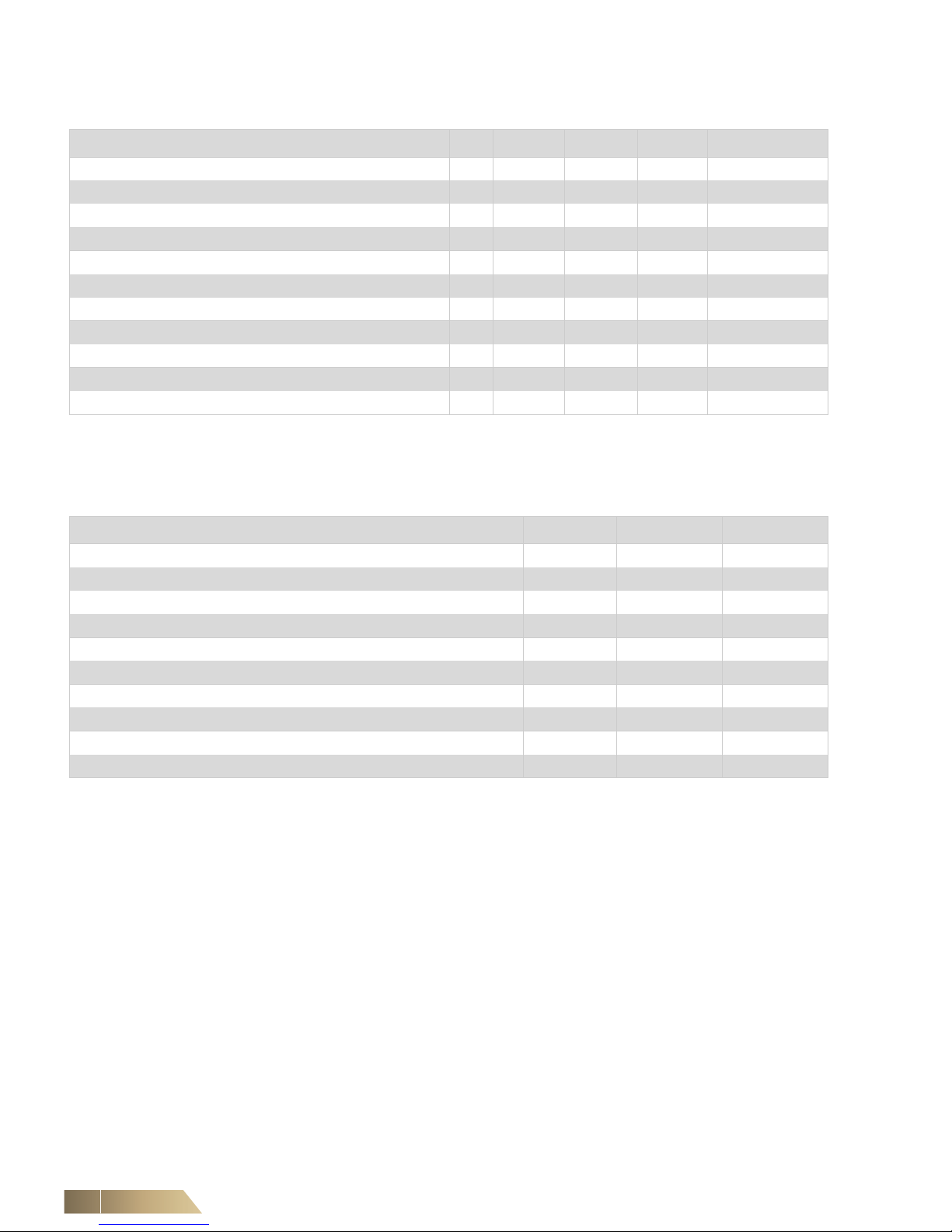
3.2 Operating limits
3.3 Operating modes
A basic Multi-DENCO unit only has the capacity to perform cooling, therefore only
being able to control the upper limit of the temperature o f the room. Heaters and humidifiers can be added to the design to allow for control of both the lower limit of temperature and to control the humidification of the room.
Cooling The main function of a close control unit is to cool the air within a room to a defined set
point.
If using refrigerant (A-Version & X-Version), this is achieved by adjusting compressor
speed, expansion valve opening and indoor and outdoor fan speed.
If using chilled water (C-Version), this is accomplished by adjusting the water valve
opening and adjusting the indoor fan speed.
Both methods use variable technology to match the heat of rejection by the
Multi-DENCO unit to the volume of heat produced within the room.
Multi-DENCO Unit A-Version C-Version X-Version CombiCool Circuit
Indoor Temperature Minimum °C 10 10 10 10
Indoor Temperature Maximum °C 40 40 32 40
Indoor Humidity (Absolute) Minimum g/kg 2 2 2 2
Indoor Humidity (Absolute) Maximum g/kg 18 18 18 18
Outdoor Ambient Air Temperature Minimum (Standard) °C -20 N/A -15 N/A
Outdoor Ambient Air Temperature Minimum (with low ambient kit) °C -40 N/A N/A N/A
Outdoor Ambient Air Temperature Maximum °C 55 N/A 46 N/A
Condensing Temperature Minimum °C 35 N/A 35 N/A
Condensing Temperature Maximum °C 64 N/A 64 N/A
Maximum Operating Pressure (High) MPa 4.32 0.6
2
4.15 0.6
2
Maximum Operating Pressure (Low) MPa 4.32/3.00
1
N/A 4.15 N/A
1
4.32 MPa for unit sizes 010 to 065. 3.00 MPa for unit sizes 092 & 130
2
Default configuration for standard design. 1.00MPa for certain configurations
DENCO-OfficeCool Unit H-Version O-Version
Indoor Temperature Minimum °C 10 10
Indoor Temperature Maximum °C 32 40
Indoor Humidity (Absolute) Minimum g/kg 2 2
Indoor Humidity (Absolute) Maximum g/kg 18 18
Outdoor Ambient Air Temperature Minimum °C -15 N/A
Outdoor Ambient Air Temperature Maximum °C 46 N/A
Condensing Temperature Minimum °C 35 N/A
Condensing Temperature Maximum °C 64 N/A
Maximum Operating Pressure (High) MPa 4.15 0.6
1
Maximum Operating Pressure (Low) MPa 4.15 N/A
1
Default configuration for standard design. 1.00MPa for certain configurations

Multi-DENCO Technical Description
FläktGroup DC-2013-0101-GB • Subject to modifications • R4-05/2018 29
Heating (if fitted) If the indoor temperatures are too low then the heating function will be activated. There
are several options for this operation allowing the heating to be a start/stop operation
or variable. When heating is required, the fans can increase their speed.
Humidification (if fitted) If the humidity levels are below the requirements then the humidifier will be activated
to add more moisture to the air. The amount of moisture added to th e air varies proportionally to the demand, with the humidifier able to operate between 25 - 100% of its
rated capacity.
Dehumidification (if enabled) As a default factory settings, dehumidification is a secondary priority compared to tem-
perature control, therefore it will only become active and maintained if the temperature
limits are met during the whole operation. If at any point, those limits are not met, the
dehumidification operation will be stopped and the unit will operate on a temperature
control basis.
To perform dehumidification, the unit cools at a higher rate (i.e. over-cools the air) to
create condensate on the the heat exchanger coil. Heating options can then be used
to re-heat the air before it leaves the unit.
Software settings can be changed to deactivate the dehumidification modes, even if
components are fitted.
CombiCool (if fitted) The CombiCool options has two separate cooling circuits. CombiCool can be fitted to
A- & C-versions of the Multi-DENCO units.
The CombiCool circuit is the primary circuit and is chilled water. The secondary circuit
relates to the version (e.g. A-Version, C-Version). The unit will only operate one circuit
at a time.
If the CombiCool circuit is unable to meet the cooling requirements of the room then
the unit changes to use the 'secondary' circuit. When possible, the unit will try to switch
back to the 'primary' CombiCool circuit.
This feature is ideal to provide internal redundancy to each unit.
CombiCool FreeCool
(if fitted)
The unit is fitted with the same CombiCool Coil as above, but can be configured with a
FreeCool strategy. When the Cooling Demand is low, the unit will operate with only the
FreeCool circuit operating. If this demand increases above a certain threshold, the unit
will then activate its secondary circuit (direct expansion or chilled water) and both circuits to operate at the same time to meet the cooling requirements.
An ambient sensor can be used to measure the outdoor temperatures. If the ambient
temperature is high (above a set value), then the FreeCool circuit will be deactivated
and only the secondary circuit will operate. Once the ambient temperature has reduced
then the FreeCool circuit will become available again.
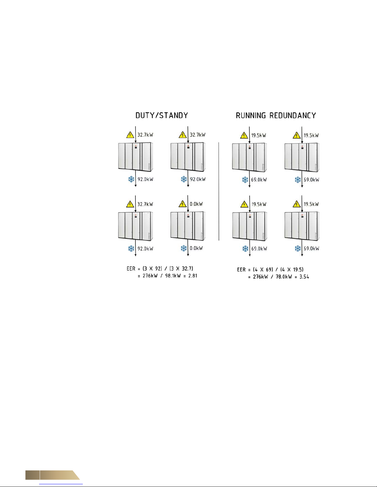
3.4 Operating strategies
Multi-DENCO's inbuilt advance software combined with the latest EC variable technology and networking capability, enables the unit to operate with intelligent control strategies to increase performance or maximise energy savings. In most instances we
would recommend using a Running Redundancy strateg y to help maximise the energy
savings possible.
Duty/standby operation Within a room there may be additional units installed as a backup to maintain cooling
performance in case there is an alarm or failure on a unit. A comm on description is an
'N+1' setup, where N describes the number of units require d to co ol a room. By u sing
the network capability of the unit, upon failure, a signal can be sent to start the standby
unit.
The network of units can be configured so that the unit designated as 'standby' is changed over after a pre-set period to ensure even wear over their lifetimes.
Technical Description Multi-DENCO
30 FläktGroup DC-2013-0101-GB • Subject to modifications • R4-05/2018
Running redundancy Instead of the standby unit(s) remaining off, running redundancy allows all units to ope-
rate at the same time, reducing their cooling requirements. This is can be referred to
as 'Hot/Cold Standby'.
Each unit will operate on 'part load', reducing the speed of the fans and other variable
components. The network would still have backup capability: if a unit developed a fault
the other units would use their spare capacity to meet the cooling requirements.
By operating in part load, there are significant energy savings when compared to a traditional 'Duty/Standby' operation. The diagram shows an example of savings available:
Fig. 3-2: Running Redundancy Example
Sensor averaging Sensor averaging can be calculated on temperature, humidity or both, when
Multi-DENCO units are connected in a network. Each unit sends their sensor readings
to every unit in the network. Each unit then takes all the values and calculates the average independent of the network units.
This gives the advantage of balancing the cooling re quirements a cross all of th e un its
within a room, rather than on individual airflows. The software has features to allow for
sensor, communication or unit failure, so that the values do no distort the average
value and the unit can change back to 'stand-alone' if necessary.
Automatic Pressurisation
System (APS)
APS ensures a constant pressure in the floor plenum by the Multi-DENCO unit. This
can help reduce hot spots and allows for fast reaction to changes in airflow.
This also saves energy as the Multi-DENCO fans only supply the same amount of air
to the floor void, as the amount of air being removed by servers.
For datacentres, this feature can be especially efficient when combined with cold-aisle
containment.
 Loading...