

FläktGroup MINIMASTER RDKS Installation, Operation, Maintenance And Spare Parts
HEAT RECOVERY UNIT
MINIMASTER RDKS
INSTALLATION, OPERATION, MAINTENANCE AND SPARE PARTS

2
CONTENTS
OPERATION AND MAINTENANCE (FOR USER)
Functions, system design, electrical data, energy class ............................................... 3
ISYteq Basic control panel
Operation .................................................................................................................................... 4
Overview of symbols and functions ................................................................................ 5
ISYteq Touch 3.5 control panel .....................................................................................................
General information ................................................................................................................6
Cleaning of the display .........................................................................................................6
General buttons and symbols ............................................................................................6
Home screen ............................................................................................................................ 7
Operation ....................................................................................................................................8
Maintenance and cleaning of heat exchanger and fans ..............................................10
Filter alarm and filter replacement .........................................................................................11
Overheating protection, impeller alarm, temperature alarm, other alarms .......... 12
INSTALLATION (FOR INSTALLER AND SERVICE PERSONNEL)
Dimensions, installation measurements 13
Wiring and connection diagram.............................................................................................. 14
Duct connection, duct insulation .............................................................................................15
Installation options and duct definitions .............................................................................. 16
Installation of unit with accessories .......................................................................................17
Heat recovery unit RDKS - Technical manual
ADJUSTMENT, COMMISSIONING (FOR INSTALLER AND SERVICE PERSONNEL)
Settings, date/time, language ................................................................................................. 22
Login, settings ................................................................................................................................ 23
Adjustment .......................................................................................................................................24
Control panel operation, commissioning ............................................................................ 25
Parameter list ................................................................................................................................. 28
MISCELLANEOUS
Spare parts ..................................................................................................................................... 33
EC Declaration of Conformity ....................................................................................................34
Disposal of products and packaging materials ............................................................... 35
Declaration of Conformity .......................................................................................................... 36
WARNING! THE APPLIANCE MAY BE USED BY CHILDREN OVER THE AGE OF 8, PERSONS (INCLUDING CHILDREN) WITH PHYSICAL,
SENSORY OR MENTAL DISABILITIES OR LACK OF KNOWLEDGE OR EXPERIENCE, PROVIDED THEY HAVE RECEIVED INSTRUCTION
OR INFORMATION ON SAFE USE OF THE APPLIANCE AND UNDERSTAND THE POTENTIAL RISKS. CHILDREN MAY NOT PLAY WITH
THE APPLIANCE. CHILDREN MAY NOT CLEAN OR PERFORM MAINTENANCE ON THE APPLIANCE WITHOUT SUPERVISION.
IN THESE INSTRUCTIONS MUST BE CARRIED OUT BY AN INSTALLER OR SERVICE PERSONNEL.
FläktGroup DC_9295GB_20190326_R5
NOTE! INSTALLATION, ADJUSTMENT AND COMMISSIONING AS DESCRIBED
We reserve the right to make changes without prior notice
Heat recovery unit RDKS - Technical manual
6, 10541
121311
7
OPERATION AND MAINTENANCE – FUNCTIONS, SYSTEM DESIGN, ELECTRICAL DATA, ENERGY CLASS
3
FANS
The fans are powered by energy-efficient EC motors. They are easy to
remove for service and maintenance. The speed of the fans can be ad
-
justed independently of each other.
HEAT RECOVERY AND SUPPLEMENTARY HEATING
In climates where the temperature seldom drops below -10 °C, there is
usually no need for supplementary heating. This is because the rotary
heat exchanger recovers enough thermal energy from the extract air (≤
temp
).
85% h
When the outdoor temperature is below -10 °C and the desired supply
air temperature cannot be achieved, a postheater is required, which is
controlled to maintain the set supply air temperature. In very cold are
as, the unit can also be supplemented with a heater that preheats the
outdoor air. This heater starts preheating the air when the outdoor
temperature falls below -12 °C.
The electric heaters have an integrated overheating protection function.
NOTE! THE ELECTRIC POSTHEATER IS ONLY ACTIVATED IF THE
IMPELLER IS IN OPERATION.
FILTER
As standard the unit is fitted with a class (M5) ISO Coarse 85% bag filter. For filter replacement, see page 11.
ETHERNET CONNECTION (OPTIONAL)
This function can be used to connect the unit to an existing network.
In that case, the unit is equipped with an integrated web server, which
makes it possible to read and change certain parameters via a web
browser. The connection can also be used for connection to a superior
system via Modbus TCP/IP.
To optimize the performance of communication, please follow the rec
ommendations below.
- Minimize the number of general broadcasts.
- Only send dedicated traffic to the controller.
- Do not attempt to access the web server when using Modbus TCP-IP.
- Maximum of one Modbus message per second is recommended.
Avoid data bursts.
- Only write to Modbus registers when values have been changed.
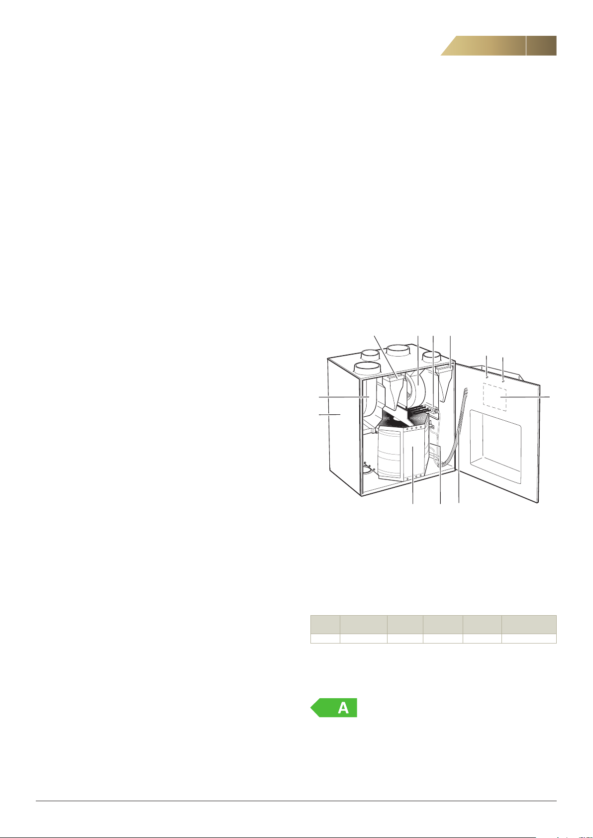
THE UNIT’S MAIN COMPONENTS
3
2
-
8
DEFROSTING
During cold periods, when frost may form in the impeller, the integrated control unit automatically activates a defrosting function. The unit
defrosts for 15 minutes every 6 hours if the outdoor temperature is
below -10 °C. The supply air fan stops and the impeller moves forward
in sections.
COOLING RECOVERY
In the summer, if the extract air is cooler than the outdoor air, the rotary heat exchanger starts to recover cooling from the cooler extract air.
This primarily applies if there is some type of cooling appliance in the
house.
ALARMS
The ISYteq Basic control panel (accessory) has a limited alarm
indicator function. The panel indicates, for instance, when there is a
temperature alarm or when the filter needs replacing.
If the ISYteq Touch 3.5 control panel (accessory) is used, the alarm will
be presented in plain text (see separate instructions).
MOISTURE CONTROL (OPTIONAL)
This function automatically limits the rotary heat exchanger’s moisture
recovery at high indoor humidity levels. This function can also be or
dered retrospectively to supplement the unit.
-
9
1. Outdoor air sensor
2. Extract air sensor
3. Supply air sensor
4. Preheater
5. Extract air fan
6. Heat exchanger
7. Supply air filter
8. Control unit
9. Casing
10. Heat exchanger motor
11. Extract air filter
12. Postheater
13. Supply air fan
ELECTRICAL DATA
Voltage: 230V, single phase, 50 Hz
Code Fan motors
Rated output, W
RDKS 2 x 83 500 500 1170 1210
1)
Rated output applies when both the preheating and the postheating devices are
installed.
Preheater
Electr., W
Postheater
Electr., W
Rated output
1)
Electr., W
Rated output
with cooker hood
ENERGY CLASS
CO2 CONTROL (OPTIONAL)
This function regulates towards a preset setpoint. The fan speed is
automatically adjusted to achieve the desired CO2 level.
NOTE! CO
tion can also be ordered retrospectively to supplement the unit.
FläktGroup DC_9295GB_20190326_R5
control requires a ISYteq Touch 3.5 control panel. This func-
2
Compliant with energy class A+ in cold climate conditions (Scandinavia).
If configured for on-demand control, the unit is compliant with energy
class A in average climate conditions (Central Europe). Ecodesign
Directive 1254/2014.
We reserve the right to make changes without prior notice
4
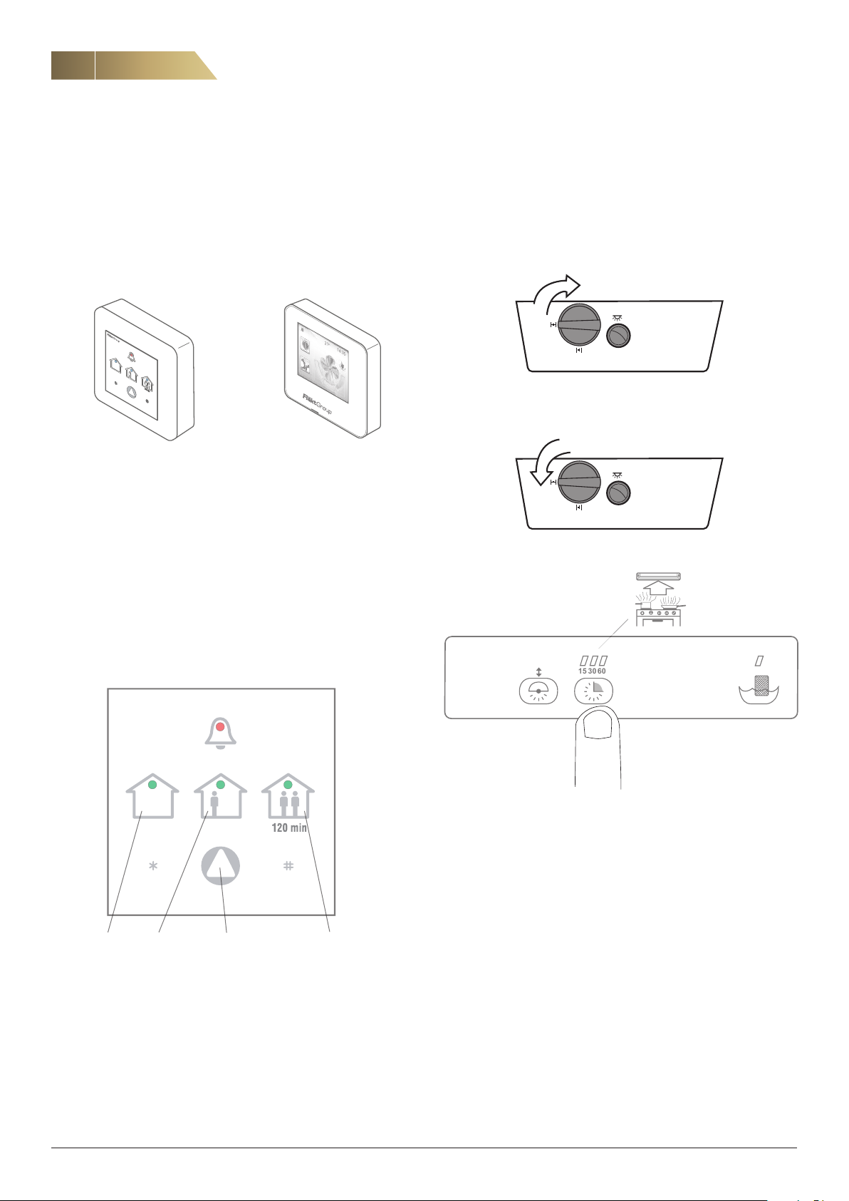
12315 30 60
15 30 60
BOOST
TRICKLE/NORMAL
14:35
21
14:35
21
ISYteq BASIC CONTROL PANEL - OPERATION
Heat recovery unit RDKS - Technical manual
The unit has a built-in control unit that controls the operation of the
fans, the rotary heat exchanger and any electric heaters.
The unit is controlled via an external ISYteq Basic or ISYteq Touch 3.5
control panel (accessory), see page 6. The control unit should be in
-
stalled in a suitable place.
After being adjusted, the unit can also be operated without a control
panel, but only in one operating mode.
ISYteq Touch 3.5ISYteq Basic
Figure 1. Control panels.
The user can select between the following operating
modes:
“AWAY” is used when there is reduced need for ventilation, e.g.
when occupants are on holiday
“HOME” used for normal ventilation flow
“FORCED” is used when there is a greater need for ventilation (au
tomatically reverts to normal after 120 minutes)
Use the arrow button to switch operating modes (see figure 2). A LED
shows the current operating mode.
UNIT WITH COOKER HOOD
When the boost damper in the cooker hood is opened, the fan
speed increases. Forced mode continues while the boost damper
remains open. After that, the fans resume normal speed.
Forced via CPDJ cooker hood.
-
Boost damper
(one press per
time setting)
AWAY
Operating modes ISYteq Basic
FläktGroup DC_9295GB_20190326_R5
HOME
operating mode)
x1 = 15 min
x2 = 30 min
x3 = 60 min
Forced via CPTJ cooker hood.
FORCEDArrow button (for selecting
We reserve the right to make changes without prior notice
Heat recovery unit RDKS - Technical manual
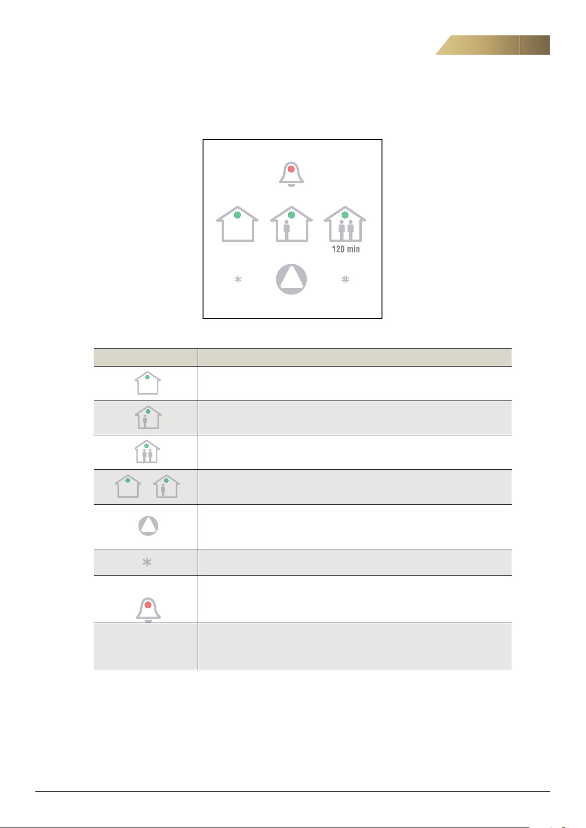
ISYteq BASIC CONTROL PANEL - OVERVIEW OF SYMBOLS AND FUNCTIONS
SYMBOLS DURING NORMAL OPERATION
HOMEAWAY FORCED
5
Symbol Description
AWAY mode
HOME mode
FORCED mode for 120 minutes
+
Min. 10 sec. Press * for a minimum of 10 seconds to reset an alarm. Also see pages 11 and 12.
No symbols illuminated
indicates that unit has
stopped.
Defrosting mode. The unit resumes normal operation after 15 minutes
Switch operating modes between: AWAY, HOME and FORCED.
Disabled during defrosting
Continuously flashing alarm symbol indicates filter alarm. See page 11.
Three flashes at intervals indicates rotor alarm. See page 12.
Steady illumination indicates temperature alarm. See page 12.
See Other alarms on page 12.
Figure 5. Symbol description ISYteq Basic.
FläktGroup DC_9295GB_20190326_R5
We reserve the right to make changes without prior notice
6
ISYteq TOUCH 3.5 CONTROL PANEL
Heat recovery unit RDKS - Technical manual
GENERAL
The control panel has a touch screen display. Use your finger or the
back of a pen to navigate in the menus.
When the power is switched on, all the menus will be imported into
the system. This will take about 20-30 seconds. After this, the home
screen will be displayed.
CLEANING OF THE DISPLAY
Disconnect the unit from the power supply by disconnecting the power
cord. Carefully wipe the display with a soft, dry, non-abrasive cloth.
If any marks remain, moisten the cloth slightly with a detergent spe
cially designed for LCD or mobile screens and wipe the screen gently
from top to bottom.
Never use other detergents, as they may contain ammonia or other
additives that could damage the display.
-
IMPORTANT:
• Never spray or pour liquids directly onto the display.
• Never clean the control panel when the system is switched on.
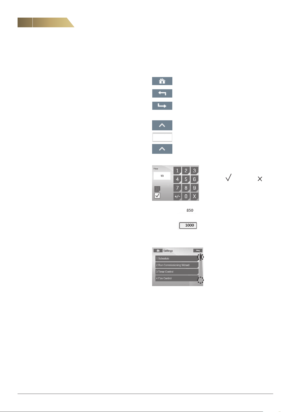
GENERAL BUTTONS AND SYMBOLS
The following buttons and symbols are universal and available on
many menu pages.
Home button, to return to the home screen.
Back button, to cancel and return to the previous page.
Confirm button, to confirm and proceed.
Use the number keys to enter a value.
Confirm with
or cancel with .
14
Changing a value.
Option 1: Press the arrow keys to increase or decrease
the value.
Option 2: Press the displayed number to enter the chosen value (see below).
Read-only values (without a surrounding
window), cannot be changed.
Editable values (surrounded by a win
dow), can be changed.
Some submenus have more than
one page. Click the upper
or lower part of the scroll list to
navigate between pages.
NOTE! The cursor cannot be
moved vertically.
-
FläktGroup DC_9295GB_20190326_R5
We reserve the right to make changes without prior notice
Heat recovery unit RDKS - Technical manual
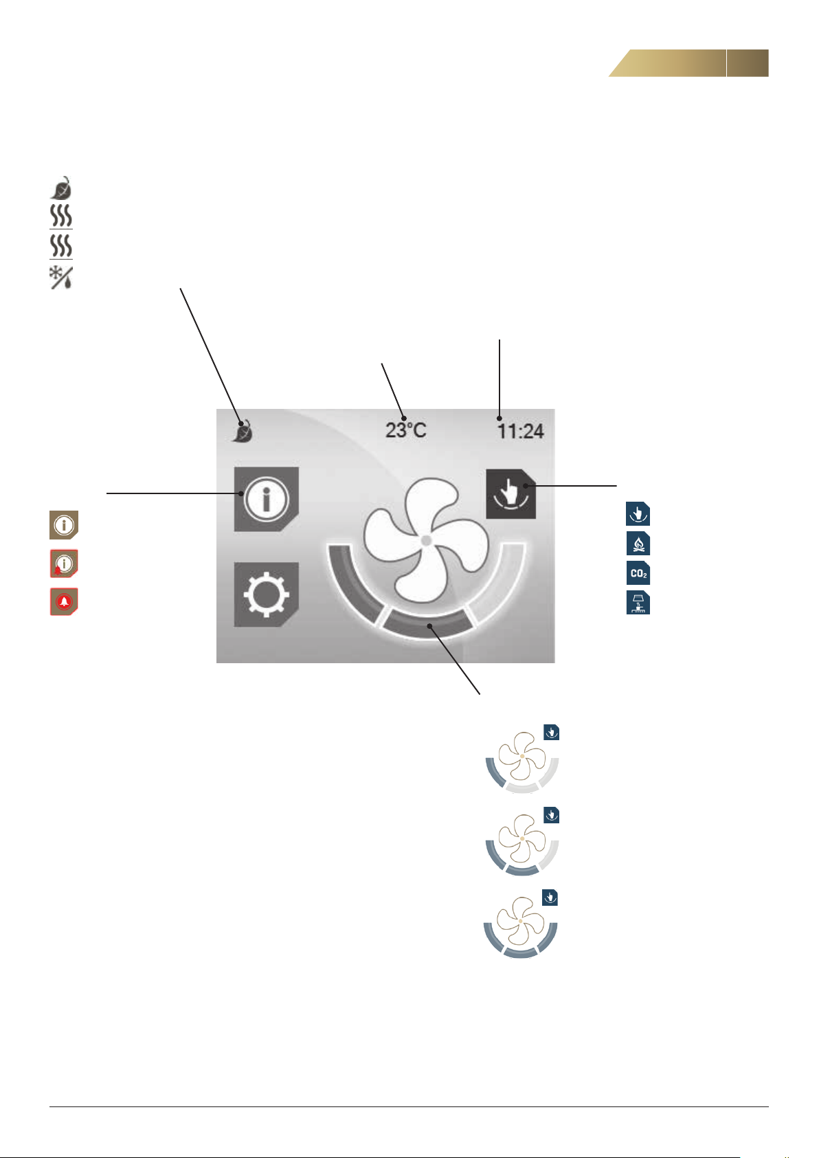
ISYteq TOUCH 3.5 CONTROL PANEL - HOME SCREEN
STATUS LINE
Heat recovery active
Postheater active
Preheater active
Defrosting in progress
7
ALARMS
No alarm
Alarm B
Alarm A
CURRENT SETPOINT,
SUPPLY AIR TEMPERATURE
CLOCK
OPERATING STATUS
Manual mode
Heating stove mode
CO2 control
Forced via cooker hood
OPERATING MODES
The user can select between the following operating modes:
“AWAY” used when there is reduced need for ventilation, e.g.
when occupants are on holiday
“HOME” used for normal ventilation flow
“FORCED” used when there is a greater need for ventilation
(automatically reverts to normal after 120 minutes)
FläktGroup DC_9295GB_20190326_R5
Away mode
Home mode
Forced mode
We reserve the right to make changes without prior notice
8
ISYteq TOUCH 3.5 CONTROL PANEL - OPERATION
Heat recovery unit RDKS - Technical manual
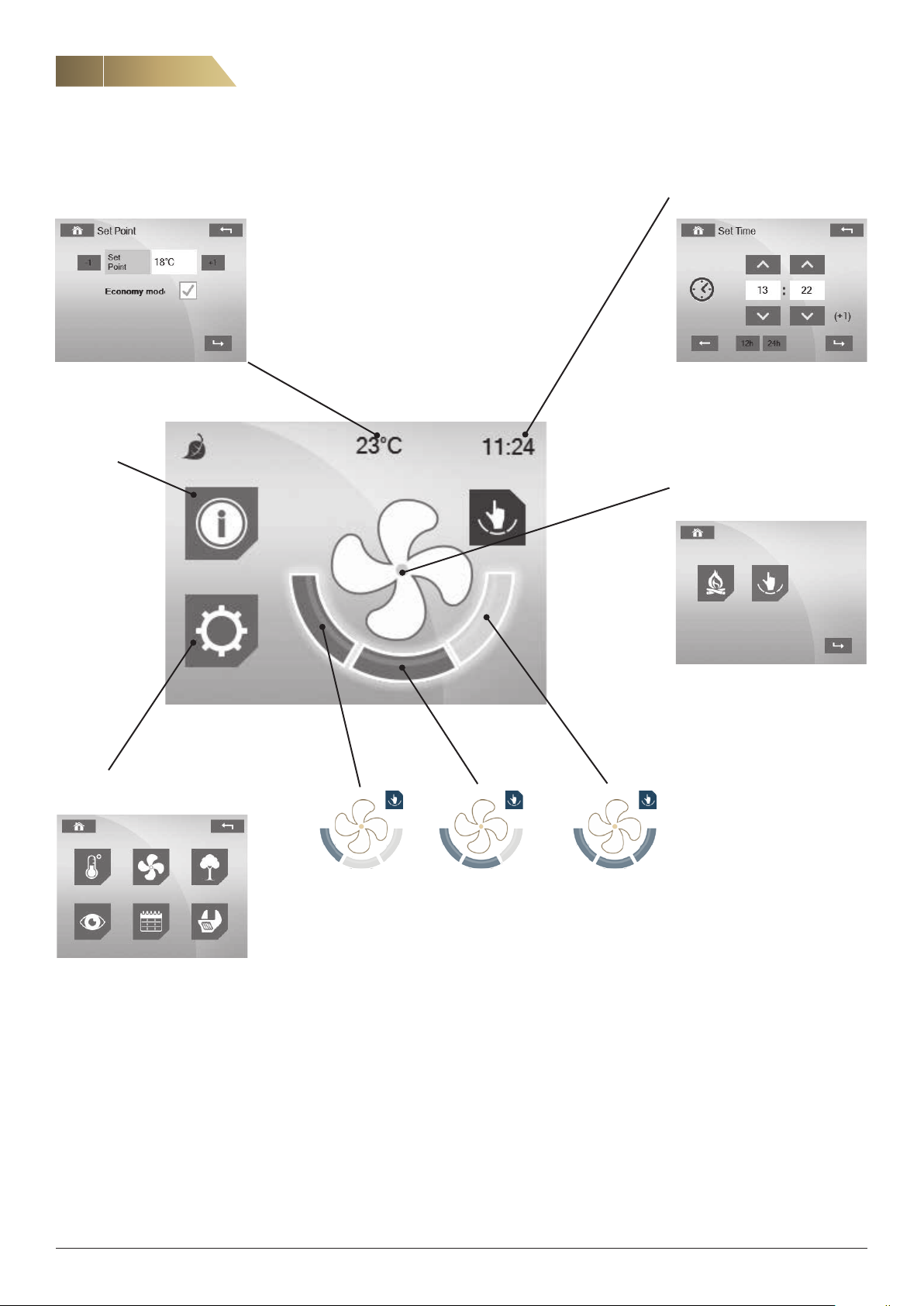
SHORTCUT TO SETTING OF TEMPERATURE SETPOINT
See page 9 for more information on temperatures.
ALARMS
See page 9.
SHORTCUT TO SETTING OF
DATE AND TIME
SELECT OPERATING STATUS
See page 9.
MENU
See page 9.
AWAY MODE HOME MODE FORCED MODE
Press the relevant field to select operating mode.
The operating mode cannot be changed during defrosting,
or during forced operation with a cooker hood.
FläktGroup DC_9295GB_20190326_R5
We reserve the right to make changes without prior notice

Heat recovery unit RDKS - Technical manual
ISYteq TOUCH CONTROL 3.5 PANEL - OPERATION
9
SELECTING OPERATING STATUS
The symbol on the home screen shows the operating status. Press the
centre of the fan symbol to change the status.
Normal mode (manual)
Heating stove mode, makes it easier to light a heating stove
or open fireplace. Temporarily creates overpressure in the
house.
ALARMS
The symbol on the home screen shows the alarm status.
No alarm
Alarm B
Alarm A
Press the icon to enter the alarm screen.
MENU
TEMPERATURES
Here you set the desired supply air temperature (setpoint).
Note: This value is not to be confused with the desired in
door temperature, which is managed by the domestic heating system. The recommended setpoint is 16–19 °C. The
factory setting is 18 °C. Temperatures, output signals etc.
are read-only values.
-
FAN STATUS
Supply and extract air fan speeds can be read from
30 –100 % or as 0 (off).
AIR QUALITY
Air quality (only available if optional moisture control or CO
control is activated). Relative humidity of the supply and
extract air can be read from 0-100% RH.
The setpoint and current CO
be read.
value (up to 2,000 ppm) can
2
2
Example 1 No alarm Example 2. Active alarms
CLEARING ALARMS
To clear an individual alarm, press Acknowledge after the relevant
alarm. To clear all the alarms, press Acknowledge All button (top right).
If the alarm cannot be cleared, it will reappear on the display and the
underlying cause for this must be resolved before the alarm can be
cleared.
A built-in timer is normally set to provide a filter replacement reminder
(alarm) every six months. If a shorter replacement interval is required
(before the alarm is due) the filter alarm can be reset under the Set
tings menu. See page 22, fig. 3.
-
ALARM HISTORY
SYSTEM OVERVIEW
Version control panel -- -- -- -- -- -- -- -- -- -- -- --IP Octet 1
Bootloader control panel --------------------IP Octet 2
Version control card ------------------------IP Octet 3
Bootloader control card -- -- -- -- -- -- -- -- -- -- --IP Octet 4
Unit type
TIME SCHEDULES
(Not applicable to domestic ventilation).
SETTINGS
See pages 22–23.
FläktGroup DC_9295GB_20190326_R5
We reserve the right to make changes without prior notice
10
MAINTENANCE AND CLEANING OF HEAT EXCHANGER AND FANS
Heat recovery unit RDKS - Technical manual
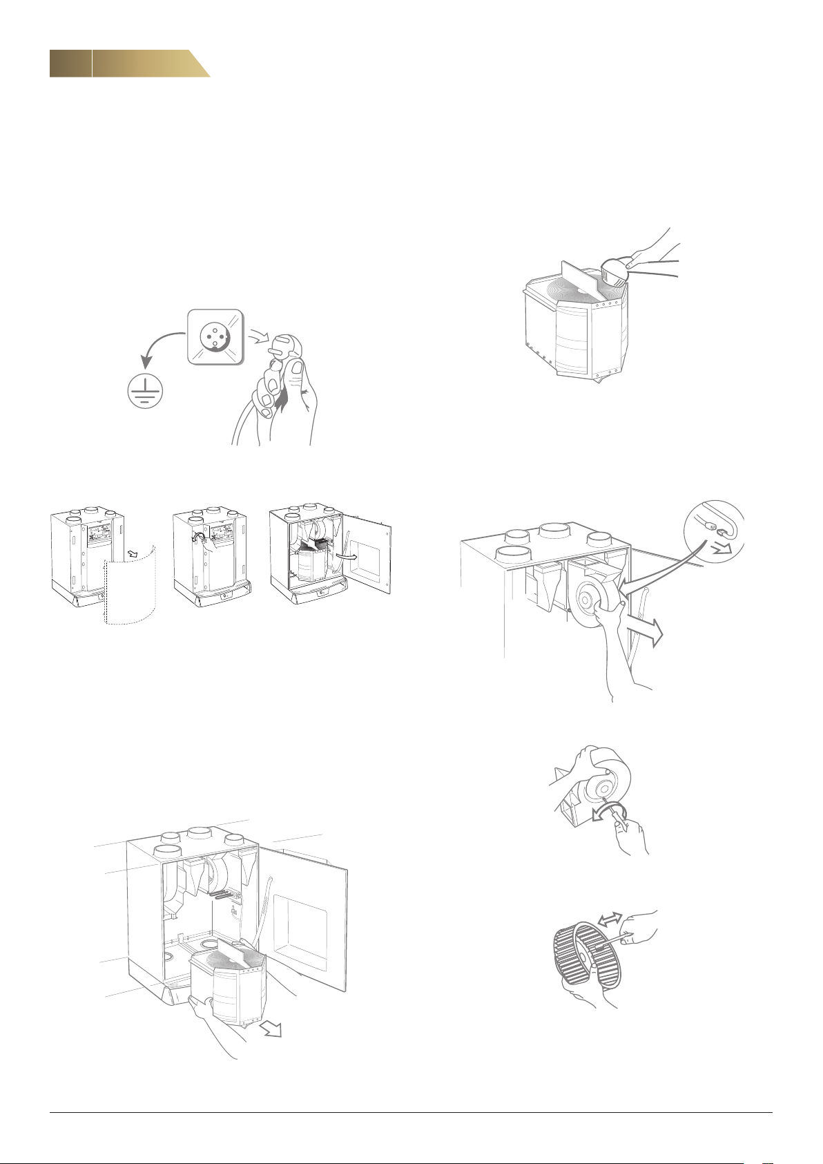
GENERAL
The fans, filters and heat exchanger are very important for the operation and economy of the unit. For this reason, it is crucial for them to
be kept clean and in good condition.
We recommend a general check-up every 6 months. For safety rea
sons, general caution should be observed during maintenance of the
unit. Be careful to avoid trapping any cables. If necessary, use protec
tive gloves.
Before cleaning the heat exchanger, fans etc., the unit should always have the power
disconnected.
Mode
LED
Param.
Mode
LED
Param.
-
-
The drive belt and seals may need replacing due to wear and tear.
Check them for damage and replace if necessary. For designations,
see spare parts list on page 33.
Vacuum clean the heat exchanger or blow clean with compressed air.
CLEANING OF FANS
Note that the fans must not be cleaned with water or other fluids; they
may only be vacuum cleaned or brushed.
Remove the unit’s front cover (if there is one). Remove the screws on the door and
open the door. The picture shows a unit with right-hand configuration (RDKS-1).
CLEANING OF THE HEAT EXCHANGER
Check that the surface of the rotor is not coated with dust. Clean with
a vacuum cleaner or by blowing through with compressed air. If vac
uum cleaning is not sufficient, hand-spray with grease dissolving fluid
and then blow clean with compressed air. Use the compressed air to
blow away from the clean side towards the dusty side.
Note! Water, acetone or similar solvents must not be used.
Remove the heat exchanger package from the unit. Disconnect the electrical con
nection to the impeller motor.
-
-
Remove the fan from the unit. Disconnect the electrical connection.
Disconnect the impeller from the fan housing by unscrewing the screws on the side
of the fan housing.
Clean the impeller housing and the fan blades with a brush or a vacuum cleaner.
NOTE! Take care not to damage any impeller housing balancers, and ensure
that no cables are trapped during reassembly.
FläktGroup DC_9295GB_20190326_R5
We reserve the right to make changes without prior notice
Heat recovery unit RDKS - Technical manual
B
A
Mode
LED
Param.
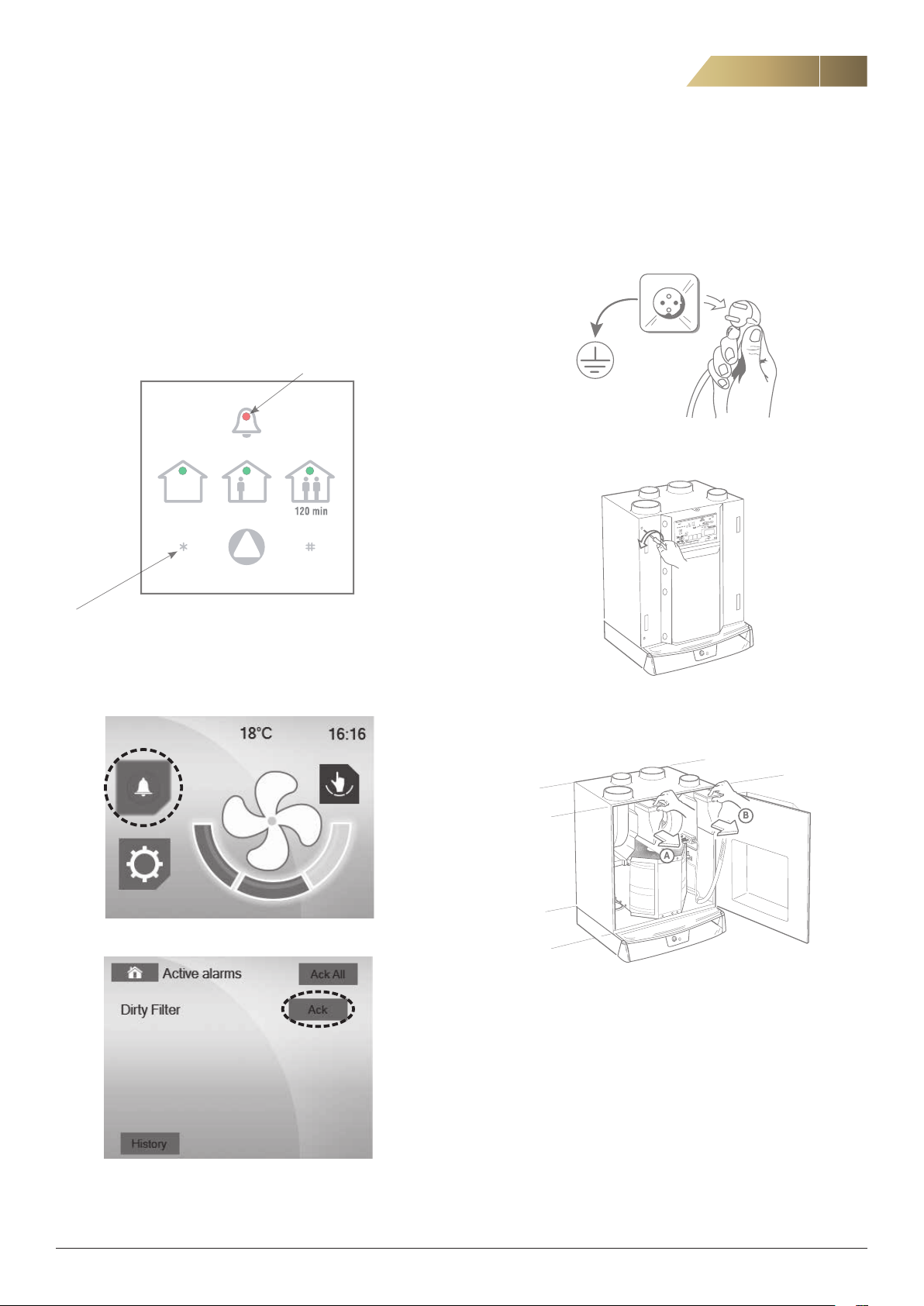
FILTER ALARM AND FILTER REPLACEMENT
11
The supply air and exhaust air filters should normally be replaced
every six months. In dirty areas, the filters may need to be replaced
more frequently.
A built-in timer is normally set to provide a filter replacement reminder
every six months.
FILTER ALARM ISYteq BASIC
When the filter needs replacing, a continuously flashing alarm light is
shown on the ISYteq Basic control panel.
A continuously flashing alarm
symbol indicates filter alarm.
After replacing the filter, reset the filter timer by pressing the * button on the
control panel for a minimum of 10 seconds.
TO REPLACE THE FILTER, FOLLOW THE STEPS BELOW.
When replacing dirty filters, use of a face mask is recommended (lowest class, FFP2).
1. Disconnect the unit from the power supply by pulling out the plug.
2. Open the door of the unit by unscrewing the two screws on the front
(see below).
FILTER ALARM ISYteq TOUCH 3.5
Press the Information/alarm button if the alarm is indicated.
The reason for the alarm is shown under active alarms.
After replacing the filter, acknowledge the alarm.
3. Pull out the supply air and exhaust air filters. Dispose of used filters
according to local waste regulations.
4. Insert new filters.
The picture shows a bag filter. A flat filter may also be used.
5. Close the door of the unit.
6. Connect the plug.
7. After replacing the filter, reset the filter alarm.
If a filter is replaced before the alarm is due, the filter replacement
timer cannot be reset via the ISYteq Basic control panel (accessory).
If there is no ISYteq Touch 3.5 control panel (accessory) on the unit
when the filter is replaced, the timer must be reset when the alarm is
due, i.e. when the set time is reached. For resetting, see page 22.
FläktGroup DC_9295GB_20190326_R5
We reserve the right to make changes without prior notice

12
Heat recovery unit RDKS - Technical manual
OVERHEATING PROTECTION, ROTOR ALARM, TEMPERATURE ALARM, OTHER ALARMS
THERMAL OVERLOAD PROTECTION
The fan motors are equipped with thermal overload protection devices,
which are reset manually by briefly disconnecting the power.
The electric heaters have two thermal overload protection devices, one
automatic and one manual. The automatic overheating protection trips
before the manual one, which means it does not normally need to be
reset.
If the manual overheating protection for the electric heater has tripped
during operation, first the power to the unit should be switched off and
then the overheating protection should be reset by pressing the reset
button.
In order to access the button, the electric heater must be disconnect
ed.
If the manual overheating protection trips again, call qualified service
personnel.
-
ROTOR ALARM
If the rotor motor stops and the Tacho signal disappears, five attempts
will automatically be made to restart the rotor (start/stop). If this does
not solve the problem, the unit will stop and the rotor alarm will be in
dicated.
-
TEMPERATURE ALARM
Generates an alarm and stops operation if the supply air temperature
drops below +5 °C. The alarm is disabled during defrosting or dur
ing forced operation with a cooker hood. A 10-minute delay ensures
that the supply air temperature has time to rise if operation has been
stopped.
-
OTHER ALARMS
The unit has various alarms that are not supported by the simple
ISYteq Basic control panel (accessory).
If any of these alarms are triggered, the unit will stop running and all
the LEDs on the ISYteq Basic will be extinguished. This also happens
in the event of power failure. A LED on the control card indicates that
the power is not switched off.
To reset these alarms, the unit must be restarted by pulling out and
reconnecting the plug.
If the ISYteq Touch 3.5 control panel (accessory) is used, the alarm will
be presented in plain text.
If the alarm recurs, service personnel will be called for assistance.
SENSOR ERROR
If any of the temperature sensors starts malfunctioning, the unit will
stop running. To reset, follow the instructions under Other alarms.
EXTERNAL ALARM
An external alarm can be connected to the unit. If this alarm is triggered, the unit will stop running To reset, follow the instructions under
Other alarms.
FläktGroup DC_9295GB_20190326_R5
We reserve the right to make changes without prior notice
 Loading...