

FläktGroup HYPOWER-GEKO Operation Manual
HYPOWER-GEKO
®
OPERATION MANUAL
HyPower-Geko
2 FläktGroup DC-2014-0022-GB 2018-05/R5 • Subject to modifications
Product range FläktGroup
HyPower-Geko
FläktGroup DC-2014-0022-GB 2018-05/R5 • Subject to modifications 3
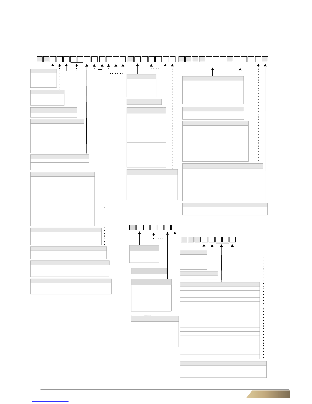
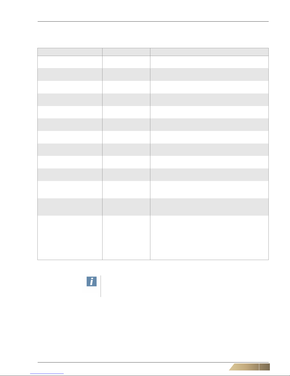
Unit Type Code
Unit type code MATRIX Controller Valve code
G H1 1.UWW3.F E0C2 D3.001.BA V G H.R325R216.1L
Model size
1 =Model size 1
2 =Model size 2
3 =Model size 3
4 =Model size 4
Capacity stage
1 = Capacity stage 1
2 = Capacity stage 2
3 = Capacity stage 3
Air-flow function
U = Recirculating-air unit
Medium function
Heating only
0W = PWW
Cooling only
W0 = PCW (pumped chilled water)
Cooling or heating
WC = Pumped chilled - warm water
Cooling and heating
WW =
Pumped chilled - warm water
Medium connection
Ceiling
3=left
4=right
Speeds
Terminal box with terminal strip
A = Speed stages 1, 2, 3
B = Speed stages 2, 3, 4
C = Speed stages 3, 4, 5
E = Speed stages 1, 3, 5
F = Min..Max (EC motor)
Metal-sheet electric switch cabinet with terminal block or for integrated control system
K = Speed stages 1, 2, 3
L Speed stages 2, 3, 4
M Speed stages 3, 4, 5
O Speed stages 1, 3, 5
S = Min..Max (EC motor)
Thermal contact
0=
AC motor - 5 speeds - with integrated motor protection
E = EC motor - continuous control - with integrated
motor protection
Condensate pump
0 = with condensate drain
1 = with condensate pump
Fan chamber
A = without fan chamber**
B = with fan chamber
C
= with fan chamber - self-contained
Filters
0 = without mat filter
2 = G2 mat filter
4 = G4 mat filter
Controller type
0=Terminal box/
Matrix 500
2 = MATRIX 2000
3 = MATRIX 3000
4 = MATRIX 4000
Controller package no.
Control panel
IP20
A = MATRIX OP21C
B = MATRIX OP30C
C = MATRIX OP31C
D = MATRIX OP44C
E = MATRIX OP50C
F = MATRIX OP51C
U = MATRIX OP20C
1=CMS
2=CMT 40
3=CMT 20
4=CMT 2Z
J = CET.ACEC
Z = without control panel
Unit type
Master unit, control panel
A=
Individual/master unit,
control panel included
C=
Master unit
without control panel
D=
Slave unit
without control panel
Function type
R=3-point 230V
T=2-point 230V
N=3-point 24V
Q=2-point 24V
S = 0-10 V, 24 V
C=
3-point 230 V + 2 contacts
Valve body
2=2-way
3=3-way
Kvs-value
03 = K
vs
0,25 (R, N, S, C)
04 = Kvs 0.40 (R, N, S, C)
06 = Kvs 0.63 (R, N, S, C)
10 = Kvs 1,0 (R, N, S, C)
16 = Kvs 0,40 (R, N, S, C, T, Q)
25 = Kvs 2.5 (R, N, S, C, T, Q)
40 = Kvs 4.0
(R, N, S, C, T, Q)
63 = Kvs 6.3
(R, N, S, C, T, Q)
80 = Kvs 8.0 (R, N, S, C, T, Q)
Connection/shut-off
0 = Inlet/outlet flow with outside thread
1 = Inlet/outlet with solder fitting
2 = Inlet/outlet + ball trap with external screw thread
3 = Inlet/outlet + ball trap with solder fitting
4 = Inlet + ball trap/
outlet + shut-off valve with external screw thread
5 = Inlet + ball trap/
outlet + shut-off valve with solder fitting
Medium connection
L = Left
R=Right
Cooling/heating circuit Heating circuit
Model size
1 = Model size 1
2 = Model size 2
3 = Model size 3
4 = Model size 4
Accessory class
A = Air-side accessories
Accessory types
Inlet side (intake)
03 =
Air-intake plenum with round connecto r (not self- con-
tained)
11 = Intake flexible connection
21 = Intake sound absorber connection
51 = Air intake grille (intervention protection)
Discharge side (outlet)
04 =
Discharge plenum with round connector (self-con-
tained)
11 = Air discharge flexible connection
21 = Air discharge sound attenuator connection
91 = Air discharge transition piece
Other
61 = Suspension rail - 950 mm
62 = Suspension rail - 1550 mm
63 = Suspension rail - 2150 mm
71 = Seal cap for round connector (self-contained)
82 = Spare filter G2
84 =
Spare filter G4
Intake - discharge side
1 = Inlet side (intake)
2 = Discharge s ide (outlet)
3 = Other
Z G H.1 A 0 3 1
Accessories code
*) Connection side from front , viewing the discharge
**) not certified as of VDI 6022
***) Required accessories for mounting on discharge side from
FläktGroup
Controller type
0 = Terminal box
1=
Module 3010
2=
Module 3020
A 0.0 0 1.1 A
ISYteq Controls
Controller package Nr.
Control panel
1 = CET.ACEC
2=CMT 4D
3=CMT 2D
4=CMT 2Z
A = ISYteq LCD
B = ISYteq Touch
Z = without control panel
UU = MATRIX OP20C
Unit type
Master unit, control panel
A=
Individual/master unit,
control panel included
C=
Master unit
without control panel
D=
Slave unit
without control panel

Table of Contents HyPower-Geko
4 FläktGroup DC-2014-0022-GB 2018-05/R5 • Subject to modifications
1 Safety and User Instructions ......................................................6
1.1 Availability of the operation manual .................... .... .... .... ..... .. 6
1.2 Symbols used ............................ .... .... .... ................................ 6
1.3 Safety instructions: warning and danger symbols ................. 6
1.4 Safety-conscious work procedures ........................................7
1.5 Personnel selection and qualification .................................... 8
1.6 Proper use ........................ .... ..... .... .... .... .... ..... .... .... .... .... ..... .. 8
1.7 Improper use ..................................... .... .... ..... .... .... .... .... ..... .. 9
1.8 Safety regulations and codes ................................................ 9
1.9 Modifications and changes .................................................... 9
1.10 Spare parts ..........................................................................9
2 Technical Description ...............................................................10
2.1 Basic unit components ........................................................ 10
2.2 Material specification ................. .... .... .... .... ..... .... .... .... .... ..... 12
2.3 Range of application ............................................................ 12
2.4 Dimensions ..... ..... .... .... .... .... ..... .... .... .... .... ..... .... .... .... .... ..... 15
2.5 Unit data ........................... .... ..... .... .... .... .... ..... .... .... .... .... ..... 18
2.6 Condensate pump ......................... .... ........ ..... .... .... .... .... ..... 19
2.7 Air side accessories ............................................... .... .... ..... 21
2.8 Commission Regulation (EU) 2016/2281 ............................ 22
3 Shipping and storage ................................................................24
3.1 Transport safety ................................................. .... .... .... ..... 24
3.2 Packaged content ............. .... ..... .... .... .... .... ..... .... .... .... .... ..... 24
3.3 Packaging ................. .... .... .... ..... .... .... .... .... ..... .... .... .... .... ..... 24
3.4 Transport .......................... .... ..... .... .... .... .... ..... .... .... .............24
3.5 Temporary storage ................................ .... ..... .... .... ........ ..... 25
3.6 Disposal ........... ..... .... .... .... .... ..... .......................................... 25
4 Mounting ....................................................................................26
4.1 Installation site ...... .... .... .... .... ..... .... .... .... .... ..... .... .... .... .... ..... 26
4.2 Recommended service opening for maintenance work
on the basic unit ........................................................................ 27
4.3 Pre-installation work .......................... .... .... ..... .... .... .... .... ..... 29
4.4 Unit mounting ........................................ .... ..... .... ................. 30
5 Hydraulic Connection ...............................................................41
5.1 General ................. .... .... .... .... ..... .... .... .... .... ..... .... .... .... .... ..... 41
5.2 Overview of valves ................................ .... ..... .... .... .... .... ..... 41
5.3 Heating and cooling connections for units without valves
or with on-site valves provided by others .................................. 43
5.4 Heating and cooling water connections for units with
factory-mounted valves ............................................................. 46
5.5 Connecting condensate drain ........ .... .... .... ..... .... .... .... .... ..... 51
5.6 Connecting condensate pump ............... .... ..... .... .... .... .... ..... 52
6 Electrical connection ................................................................54
6.1 Connection diagrams ................................................. .... ..... 54
6.2 Terminal box or electric switch cabinet ................................ 54
6.3 Fan speed ................................................. .......................... 55
6.4 Connection with controls provided by others ....................... 56

HyPower-Geko Table of Contents
FläktGroup DC-2014-0022-GB 2018-05/R5 • Subject to modifications 5
6.5 Overview of the FläktGroup MATRIX control electronics .....61
6.6 Mounting control panel .........................................................62
6.7 Electrical connection with MATRIX ......................................63
6.8 Network and shielding connection MATRIX.Net ................70
6.9 Electrical connection of FläktGroup miniature switches/relay
PCB for units with AC fans .........................................................76
6.10 Electrical connection for AC fan with FläktGroup miniature
switches CMS and CMT ............................................................77
6.11 Electrical connection of FläktGroup miniature switches
CET.ACEC for units with AC fans ..............................................82
6.12 Electrical connection of FläktGroup miniature switches
CET.ACEC for units with EC fans ..............................................87
7 Commissioning .........................................................................93
7.1 Safety check ........................................................................93
7.2 Checking the control and shut-off valves .............................95
7.3 Vent the unit .......................................................................100
7.4 Checking the condensate drain .........................................100
7.5 Terminating resistors .........................................................101
7.6 Setting address ..................................................................103
7.7 Setting limitation functions ................................................. 105
7.8 Switch on unit .....................................................................107
7.9 Checking data connection .................................................108
7.10 Checking control inputs and outputs ................................109
7.11 Check condensate pump (applies only to cooling units
with condensate pump) ............................................................111
7.12 Functional characteristics for the use of MATRIX ...........112
8 Maintenance and Troubleshooting ........................................115
8.1 Maintenance ......................................................................115
8.2 Quarterly maintenance .......................................................117
8.3 Annual maintenance ..........................................................119
8.4 Before cooling season .......................................................126
8.5 Breakdowns .......................................................................128
9 EC Declaration of Conformity.................................................131
– Original operation manual –
Copyright note
Disclosing, copying, distributing or taking any action in reliance on the contents of this document is strictly prohibited
without express prior consent. Violations entail liability for any damages or other liability arising. All rights in relation to
patents, utility patents or design patents are reserved.

Safety and User Instructions HyPower-Geko
6 FläktGroup DC-2014-0022-GB 2018-05/R5 • Subject to modifications
1 Safety and User Instructions
This is an original operation manual verified by the manufacturer.
HyPower fan coil units are developed and manufactured in accordance with the stateof-the-art technological standards, established technical safety codes and EC Directive on Machinery.
Use the unit when it is in a technically sound condition for the intended purpose observing the current operation manual, taking safety aspects and potential hazards into
account! Otherwise failure to follow these instructions may result in death or injury to
the user, third persons or damage to the unit, connected units or other equipment.Have
all faults repaired by an authorized specialist without delay!
1.1 Availability of the operation manual
This operation manual contains important instructions rega rding safe and proper operation of the unit.
This operation manual applies to installation companies, operators, building technicians, technical personnel or instructed persons as well as electricians.
This operation manual must be available at the loca tion of the unit at all times. When
working on the equipment, observe all instructions and precautions in the current operation manual, in particular the chapter on safety.
1.2 Symbols used
The following symbols are used to highlight particular text sections in this operation
manual:
– This symbol is used to indicate lists.
• This symbol indicates handling instructions.
9 This symbol indicates the result of an action.
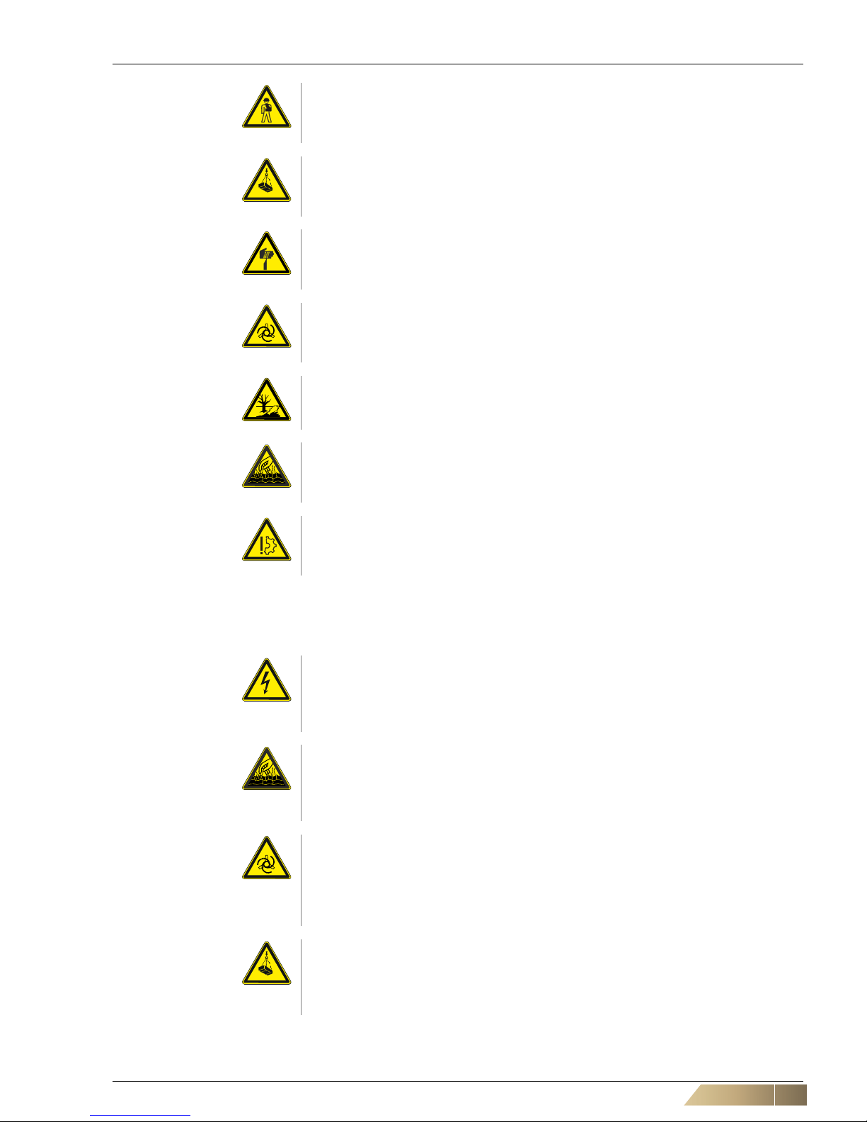
1.3 Safety instructions: warning and danger symbols
All information in this chapter is important and relevant for your safety. That is why not
all of the information contained in the present chapter is labelled with special danger
pictograms.
In subsequent chapters of this manual, warning notes are indicated by pictograms.
General safety instructions are listed at the beginning of the respective chapter and
special safety instructions on specific jobs are listed along with the respective steps.
The following warnings are used:
User instructions!
User instructions provide optimal, efficient and environmentally friendly methods for
using and handling the units.
Recycling
This symbol is used to highlight instructions on proper reuse of packaging material
and disused components and assembly groups (separated according to recyclable
materials, e.g. metal, plastic, etc.).
Danger of electrical current!
This symbol indicates a risk of electrical shock that can result in serious injury, death
and material damage.
HyPower-Geko Safety and User Instructions
FläktGroup DC-2014-0022-GB 2018-05/R5 • Subject to modifications 7
1.4 Safety-conscious work procedures
To ensure your own safety, comply with the following safety instructions:
Risk of personal injury!
This symbol indicates (different from the above-mentioned danger types) a h azardous location with a risk of personal injury including death and material damage.
Danger due to overhead loads!
This symbol indicates a hazardous suspended load with a risk of personal injury
including death and material damage.
Danger - sharp cutting edges!
This section specifies procedures and precautions for preventing personal injury
resulting from cuts caused by sheet metal.
Warning: risk of rotating components!
This symbol indicates hazardous rotating parts with a risk of personal injury including death and material damage.
Risk of environmental damage!
This symbol warns about possible damage to the environment.
Danger of scalding!
This symbol indicates a risk of scalding from leaking hot liquids that can result in personal injury, including death and material damage.
Risk of damage to the unit!
This symbol indicates a hazardous location with a risk of material damage that can
also lead to personal injury.
Danger of electrical current!
Before carrying out any jobs on the unit, power the unit down to prevent injury from
electrical current. Ensure that the unit is secured against being switched on again at
an appropriate point of the on-site power supply.
Danger of scalding!
Before performing work on the valves or the inlet or outlet pipes, seal o ff the heating
or cooling medium inlet to prevent scalding. Commence work only after the heating
medium has cooled down.
Warning: risk of rotating components!
Rotating fan impeller wheel poses a risk of injury! Before performing any work on
the unit, ensure that the unit is disconnected and not under voltage. Ensure that the
unit is properly secured against subsequent switch-on at an appropriate point of the
on-site power supply.
Danger due to overhead loads!
Wear a helmet and safety boots to prevent injury from falling components, especially when fitting the unit to the ceiling. Ceiling installations should always be performed by two persons.
Safety and User Instructions HyPower-Geko
8 FläktGroup DC-2014-0022-GB 2018-05/R5 • Subject to modifications
The following accident prevention regulations apply (VBG1, BGV A2 (previously:
VBG4), VBG7w, VBG9a) and generally recognized codes for machinery and principles
of engineering, particularly DIN VDE 0100, DIN VDE 0105.
1.5 Personnel selection and qualification
The unit may be installed, operate d and maintained only by qualified, spe cially trained
and authorized staff. The following tasks described in the operation manual and the
service manual may only be performed by qualified personnel:
– Shipping and storage
– Assembly
– Hydraulic connection
– Electrical connection
– Commissioning
– Maintenance
1.6 Proper use
Fan coil units of the HyPower Geko series are exclusively designed for heating, filtering
and cooling purposes. Water or water/glycol solution (max. 50%) may be used as the
medium.
The following limit values apply to medium for operating Cu/Al heat exchangers:
Risk of personal injury!
Always wear protective gloves when shipping or installing the unit to prevent injury
caused by sharp edges.
Risk of damage to the unit!
During the installation it must be ensured that no condensation or splash water penetrates into electric units, also in the event of unit/installation damage.
Parameter Unit Value
pH value (at 20 °C) 7.5 - 9
Conductivity (at 20 °C) μS/cm < 700
Oxygen content O
2
mg/l < 0.1
Total hardness °dH 1 - 15
Dissolved sulfur S not detectable
Sodium Na
+
mg/l < 100
Iron Fe
2+
, Fe
3+
mg/l < 0.1
Manganese Mn
2+
mg/l < 0.05
Ammonium content NH
4
+
mg/l < 0.1
Chloride Cl
-
mg/l < 100
Sulphate SO
4
2-
mg/l < 50
Nitrite NO
2
-
mg/l < 50
Nitrate NO
3
-
mg/l < 50
Tab. 1-1: Limit values for medium used in closed heating and cooling circuits
HyPower-Geko Safety and User Instructions
FläktGroup DC-2014-0022-GB 2018-05/R5 • Subject to modifications 9
The HyPower-Geko may only be operated indoors.
The HyPower-Geko is designed for wall and ceiling installation.
1.7 Improper use
The HyPower-Geko may not be operated:
– for handling outdoor air,
– in areas subject to explosion risk,
– in wet areas or
– in locations with high dust levels or aggressive air.
1.8 Safety regulations and codes
When carrying out installation, commissioning, maintenance and service of the FlexGeko units, all local safety regulations and codes as well as generally established technical practices must be followed.
1.9 Modifications and changes
No changes, add-ons or modifications may be performed on the HyPower-Geko air
treatment unit or its components.
Changes or modifications of the Flex-Geko unit will invalidate the CE conformity and
render all warranty claims null and void.
1.10 Spare parts
Only original FläktGroup spare parts are allowed, since FläktGroup is not liable if thirdparty spare parts are used.
Risk of damage to the unit!
In open systems (e.g. when using well water), used water should additionally be
cleansed of suspended matter using a filter to be installed at the inlet. Failure to do
so could result in a risk of erosion by suspended matter (consider the limit values
specified in Tab. 1-1).
Also ensure that the unit is protected from dust and other substances that can cause
acidic or alkaline reaction with water (aluminum corrosion).
It is not allowed to use HyPower units, in particular with a cooling function, for suction
of kitchen exhaust air containing organic acids, e.g. vinegar, formic acid or materials
containing aldehyde (e.g. cinnamic aldehyde). This can lead to corrosion of aluminium fins. As a consequence unpleasant odours may occur.
User instructions!
The unit is considered to be used in an improper manner if it is applied for other pur-
poses or a purpose that is not covered by the scope of the given operation manu al.
The manufacturer or supplier is not liable for any resulting damage; the user alone
bears the full risk.
The operator is responsible for proper use.
Proper use also stipulates the observance of the operation manual and the inspec-
tion and maintenance conditions defined by FläktGroup.
Risk of personal injury!
Improper use can cause personal injury and material damage.
Technical Description HyPower-Geko
10 FläktGroup DC-2014-0022-GB 2018-05/R5 • Subject to modifications
2 Technical Description
2.1 Basic unit components
*) Without fan chamber VDI 6022 certification is not applicable!
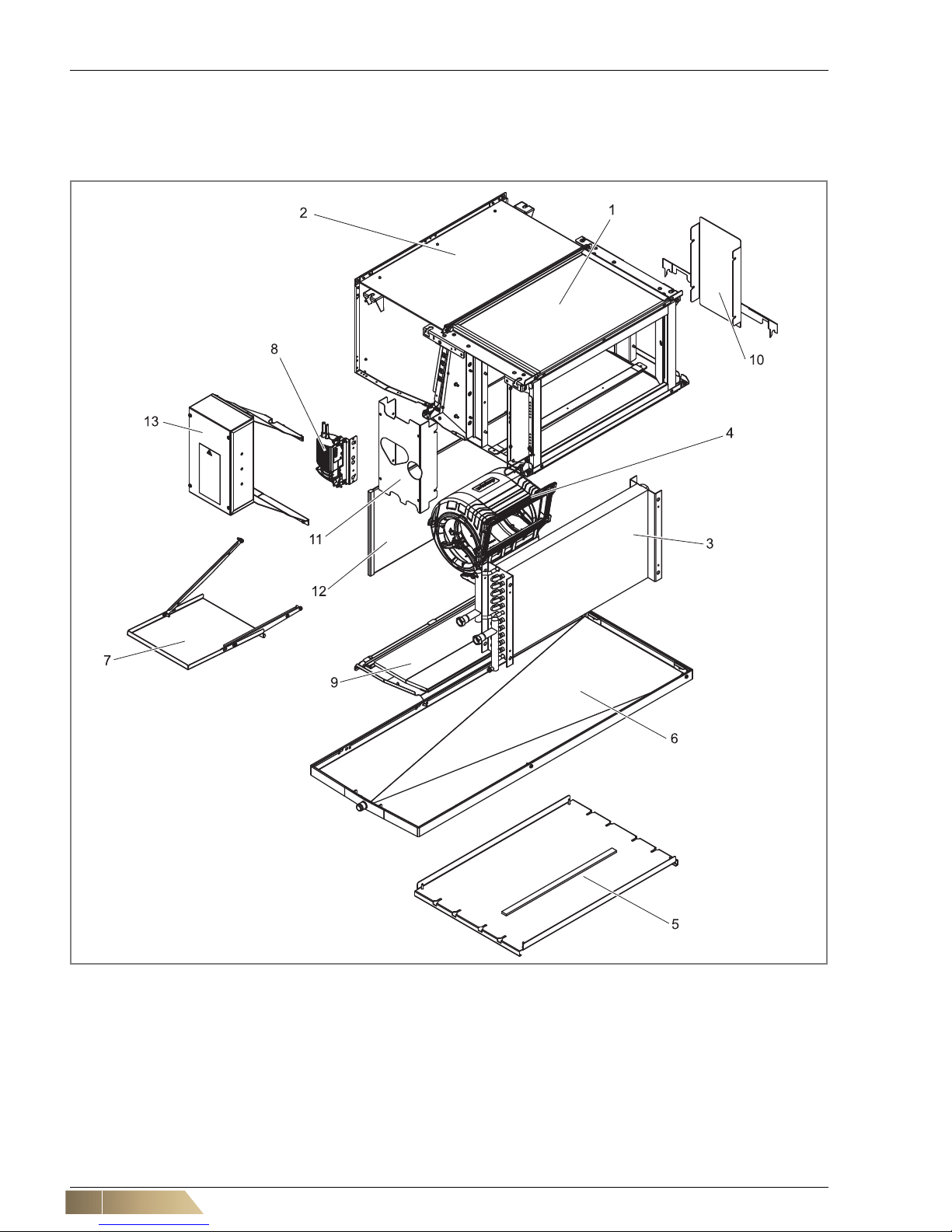
Fig. 2-1: Basic unit components
Pos. 1: Basic casing (incl. assembly mountings)
Pos. 2: Fan chamber (optional)*
Pos. 3: Heat exchanger: Cu/Al
Pos. 4: Fan
Pos. 5: Bottom basic casing cover (instead of condensate tray
Pos. 6, for heating-only units)
Pos. 6: Condensate tray (optional)
Pos. 7: Auxiliary condensate tray
(only for unit type U - GH##.U###.#####)
Pos. 8: Condensate pump (optional)
Pos. 9: Service panel
Pos. 10: Cover for heat exchanger and condensate drain
Pos. 11: Heat exchanger cover (only for unit type H
- GH##.H###.#####)
Pos. 12: Filter
Pos. 13: Electric switch cabinet (optional)

HyPower-Geko Technical Description
FläktGroup DC-2014-0022-GB 2018-05/R5 • Subject to modifications 11
Various unit parts indicated in fig. 2-1 are specified in detail below.
Basic casing (incl. assembly mountings) (pos. 1)
The basic casing consists of a single-form panel design made of galvanized sheet
steel with external insulation made of PE. The assembly mountings are for the ceiling
assembly of the unit and are a component of the basic casing.
Fan chamber (optional)* (pos. 2)
*)
The fan chamber consists of a single-form panel design made of galvanized sheet
steel (optionally with inside insulation with a glass-fiber laminated mineral wool).
*) Without fan chamber VDI 6022 certification is not applicable!
Heat exchanger: Cu/Al (pos. 3)
The heat exchanger for chilled and warm water has connecting spigots with internal
thread as well as air vents and drain valves. Depending on the unit application, the heat
exchanger is equipped with two connecting spigots (water inlet and outlet in a 2-pipe
system) or with four connecting spigots (water inlet and outlet in a 4-pipe system).
Fan (pos. 4)
The fan consists of one or two centrifugal fans fitted with AC or EC motors. The centrifugal fans are equipped with low-noise, maintenance-free sleeve bearings for AC
motors and ball bearings for EC motors. The continuously variable EC motor is
equipped with integrated control electronics and blockage protection.
Protection class IP20 and insulation class F.
Bottom basic casing cover (instead of condensate tray Pos. 6, for heating-only
units) (pos. 5)
For heating-only units bottom basic casing cover is mounted instead of condensate
tray Pos. 6.
Condensate tray (optional) (pos. 6)
In the HyPower-Geko, the condensate tray is for the collection of the condensation
water forming at the heat exchanger.
Auxiliary condensate tray (only for unit type U - GH##.U###.#####) (pos. 7)
Additional condensate tray for the collection of condensation water from the control
valves and shut-off instruments.
Condensate pump (optional) (pos. 8)
The condensate pump is used to forward forming condensate into higher located collection vessels, if a free drain is not possible.
Service panel (pos. 9)
The service panel provides easy access to the unit's internal components.
Cover for heat exchanger and condensate drain (pos. 10)
The protective cover is made if galvanized metal sheet (without insulation).
Heat exchanger cover (only for unit type H - GH##.H###.#####) (pos. 11)
Heat exchanger cover is made of galvanized metal sheet (without insulation) and is
only used for unit type H.
Filter (pos. 12)
The filter consists of a filter hose with a clip-on frame and plastic clamping rail.
Electric switch cabinet (optional) (pos. 13)
Depending on the version, the switch box made of plastic or galvanized sheet steel
contains:
– One or more printed circuit board(s)
– terminal block(s).
Technical Description HyPower-Geko
12 FläktGroup DC-2014-0022-GB 2018-05/R5 • Subject to modifications
2.2 Material specification
2.3 Range of Application
2.3.1 Water inlet temperature
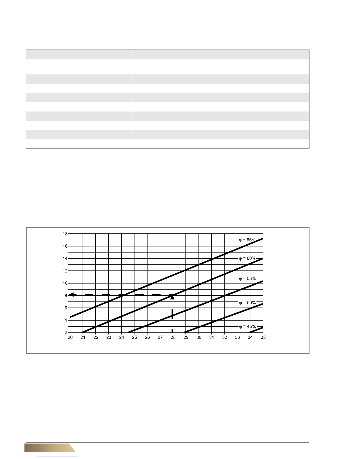
To prevent condensate from forming on non-insulated casing parts when th e temperature falls below the dew point during cooling opera tion, certain minimum inlet temp eratures must be maintained. These temperatures depend on ambient temperature and
indoor relative humidity and are specified in the following diagram.
Example:
The room temperature is 28°C, the relative humidity is 60%. According to the diagram
(fig. 2-2), the minimum allowable water inlet temperature is 8°C.
Unit part Material
Fan chamber (optional) Galvanized sheet steel (optionally: insulation made of mineral wool laminated
with glass fiber)
Basic casing (including assembly mountings) Galvanized steel sheet, insulation PE
Heat Exchanger Copper/aluminium (copper/copper, copper/alodine)
AC and EC-Motor Different materials
Connecting cable Different materials
Fan with casing Plastic
Condensate pan Galvanized sheet steel with polyethylene thermal insulation on the underside
Filter Filter fleece, synthetic
Auxiliary drain pan Galvanized metal sheet
Tab. 2-1: Material specification of unit components
Fig. 2-2: Minimum allowed water inlet temperature as a function of indoor air condition; air pressure = 1013 hPa; j = relative hu-
midity
Water inlet temperature in °C
Room temperature in °C
HyPower-Geko Technical Description
FläktGroup DC-2014-0022-GB 2018-05/R5 • Subject to modifications 13
2.3.2 External air side resistance
2.3.3 Unit and heat exchanger
User instructions!
The on-site external air-side resistance may not exceed the values 200 Pa at 300
m3/h for size 1, 500 m3/h for size 2, 700 m3/h for size 3 and 1000 m3/h for size 4.
Unit and heat exchanger Values
Max. operating pressure/temperature 1.6 MPa (16 bar) / 90 °C
Max. allowed ambient temperature 40 °C
Min. allowed ambient temperature 2 °C
Operating voltage 230 V AC, 50/60 Hz
Power consumption/protection class Refer to name plate
Max. discharge temperature 75 °C (fire hazard)
Tab. 2-2: Operating limits for unit and heat exchanger
Model size Capacity
size
Maximum medium flow rate [l/h]
2-pipe
cooling or heating
circuit
4-pipe cooling
circuit
4-pipe
heating circuit
11
2
3
700
1400
2100
1050
1400
-
342
685
-
2 1
2
3
1050
2100
3160
1580
2100
-
514
1027
-
31
2
3
1400
2800
4200
2100
2800
-
685
1370
-
4 1
2
3
1400
2800
4200
2100
2800
-
685
1370
-
Tab. 2-3: Maximum allowed medium flow rate
Technical Description HyPower-Geko
14 FläktGroup DC-2014-0022-GB 2018-05/R5 • Subject to modifications
2.3.4 Valves with modulating actuators
2.3.5 Valves with thermoelectric actuators
2.3.6 Valves with continuous actuators
Valves with modulating
actuator 230 V/24 V
Values
230 V 24 V
Max. operating pressure/inlet temperature 1.6 MPa (16 bar) / 110 °C
Max. allowed ambient temperature 60 °C
Operating voltage 230 V AC
50/60 Hz
24 V AC
50/60 Hz
Power consumption/protection class 0.7 VA/IP43
Running time 120 s (50 Hz)
100 s (60 Hz)
150 s (50 Hz)
125 s (60 Hz)
Water Max. 50% glycol share allowable
Tab. 2-4: Operating limits for valves with modulating actuators
Valves with modulating servo drives 230 V and 2
voltage-free auxiliary switches
Values
Max. operating pressure/inlet temperature 1.6 MPa (16 bar) / 110 °C
Max. allowed ambient temperature 60 °C
Operating voltage 230 V AC, 50/60 Hz
Power consumption/protection class 0.7 VA/IP43
Running time 150 s (50 Hz); 125 s (60 Hz)
Load capacity for auxiliary switch Max. 5 (1) A/250 V
Max. 100 mA/24 V
Water Max. 50% glycol share allowable
Tab. 2-5: Operating limits for valves with modulating actuators and auxiliary switches
Valves with thermoelectric actuators
230 V/24 V
Values
M100
230 V
M100
24 V
MT4
230 V
MT4
24 V
MT8
230 V
MT8
24 V
Max. operating pressure/inlet temperature 1.6 MPa (16 bar) / 110 °C
Max. allowed ambient temperature 50 °C
Operating voltage 230 V AC
50/60 Hz
24 V AC
50/60 Hz
230 V AC
50/60 Hz
24 V AC
50/60 Hz
230 V AC
50/60 Hz
24 V AC
50/60 Hz
Power consumption/protection class 3 VA/IP43 3 VA/IP44 3 VA/IP44
Running time 180 s 280 s 150 s 240 s 210 s 360 s
water Max. 50% glycol share allowable
Tab. 2-6: Operating limits for valves with thermoelectric actuators
Valves with continuous actuators Values
Max. operating pressure/inlet temperature 1.6 MPa (16 bar) / 110 °C
Max. allowed ambient temperature 60 °C
Operating voltage 24 VAC, 50/60 Hz
Analog control signal 0 - 10 (2 - 10) V
Power consumption/protection class 1.4 VA/IP43
Running time 150 s (50 Hz); 125 s (60 Hz)
Water Max. 50% glycol share allowable
Tab. 2-7: Operating limits for valves with continuous actuators
HyPower-Geko Technical Description
FläktGroup DC-2014-0022-GB 2018-05/R5 • Subject to modifications 15
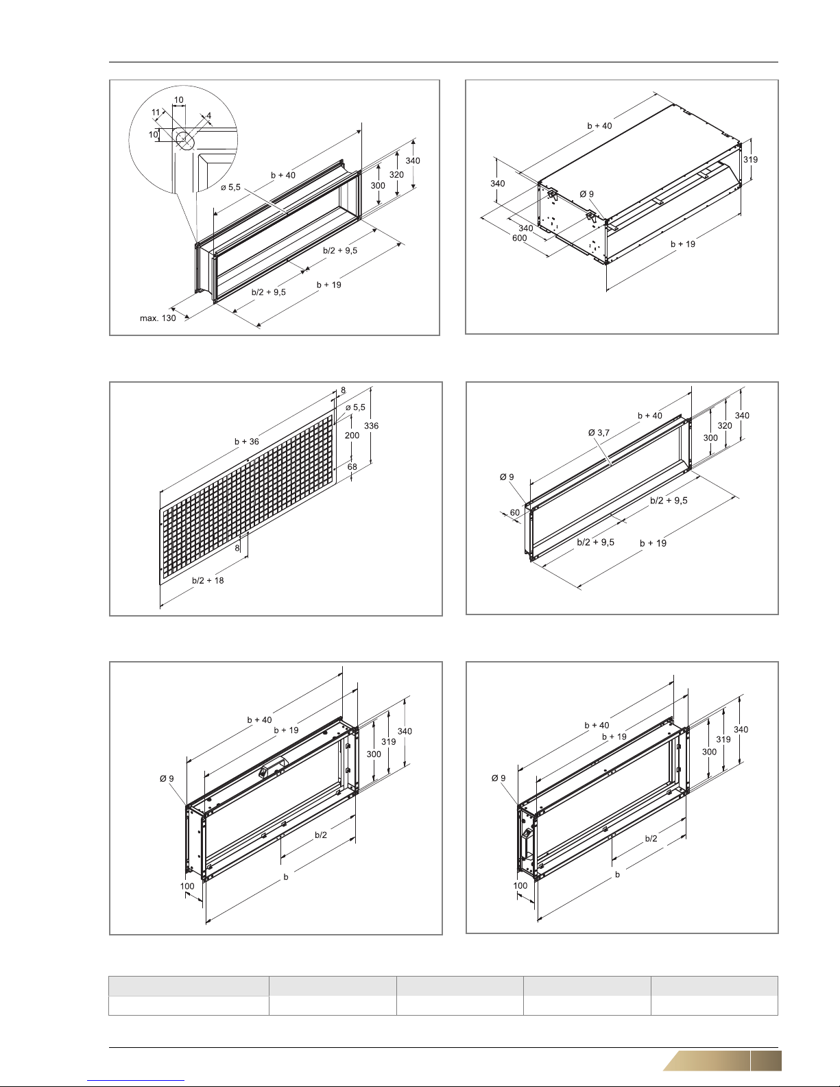
2.4 Dimensions
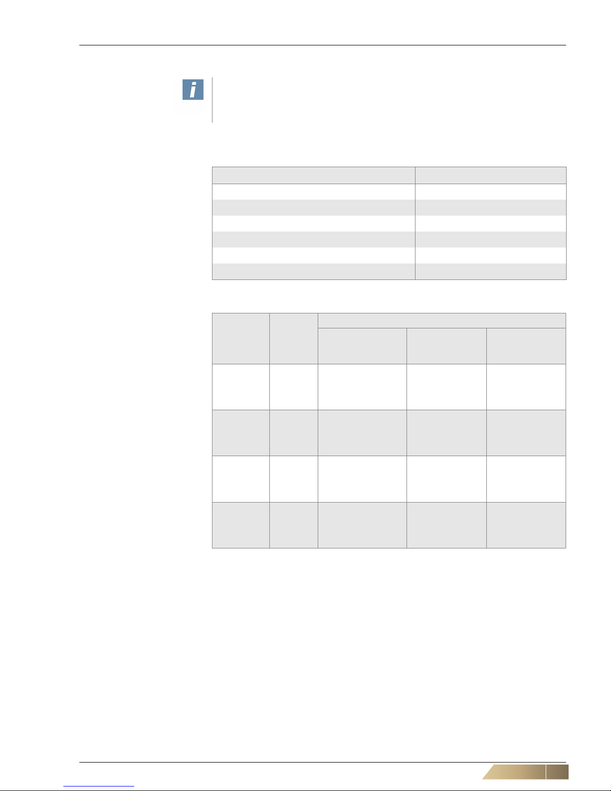
2.4.1 Basic unit
Fig. 2-3: Dimensions for unit type U without fan chamber (A) (not certified as of VDI 6022) - GH##.U###.###A0
Model size 1 2 3 4
b [mm] 560 865 1170 1590
Tab. 2-8: Width of basic unit, depending on unit size
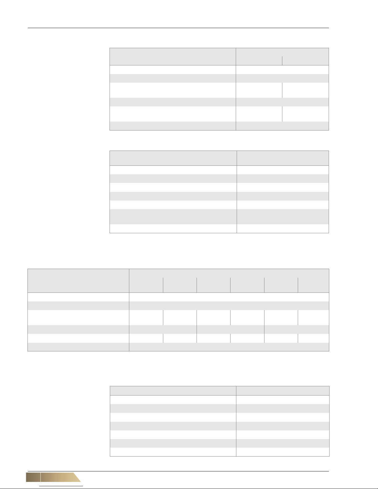
Fig. 2-4: Dimensions for unit type U with fan chamber (B, C) - GH##.U###.###B(C)#
Model size 1 2 3 4
b [mm] 560 865 1170 1590
Tab. 2-9: Widths dependent on unit size
Technical Description HyPower-Geko
16 FläktGroup DC-2014-0022-GB 2018-05/R5 • Subject to modifications
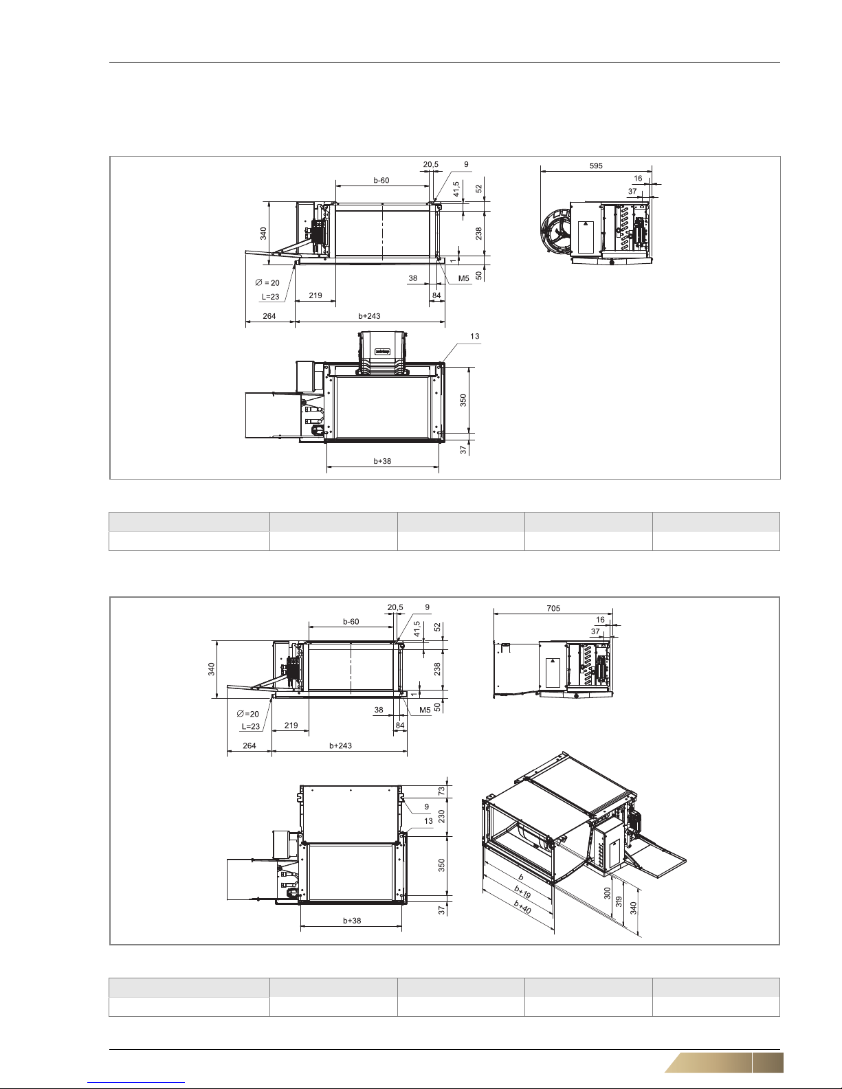
2.4.2 Air side accessories
Fig. 2-5: Dimensions for unit type H with fan chamber (B, C) - GH##.H###.###B(C)#
Model size 1 2 3 4
b [mm] 560 865 1170 1590
Tab. 2-10: Widths dependent on uni t size
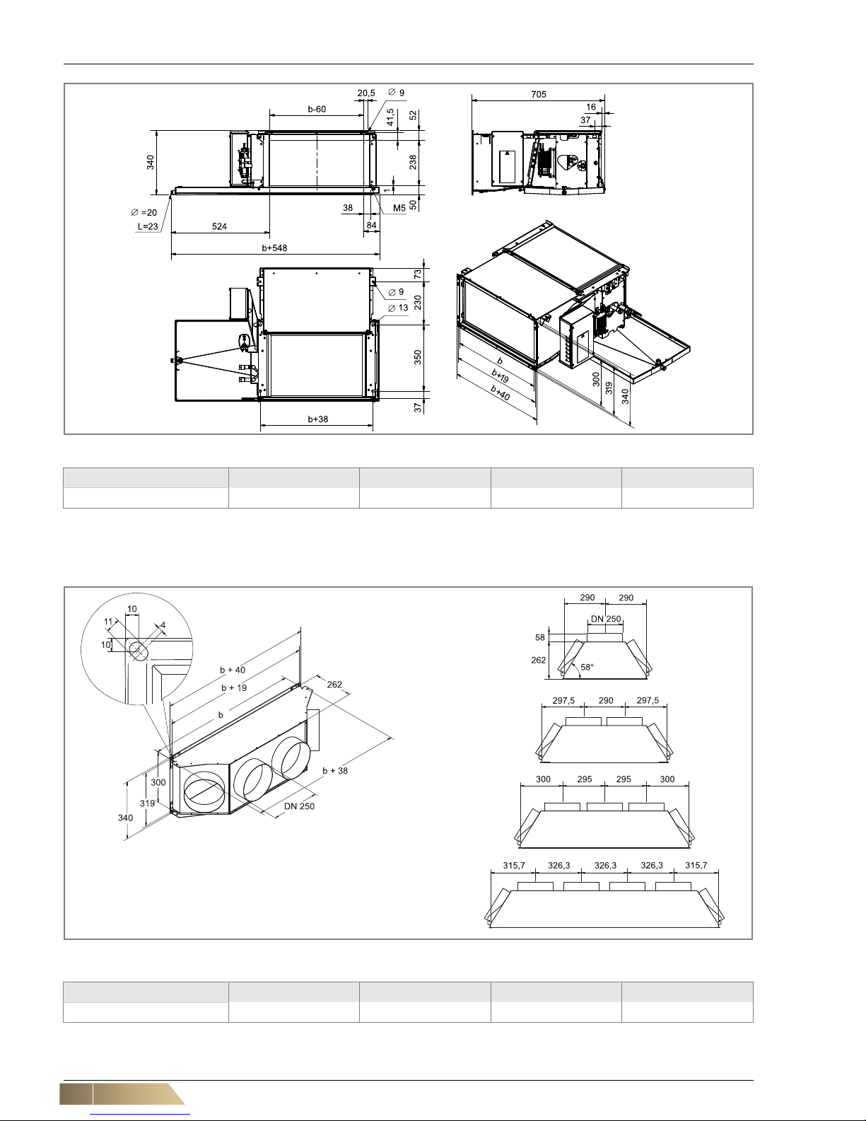
Fig. 2-6: Dimensions of intake and discharge plenum(ZGH.#A031 / ZGH.#A042)
Model size 1 2 3 4
b [mm] 560 865 1170 1590
Tab. 2-11: Unit size dependent width of accessories
HyPower-Geko Technical Description
FläktGroup DC-2014-0022-GB 2018-05/R5 • Subject to modifications 17
Fig. 2-7: Dimensions of intake and discharge plenum
(ZGH.#A111 / ZGH.#A112)
Fig. 2-10: Dimensions of air-intake and air-discharge sound
absorber fittings (ZGH.#A211 / ZGH.#A212)
Fig. 2-8: Dimensions air intake grille (intervention protection)
(ZGH.#A511)
Fig. 2-11: Dimensions of air discharge transition piece
(ZGH.#A912)
Fig. 2-9: Filter chamber, removal from top (ZGH.#A411) Fig. 2-12: Filter chamber, removal from side (ZGH.#A421)
Model size 1 2 3 4
b [mm] 560 865 1170 1590
Tab. 2-12: Unit size dependent width of accessor ies
Technical Description HyPower-Geko
18 FläktGroup DC-2014-0022-GB 2018-05/R5 • Subject to modifications
2.5 Unit data
2.5.1 Unit weight and water charge of heat exchanger
2.5.2 Air flow rate
2.5.3 Acustic values
Model size Weight1) [kg] Water charge[l]
2-pipe 4-pipe
Cooling circuit Heating circuit
VK A VK B VK C CS 1 CS 2 CS 3 CS 1 CS 2 CS 1 CS 2
1 27 33 36 1,2 2,2 3,3 1,7 2,2 0,7 1,2
2 37 45 48 1,7 3,3 4,8 2,5 3,3 0,9 1,7
3 48 59 62 2,2 4,3 6,4 3,2 4,3 1,2 2,2
4 60 75 79 2,9 5,8 8,5 4,3 5,8 1,6 2,9
1) Max. basic unit weight without accessories ... capacity stage VK .... Fan chamber
Tab. 2-13: Unit weight and water charge of heat excha nger
Model size
Air volume flow [m³/h] *)
AC motor (Min. / Max.) EC motor (Min. / Max.)
VK A VK B VK C VK A VK B VK C
1 700 / 1445 685 /1165 670 / 1090 505 / 1170 415 / 1095 415 / 1080
2 875 / 2640 845 / 2070 825 / 1725 740 / 2300 525 / 2110 500 / 1965
3 780 / 3200 720 / 2670 700 / 2565 1115 / 3460 815 / 3045 735 / 2745
4 2595 / 4490 2460 / 3740 2400 / 3440 1455 / 4540 970 / 4050 880 / 3695
*) at 0 Pa external pressure VK .... Fan chamber
Tab. 2-14: air volume flow
Model
size
Fan type
Sound power level
– intake-side [dB(A)]*)
Sound power level - discharge
side [dB(A)]*)
Sound power level - casing
radiation [dB(A)]*)
Min. / Max. Min. / Max. Min. / Max.
VK A VK B VK C VK A VK B VK C VK A VK B VK C
1
AC
52 / 68 56 / 67 55 / 64 50 / 67 55 / 67 56 / 66 - 48 / 59 49 / 57
2 49 / 70 50 / 68 49 / 65 48 / 68 50 / 68 50 / 67 - 47 / 60 47 / 58
3 46 / 72 44 / 69 41 / 67 44 / 72 44 / 70 44 / 70 - 41 / 61 42 / 61
4 63 / 74 65 / 71 63 / 69 61/74 63 / 74 64 / 72 - 59 / 63 56 / 61
1
EC
52 / 74 46 / 72 42 / 68 51 / 73 48 / 73 45 / 72 - 43 / 65 37 / 60
2 45 / 75 39 / 71 37 / 67 42 / 75 41 / 73 40 / 72 - 35 / 64 30 / 58
3 54 / 77 48 / 75 46 / 71 50 / 76 49 / 75 48 / 75 - 41 / 68 37 / 62
4 50 / 78 46 / 75 43 / 72 46 / 76 43 / 74 42 / 73 - 40 / 68 36 / 62
*) For control voltage 2-10V at 0 Pa external pressure (free intake and discharge)
VK .... Fan chamber
Tab. 2-15: Acoustic values of the basic unit
HyPower-Geko Technical Description
FläktGroup DC-2014-0022-GB 2018-05/R5 • Subject to modifications 19
2.5.4 Electrical data for fans
2.5.5 Electrical data of valve actuators
2.6 Condensate pump
In cooling units, condensate may form and is collected in the coil drip tray. If a slope
for condensate drainage is not fitted, a condensate pump must b e installed. This pump
drains condensate into drainage pipework located higher upstream.
2.6.1 Function of condensate drain
A separate level sensor is installed on the side of the unit at the condensate tray other than
the condensate pump, which performs the following functions:
– Start of the condensate pump when the condensate leve l exceeds 4 mm from the
bottom of the condensate tray.
– Switch-off of the condensate pump after the condensate is pumped out.
– Sends the signal ALARM if the maximum permitte d height of the conde nsate level
of 12 mm from the bottom of the condensate tray is exceeded.
Model size Fan type
Current consumption [A]*
)
Power consumption [W]*
)
Min. / Max. Min. / Max.
VK A VK B VK C VK A VK B VK C
1
AC
0.64 / 0.98 0.57 / 0.75 0.56 / 0.69 131 / 224 118 / 172 116 / 157
2 0.93 / 1.90 0.87 / 1.30 0.85 / 1.15 180 / 431 174 / 293 171 / 254
3 0.94 / 2.15 0.89 / 1.76 0.92 / 1.74 194 / 490 186 / 405 185 / 396
4 1.97 / 3.09 1.86 / 2.46 1.84 / 2.39 415 / 708 381 / 555 376 / 540
1
EC
0.13 / 1.54 0.11 / 1.47 0.11 / 1.44 20 / 213 18 / 212 16 / 206
2 0.18 / 2.09 0.16 / 2.10 0.15 / 2.07 17 / 296 13 / 300 11 / 288
3 0.30 / 3.43 0.26 / 3.47 0.23 / 3.47 33 / 510 27 / 485 26 / 471
4 0.29 / 3.76 0.26 / 3.98 0.23 / 3.83 30 / 591 25 / 573 23 / 541
*) For control voltage 2-10V at 0 Pa external pressure (free intake and discharge)
VK .... Fan chamber
Tab. 2-16: Electrical data for fans 230 V, 50 Hz
2- and 3-way valves
on/off control mode
(thermoelectric actuator)
2- and 3-way valves
modulating operation
(modulating actuator)
2- and 3-way valves
continuous operation
(continuous actuator)
Starting current
[A]
Operating
current [A]
Power
consumption
[W]
Current
consumption
[A]
Power
consumption
[W]
Current
consumption
[A]
Power
consumption
[W]
230 V 24 V 230 V 24 V 230 V 24 V 230 V 24 V 230 V 24 V 24 V 24 V
0,6 0,7 0,013 0,09 3 3 0,03 0,03 7 0,7 0,06 1,4
Tab. 2-17: Electrical data of valve actuators at 230 V, 50 Hz and 24 V, 50 Hz (and 0-10 V signal)
User instructions!
For fusing, observe the values specified in the connection diagram s (see Unknown
source of cross-reference, Unknown source of cross-reference).
Technical Description HyPower-Geko
20 FläktGroup DC-2014-0022-GB 2018-05/R5 • Subject to modifications
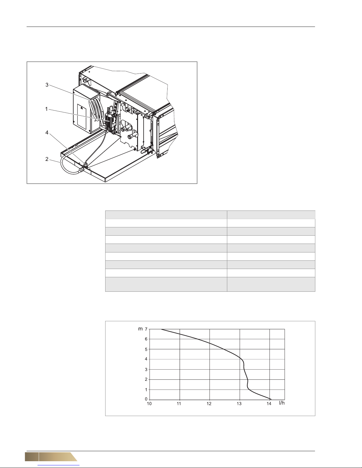
2.6.2 Technical data and capacity of condensate pump
The max. delivery head of the pump is 8 m, the maximum volume flow is 14 l/h. In the
fig. 2-14 the power of the pump is specified in l/h relative to the delivery head.
Technical data of condensate pump
Condensate pump capacity
Pos. 1: Condensate pump
Pos. 2: Suction hose with suction basket
Pos. 3: Pressure hose for on-site condensate
connection (1.5 m long)
Pos. 4: Fill level sensor with protective cover
Fig. 2-13: Condensate pump
Technical data Values
Operating voltage 230 V AC/50 Hz
Starting current max. 0.07 A
Operating current 0.02 A
Power input 4.7 W
Protection class IP64
Max. pump head 8 m
Max. water flow rate 14 l/h
Sound power level with H = 0 m 31 dB(A)
with H = 1 m 32 dB(A)
Tab. 2-18: Technical data of condensate pump
Fig. 2-14: Condensate pump capacity (pump head/volume)
Pump head [m]
Volume flow: [l/h]
HyPower-Geko Technical Description
FläktGroup DC-2014-0022-GB 2018-05/R5 • Subject to modifications 21
2.7 Air side accessories
The following accessories can be supplied for the HyPower-Geko fan coil unit:
Designation
Order No. Design
Flexible connection ZGH.#A112 discharge
ZGH.#A111 intake
Fire classification B1
Air intake box with round connector, not insulated
ZGH.#A031 Air intake plenum with round connectors DN 250, galvanized
sheet steel
Discharge plenum with round connector, insulated
ZGH.#A042 Discharge plenum with round spigot DN 250, galvanized sheet
steel with exterior sound and heat insulation
Seal cap for round connection, intake, insulated
ZGH.0A711 Made of galvanized sheet steel, to lock intake fitting DN 250.
Seal cap for round connector, discharge, insulated
ZGH.0A712 Made of galvanized sheet steel, to lock discharge fitting DN 250.
Filter chamber, removal from top ZGH.#A411 Galvanized metal sheet, module with removal of bag filter from
top
Filter chamber, removal from side ZGH.#A421 Galvanized metal sheet, module with removal of bag filter from
side
Sound absorber for
suction side assembly
ZGH.#A211 Galvanized sheet steel module with sound attenuating plates
Sound absorber for
pressure side assembly
ZGH.#A212 Galvanized sheet steel module with sound attenuating plates
Discharge transition piece, insulated
ZGH.#A912 Module made of galvanized sheet steel with exterior thermal in-
sulation
Contact protection ZGH.#A511 Galvanized sheet steel, for preventing contact with unit intake
opening, if no suction side accessories or on-site provided ducts
are connected.
Suspension rail 950 mm
1550 mm
2150 mm
ZGH.0A613
ZGH.0A623
ZGH.0A633
For quick mounting of basic unit and accessories with threaded
rods M8 and fixing material
Replacement filter
set
ZGH.#A823
ZGH.#A843
Synthetic-filter hose, filter quality
G2
(1 Set = 5 pieces)
Synthetic-filter hose, filter quality
G4
(1 Set = 5 pieces)
Tab. 2-19: Air side accessories HyPower-Geko
User instructions!
The symbol "#" is a placeholder for the size to be specified.
Technical Description HyPower-Geko
22 FläktGroup DC-2014-0022-GB 2018-05/R5 • Subject to modifications
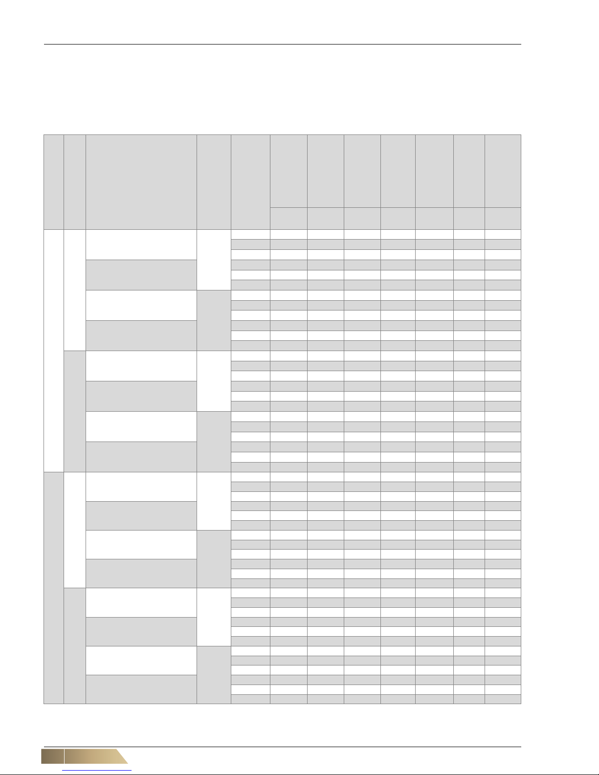
2.8 Commission Regulation (EU) 2016/2281 (Lot 30) November 2016
The values presented in the table Tab. 2-20 are provided to ensure the implementation
of the EU Directive 2009/125/EG. This Directive sets the framework for the requirements to the environmentally-friendly design of energy-related products such as air
heaters, air coolers, units for air cooling in industrial processes with high operating temperature and fan coil units.
Model size
Capacity stage
Units
Electric motor
Speed
Total cooling
capacity
Sensible
cooling capacity
Latent
cooling capacity
Heating capacity
Total power
consumption
Air flow rate
Sound power
level
P
rated,c
[kW]
P
rated,c
[kW]
P
rated,c
[kW]
P
rated,h
[kW]
P
elec
[kW]V[m3/h]
L
WA
[dB(A)]
1
1
GH11.#W0(0W, WC)#.
AC
1
3,1
2,8 0,3 3,7 0,121 710 55,0
3
3,9
3,6 0,3 4,6 0,141 955 61,0
5
4,3
3,9 0,4 5,1 0,157 1090 63,0
GH11.#WW#.
1
3,9
3,2 0,7 4,1 0,120 705 55,0
3
4,9
4,2 0,7 5,0 0,140 940 60,0
5
5,4
4,7 0,7 5,4 0,155 1065 63,0
GH11.#W0(0W, WC)#.
EC
1
2,1
1,9 0,2 2,5 0,017 430 44,0
3
3,4
3,1 0,3 4,1 0,089 815 60,0
5
4,2
3,9 0,3 5,1 0,205 1080 68,0
GH11.#WW#.
1
2,6
2,0 0,6 2,8 0,017 425 43,0
3
4,3
3,6 0,7 4,4 0,087 800 60,0
5
5,4
4,7 0,7 5,4 0,203 1065 58,0
2
GH12.#W0(0W, WC)#.
AC
1
4,5
3,5 1,0 5,0 0,120 705 55,0
3
5,7
4,5 1,2 6,4 0,140 940 60,0
5
6,3
5,1 1,2 7,2 0,155 1065 63,0
GH12.#WW#.
1
4,3
3,4 0,9 6,4 0,118 685 55,0
3
5,4
4,3 1,1 7,8 0,135 890 60,0
5
5,9
4,7 1,2 8,5 0,150 990 62,0
GH12.#W0(0W, WC)#.
EC
1
2,9
2,2 0,7 3,2 0,017 425 43,0
3
5,0
3,9 1,1 5,6 0,087 800 60,0
5
6,3
5,1 1,2 7,2 0,203 1065 68,0
GH12.#WW#.
1
2,8
2,1 0,7 4,2 0,016 405 43,0
3
4,7
3,7 1,0 6,9 0,082 760 59,0
5
6,2
4,9 1,3 8,8 0,205 1035 68,0
2
1
GH21.#W0(0W, WC)#.
AC
1 3,9 3,5 0,4 4,6 0,176 840 49,0
3 5,9 5,4 0,5 7,1 0,231 1460 61,0
5 6,7 6,2 0,5 8,1 0,254 1725 65,0
GH21.#WW#.
1 4,6 3,8 0,8 3,4 0,174 835 50,0
3 7,0 6,2 0,8 6,7 0,288 1410 61,0
5 7,9 7,1 0,8 8,9 0,094 1645 64,0
GH21.#W0(0W, WC)#.
EC
1 2,9 2,6 0,3 3,4 0,012 585 37,0
3 5,6 5,2 0,4 6,7 0,094 1360 57,0
5 7,4 6,8 0,6 8,9 0,288 1965 67,0
GH21.#WW#.
1 3,3 2,6 0,7 3,9 0,012 555 37,0
3 6,6 5,7 0,9 7,1 0,091 1295 57,0
5 8,9 8,0 0,9 9,2 0,281 1900 67,0
2
GH22.#W0(0W, WC)#.
AC
1 5,5 4,2 1,3 6,1 0,174 835 50,0
3 8,6 6,8 1,8 9,7 0,223 1410 61,0
5 9,8 7,9 1,9 11,2 0,246 1645 64,0
GH22.#WW#.
1 5,5 4,2 1,3 8,1 0,173 830 50,0
3 8,3 6,6 1,7 11,9 0,215 1350 61,0
5 9,4 7,4 2,0 13,3 0,236 1550 64,0
GH22.#W0(0W, WC)#.
EC
1 3,9 2,9 1,0 4,2 0,012 555 37,0
3 8,0 6,3 1,7 9,0 0,091 1295 57,0
5 11,1 9,0 2,1 12,6 0,281 1900 67,0
GH22.#WW#.
1 3,7 2,7 1,0 5,5 0,012 520 37,0
3 7,6 6,0 1,6 11,0 0,088 1220 57,0
5 10,7 8,6 2,1 15,0 0,272 1815 66,0
HyPower-Geko Technical Description
FläktGroup DC-2014-0022-GB 2018-05/R5 • Subject to modifications 23
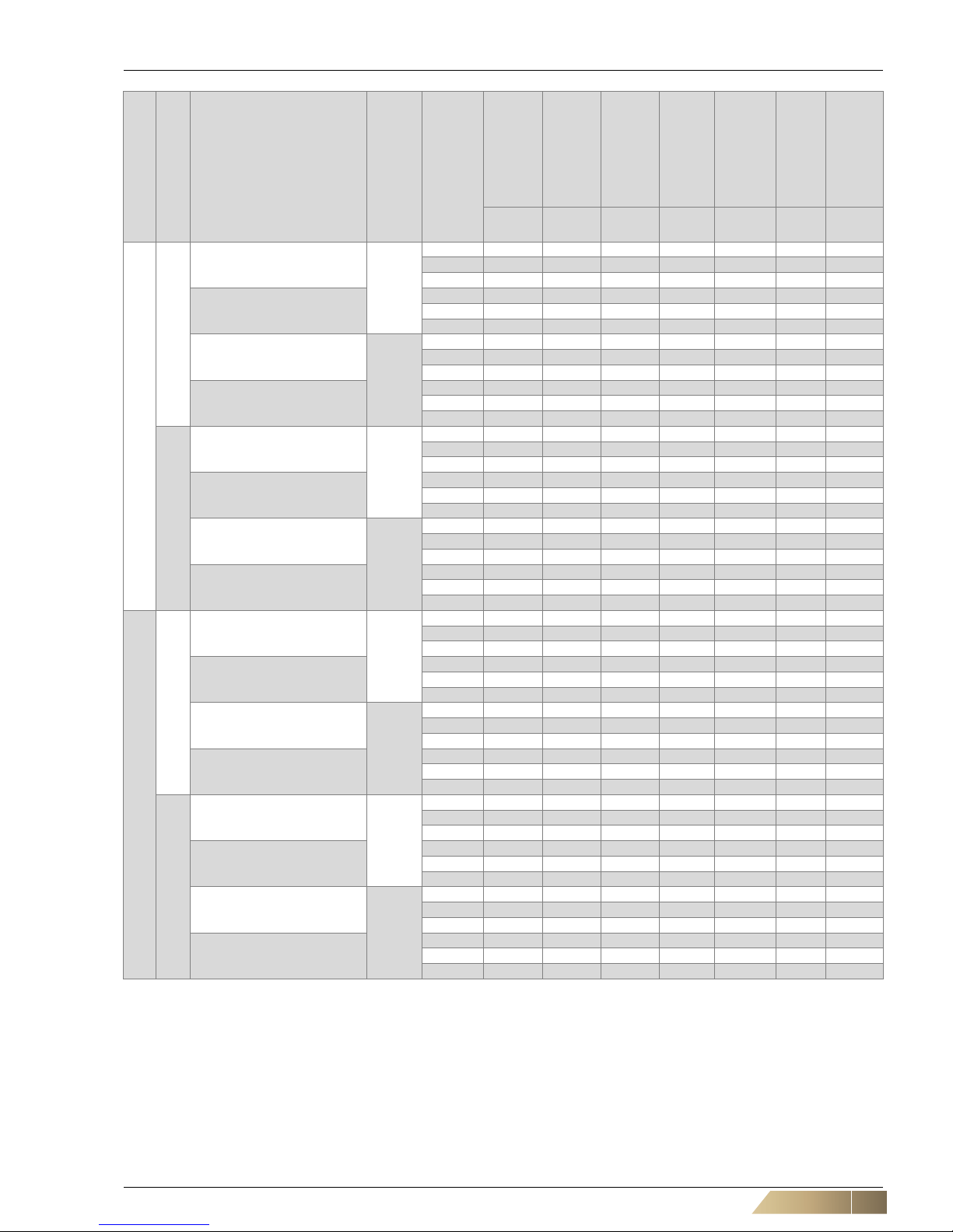
Tab. 2-20: Values according to the EU Directive 2016/2281
Specified values are valid for:
2-pipe systems - heating capacity with pumped warm water temperature 45/40°C, air inlet temperature +20°C./ rel. hu midity 50%, cooling capacity with pumped chilled water temperature 7/12°C, air inlet temperature +27°C./ rel. humidity
50%
4-pipe systems - heating capacity with pumped warm water temperature 65/55°C, air inlet temperature +20°C./ rel. hu midity 50% and for cooling capacity with pumped chilled water 7/12°C, air inlet temperature 27°C, rel. humidity 50%
Units are equipped with G2 filter.
3
1
GH31.#W0(0W, WC)#.
AC
1 3,7 3,2 0,5 4,3 0,185 715 41,0
3 6,7 6,1 0,6 8,0 0,303 1555 57,0
5 9,8 9,1 0,7 11,8 0,396 2565 67,0
GH31.#WW#.
1 4,5 3,5 1,0 5,0 0,185 710 42,0
3 8,5 7,1 1,4 8,7 0,298 1540 57,0
5 12,3 10,8 1,5 12,1 0,383 2455 66,0
GH31.#W0(0W, WC)#.
EC
1 4,2 3,7 0,5 4,9 0,027 840 46,0
3 8,0 7,4 0,6 9,6 0,187 1965 64,0
5 10,3 9,5 0,8 12,4 0,471 2745 71,0
GH31.#WW#.
1 4,9 3,9 1,0 5,5 0,026 800 46,0
3 9,8 8,3 1,5 9,9 0,181 1845 63,0
5 13,0 11,4 1,6 12,7 0,459 2615 71,0
2
GH32.#W0(0W, WC)#.
AC
1 5,0 3,7 1,3 5,4 0,185 710 42,0
3 9,8 7,6 2,2 10,9 0,298 1540 57,0
5 14,5 11,7 2,8 16,5 0,383 2455 66,0
GH32.#WW#.
1 5,0 3,7 1,3 7,6 0,185 705 43,0
3 9,7 7,6 2,1 14,1 0,295 1530 57,0
5 14,0 11,2 2,8 19,7 0,371 2345 66,0
GH32.#W0(0W, WC)#.
EC
1 5,6 4,1 1,5 6,0 0,026 800 46,0
3 11,4 9,0 2,4 12,8 0,181 1845 63,0
5 15,3 12,4 2,9 17,4 0,459 2615 71,0
GH32.#WW#.
1 5,3 3,9 1,4 8,1 0,026 760 46,0
3 10,9 8,5 2,4 15,6 0,175 1740 63,0
5 14,7 11,9 2,8 20,6 0,450 2500 70,0
4
1
GH41.#W0(0W, WC)#.
AC
1 10,9 10,0 0,9 12,9 0,410 2585 63,0
3 12,5 11,5 1,0 14,8 0,472 3105 66,0
5 13,4 12,4 1,0 16,0 0,540 3440 69,0
GH41.#WW#.
1 13,6 11,5 2,1 13,5 0,400 2530 63,0
3 15,7 13,4 2,3 15,3 0,456 3005 66,0
5 17,0 14,7 2,3 16,4 0,525 3325 69,0
GH41.#W0(0W, WC)#.
EC
1 5,2 4,4 0,8 6,0 0,023 995 43,0
3 10,5 9,6 0,9 12,5 0,171 2480 63,0
5 14,2 13,1 1,1 16,9 0,541 3695 72,0
GH41.#WW#.
1 6,1 4,7 1,4 6,7 0,023 955 43,0
3 12,9 10,8 2,1 12,9 0,164 2355 63,0
5 18,0 15,7 2,3 17,2 0,532 3580 72,0
2
GH42.#W0(0W, WC)#.
AC
1 15,8 12,4 3,4 17,7 0,400 2530 63,0
3 18,3 14,5 3,8 20,6 0,456 3005 66,0
5 19,9 15,9 4,0 22,5 0,525 3325 69,0
GH42.#WW#.
1 15,4 12,0 3,4 21,9 0,386 2455 63,0
3 17,6 13,9 3,7 24,7 0,436 2870 66,0
5 19,1 15,1 4,0 26,5 0,505 3155 68,0
GH42.#W0(0W, WC)#.
EC
1 6,8 5,0 1,8 7,3 0,023 955 43,0
3 14,9 11,6 3,3 16,6 0,164 2355 63,0
5 21,2 17,0 4,2 24,0 0,532 3580 72,0
GH42.#WW#.
1 6,5 4,8 1,7 9,9 0,023 910 43,0
3 14,1 10,9 3,2 20,2 0,157 2215 62,0
5 20,4 16,3 4,1 28,2 0,518 3425 72,0
Model size
Capacity stage
Units
Electric motor
Speed
Total cooling
capacity
Sensible
cooling capacity
Latent
cooling capacity
Heating capacity
Total power
consumption
Air flow rate
Sound power
level
P
rated,c
[kW]
P
rated,c
[kW]
P
rated,c
[kW]
P
rated,h
[kW]
P
elec
[kW]V[m3/h]
L
WA
[dB(A)]
Shipping and storage HyPower-Geko
24 FläktGroup DC-2014-0022-GB 2018-05/R5 • Subject to modifications
3 Shipping and storage
3.1 Transport safety
3.2 Packaged content
Remove packing and inspect shipment immediately upon receipt to determine if any
damage has occurred to the unit during shipment (if any damage is found, immediately
file claim for damage with the transportation company), also check for missing items
and verify that the shipment is complete. For this purpose compare the details of the
unit type plate with the information on the dispatch note .
The same applies to all accessory items. Missing parts or claims of shipping damage
must only be reported to the transport insurance, if the da mage has been confirmed by
the delivering carrier.
3.3 Packaging
The unit is packed on a pallet in a carton with reinforcements that permits stacking
(max. 2 pieces). The accessories are packaged individually in cartons and fastened to
the carton of the unit. Everything is wrapped with a protective foil.
3.4 Transport
Danger due to overhead loads!
It is extremely dangerous to stand under overhead loads.
• Make sure there are no persons below an overhead load!
Risk of damage to the unit!
Improper shipping can cause damage to the fan coil unit.
• If damage has been caused by impacts to the unit or by dropping it, carefully
check that the fan coil unit is working properly.
• Take care when transporting the fan coil unit!
DAMAGE TO UNIT AND PERSONAL INJURY
• Always wear protective gloves to prevent injury caused by sharp edges.
• To prevent injury ensure that at least two people carry the HyPower-Geko.
• When delivering on pallets, use only lifting gear and transport vehicles with suf-
ficient load-bearing capacity.
• Secure the load during transit to prevent it from tipping or falling.
HyPower-Geko Shipping and storage
FläktGroup DC-2014-0022-GB 2018-05/R5 • Subject to modifications 25
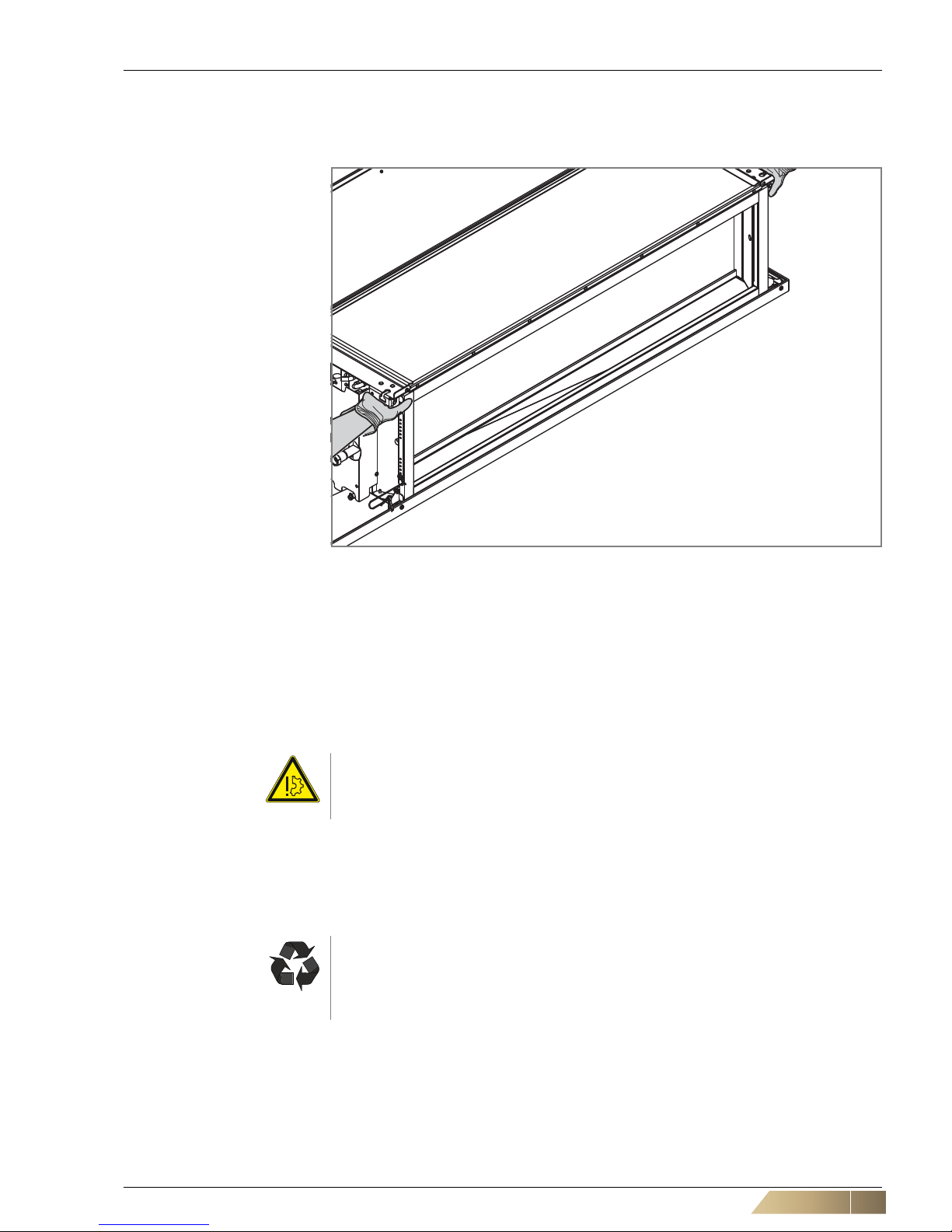
Horizontal transport
The HyPower-Geko must only be transported and lifted on both side s of bottom edges
(refer to
fig. 3-1).
3.5 Temporary storage
When storing the unit for a temporary period, the following aspects must be considered:
– Store the fan coil unit in its original packing.
– The storage location must be protected from the elements, dry and dust-free with
relative humidity between 50% and 85%. The storage temperature must be
between -10 to +50 °C.
– The fan coil unit must be protected from impacts, vibrations, etc.
– Protect the unit from soiling before and during installation
3.6 Disposal
During disposal, the units components must be separated as far is possible and sorted
by material type (refer to
"Material specification" on page 12).
Fig. 3-1: Transport
Risk of damage to the unit!
All residual water must be drained from the heat exchanger!
Frost risk!
Recycling
Ensure that operating supplies, packaging and replacement parts are disposed of
in a safe and environmentally friendly manner. Use the local recycling facilities and
observe all pertinent local regulations and codes.
Mounting HyPower-Geko
26 FläktGroup DC-2014-0022-GB 2018-05/R5 • Subject to modifications
4 Mounting
4.1 Installation site
Type, condition and ambient temperature of the installation site must be suitable for the
relevant fan coil unit (refer to
Chapter 1.6 and Chapter 1.7). Consider the following
points:
– Only indoor mounting of the unit is allowed.
– Ceiling or mounting systems must be capable of bearing the weight of the unit,
including all accessories.
– Consider the appropriate fixing material (screws/bolts, plugs, etc.) th at co rr es po nd
with total unit weight and characteristics of suspension points.
Danger of electrical current!
Before drilling, ensure that the drilling area is free from electrical cables and pipes.
Risk of personal injury!
Injury may be caused by falling parts and sharp edges!
Wear a helmet, safety boots and protective gloves when installing the unit. Ceiling
installations should always be performed by two persons.
Personal injury and hazardous voltage!
If the HyPower basic unit is operated without FläktGroup accessories or on-site
accessories provided by others or ductwork on air intake side - an appropriate con
tact protection must be provided at the unit air intake! In this case use a contact protection (accessory order-Nr ZGH.#A511, where „#“ is reserved for unit size).
User instructions!
It must be ensured that no mechanical deformations or twisting occurs when installing units in different positions and configurations.
User instructions!
Make sure all wall and ceiling openings are completed in coordination with an architect or static engineer and the building contractor.
HyPower-Geko Mounting
FläktGroup DC-2014-0022-GB 2018-05/R5 • Subject to modifications 27
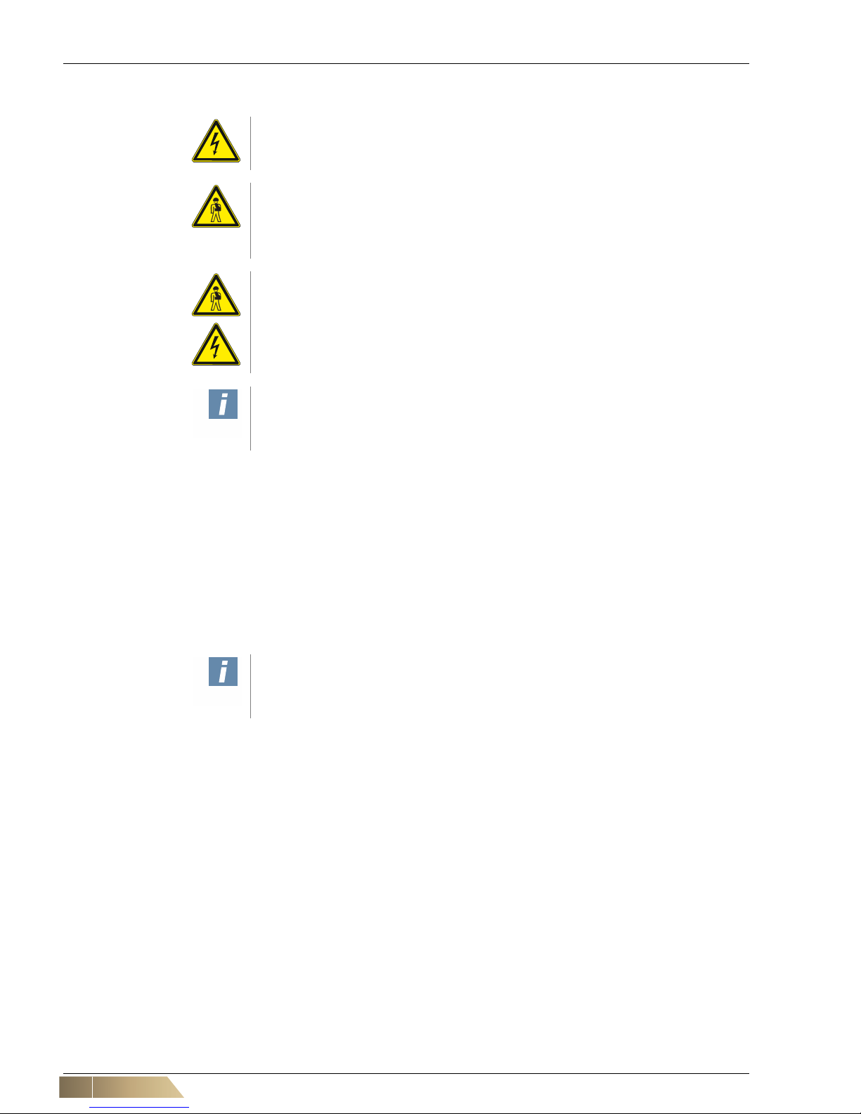
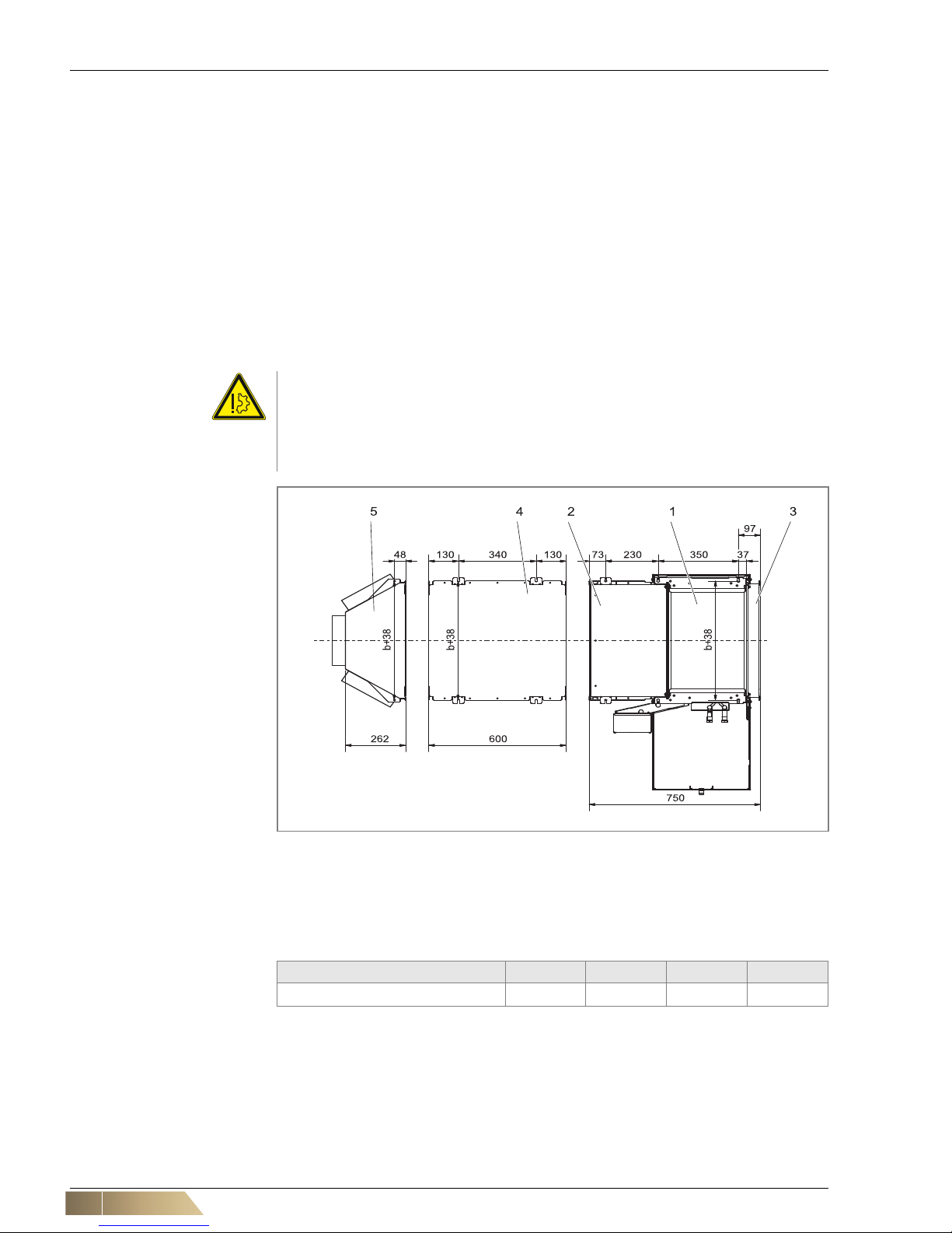
4.2 Recommended service opening for maintenance work on the basic unit
4.2.1 Unit type U (GH##.U###.#####)
In order to carry out all necessary service and maintenance work on the basic unit it is
recommended that a service opening with minimum dimensions of B x 1150 mm (B
x
1040 mm)* is provided (see
fig. 4-1).
Pos. 1: Condensate tray - small - unit type U
Pos. 2: Service panel
Pos. 3: Filter behind cover strip
Pos. 4: Discharge transition piece (ZGH.#A912)
Pos. 5: Auxiliary drain pan
Fig. 4-1: Service opening - unit type U (GH##.U###.#####)
*) Dimensions in brackets apply to units without fan chamber
**) Dimensions in brackets apply if an auxiliary drain pan is used
Model size 1 2 3 4
b [mm] 560 865 1170 1590
b
max
[mm]*** 805 1110 1415 1835
B [mm]*** 1265 (1565)** 1570 (1870)** 1875 (2175)** 2295 (2595)**
Tab. 4-1: Size of unit type U (GH##.U###.#####) and service opening
***)
Dimensions also apply for units with function "only heating"
User instructions!
Please consider that further or larger openings may be needed, if accessories are
mounted.
Mounting HyPower-Geko
28 FläktGroup DC-2014-0022-GB 2018-05/R5 • Subject to modifications
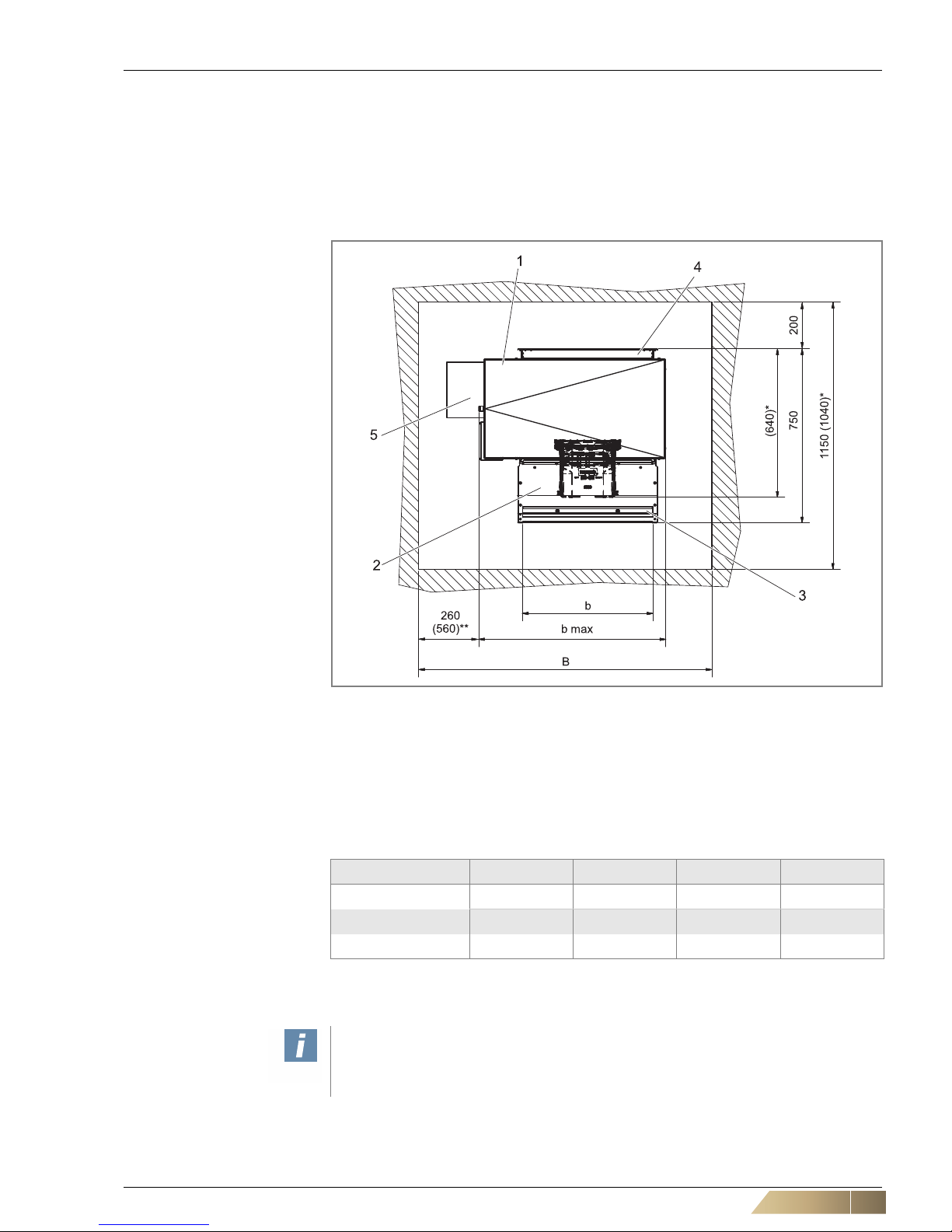
4.2.2 Unit type H (GH##.H###.#####)
In order to carry out all necessary service and maintenance work on the basic unit it is
recommended that a service opening with minimum dimensions of B x 1150 mm (B
x
1040 mm)* is provided (see
fig. 4-2 )
Pos. 1: Condensate tray - large - unit type H
Pos. 2: Service panel
Pos. 3: Filter behind cover strip
Pos. 4: Discharge transition piece (ZGH.#A912)
Fig. 4-2: Service opening - unit type H (GH##.H###.#####)
*) Dimensions in brackets apply to units without fan chamber
Model size 1 2 3 4
b [mm] 560 865 1170 1590
b
max
[mm] 1110 (805)** 1415 (1110)** 1720 (1415)** 2140 (1835)**
B [mm] 1560 (1265)** 1860 (1570)** 2160 (1875)** 2590 (2295)**
Tab. 4-2: Size of unit type H (GH##.U###.#####) and service opening
**) Dimensions in brackets also apply for units with function "only heating"
User instructions!
Please consider that further or larger openings may be needed, if accessories are
mounted.
HyPower-Geko Mounting
FläktGroup DC-2014-0022-GB 2018-05/R5 • Subject to modifications 29
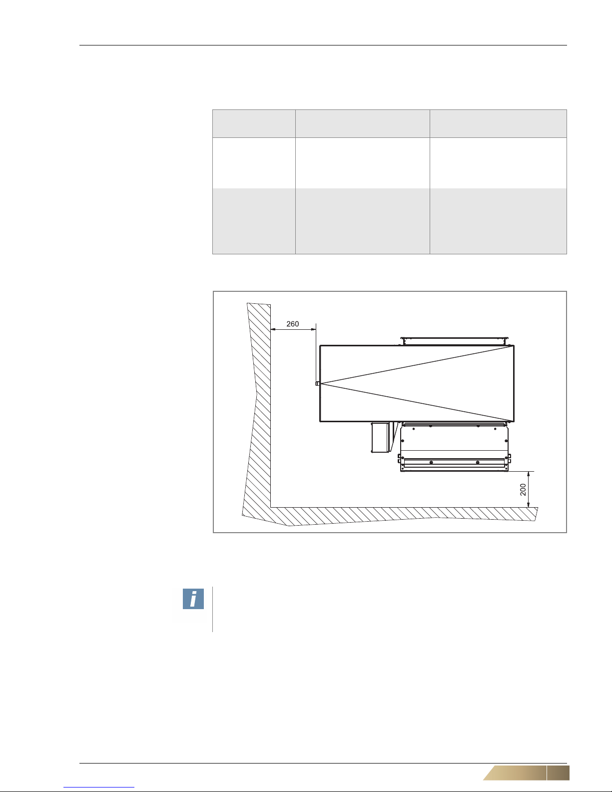
4.3 Pre-installation work
Depending on the connection side, the pipes can be connected from the left or from
the right. The following installation clearances must be observed:
Position No.,
refer to fig. 4-3
REASON Installation
clearance [mm]
1
for proper inflow of the air from
the back (does not apply if
connected to an on-site intake
duct)
to the back
200
2
for installation work, e.g. for
lateral connection to the onsite valve piping
to the side
260
without valve accessories
560
with valve accessories
Tab. 4-3: Installation clearances
Fig. 4-3: Assembly spacing (viewing from below)
*) Dimensions in brackets apply to valve accessories for assembly of factory valve
equipment
1
2
User instructions!
The spacing between unit top edge and room ceiling should be at least 50 mm.
Mounting HyPower-Geko
30 FläktGroup DC-2014-0022-GB 2018-05/R5 • Subject to modifications
4.4 Unit mounting
4.4.1 Installation with various fixing materials
To fasten the units, assembly mountings with 2 holes are provided (1 on each side, see
fig. 4-6, Pos. 1). Appropriate fixing accessories are needed dependin g on the mounting
variant (refer to fig. 4-5).
For mounting on the room ceiling, at least 2 holes (intake/discharge plenum, 1 on each
side) or 4 holes (basic unit or intake/discharge sound attenuator, 2 on each side) are
required.
The position of the holes of the assembly mountings is presented in thefig. 4-4. The
spacing of the holes of the assembly mountings correspond exactly to the spacing of
the assembly holes in the room ceiling, for the basic unit as well as the assemblies of
the accessory.
Risk of damage to the unit!
The unit must be mounted in such a way to ensure unobstructed air flow in subsequent operation.
The clearance between unit top line and the room ceiling should amount to at least
50 mm.
Fig. 4-4: Hole spacing of the assembly mountings
Pos. 1: Basic unit
Pos. 2: Fan chamber
Pos. 3: Discharge transition piece
Pos. 4: Intake/discharge sound attenuator
Pos. 5: Intake/discharge plenum
Model size 1 2 3 4
b [mm] 560 865 1170 1590
Tab. 4-4: Unit size dependent width of accessories
 Loading...