

FläktGroup ECO SIDE Installation And Maintenance Manual
INSTALLATION AND MAINTENANCE MANUAL
ECO SIDE

eCO Side - Installation and Maintenance Manual
2
FläktGroup DC_10176GB_20180924_R3 Specifications are subject to alteration without notice
Page
1. SAFETY INSTRUCTIONS ................................................................................3
VDI 6022 ............................................................................................................3
2. DESCRIPTION OG THE UNIT .......................................................................... 4
3. TRANSPORT AND PLACEMENT ..................................................................5
4. CONNECTIONS
4.1 Duct connections .....................................................................................6
4.2 Post heater, electrical (9 kW) .............................................................6
4.3 Post heater, hot water ...........................................................................6
4.4 Cooling coil, water ...................................................................................7
4.5 Valve and valve actuator ...................................................................... 7
4.6 Damper ........................................................................................................ 7
4.7 Silencer ........................................................................................................ 7
5. ELECTRICAL CONNECTIONS
5.1 Fuse protection ........................................................................................8
5.2 Electrical data...........................................................................................8
5.3 Main supply ...............................................................................................8
5.4 Connection of control panel ................................................................9
6. CONNECTION OF EXTERNAL COMPONENTS
6.1 Electrical post heater (Size 06, 9 kW) .........................................10
6.2 Post heater, hot water .........................................................................10
6.3 Cooling coil, water ................................................................................10
6.4 Cooling coil, DX ......................................................................................10
6.5 Damper .....................................................................................................10
6.6 Temperature sensors ...........................................................................11
6.7 Extended / Forced ventilation ..........................................................11
6.8 Fire protection function .......................................................................11
6.9 Summary alarm .....................................................................................11
7. WIRING DIAGRAMS ...............................................................................12
8. TESTING OF FUNCTIONS.......................................................................15
9. CONTROL PANEL, OPEERATIONS, COMMISSIONING
9.1 General .......................................................................................................16
9.2 Home screen overview ......................................................................17
9.3 Sub menus ..............................................................................................19
9.4 Date/time, language ...........................................................................20
9.5 Advanced settings for installers and sevice personnel ..........21
9.6 Commissioning Wizard .....................................................................22
9.7 Schedules ................................................................................................ 26
Page
10. CONTROL FUNCTIONS
10.1 Rotor, heating and cooling .............................................................29
10.2 Temperature controls ......................................................................29
10.3 Freeze protection ...............................................................................31
10.4 Defrost function ...................................................................................31
10.5 Cooling recovery ................................................................................31
10.6 Night cooling ........................................................................................31
10.7
Pressure or Constant flow control .......................................32
11. COMMUNICATION
11.1 Modbus, RS485 ...................................................................................33
11.2 Modbus, TCP/IP .................................................................................33
11.3 Webserver ............................................................................................33
12. PARAMETER LIST ........................................................................................ 34
13. MAINTENANCE
13.1 General ...................................................................................................40
13.2 Filter........................................................................................................ 40
13.3 Rotary Heat Exchanger ................................................................... 41
13.4 Post heater, hot water ..................................................................... 42
13.5 Post heater, electrical .................................................................... 43
13.6 Cooling coil, water ............................................................................ 43
13.7 Fans ........................................................................................................ 44
13.8 Service schedule .............................................................................. 45
14. DECLARATION OF CONFORMITY ............................................................46
15. DISPOSAL ....................................................................................................... 47
CONTENTS
eCO Side - Installation and Maintenance Manual
3
FläktGroup DC_10176GB_20180924_R3 Specifications are subject to alteration without notice
OPERATION OF AIR HANDLING UNITS
AND ACCESSORIES
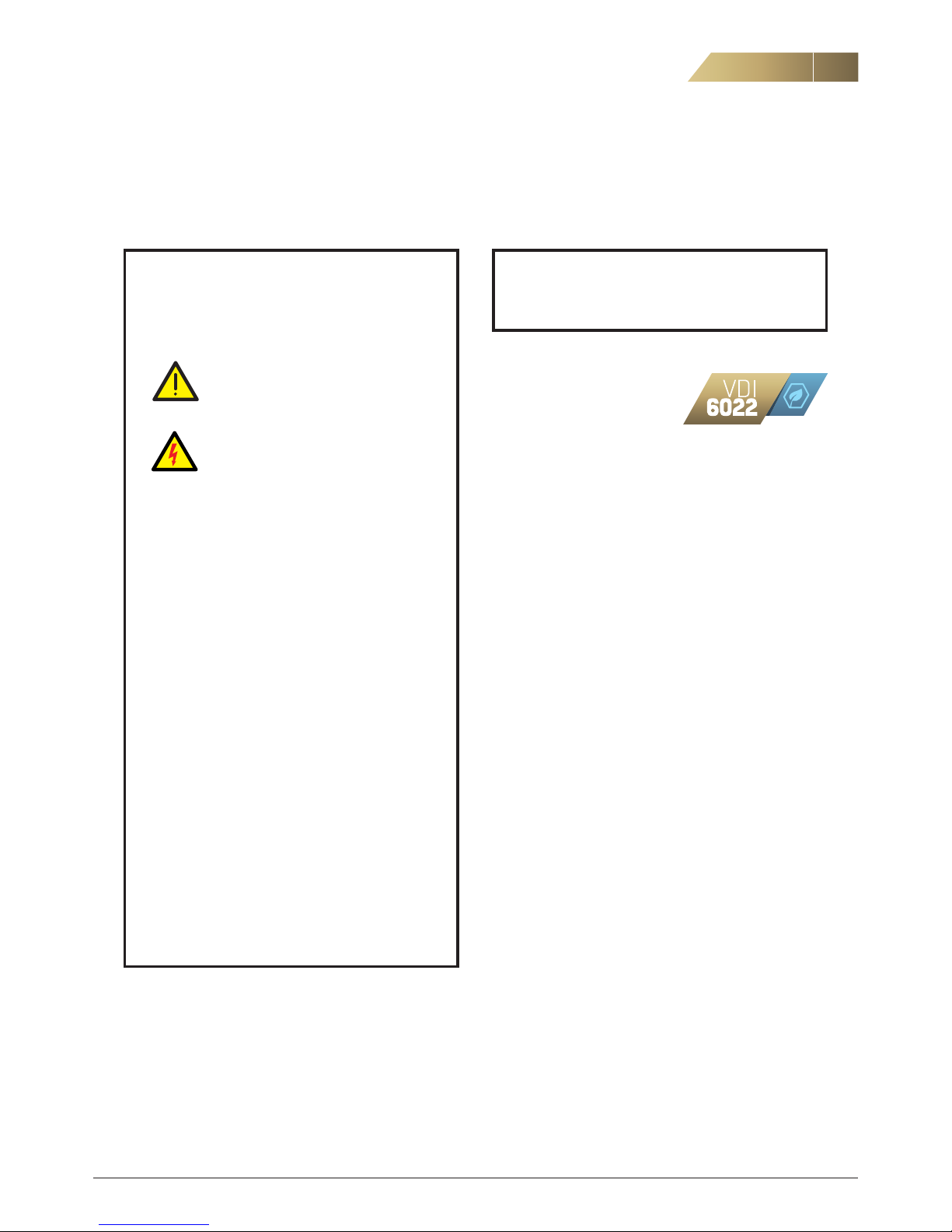
WARNING
Before taking the air handling unit into
operation fit any unused connections with
protective mesh.
In addition, all electrotechnical and me
chanical safety devices must be
installed before taking the air handling
unit into operation.
– Before opening the unit check that its power has been
disconnected.
– Take care when opening the isolating valves for the hot
water to the air heater. There is a risk of water hammer
or steam discharge.
– When servicing or inspecting the unit, turn off the
safety switch before opening the inspection doors.
Reset all safety devices before restarting.
– The clearance in front of electric heaters and electrical
cabinets shall conform to applicable electrical safety
regulations.
– Use the control panel to stop the unit.
– The unit’s hatches are fitted with locking handles.
Ensure that the unit is always left locked, and that the
keys cannot be accessed by unauthorized persons.
– Do not open inspection hatches when the unit is in
operation.
– Use protective gloves during installation and service.
1. SAFETY INSTRUCTIONS
Installation may only be
carried out by qualified personnel.
VDI 6022
eCO Side is designed in accordance to hygiene standard VDI 6022
and is easy to clean with no place where dirt can accumulate.
Nonmetallic part, have been chosen as proven free of micro bac
-
terial or mold growth.
Following the VDI 6022, AHU should ensure a physiologically
favourable indoor climate and a hygienically perfect indoor air
quality.
The eCO Side is designed in order, not to endanger health, not to
disturb the condition and the thermal comfort, not to lead to odour
nuisance and to prevent exposure and impact of inorganic and
organic pollutants.
eCO Side - Installation and Maintenance Manual
4
FläktGroup DC_10176GB_20180924_R3 Specifications are subject to alteration without notice
FANS
The unit has two plug fans with EC motors.
ROTARY HEAT EXCHANGER
The speed controlled rotor is fitted with a purge sector and a rotation sensor.
CONTROL SYSTEM
The ISYteq Mini control system is integrated with the unit and is
ready for use with a large number of functions.
COMPONENTS
The unit can be supplied in left-hand or right-hand configurations.
Left-hand configurations is mirror-reversed to right-hand. Refer to
the order code in Technical Instruction.
2. DESCRIPTION OF THE UNIT
FILTER
Bag filter class (F7) ePM1 50% on both supply and extract air.
POST HEATER, HOT WATER
Hot water coil containing copper tubes and aluminum fins. Pipe
connection ø15 mm. Freeze protection temperature sensor is
included. Max operating pressure 3.0 MPa.
POST HEATER, ELECTRICAL
The heater for size 03 and 04 is built-in. For size 06 the heater is
duct mounted.
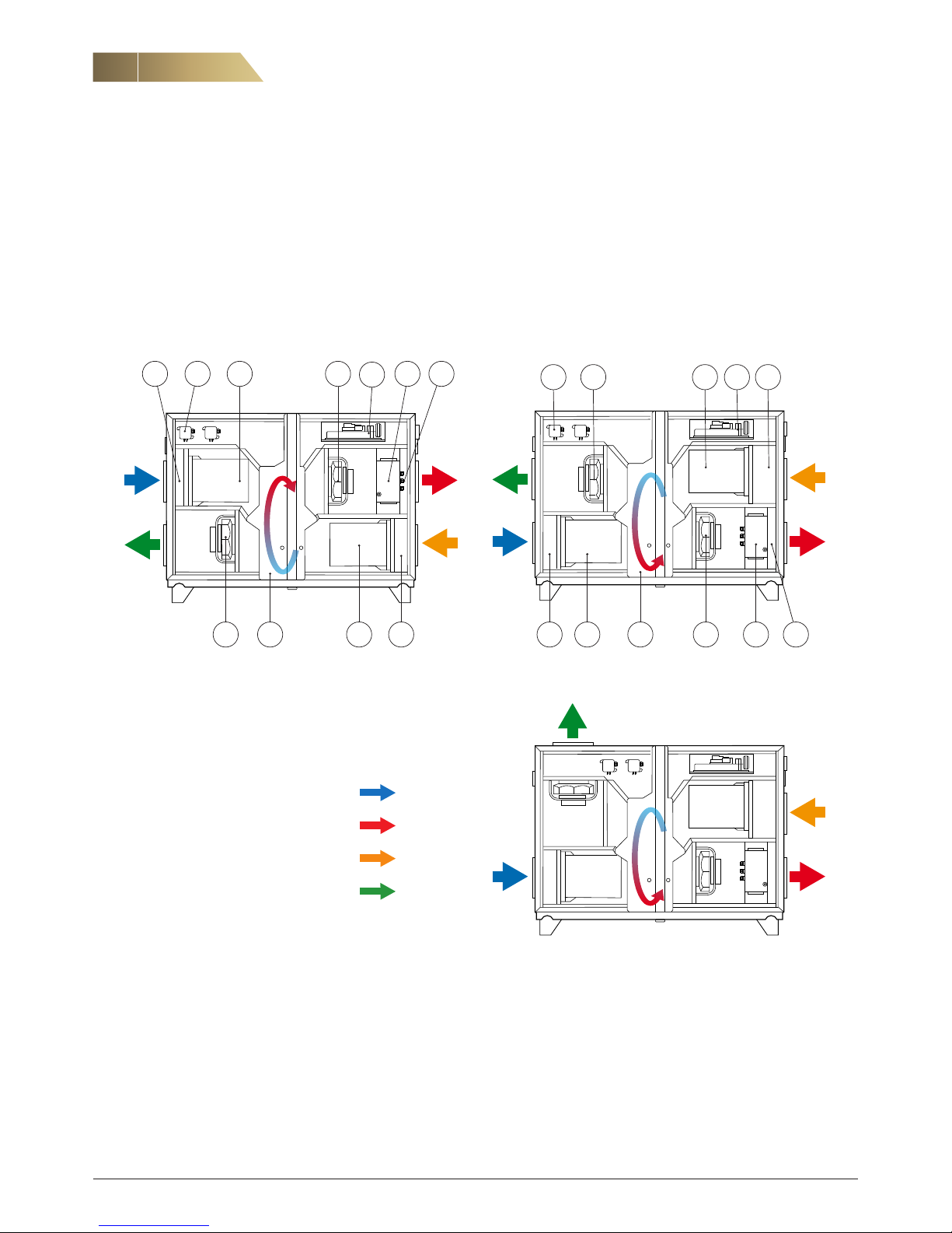
TOP RIGHT HAND CONFIGURATION RDSP, bb = 12 or 14 BOTTOM RIGHT-HAND CONFIGURATION RDSP, bb = 11 or 13
EXHAUST AIR UPWARDS RDSP, bb = 11 or 13 and c = 2
1 Outdoor air sensor GT3
2 Supply filter
3 Rotary heat exchanger with rotation sensor
4 Supply fan
5 Electrical heater including overheating
protection alternativelyhot water coil
with freeze protection GT5
6 Supply air sensor GT1
7 Extract air sensor GT12
8 Control equipment
9 Extract filter
10 Exhaust fan
11 Pressure guard
Outdoor air
Supply air
Extract air
Exhaust air
3 4 5 61 2
1011 8 79
64
8
5
3 79
10
1 211
eCO Side - Installation and Maintenance Manual
5
FläktGroup DC_10176GB_20180924_R3 Specifications are subject to alteration without notice
SOUND TRANSMISSION
When a unit is positioned next to a wall, low frequency sound can
generate vibrations in the wall, even if the sound level from the
unit is acceptable. Generally the unit should be positioned against
a wall adYescent to a room that is not sensitive for noise. When
this is not possible the unit should be positioned 400-500 mm
from the wall.
Duct lead-through must be designed with care so that rigid
connections between the duct and wall do not occur. In addition,
the seal around the duct must be carefully installed to prevent
the transmission of noise to adYescent areas. For sensitive in
stallations it may be a good idea to connect ducts using flexible
connections.
If the floor structure is weak, noise can be transmitted to other
areas in the building. Use of a heavy insulating mat can prevent
that problem.
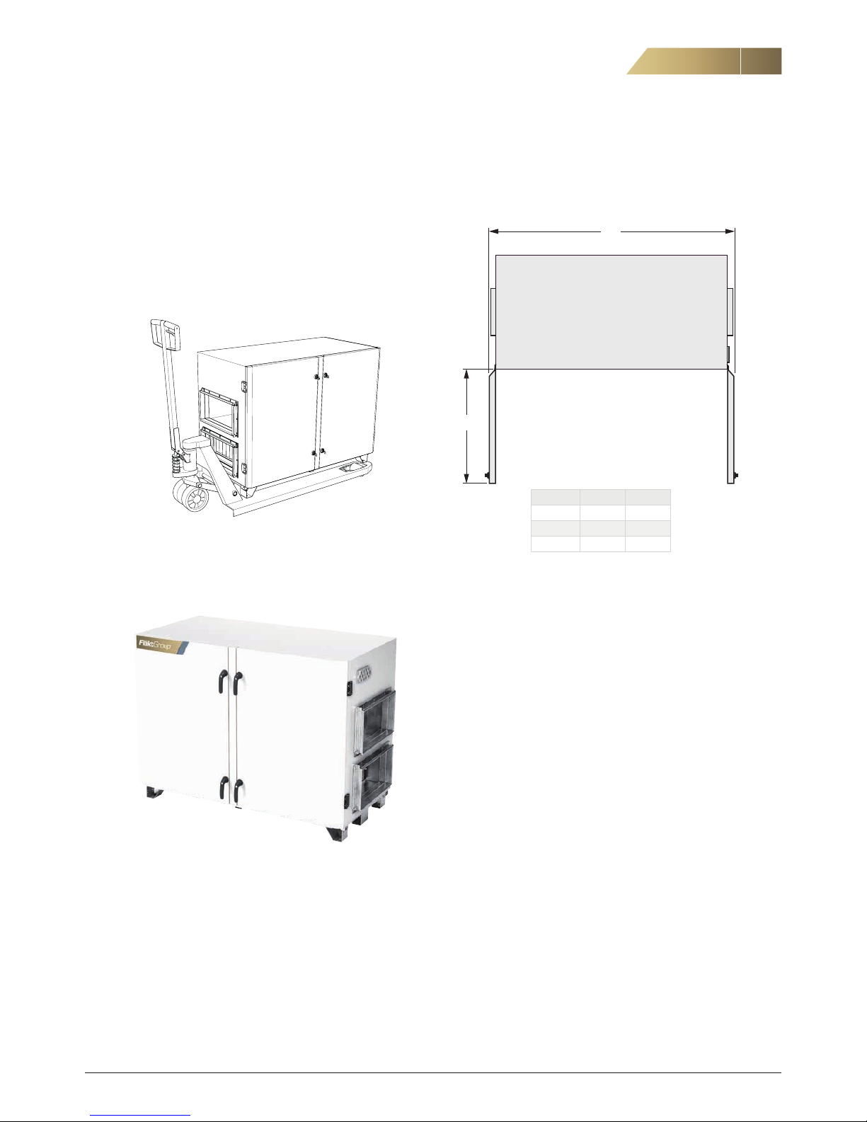
TRANSPORT
Use a fork lift truck, pallet truck or platform trolley for transport on
site. The unit can be lifted from the front or from the side.
To move size 06 through a 900 mm opening remove the door and
the center strut. See section 13.3.
3. TRANSPORT AND PLACEMENT
UNIT WEIGHT
Size 03 = 260 kg
Size 04 = 300 kg
Size 06 = 400 kg
SPACE REQUIREMENTS
Make sure that it is enough space around the unit for routine
service work, such as replacing filters and cleaning the fan and
casing.
Consideration has to be taken for future replacement of
com ponents.
PLACEMENT
The unit can be placed directly onto the surface if this is flat and
horizontal, otherwise use adjustable feet.
Available as accessory RDTZ-13.
Size B1 S
03 1683 730
04 1782 780
06 1945 861
B1 = width with open doors
S = minimum space for service*)
* in front of the control cabinet there has to be enough space
according to local electrical regulations.
B1
S
eCO Side - Installation and Maintenance Manual
6
FläktGroup DC_10176GB_20180924_R3 Specifications are subject to alteration without notice
NOTE! The weight of the duct system
with components must not lay weight on the unit.
4. CONNECTIONS
4.1 DUCT CONNECTIONS
Size 03 (Ø250 mm) and 04 (Ø315 mm) have circular duct connections. Size 06 has rectangular duct connections (600 x 300 mm).
4.2 POST HEATER, ELECTRICAL
The electrical post heater for size 06 is duct mounted, see separate instruction. The rectangular connection is PG on the unit and
the accessories. If the unit is selected with flange connection the
unit is delivered with an adapter for flange. This can be placed on
the unit or on the accessories. If the accessories are not placed
directly at the unit more adapters are available with the code
RDTZ-25-06-1.
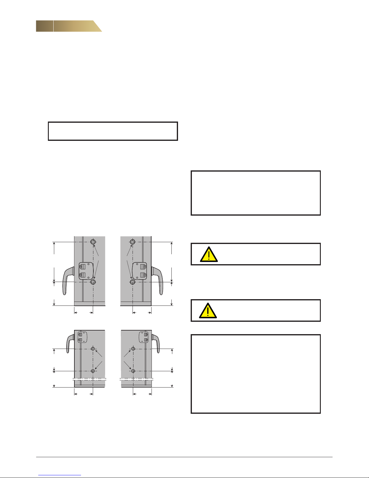
4.3 POST HEATER, HOT WATER
Connect the pipes for the heating coil inside the unit according to
pictures below. View from gables.
NOTE! To avoid freezing the temperatures for frost
protection must not be set too low. If the building
has to be left unheated for long periods during
winter, the water must be drained from both the
pipework and the heating coil.
WARNING! Wear protective gloves
when using a fin comb.
Warning - hot water!!
FläktGroup takes no responsibility neither for
the connection of air heaters to the heating
system, nor for damage or injury caused by
incorrect planning, installation or maintenance
of this system. Pipework, valves etc. are to be
designed due to pressure drop and function, not
the dimensions of the air heater connections. The
weight of the pipe work system with components
must not lay weight on the water coil.
PIPE CONNECTION
Size 03 = 3/8”
Size 04 = 12 mm
Size 06 = 12 mm
Maximum operating pressure 3.0 MPa
PREVENTING FREEZING
There is a risk of freezing in the hot water coil at low outdoor
temperatures. This can cause water damage. The risk can
appear:
1. if the temperature of the water is too high. The risk increases
in spring and autumn. Adjust the water temperature in relation
to the outdoor air temperature.
2. if the post heater is oversized. Decrease the temperature of
the water to increase the water flow.
FINS
Any deformed fins can be adjusted using fin comb EQAZ-14.
VENTING
The air must be properly vented from the system to ensure good
function. The venting is made through the pipe system.
Supply air bottom, right-hand version Supply air bottom, left-hand version
Supply air top, right-hand version Supply air top, left-hand version
Ø22.5
Ø22.5
03=108
04= 93
06=111
03=108
04= 93
06=111
03=238
04=272
06=304
03=135
04=132
06= 93
03=238
04=272
06=304
03=135
04=132
06= 93
03=108
04= 93
06=111
Ø22.5
Ø22.5
03=108
04= 93
06=111
03=238
04=272
06=304
03=491
04=559
06=534
03=238
04=272
06=304
03=491
04=559
06=534
eCO Side - Installation and Maintenance Manual
7
FläktGroup DC_10176GB_20180924_R3 Specifications are subject to alteration without notice
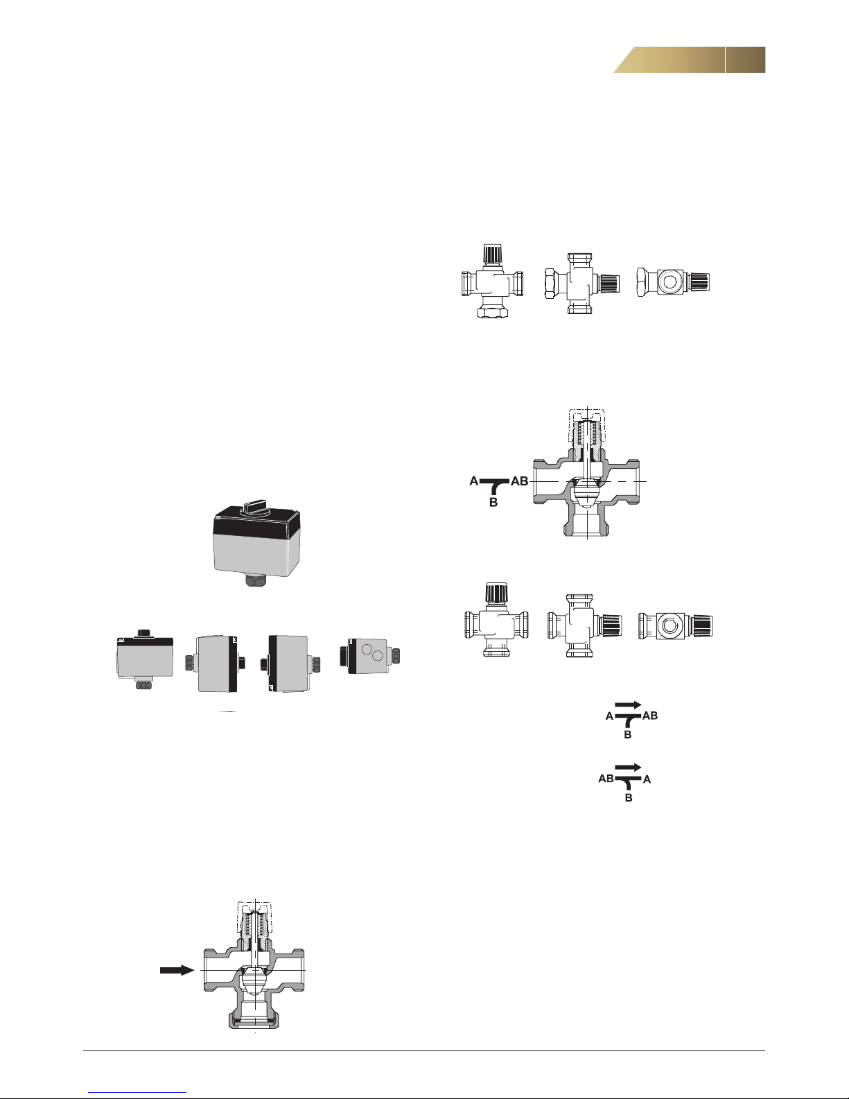
When installing a 3-way valve check as follows:
Mixture from A/B to AB
Splitting from AB to A/B
4.6 DAMPER
Duct mounted damper with a spring return on/off actuator. The
actuator has to be connected to the terminal block in the electri
cal cabinet. Size 03 and 04 have circular duct connections and
size 06 has rectangular. The damper is designed for duct insula
tion of up to 50 mm.
4.7 SILENCER, DUCT MOUNTED
Size 03 and 04 have circular duct connections and size 06 has
rectangular. Fire resistance rating EI30. The distance to the fan
has to be at least 300 mm.
4. CONNECTIONS
4.4 COOLING COIL, WATER
The cooling coils have circular duct connections with rubber
ring seals. For size 06 a converter from rectangular to circular
is available as an accessory (RDTZ-24). The cooler has to be
installed horizontally and the distance to nearest bend has to be
at least 600 mm. Venting and draining is carried out via the pipe
system. The pipe connection, Ø 22 mm, is located on the outlet
end, is smooth and is intended for a compression fitting. The
drainage tray is in stainless steel and has an R 1/2” connection.
Maximum operating pressure 1.0 MPa and maximum operating
temperature 150° C.
4.5 VALVE AND VALVE ACTUATOR
ACTUATORS FOR HEATING SV1 AND COOLING SV2
Connected to terminal in electrical cabinet. Stroke length 5.5 mm.
Intended for assembly on 2-way and 3-way valves of the type
VVG44 or VXG44.
ACCEPTED INSTALLATION METHODS
VALVE FOR HEATING AND COOLING
The valve and valve actuator can be easily installed without
special tools. A particle filter should be fitted before the valve to
extend its service life.
2-WAY VALVE VVG
The flow is increased by turning the spindle inwards, the flow is
reduced by moving the spindle outwards. Note that the 2-way
valve cannot be used as a 3-way valve.
The flow direction is indicated by an arrow.
ACCEPTED INSTALLATION METHODS
3 - WAY VA LVE V X G
The bypass is closed by turning the spindle inwards, the bypass
is opened by turning the spindle outwards.
ACCEPTED INSTALLATION METHODS
eCO Side - Installation and Maintenance Manual
8
FläktGroup DC_10176GB_20180924_R3 Specifications are subject to alteration without notice
5. ELECTRICAL CONNECTIONS
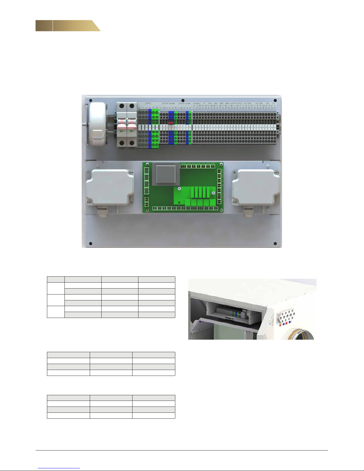
5.3 MAIN SUPPLY
NY BILD!
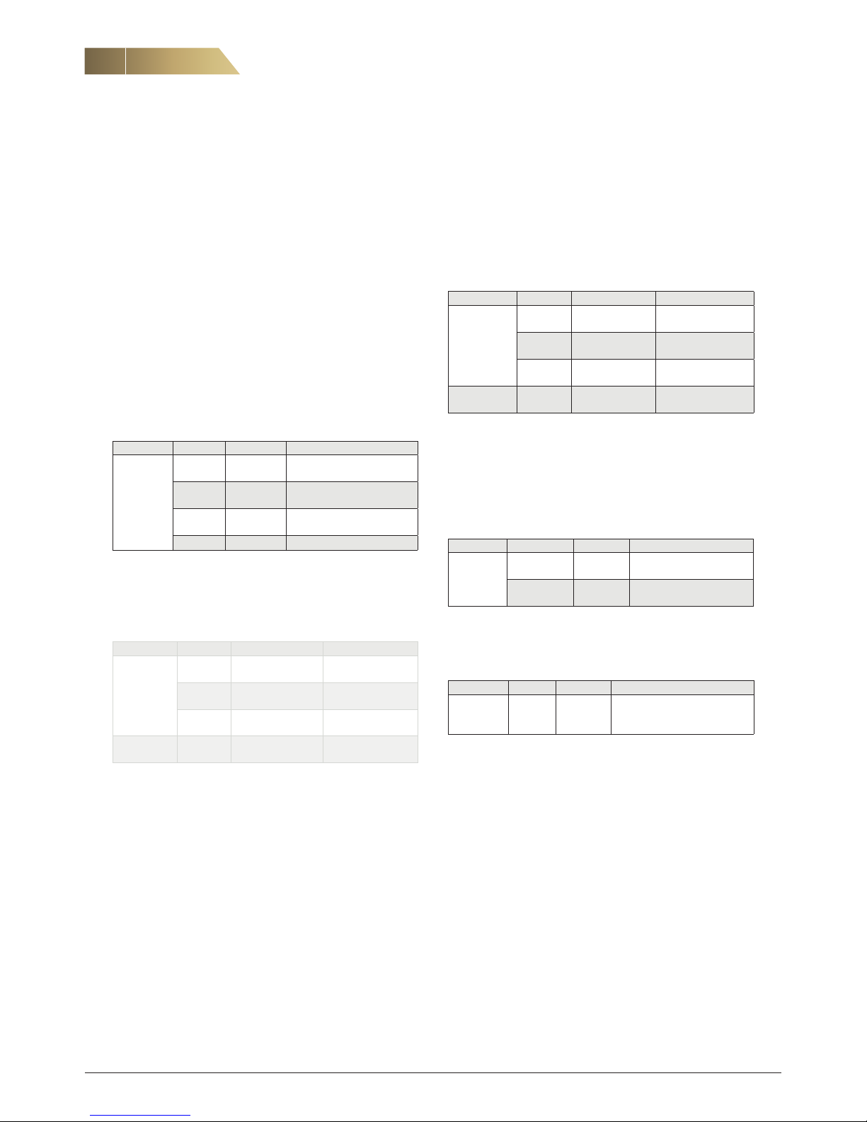
5.1 FUSE PROTECTION
Size Unit with Hot water coil Electrical coil
03
Supply 1 x 230 V 3 x 400 V
Fuse 10 A 10 A
04
Supply 1 x 230 V 3 x 400 V
Fuse 10 A 16 A
06
Supply 1 x 230 V 1 x 230 V
1)
Fuse 10 A 10 A
1)
Duct mounted heater size 06 has sparate supply.
5.2 ELECTRICAL DATA
MOTORS
Size Power, kW Current, A
03 0,385 x 2 2,5 x 2
04 0,50 x 2 2,2 x 2
06 0,75 x 2 3,3 x 2
ELECTRICAL POST HEATER
Power, kW Current, A Voltage, V
4 10 2 x 400
6 15 2 x 400
9
1)
13 3 x 400
1)
Duct mounted heater size 06 has sparate supply.
Units with built-in electrical heater, main supply 3 x 400V.
Units with hot water coil can be supplied with 1 x 230V.
Units with duct mounted electrical heater can be supplied with 1
x 230V.
Units are not available for 3 x 230V..
The main supply cable must be fitted with an external safety
switch located close to the unit. Connect main supply to terminals
U, V, W, N and PE in the control box.
eCO Side - Installation and Maintenance Manual
9
FläktGroup DC_10176GB_20180924_R3 Specifications are subject to alteration without notice
5. ELECTRICAL CONNECTIONS
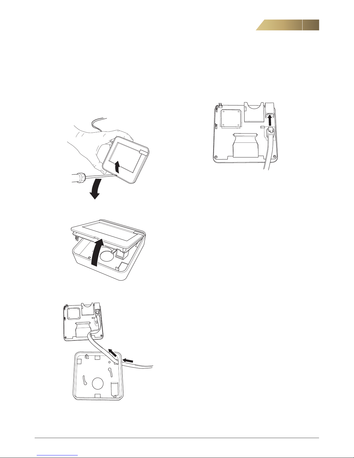
1. Open the control panel using a screwdriver.
5.4 CONNECTION OF CONTROL PANEL
The control panel is connected when delivered from factory and
provided with a magnet for easy handling. For wall mounting see
below.
2. Lift the display out of the enclosure.
3. Push the connection cable through a suitable hole and if
needed make an outlet for the cable in the side of the cover.
4. Mount the enclosure directly on the wall.
5. Connect the cable to the back of the display as shown above.
Note. Please do not touch the electronics.
6. Push back the display in the enclosure.
NOTE! The control panel is only for indoor use.
eCO Side - Installation and Maintenance Manual
10
FläktGroup DC_10176GB_20180924_R3 Specifications are subject to alteration without notice
6.1 ELECTRICAL POST HEATER (SIZE 06, 9 KW)
Duct mounted. Separate supply 3 x 400V, 16 A.
Connect alarm, start and control signal to the control box in the
unit. eCO Side is preconfigured for electrical post heater.
(Electrical heater for size 03 and 04 is built-in in the unit, no
further connections are needed).
Component Terminal Connection Remark
Electrical
heater
9 kW
CP1/SK1
Heater
1 – 2
C- NO
Start signal
ALM CP1
43 – 44
NO - C
Alarm, overheating (NC)
SV1 CTRL
35 – 36
Y - M
Control signal 0-10 V
Supply 3 x 400 V
Not from the unit
6.2 POST HEATER, HOT WATER
Circulation pump (CP1) and valve actuator (SV1) connects
according to table below.
Component Terminal Connection Remark
Circulation
pump CP1
CP1/SK1
Heater
1 – N – PE
Pump supply
(230 V max 2A
1)
CP1/SK1
Heater
2 - 3
NO – L1
Loop only with
circulation pump
ALM CP1
43 – 44
NO - C
Voltfree alarm input
(NO, configurable)
Valve
actuator SV1
SV1 CTRL
35 – 36 – 37 - 38
Y – M – G – G0
1)
The current consumption for CP1 and CP2 is limited to 2 A.
6. CONNECTION OF EXTERNAL COMPONENTS
6.3 COOLING COIL, WATER
Circulation pump (CP2) and valve actuator (SV2) connects
according to table below.
Component Terminal Connection Remark
Circulation
pump CP2
CP2/DX
Cooler
4 – N – PE
Pump supply
(230 V max 2A
1)
CP2/DX
Cooler
5 - 6
NO – L1
Loop only with
circulation pump
ALM CP2/DX45 – 46
NO - C
Voltfree alarm input
(NO, configurable)
Valve
actuator SV2
SV2 CTRL
39 – 40 – 41 - 42
Y – M – G – G0
1)
The current consumption for CP1 and CP2 is limited to 2 A.
6.4 COOLING COIL, DX
The unit can manage cooling DX, 1-step. Note that the coil is not
included in the delivery of the unit. For configuration see control
functions.
Component Terminal Connection Remark
DX-cooling,
1-step
CP2/DX
Cooler
4 – 5
C – NO
Start: 10 %
Stop: 0 %
ALM CP2/DX
45 – 46
NO - C
Voltfree alarm input (NO,
configurable)
6.5 DAMPER
On/off actuator with spring return, 15 Nm, 24 VAC.
Component Terminal Connection Remark
Damper ST1
29 – 30
G – G0
Exhaust air damper if used
is connected in parallel
(Maximum 2 dampers)
Use the cable flange on the top of the unit to connect all external
accessories.
For information about how to connect available accessories see
below.
eCO Side - Installation and Maintenance Manual
11
FläktGroup DC_10176GB_20180924_R3 Specifications are subject to alteration without notice
6. CONNECTION OF EXTERNAL COMPONENTS
6.6 TEMPERATURE SENSORS
The unit is provided with:
Supply air sensor GT1, located at supply air spigot.
Outdoor air sensor GT3, located at outdoor air spigot.
Frost protection sensor GT5 (when hot water coil is used), located
on the return pipe of the coil.
When using cooling coil or duct mounted post heater a supply
temperature sensor (GT1) is supplied for duct mounting. Then
there is no supply air sensor mounted in the unit.
Room sensor GT2 (accessory) is supplied when the unit is con
figured for room temperature control. Then there is no exhaust air
sensor mounted in the unit.
The room sensor is intended for wall mounting and needs to have
good air circulation and not direct sun light. Cable is not included.
Component Terminal Connection Remark
Supply air
sensor
GT1
25 – 26
B – M
Standard sensor is replaced
with a duct mounted sensor
when using cooling coil or duct
mounted heater
Room
sensor
GT2
27 – 28
B – M
Replaces exhaust air sensor
GT12 when room control is
selected
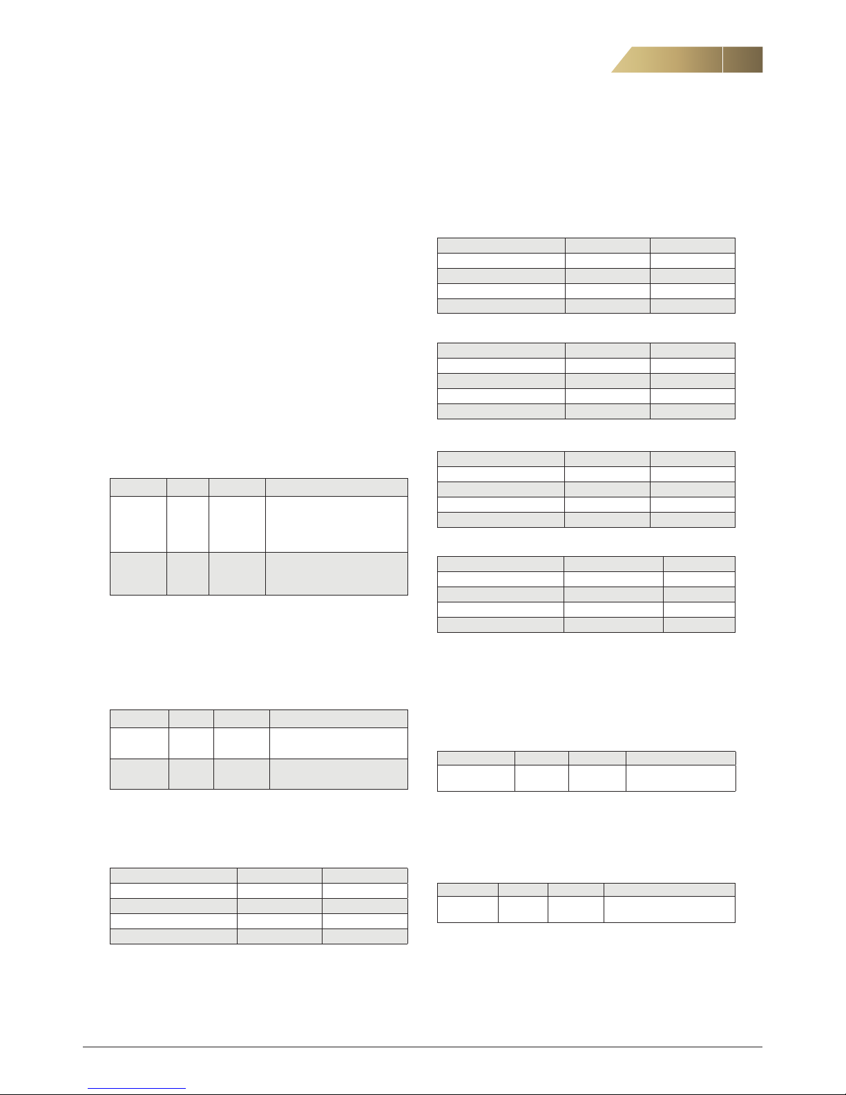
6.7 EXTENDED / FORCED VENTILATION
For external electronic timer, push button, PIR or other volt free
contact. Electronic timer and/or PIR if ordered is supplied
separately. When using a push button the time has to be set in
the control panel.
Component Terminal Connection Remark
Timer 1 TMR1
31 - 32
NO - C
Can also be used for PIR
Timer 2 TMR2
33 – 34
NO - C
Can also be used for PIR
Function of aux. inputs Timer 1 (T1) and Timer 2 (T2) can be
selected according to the following tables.
TIMER FUNCTION 1 (DEFAULT)
Timer 1 Timer 2
Manual/Automatic Mode 0 0
Trickle 1 0
Normal 0 1
Boost 1 1
TIMER FUNCTION 2
Timer 1 Timer 2
Manual/Automatic Mode 0 0
Trickle 1 0
Boost 0 1
Stop 1 1
TIMER FUNCTION 3
Timer 1 Timer 2
Manual/Automatic Mode 0 0
Normal 1 0
Boost 0 1
Stop 1 1
TIMER FUNCTION 4
Timer 1 Timer 2
Stop 0 0
Manual/Automatic Mode 1 0
Stop 0 1
Boost 1 1
TIMER FUNCTION 5
Timer 1 Timer 2
Stop 0 0
Manual/Automatic Mode 1 0
Stop 0 1
Normal 1 1
6.8 FIRE PROTECTION FUNCTION
External fire alarm to stop the unit can be connected to terminals
in the control box.
Smoke detectors and fire dampers cannot be connected directly
to the air handling unit, a separate fire system is needed.
Component Terminal Connection Remark
Fire protection
function
FIRE
23 – 24
NC – C
6.9 SUMMARY ALARM
The alarm output can be configured to indicate A-alarms or both
A- and B-alarms.
Component Terminal Connection Remark
Summary
alarm
ALARM
21 – 22
NO – C
Voltfree contact
Maximum load 24 V, 200 mA
eCO Side - Installation and Maintenance Manual
12
FläktGroup DC_10176GB_20180924_R3 Specifications are subject to alteration without notice
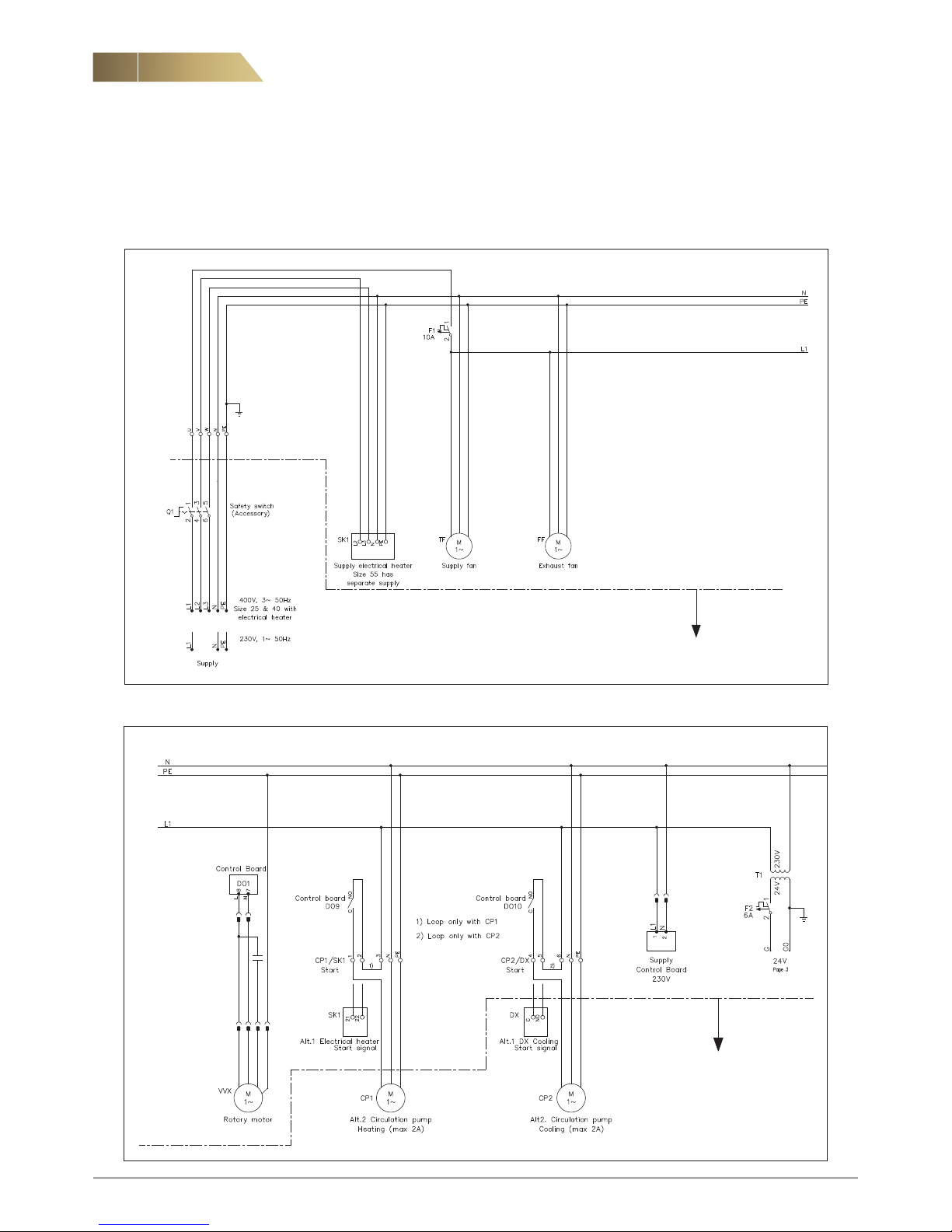
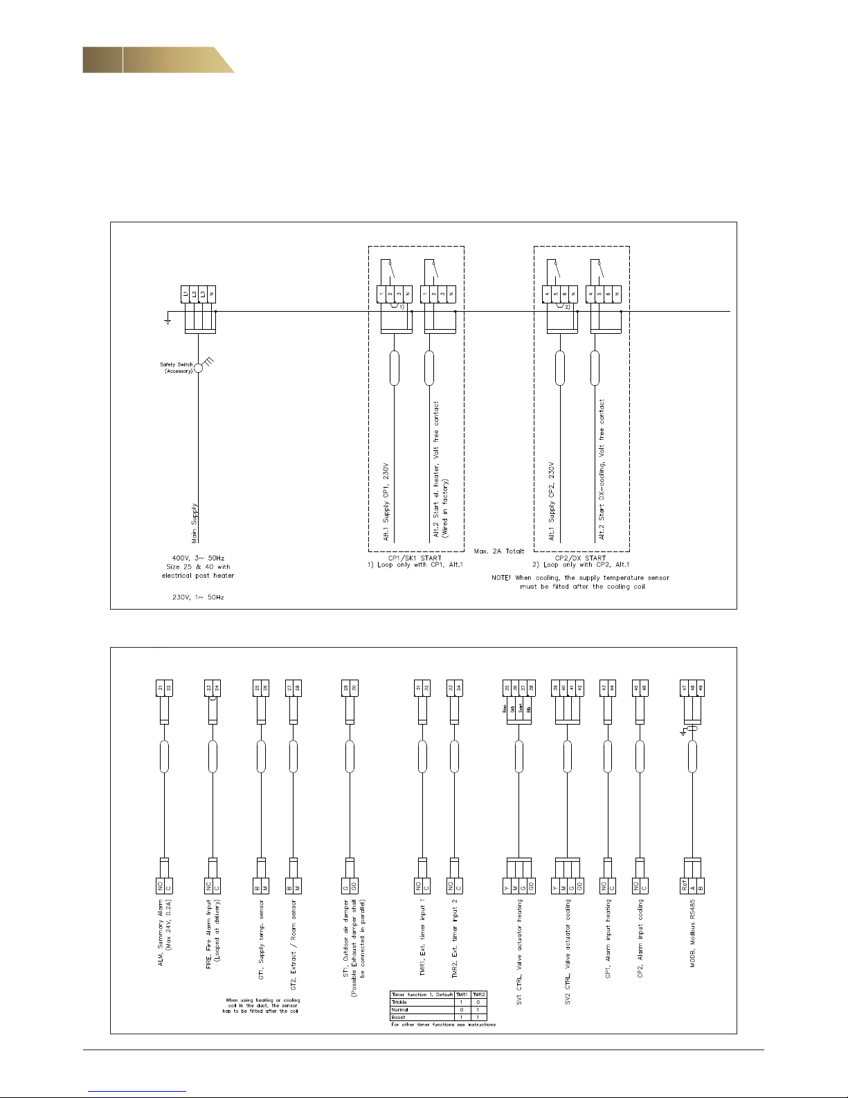
7. WIRING DIAGRAMS
Outside the AHU
Not in FläktGroup’s delivery
Outside the AHU
Not in FläktGroup’s delivery
eCO Side - Installation and Maintenance Manual
13
FläktGroup DC_10176GB_20180924_R3 Specifications are subject to alteration without notice
7. WIRING DIAGRAMS
Control panel
ISYteq Touch 3.5”
Control board
eCO Side - Installation and Maintenance Manual
14
FläktGroup DC_10176GB_20180924_R3 Specifications are subject to alteration without notice
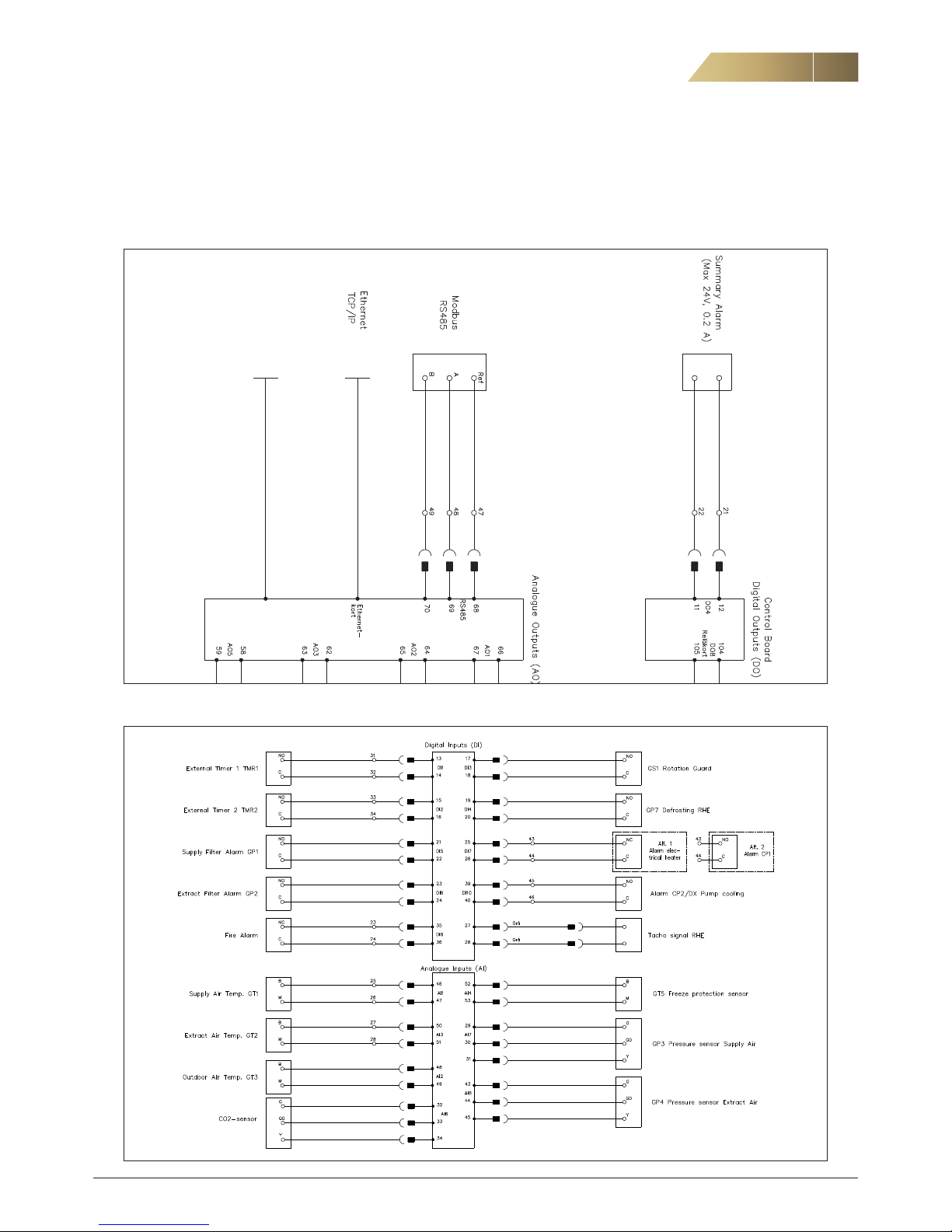
7. WIRING DIAGRAMS
EXTERNAL CONNECTIONS DIAGRAM
230/400 V
EXTERNAL CONNECTIONS DIAGRAM 24 V
eCO Side - Installation and Maintenance Manual
15
FläktGroup DC_10176GB_20180924_R3 Specifications are subject to alteration without notice
STARTING THE UNIT
When the electrical connections are made and all the accessories are mounted the unit is ready to start up.
1. Turn the safety switch to 1 (ON).
2. Start the unit.
DAMPERS
Check that all dampers opens and closes correctly.
VALVE ACTUATORS
Check that valve actuators for heating and cooling works correctly.
DIRECTION OF ROTATION
Check that the direction of rotation for the heat exchanger corresponds to the alternatives below.
LEFT-HAND VERSION:
The rotor should rotate upwards when looking from the front.
RIGHT-HAND VERSION:
The rotor should rotate downwards when looking from the front.
AIR FLOW MEASUREMENT
The eCO Side has measuring nipples for air flow measurement.
Using a measuring pressure Dpm (Pa) and a constant (k) the air
flow q (R/W) can be calculated using the following equation:
NOTE! When the unit is supplied with
Constant Air Volume Control there will be
no measuring nipples on top of the unit.
TEMPERATURE CORRECTION
The air flow formula above applies to air with a temperature of
+20 °C. At other air temperatures the air flow must be corrected
using the formula:
The value of the constant (k) is shown in the table below.
q =
1000
k
Dp
m
x
Size
03 04 06
k-value extract air fan
58,4 51,5 49,2
k-value supply air fan
62,5 52,1
51,4
The measuring pressure, Dpm, is the difference between the
pressure in the empty section at the fan inlet and the pressure
inside the inlet cone. A manometer (RDTZ-56) can be connected
to view the measuring pressure. This is used as a reference for
monitoring the unit.
If the unit is supplied with Constant Air Volume control the air
flow can be read in the control panel.
q = q
20
(273 + t)
293
, m
3
/s
8. TESTING OF FUNCTIONS
q = actual air flow
q
20
= calculated air flow in formula abowe
t = current temperature in ° C
FILTER, FINAL PRESSURE DROP
It is time to replace the filters when the final pressure drop is
reached, see table below.
SIZE 03
Air flow m3/s 0,15 0,25 0,35
Supply air/Extract air 119 148 177
SIZE 04
Air flow m3/s 0,15 0,25 0,35
Supply air/Extract air 125 142 159
SIZE 06
Air flow m3/s 0,15 0,25 0,35
Supply air/Extract air 121 139 157
FILTER MONITOR
When using filter monitors use the values in the table above. If
the unit is supplied with Constant Pressure control increase the
final pressure drop with 50 Pa.
 Loading...