

FläktGroup CPD Series, CPDD, CPDL, CPDF Operation, Maintenance, Installation, Commissioning, Spare Parts
COOKER HOOD
CPD
OPERATION, MAINTENANCE, INSTALLATION, COMMISSIONING, SPARE PARTS

2
2
Cooker hood CPDD, CPDL - Installation and Maintenance Manual
CONTENTS
OPERATION AND MAINTENANCE (FOR USER)
Cleaning of cooker hood ......................................................................... 3
Cleaning of grease filters ......................................................................... 3
Replacement of low energy lamp ........................................................ 3
General information .................................................................................... 3
Operation .........................................................................................................4
CPDL - Setting of supply air temperature ......................................... 5
INSTALLATION (FOR INSTALLER AND SERVICE PERSONNEL)
CPDD for heat recovery unit ACF ..........................................................7
CPDD for BAF extract air fan ................................................................ 9
CPCZ-07 Installation of nipples (ACF before 1988) ................... 10
CPDL for heat recovery units RDKB and RDKE ............................ 11
ADJUSTMENT, COMMISSIONING (FOR INSTALLER AND SERVICE PERSONNEL)
Basic ventilation ........................................................................................17
Forced ventilation .....................................................................................18
MISCELLANEOUS
Spare parts CPDD, CPDF, CPDL ..................................................................19
Declaration of conformity ...............................................................................20
Disposal of products and packaging materials .....................................21
WARNING! THE APPLIANCE MAY BE USED BY CHILDREN OVER THE AGE OF 8, PERSONS (INCLUDING
CHILDREN) WITH PHYSICAL, SENSORY OR MENTAL DISABILITIES OR LACK OF KNOWLEDGE OR
EXPERIENCE, PROVIDED THEY HAVE RECEIVED INSTRUCTION OR INFORMATION ON SAFE USE OF THE
APPLIANCE AND UNDERSTAND THE POTENTIAL RISKS. CHILDREN MAY NOT PLAY WITH THE APPLIANCE.
CHILDREN MAY NOT CLEAN OR PERFORM MAINTENANCE ON THE APPLIANCE WITHOUT SUPERVISION.
FläktGroup DC_8759GB_20190207_R1 We reserve the right to make changes without prior notice
Cooker hood CPDD, CPDL - Installation and Maintenance Manual
1
2
33
OPERATION AND MAINTENANCE
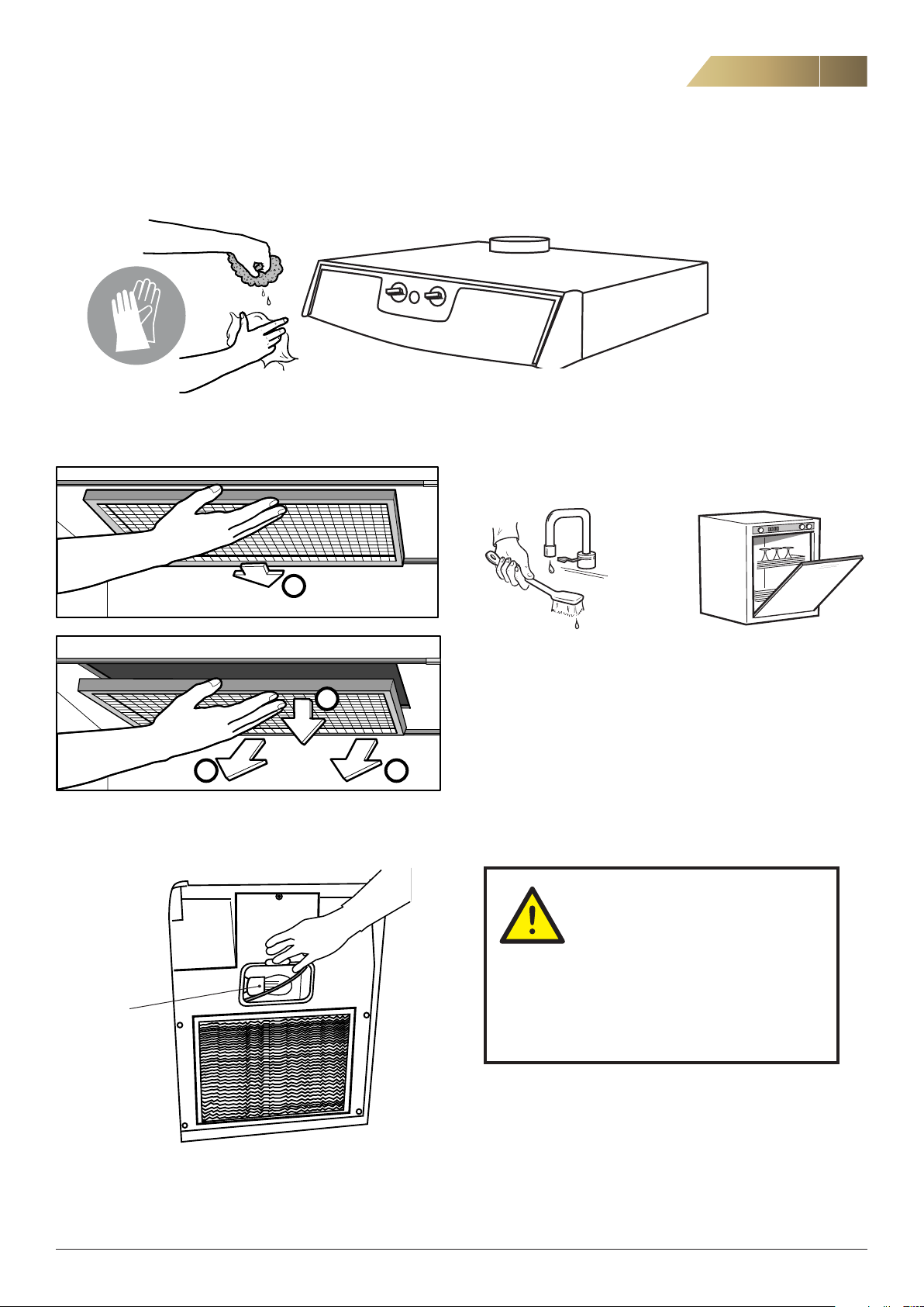
CLEANING THE COOKER HOOD
Do not use abrasive sponge or cloth.
3
CLEANING OF GREASE FILTERS
REPLACEMENT OF LOW ENERGY LAMP
NOTE! Do not use the cooker hood
without the grease filters fitted.
alt.
Check the grease filters every week.
Clean if needed, either by hand or in a dishwasher.
GENERAL
There is a fire risk if grease filters are not
cleaned according to the instructions.
The cooker hood may become hot during cook
ing.
Do not flambé under the cooker hood.
11 W/E14
FläktGroup DC_8759GB_20190207_R1 We reserve the right to make changes without prior notice
If the supply cord is damaged, it must be replaced by the
manufacturer, the distributor or a similarly qualified professional in order to avoid hazard.
-
4
4
OPERATION AND MAINTENANCE
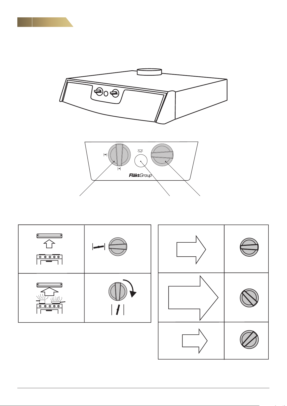
OPERATING OF CPDD, CPDL
Cooker hood CPDD, CPDL - Installation and Maintenance Manual
2
1
MIN
Booster knob Lighting Fan speed adjustment knob
2
NORMAL
1
MIN
2
MAX
1
MIN
2
MIN
1
MIN
FläktGroup DC_8759GB_20190207_R1 We reserve the right to make changes without prior notice
Cooker hood CPDD, CPDL - Installation and Maintenance Manual
OPERATION AND MAINTENANCE
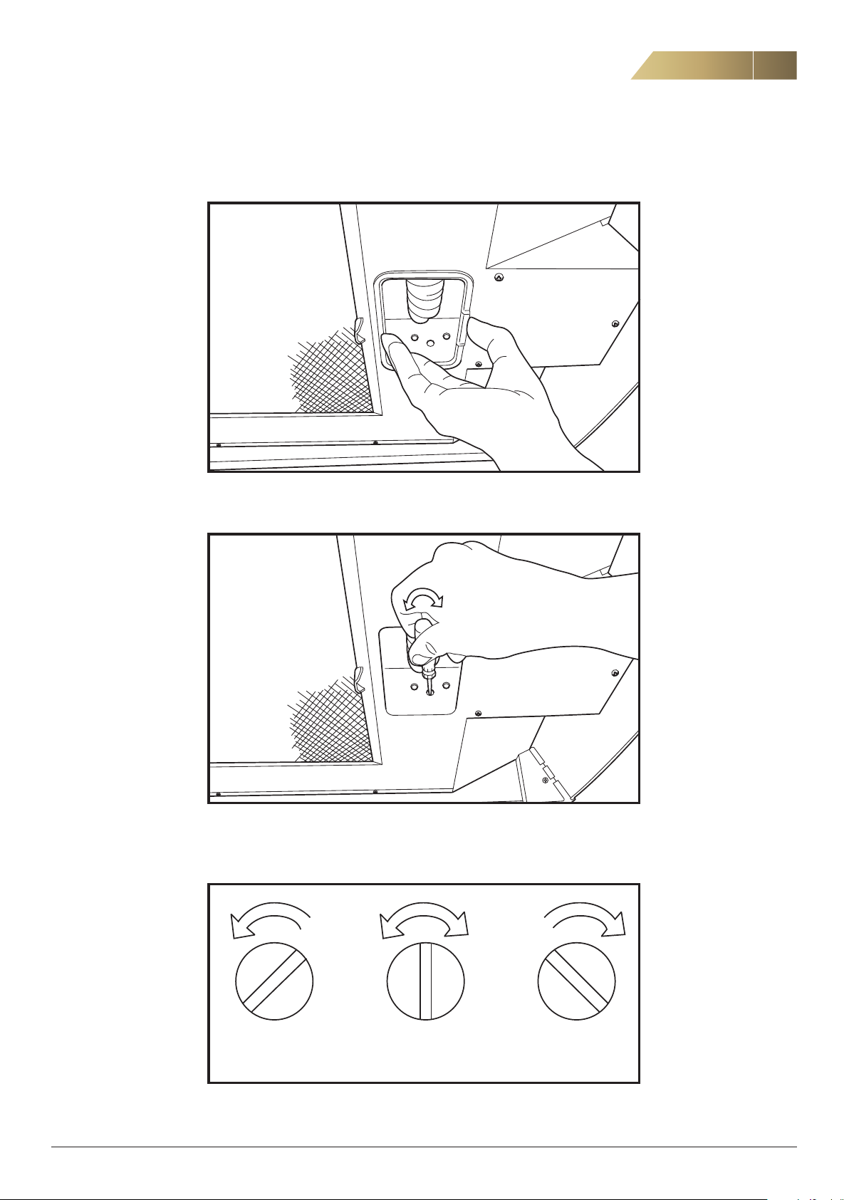
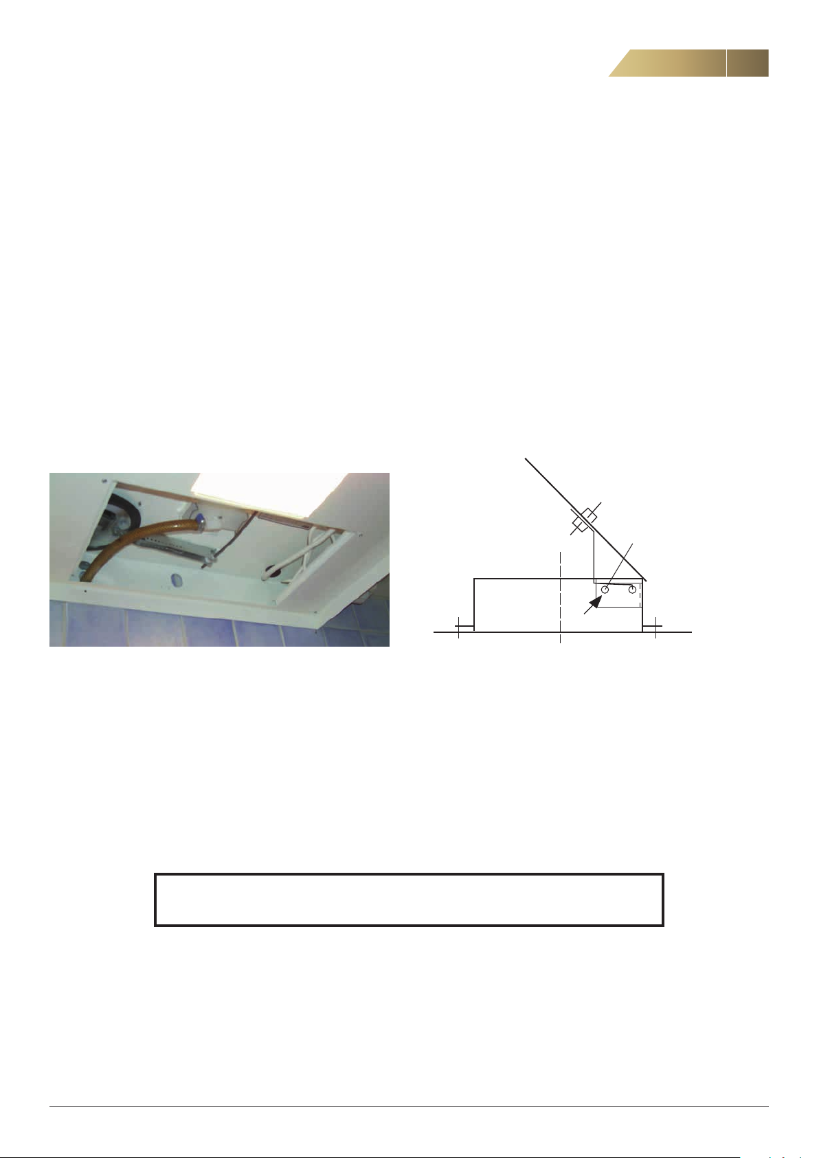
CPDL - SETTING OF SUPPLY AIR TEMPERATURE (POSTHEATER)
5
1. Remove the lamp glass.
2. Use a screwdriver to set the supply air temperature downstream of the
ventilation unit. The factory setting is 10 °C.
Factory setting
Min - Off 10° C 20° C
3. The supply air temperature downstream of the unit can be adjusted steplessly
between the lowest setting and 20 °C.
FläktGroup DC_8759GB_20190207_R1 We reserve the right to make changes without prior notice
6
6
OPERATION AND MAINTENANCE
CPDL - SETTING OF SUPPLY AIR TEMPERATURE (POSTHEATER)
Cooker hood CPDD, CPDL - Installation and Maintenance Manual
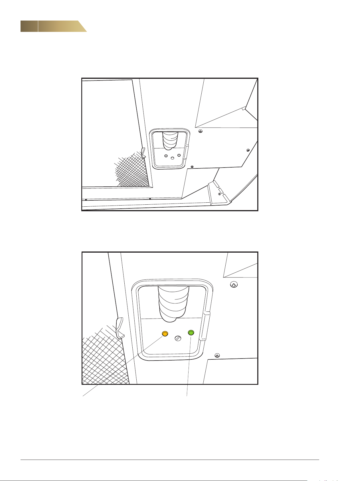
4. The indicator lights for the electric post-heater and defrosting functions are located in the cooker hood as shown in the figure above.
If the yellow light is illuminated, the
electric post-heater is in operation.
FläktGroup DC_8759GB_20190207_R1 We reserve the right to make changes without prior notice
If the green light is illuminated, de
frosting is in progress.
-
Cooker hood CPDD, CPDL - Installation and Maintenance Manual
INSTALLATION (FOR INSTALLER AND SERVICE PERSONNEL)
CPDD FOR HEAT RECOVERY UNIT ACF
All cooker hoods must be connected directly or indirectly via the heat recovery unit/extract air fan to earth.
7
PROCEDURE
1. Disconnect the unit from the power supply by pulling out the
plug.
If the hood is permanently attached, the work must be performed by a qualified installation engineer.
2. Note the switch position for Normal operating speed.
The switch is on the top of the cooker hood. There are six settings on the switch. The switch is accessed by opening the
door to the ventilation unit.
3. Disconnect the drainage hose from the cooker hood.
4. Remove the BHG hood. The hood is attached with four screws
which are accessed by opening the door to the unit.
5. Connection to drainage hose.
Alt. 2
a) Make a vertical slit in the wall measuring 70 mm. Pull the drain-
age hose upwards until it protrudes roughly 40 mm below the
lower edge of the unit. Adjust the nipple on the drainage cup so
that it points sideways towards the hose. Remove the grease
filter and the cover plate on the new hood and, if necessary,
reposition the cable on the transformer until it is tensioned in
the same way as on the old transformer. By default, the cable is
connected to pin 5, which is 150 V. It is easiest to set the volt
age before installing the hood.
6. Before installation, prepare the fire damper by fixing it with the
included melting rivet (125 °C). Flatten the end of the rivet using
pliers.
-
Melting rivet
Alt. 1
a) Make a slit in the wall large enough for the drainage hose to fit
through. The slit should reach from approximately 10 mm below
the centre on the bottom of the unit down to the drainage hose.
B) Position the drainage hose so that it protrudes out of the wall
25 mm below the lower edge of the unit. If a new hose needs to
be installed, it must be armoured to prevent creasing. Position
the hose so that if forms a water trap. Use the old hose’s posi
tion for reference.
NOTE! INSTALLATION, COMMISSIONING AND ADJUSTMENT AS DESCRIBED IN THESE
INSTRUCTIONS MUST BE CARRIED OUT BY QUALIFIED AND AUTHORISED PERSONNEL.
7. Install the cooker hood under the ventilation unit, using the
screws and mounting plate from the old cooker hood. Make
sure the hood creates a tight seal against the unit. Replace the
sealing strip under the unit if necessary.
-
FläktGroup DC_8759GB_20190207_R1 We reserve the right to make changes without prior notice
8
D
Bakkant kåpa
8
Cooker hood CPDD, CPDL - Installation and Maintenance Manual
INSTALLATION (FOR INSTALLER AND SERVICE PERSONNEL)
CPDD FOR HEAT RECOVERY UNIT ACF, CONT’D.
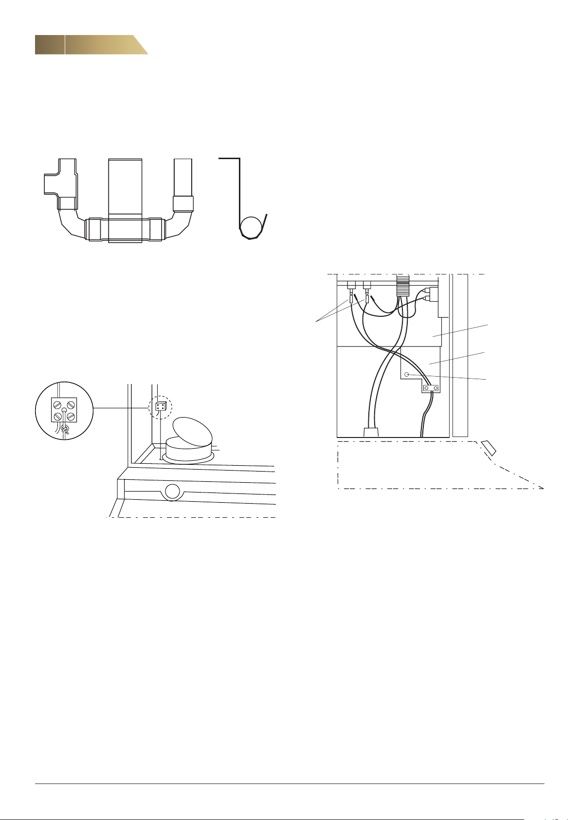
8. Assemble the water trap as shown in the figure.
9. Connect the drainage hose to the water trap. Make sure that
the damper is not obstructed by the drainage hose when it is in
the open position, and that a water trap cannot form inside the
hood.
10. Connect the damper valve in the cooker hood with the throttle
damper in the ventilation unit. To do this, thread the nylon line
through the terminal block and tighten the screws while the
valve in the cooker hood is closed and the damper in the venti
lation unit is open.
NOTE! The CPDD cooker hood does not have a power output indicator
light. If a CPDD hood is to be used to replace a BHG.614100, the fol
lowing steps must be carried out by a qualified electrician:
1. Remove the cover plate E in the ventilation unit and disconnect
the cables from the element connections D.
2. Remove the cables for the indicator light from the disconnected
cables (double AMP).
3. Reconnect the AMP cables to the element connections.
4. Remove the strain relief connector A in screw B.
5. Connect cover plate E and fix it securely into place.
-
E
-
A
B
11.
Connect the 12-pole connector to the corresponding connection
point in the unit.
12. Reinstall the filter. Plug the plug for the cooker hood into the
earthed wall socket.
13. Check whether the air flow settings (Settings 1 and 2) feel right.
The adjustment damper in the hood is delivered with a factory
setting that is suitable for most installations.
14. Cover any untreated surfaces underneath the cooker hood with,
for instance, a teak strip.
FläktGroup DC_8759GB_20190207_R1 We reserve the right to make changes without prior notice
 Loading...