

Page 1
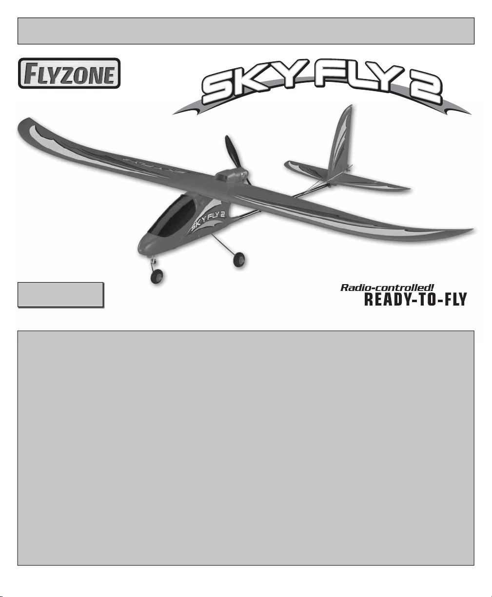
COMPLETE RTF AIRPLANE
™
REQUIRES:
8 “AA” Alkaline Batteries
Please retain this information for future reference.
™
ASSEMBLE ONLY WITH ADULT SUPERVISION
Please read through this instruction booklet to THOROUGHLY familiarize yourself with the assembly and fl ight characteristics of this
airplane before beginning to assemble the kit.
Please inspect all parts carefully before starting assembly! If any parts are missing, broken or defective, or if you have any questions
about the assembly or fl ying of this airplane, please call us at (217) 398-8970 and we’ll be glad to help.
WARRANTY
Hobbico® guarantees this kit to be free from defects in both material and workmanship at the date of purchase. This warranty does
not cover any component parts damaged by use or modifi cation. In no case shall Hobbico’s liability exceed the original cost of
the purchased kit. Further, Hobbico reserves the right to change or modify this warranty without notice.
In that Hobbico has no control over the fi nal assembly, no liability shall be assumed nor accepted for any damage resulting from the use
by the user of the fi nal user-assembled product. By the act of using the user-assembled product, the user accepts all resulting liability.
If the buyers are not prepared to accept the liability associated with the use of this product, they are advised to return this
kit immediately in new and unused condition to the place of purchase.
To make a warranty claim send the defective part or item to Hobby Services at the address below:
Hobby Services
3002 N. Apollo Dr., Suite 1
Champaign IL 61822 USA
Include a letter stating your name, return shipping address, as much contact information as possible (daytime telephone number,
fax number, e-mail address), a detailed description of the problem and a photocopy of the purchase receipt. Upon receipt of the
package the problem will be evaluated as quickly as possible.
Entire Contents © Copyright 2008 Printed in China HCAA41xxMnl01
Page 2
PROTECT YOUR MODEL, YOURSELF
AND OTHERS; FOLLOW THESE
IMPORTANT SAFETY PRECAUTIONS
Your SkyFly 2 should not be considered a toy, but
rather a sophisticated, working model that functions
very much like a full-size airplane. Because of its
performance capabilities, the SkyFly 2, if not assembled
and operated correctly, could possibly cause injury to
you or spectators and damage to property.
instructions to end up with a well-built model
that is durable and easy to fl y. The R/C model
hobby becomes more and more enjoyable as your
experience grows. Your chances for success and
graduation to higher levels are very good if you
take your time and follow the assembly and fl ying
instructions carefully and completely. We hope you
enjoy fl ying your SkyFly 2 airplane.
We highly recommend that you get experienced,
knowledgeable help with assembly and during
your fi rst fl ights. This will make your modeling
experience more enjoyable. You’ll learn faster and
avoid risking your model before you are truly ready
to solo. Your local hobby shop has information about
fl ying clubs in your area whose membership includes
qualifi ed instructors. You can contact the Academy
of Model Aeronautics (AMA), which has more than
2,500 chartered clubs across the country. Instructor
training programs and insured newcomer training are
available through any one of these clubs.
Contact the AMA at the address or toll-free phone
number below.
Academy of Model Aeronautics
5151 East Memorial Drive
Muncie, IN 47302
(800) 435-9262 Fax: (765) 741-0057
or via the Internet at: www.modelaircraft.org
PRECAUTIONS
1. Assemble the plane according to instructions.
DO NOT alter or modify the model. If you make any
modifi cations, you void your warranty.
2. Test the operation of the model before each fl ight
to insure that all equipment is operating properly and
that the model remains structurally sound.
GLOSSARY
Electronic Speed Control/Receiver (ESC/RX):
This unit controls the speed of the motor and
control surfaces.
Elevator: Control altitude.
Rudder: Controls direction.
Nickel-Metal Hydride (NiMH) Battery:
Rechargeable batteries which are used to power the
airplane. NiMH batteries are lighter and smaller than
most other types of rechargeable batteries.
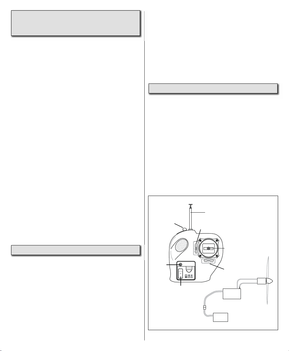
Transmitter (TX): This is the hand-held unit that
sends the signal to the control unit (or RX). Moving the
controls will control speed, altitude and direction.
ANTENNA
THROTTLE
SLIDE
POWER
LED
ON/OFF SWITCH
3-CHANNEL RADIO
CONTROL SYSTEM
ON
REV
NOR
TACT IC
TTX300
CH1
CH3
CH2
ELEVATOR TRIM
CONROL STICK
RUDDER TRIM
ESC/
Receiver
Motor
3. Fly only on calm days (with wind speeds less than
5mph) and in large, open areas free of trees, people,
buildings, or any other obstacles.
Remember: Take your time and follow the
Battery
2
Page 3

AIRFRAME PARTS AND HARDWARE
Before starting to build, take an inventory of this kit to make sure it is complete and inspect the parts to make
sure they are of acceptable quality. If you need assistance with assembly, contact Product Support. When
reporting defective or missing parts, please use the part names exactly as they are written in the parts list.
1
11
10
9
1. Fuselage
2. Wing
3. Horizontal Stabilizer
4. Vertical Fin
5. Tactic 3-Channel Transmitter
6. Rubber Bands
6
7
3
4
8
2
5
7. Main Landing Gear Assembly
8. Nose Gear Assembly
9. NiMH 8.4V 900mAh Battery
10. 12V DC Peak Charger
11. 120V AC Wall Adapter
FCC REQUIREMENT
This device complies with Part 15 of the FCC Rules. Operation is subject to the following
two conditions: (1) This device may not cause harmful interference, and (2) This device must
accept any interference received, including interference that may cause undesired operation.
CAUTION: Changes or modifi cations to this product not expressly approved by the party responsible for
compliance may void the user’s authority to operate the equipment.
3
Page 4
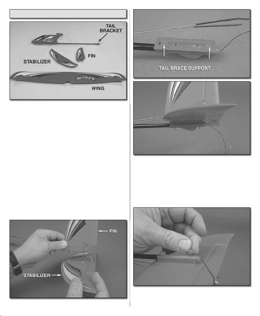
ASSEMBLE THE TAIL
Remove the fuselage from the packaging. Lay the
parts out on a table. You will notice the receiver
antenna wire extends from the back of the fuselage.
DO NOT CUT OFF THE EXCESS WIRE!
Slide the threaded wire rods into the holes in the
tail brace support. IMPORTANT! Be very careful
when inserting the wire through the holes in the
tail bracket. The antenna wire runs through the
bracket. You must be sure the threaded wire does
not bind on the antenna wire when inserting the
wires through the tail bracket.
Insert the fi n into the holes in the stabilizer.
Secure the tail assembly to the tail brace support
using two of the red nylon nuts. Tighten the nuts
snugly using just your fi ngers.
4
Page 5

Insert the pushrod wire through the hole in the metal
connector that is pre-installed to the rudder. Screw
one of the red nylon screw connectors into the metal
connector, securing the wire to the connector.
INSTALL THE LANDING GEAR
Repeat this for the elevator.
This completes the installation of the tail assembly. We
will make fi nal adjustments when we set up the radio.
Locate the main landing gear. Slide the landing gear
into the slot in the bottom of the fuselage as shown.
Locate a red nylon thumb screw and thread it into
the fuselage to hold the main gear in place.
5
Page 6

Follow the same procedure to install the nose gear
as shown.
CHARGING THE BATTERY PACK
way to recharge the SkyFly 2 battery when a 12V
source is unavailable. NEVER PLUG THE BATTERY
DIRECTLY INTO THE AC WALL ADAPTER!
• To begin charging the battery pack, plug the 12V
peak charger into your automobile or 120V AC
outlet (using the AC adapter). If plugged into the
AC outlet, plug the peak charger into the adapter.
(When the charger is plugged into the power source
you will hear short beeps. This will stop once the
battery is plugged into it).
The included 12V DC Peak Charger can be plugged
directly into an automobile 12V receptacle. The
charger can also be powered with 120V AC by
using the AC wall adapter. The AC wall adapter can
be plugged into any household outlet and when
connected to the charger, it provides a convenient
• Connect the pack to the white connector on the
charger. The battery can only connect to the 12V
charger in one direction. Do not force it. If using
the charger in an automobile, do not have the
engine running—overcharging the battery may
result! (When the battery is plugged in correctly,
the charger will stop emitting the short beeps that
were heard when you plugged in the charger).
• The red light on the front of the charger will be
solidly lit during the charging process.
• The peak charger will automatically detect when
the battery pack is fully charged and terminate the
peak charge. The red light will fl ash and beeping
will occur when the battery is fully charged. Typical
charge time for a depleted pack is approximately
1 hour. The actual time the charger takes to fully
charge the SkyFly 2 battery pack may vary. If you
try to charge a fully charged battery, it may take up
to 10 minutes for the charger to detect the peak
charge. The battery will warm during this process,
which is normal.
6
Page 7

IMPORTANT! NEVER LEAVE A CHARGING
BATTERY UNATTENDED! Although the 12V DC
Peak Charger automatically detects when the battery
is full and terminates peak charge, the battery pack
must not be left unattended during charging. It is
normal for the battery pack and charger to become
warm during peak charge. If, however, the battery
pack becomes too hot to handle, immediately
terminate peak charge by unplugging the battery
pack from the charger and then unplugging the
charger. A properly cared for battery will last a long
time. Always allow a hot battery pack to cool before
use or recharge, and be sure to fully discharge the
battery pack before recharging. To fully discharge
the battery pack, run the motor at high speed until
the motor begins to stop. Remove the pack from the
airplane and allow it to cool if necessary.
CHARGING PRECAUTIONS
• ALWAYS place battery and charger outside of
the vehicle!
• NEVER use this charger with your vehicle
engine running!
• ALWAYS completely discharge your battery
before charging!
CONNECT THE BATTERY
Open the canopy. Slide the battery at a slight angle
into the nose of the plane. While pushing it forward,
gently push down on the rear of the battery to fi t it in
place. It will be a snug fi t but the battery should rest
fully in the battery compartment. Do not connect
the battery until you are ready to fl y.
BATTERY RECYCLING
ATTENTION: The product you have
purchased is powered by a rechargeable
battery. At the end of the battery’s useful
life, under various state and local laws, it
may be illegal to dispose of this battery
into the municipal waste system. Check with your
local solid waste offi cials for details in your area for
recycling options or proper disposal.
WARNING: This product contains a chemical
known to the State of California to cause cancer.
7
Page 8

ATTACH THE WING
Place the wing onto the top of the fuselage. Secure
the wing with two rubber bands, straight from the front
to the rear pegs. Attach two additional rubber bands
diagonally over the top of the wing. Only use four
rubber bands to attach the wing to the fuselage.
BALANCE THE MODEL
Your model comes out of the box “factory balanced.”
The following information takes you through the
process of balancing the model should you need to
do so.
With the battery in place, lift the model with your
fi ngertips between the lines under the wing. Position
your fi ngertips where necessary to get the model to
sit level, or “balance”. If your fi ngertips are between
the lines, the SkyFly 2 is ready to fl y.
If the model balances with your fi ngertips ahead
of the lines, weight will have to be added to the tail
to get it to balance. Tail weight may be stuck to the
bottom of the stabilizer at the center. Be sure that any
added weight does not interfere with the operation of
the elevator.
Use a fi ne-point felt-tip pen to mark the balance range
on both sides of the bottom of the wing according to
the measurements shown in the photo. Note that the
measurements are from the front, or leading edge
of the wing.
If the model balances with your fi ngertips behind the
lines, weight will have to be added to the nose to get
the model to balance. Nose-weight may be stuck to
the upper inside of the fuselage Stick-on lead weight
may be purchased from your local hobby shop.
Stick on as much weight as required to get the model
to balance when lifted by your fi ngers between the
lines. If you add any weight, recheck the balance.
8
Page 9

PREPARE THE TRANSMITTER
CHECK THE CONTROL DIRECTIONS
Be sure your transmitter has fresh “AA” batteries
installed (not included). Turn on the transmitter and
center the trims tabs. Staying clear of the propeller,
open the canopy from the SkyFly 2 and connect the
battery to the receiver/ESC.
Locate the antenna and screw it into the top of the
transmitter. The transmitter that controls your airplane
requires power, in the form of eight “AA” batteries.
To install the batteries, remove the battery cover on
the bottom of the transmitter. Pull the battery holder
out of the transmitter case and install eight new “AA”
batteries, following the diagram on the holder. Reinsert
the battery holder in the transmitter case. Reinstall
the battery cover on the bottom of the transmitter
case. Switch on the transmitter and check the LED
on the front. If the LED is green, it is safe to fl y. If the
LED is red, you need to install fresh batteries.
CAUTION!
• Do not mix old and new batteries.
• Do not mix alkaline, standard (carbon-zinc) or
rechargeable (NiCd or NiMH) batteries.
If necessary, adjust the control surfaces by loosening
the nylon screw connectors and moving the control
surfaces so that the elevator is aligned with the
stabilizer and the rudder is aligned with the fi n.
Re-tighten the screw connectors.
9
Page 10

TACTI C
TTX300
3-CHANNEL RADIO
CONTROL SYSTEM
ON
CH2
CH3
CH1
REV
NOR
ELEVATOR
MOVES UP
TACTIC
3-CHANNEL RADIO
CONTROL SYSTEM
TTX300
ON
CH1
REV
NOR
RADIO SETUP
TTX300
3-CHANNEL RADIO
CONTROL SYSTEM
ON
CH1
REV
NOR
RUDDER
MOVES RIGHT
TACTI C
TTX300
3-CHANNEL RADIO
CONTROL SYSTEM
ON
CH2
CH3
CH1
REV
NOR
MOTOR
FULL POWER
SERVO REVERSING
SWITCHES
CH1: RUDDER
CH2
CH3
CH2: ELEVATOR
CH3: THROTTLE
PREPARE FOR TAKEOFF
Find an open area free of buildings, trees, power
lines and people. For your fi rst few fl ights, fl y only
when the wind is calm. After you are comfortable with
the airplane, you can fl y in winds that are no more
than 5 miles per hour. If fl own in stronger winds, the
plane may be blown down wind and not have enough
TACTI C
CH2
CH3
power to get back. If others are fl ying in the same area,
make sure that they are not using the same channel
radio system you are. The front of your transmitter
has a tag with a number on it (i.e. 1 through 6 and
26.995 through 27.255). This is the channel number
and frequency you are using. If someone is on the
same channel or frequency, DO NOT switch on your
transmitter until they are fi nished fl ying.
FLYING THE SKYFLY 2
Your transmitter controls the altitude, direction and
speed of the airplane. The stick controls the altitude
and direction and the slide on the top, left side of the
transmitter controls the speed. When the fl ight battery
power gets too low, the “Auto Cut-Off” feature of the
speed control will stop the motor. When this happens
you must land. Moving the slide for the throttle to
off and then back to full power should yield enough
additional power to land the airplane under power.
If not the airplane does have a very good glide path
and should be able to safely land without power.
Check the operation of all control surfaces. If the
control surfaces do not move as shown in the sketch,
reverse the direction of the servo reversing switches
on the front of the radio.
CHOOSE A GOOD FLYING SITE
The SkyFly 2 should be fl own only when the wind
speed is 5 mph or less. If the wind is calm or very
light, the SkyFly 2 will be docile and easy to control.
Also, fi nd an area clear of trees, power lines and
other structures. A fl ying fi eld for R/C planes is best.
Don’t fl y around groups of people, especially children
or within 6-miles of existing R/C fl ying fi elds.
First, extend the transmitter antenna and switch your
transmitter power switch “ON.” Be sure your throttle
slide is moved to the bottom, left position.
Second, connect your battery to the electronic speed
control in the fuselage.
Caution: Keep your hands away from the propeller.
The throttle slide must be fi rst moved to the idle
(bottom, left) position in order to activate the throttle
function. Once this is done, slide the throttle to the
full power position and leave it there for 5 seconds.
Move the throttle slide back down to the off position.
The propeller is now armed. Moving the throttle stick
upward will cause the prop to rotate. The farther the
slide is moved, the faster it will spin.
10
Page 11

Perform a range check your radio before each
fl ight. Switch on the airplane and then switch on
the transmitter. Have a helper hold the airplane.
With the transmitter waist high and the antenna
collapsed, walk 75 feet away from the airplane,
holding the transmitter with the antenna pointing
up. Move the control stick, checking that the control
surfaces respond. Also, turn the motor on and check
the range. If you still have control of the airplane,
it is safe to extend the transmitter antenna and fl y
the airplane. If you do not have control of the plane,
make sure the batteries in the transmitter are fresh
and the battery in the plane is charged. Also, make
sure the wire antenna is extended out the back of
the airplane.
With the throttle slide moved fully upwards, hand
launch the SkyFly 2 into the wind, at a slight
upward angle. Note: For the fi rst couple of fl ights,
we recommend having a helper hand launch the
airplane. After you become familiar with the fl ight
characteristics of the airplane, it can be fl own off a
hard surface instead of being hand launched.
Pull the right stick toward you so that the plane
climbs at a 20 to 30 degree angle. Allow the airplane
to climb a few seconds before turning it.
Now that you have gained some altitude, it is time to
trim the plane for straight, level fl ight. If the airplane
wants to climb when the elevator stick is released,
move the elevator trim lever up. If the airplane
wants to dive, move the elevator trim lever down. It
should require very little trim. Your goal is to have the
airplane fl y level with the elevator stick centered.
Now, with the airplane fl ying level, check to see if the
airplane is fl ying straight. If it wants to turn when the
rudder stick is centered, move the rudder trim lever
opposite the direction the airplane is turning. The
airplane should be trimmed so that if you take your hands
off of the control stick, the airplane will fl y straight and
level on its own. Having the airplane trimmed properly
makes fl ying much easier and more enjoyable.
Don’t let the airplane get too far away from you. The
farther away it is, the harder it is to see what the
airplane is doing.
When learning to fl y, it is best to keep the airplane
high enough so that if you make a mistake, you have
enough altitude to correct the mistake.
IT’S NOW TIME TO LAND
When your airplane is moving away from you,
moving the stick to the left will make your plane turn
to the left. Moving the stick to the right will make
the airplane turn to the right. By adding a little up
elevator (moving the right stick towards you) during
the turn, the airplane will turn much tighter. To stop
the turn, move the stick the opposite direction
until the airplane is fl ying straight. Caution: It only
requires a small amount of up elevator.
When the airplane is coming toward you, moving
the right stick left still causes left rudder, but your
airplane goes to your right. In short, you have to
reverse the way you control the rudder. Here’s a
good way to familiarize yourself with the controls:
When the airplane is coming toward you, turn your
body so that you are facing the same direction the
airplane is going, looking over your shoulder at the
airplane. Now when you move the rudder stick left,
the plane will go to your left.
It’s a known fact among fellow R/C pilots that your
airplane will land. It is up to you as to where and how
it lands. For your fi rst couple of fl ights we recommend
that you attempt to land before the motor stops. Your
SkyFly 2 comes with an auto cut-off feature which
reserves battery power for safe landings. During your
fi rst fl ight, while at a high altitude, turn the motor off and
notice how the SkyFly 2 reacts. This will give you an
idea of how the airplane will react during a landing.
To land the SkyFly 2, fl y down wind, past the landing
area. Gently turn into the wind and reduce the throttle
so that the airplane starts to come down. Adjust the
throttle as needed to reach the landing area, but not
fl y past it.
Just before landing, at about 1 foot above the
ground, apply a little up elevator to fl are (raise the
nose of the airplane). This will cause the airplane to
slow and settle to the ground.
11
Page 12

Caution: If, during a rough landing, the propeller
on the SkyFly 2 should become jammed and
cannot rotate with the throttle in the run position,
the battery and speed control will become very
hot. Immediately move the throttle stick down to
stop the motor. If you fail to do this, the motor,
speed control and/or battery will be damaged.
REPLACEMENT PARTS
To order replacement parts for your SkyFly 2, use
the order numbers in the parts list. Replacement
parts are available only as listed. Replacement parts
are not available from Product Support, but can be
purchased from hobby shops or mail order/internet
order fi rms. If you need assistance locating a dealer
to purchase parts, contact:
AFTER THE FLIGHT
Unplug the battery from the airplane and switch the
transmitter off. Remove the battery from the battery
compartment. Allow the motor and battery to cool
before recharging. Check the airplane over to make
sure nothing has come loose or may be damaged.
SAFETY CHECKLIST
Always follow this sequence before and after
each fl ight.
TO FLY:
1. Move throttle slide to the “motor off” position (left).
2. Turn on transmitter and extend antenna.
3. Plug in airplane battery.
AFTER FLIGHT:
1. Move throttle slide to the “motor off” position (left).
2. Unplug battery from the airplane.
3. Turn off transmitter.
REPAIRS
Even the best R/C pilots in the world damage their
airplanes every now and then. In the unfortunate
event that you damage your airplane, repairs are
fairly simple to make yourself. If there are any cracks
in the wing or fuselage, apply 6-minute epoxy or
white glue to the broken areas and hold together
with clear packaging tape. Let the glue cure, leaving
the tape in place for added strength.
Product Support
Phone: 217-398-0007
Fax: 217-398-7721
E-mail: productsupport@hobbico.com
Stock # Description
GPMM7702 12V DC Peak Charger
GPMP7704 NiMH 8.4V 900mAh Battery
HCAA3875 Wing
HCAA3876 Horizontal Stabilizer
HCAA3877 Vertical Fin
HCAA3878 Pushrods
HCAA3879 Main Landing Gear
HCAA3880 Front Landing Gear
HCAA3881 Screw Landing Gear (4)
HCAA3882 Wing Mount Rubber Bands (6)
HCAA3883 Canopy Rubber Bands (2)
HCAA3884 Tail Brace Support
HCAA3885 Vertical Fin Holder
HCAA3886 Control Horn Set
HCAA3887 Screw-Lock Connectors
HCAA3888 Fuselage w/Tail Boom
HCAA3889 Vertical Fin Nuts (2)
HCAA3890 Canopy Cover
HCAA3891 Motor Mount
HCAA3892 AC Wall Adapter w/Plug
HCAA3893 Propeller w/Spinner
HCAG1054 380 Motor
HCAQ3501 7x3 Propeller (2)
TACL31A1 RX/ESC Channel A1
TACL31A2 RX/ESC Channel A2
TACL31A3 RX/ESC Channel A3
TACL31A4 RX/ESC Channel A4
TACL31A5 RX/ESC Channel A5
TACL31A6 RX/ESC Channel A6
TACJ31A1 Tactic 3-Channel Transmitter A1
TACJ31A2 Tactic 3-Channel Transmitter A2
TACJ31A3 Tactic 3-Channel Transmitter A3
TACJ31A4 Tactic 3-Channel Transmitter A4
TACJ31A5 Tactic 3-Channel Transmitter A5
TACJ31A6 Tactic 3-Channel Transmitter A6
 Loading...