

Page 1
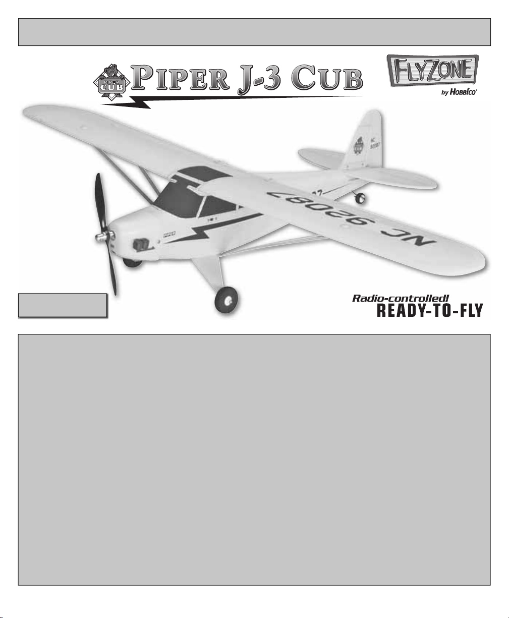
COMPLETE RTF AIRPLANE
™
REQUIRES:
8 “AA” Alkaline Batteries
Please retain this information for future reference.
ASSEMBLE ONLY WITH ADULT SUPERVISION
Please read through this instruction booklet to THOROUGHLY familiarize yourself with the assembly and fl ight characteristics
of this airplane before beginning to assemble the kit.
Please inspect all parts carefully before starting assembly! If any parts are missing, broken or defective, or if you have any
questions about the assembly or fl ying of this airplane, please call us at (217) 398-8970 and we’ll be glad to help.
WARRANTY
Hobbico® guarantees this kit to be free from defects in both material and workmanship at the date of purchase. This warranty
does not cover any component parts damaged by use or modifi cation. In no case shall Hobbico’s liability exceed the original cost
of the purchased kit. Further, Hobbico reserves the right to change or modify this warranty without notice.
In that Hobbico has no control over the fi nal assembly, no liability shall be assumed nor accepted for any damage resulting
from the use by the user of the fi nal user-assembled product. By the act of using the user-assembled product, the user accepts
all resulting liability.
If the buyers are not prepared to accept the liability associated with the use of this product, they are advised to return this kit
immediately in new and unused condition to the place of purchase.
To make a warranty claim send the defective part or item to Hobby Services at the address below:
Hobby Services
3002 N. Apollo Dr., Suite 1
Champaign IL 61822 USA
Include a letter stating your name, return shipping address, as much contact information as possible (daytime telephone
number, fax number, e-mail address), a detailed description of the problem and a photocopy of the purchase receipt. Upon
receipt of the package the problem will be evaluated as quickly as possible.
Entire Contents © Copyright 2007 Printed in China HCAZ2400 for HCAA24**
Page 2

PROTECT YOUR MODEL, YOURSELF
AND OTHERS; FOLLOW THESE
IMPORTANT SAFETY PRECAUTIONS
Your Piper J-3 Cub plane is not a toy, but rather
a sophisticated, working model that functions
very much like an actual airplane. Because of its
realistic performance, the model, if not assembled
and operated correctly, could possibly cause injury
to yourself and spectators or damage property.
We highly recommend that you get experienced,
knowledgeable help with assembly and during your
fi rst fl ights, to make your R/C modeling experience
totally enjoyable. You’ll learn faster and avoid risking
your model before you’re truly ready to solo. Your
local hobby shop has information about fl ying clubs
in your area whose membership includes qualifi ed
instructors. You can also contact the national Academy
of Model Aeronautics (AMA), which has more than
2,500 chartered clubs across the country. Instructor
training programs and insured newcomer training
are available through any one of these clubs.
Contact the AMA at the address or toll-free phone
number below.
Academy of Model Aeronautics
5151 East Memorial Drive
Muncie, IN 47302
(800) 435-9262
Fax: (765) 741-0057
or via the Internet at: www.modelaircraft.org
The R/C model hobby becomes more and more
enjoyable as your experience grows. Your chances
for success and graduation to higher levels are
very good if you take your time and follow the
assembly and fl ying instructions carefully and
completely. We hope you enjoy fl ying your Piper
J-3 Cub plane.
GLOSSARY
Aileron: Controls roll.
Electronic Speed Control (ESC): This unit controls
the speed of the motor.
Elevator: Controls the altitude.
Receiver: Translates inputs from the transmitter
and provides input to the control surfaces.
Rudder: Controls direction (yaw).
Motor: The motor rotates the prop to provide thrust.
Nickel-Metal Hydride (NiMH) Battery:
Rechargeable batteries which are used to power
the airplane. NiMH batteries are lighter and smaller
than most other types of rechargable batteries.
Transmitter (TX): This is the hand-held unit that sends
the signal to the control unit. Moving the sticks
controls direction, climb/descent, roll and speed.
TRAINER
SWITCH
THROTTLE TRIM
ELEVATOR TRIM
PRECAUTIONS
1. Assemble the plane according to the instructions.
Do not alter or modify the model. If you make any
modifi cations, you will void your warranty.
2. Tes t the operation of the model before each fl ight
to insure that all equipment is operating properly,
and that the model remains structurally sound.
3. Fly only on calm days (with wind speeds less
than 5 mph) and in large open areas free of trees,
people, buildings or any other obstacles.
Remember: Take your time and follow the instructions
to end up with a well-built model that is durable and
easy to fl y.
THROTTLE/
CONTROL STICK
RUDDER TRIM
2
RUDDER
RECEIVER
MOTOR
SERVO REVERSING
AIL
ELE THR RUD
REV
POWER
NOR
REVERSING SWITCHES
RUDDER, ELEVATOR
& AILERON SERVOS
ESC
ON/OFF
SWITCH
ELEVATOR/
AILERON
CONTROL STICK
AILERON TRIM
ON
POWER SWITCH
OFF
NIMH BATTERY
Page 3
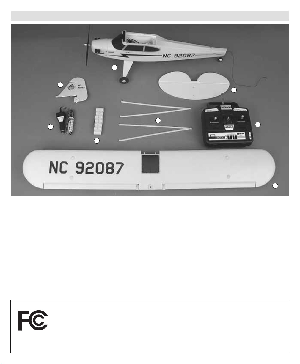
AIRFRAME PARTS AND HARDWARE
1
6
8
3
4
2
7
5
UNPACKING THE BOX
Check the parts against the list below. If any parts are damaged or missing, give us a call at: (217) 398-8970.
Part Name ................................................Qty.
❏ 1. Fuselage.......................................................1
❏ 2. Stabilizer .....................................................1
❏ 3. Peak Charger ..............................................1
❏ 4. 1100 mAh NiMH Battery ...........................1
❏ 5. Wing .............................................................1
❏ 6. Rudder ......................................................... 1
❏ 7. Transmitter .................................................. 1
❏ 8. Struts ............................................................ 1
[Not Shown: Extra propeller, screwdriver,
mounting screws (1-wing, 6-struts), wrench]
FCC REQUIREMENT
This device complies with Part 15 of the FCC Rules. Operation is subject to the following two
conditions: (1) This device may not cause harmful interference, and (2) This device must accept
any interference received, including interference that may cause undesired operation.
CAUTION: Changes or modifi cations to this product not expressly approved by
compliance may void the user’s authority to operate the equipment.
3
the party responsible for
Page 4
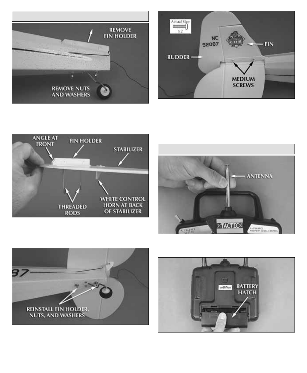
INSTALL THE FIN
❏ 1. Remove the two nuts and washers on the
bottom aft end of the fuselage. Then, remove the
fi n holder from the fuselage.
❏ 2. Insert the two threaded rods of the fi n holder
through the stabilizer, making sure that the white
control horn is on the bottom.
❏ 4. Remove the two screws in the fi n holder and
insert the fi n into the fi n holder. Reinstall the two
screws to secure the fi n to the holder. Be careful to
not overtighten the screws.
PREPARE THE TRANSMITTER
❏ 1. Install the antenna into the transmitter by
screwing it on until tight.
❏ 3. Reinstall the fi n holder with the stabilizer onto
the fuselage. Reinstall the two washers and the
two nuts on the threaded rods. Use the included
wrench to tighten the nuts, being careful to not
crush the foam.
❏ 2. The transmitter is the unit that controls your
airplane and requires of eight good quality “AA”
batteries. To install the batteries, remove the
battery hatch on the back of the transmitter.
4
Page 5
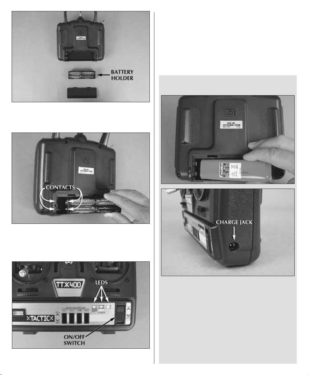
❏ 3. Pull the battery holder out of the transmitter
case and install eight new “AA” batteries, following
the diagram on the holder.
you informed of the amount of battery power
remaining during fl ying. When all three LEDs are
illuminated, it is safe to fl y. As battery power is
depleted, the green and yellow LEDs will go out.
When only the red LED is illuminated, land your
J-3 Cub and install fresh batteries.
OPTIONAL RECHARGEABLE
TRANSMITTER BATTERY
❏ 4. Insert the battery holder in the transmitter case
so that the two contacts on the battery holder align
with the contacts in the transmitter case. Reinstall
the battery hatch on the transmitter case.
❏ 5. Switch on the transmitter and check the LED
on the front of the transmitter. The LEDs keep
The Tactic 4-channel transmitter is equipped
with a charge jack that will allow you to
use a rechargeable NiCd battery pack and
charge it directly through the transmitter.
For a rechargeable pack that works with
this transmitter, use part number FUTM1450
Transmitter NiCd 9.6V 500mAh.
A charge lead and an appropriate charger will also
be required. For an economical multi-purpose
charger, use HCAP0100 R/C Multi-Charger. For
charge leads, use HCAP0101 Tx/Rx Charge leads.
5
Page 6

Caution:
•Do not mix old and new batteries.
• Do not mix alkaline, standard (carbon-zinc) or
rechargeable (NiCd) batteries.
• Non-rechargeable batteries are not to
be recharged.
• Only batteries with the same or equivalent
type as recommended are to be used.
• Batteries are to be inserted with the
correct polarity.
• Exhausted batteries are to be removed from
the transmitter.
• The supply terminals are not to be
short circuited.
CHARGE THE PLANE’S NIMH BATTERY
battery pack will plug in only one way. The LED
on the charger will glow continuously once the
battery is connected and charging has begun.
❏ 3. IMPORTANT! NEVER LEAVE A CHARGING
BATTERY UNATTENDED. ONLY CHARGE THE PIPER
J-3 CUB BATTERY WITH THE INCLUDED CHARGER.
DO NOT USE A WIND-UP TIMER CHARGER.
❏ 4. During charging, feel the battery every 5
minutes to see if it is starting to warm up. A warm
(but not hot) battery pack is a sign that the battery
is nearing a full charge. If the battery becomes hot,
disconnect it from the charger.
❏ 5. Once the battery reaches a full charge the
charger will start to beep and the LED will fl ash.
❏ 6. Unplug the battery pack from the charger
and the charger from the 12-volt power outlet in
your vehicle.
❏ 7. After each fl ight, remove the pack from
the airplane and allow it to cool completely
before recharging.
❏ 1. Plug the battery charger into a 12-volt power
outlet in a vehicle, placing the battery to be charged
outside the car, and away from fl ammables. NEVER
charge your airplane battery while driving or with
the vehicle engine running!
❏ 2. Plug the battery pack into the charger
connector. Be careful–do not force the plugs. The
BATTERY CHARGING PRECAUTIONS
❏ 1. Always remove the battery from your Piper J-3
Cub before charging.
❏ 2. Remember to check the temperature of
the battery every 5 minutes during charging.
If the battery becomes hot, unplug the battery
from the charger, even if the charger has not
stopped charging.
❏ 3. Charging the Piper J-3 Cub battery while
your car is running can be dangerous, because
it increases the chances of overcharging. For this
reason, you should never charge your Piper J-3
Cub battery while your car’s engine is running.
❏ 4. A properly cared for battery pack will last a
long time. If the battery pack is continually charged
while it is still hot, the life of the battery pack will
be shortened. WARNING: Misuse or malfunction
may overheat the battery and charger, resulting in
personal injury or damage to surroundings.
6
Page 7

BATTERY RECYCLING
ATTENTION: The product you have
purchased is powered by a rechargeable
battery. At the end of the battery’s
useful life, under various state and local
laws, it may be illegal to dispose of this
battery into the municipal waste system. Check
with your local solid waste offi cials for details in
your area for recycling options or proper disposal.
WARNING: This product contains a chemical known
to the State of California to cause cancer.
INSTALL THE WING
the wing forward, inserting the posts in the holes
on the fuselage. Fasten the wing to the fuselage with
the large screw. The screw should be tight enough
to hold the wing snug against the fuselage, yet not
crush the wing. Do not over-tighten.
❏ 1. The receiver is secured to the fuselage with hook
and loop material. Pull the receiver free and plug
the aileron servo lead from the wing into Channel
“1” with the white wire facing up (the channels are
numbered on the bottom of the receiver). Push the
receiver back onto the hook material.
❏ 2. At the front edge of the wing are two small posts.
Position the wing on the top of the fuselage and slide
❏ 3. Turn the plane over and attach the wing struts
to the battery tray using two small screws. The arm
of the wing strut that goes towards the front of the
wing is marked with an arrow. Attach the other end
of the wing struts to the wing using a small screw
at the back edge of the wing and a medium screw
at the front edge. Repeat this procedure forth e
other wing. Important: The Piper J-3 Cub must
never be fl own without the wing struts attached.
The wing struts help support the wing.
7
Page 8

RADIO ADJUSTMENT
❏ 2. Center the rudder, aileron, and elevator trim.
❏ 1. Switch on the transmitter. Make sure all three
LEDs are on. Open the battery hatch cover on the
bottom of the plane and insert the battery. Attach
the battery to the connector. Turn on the plane by
moving the switch on the left side of the fuselage.
CAUTION: Once the battery is connected to
the ESC and the plane is turned on, stay clear of
the propeller.
❏ 3. Install the rudder pushrod in the outer hole of
the control horn. Slide a pushrod retainer over the
pushrods to secure it.
❏ 4. Install the elevator pushrod in the outer hole
of the control horn. Slide a pushrod retainer over
the pushrod to secure it.
8
Page 9

❏ 5. With the transmitter and plane switched on,
center the elevator, rudder and aileron sticks and
trim levers. Use a straight edge to adjust the rudder
and elevator so that they are in the neutral position
and tighten the screws in the pushrod connectors.
❏ 1. When viewing the airplane from the aft end,
move the left control stick to the left. The rudder
must move to the left. If it does not, change the
position of the rudder servo reversing switch on
the transmitter. When the left stick is moved all
the way left, the trailing edge of the rudder should
move to the left 3/8" [9.5mm]. When the left stick
is moved all the way right, the trailing edge of the
rudder should move to the right 3/8" [9.5mm].
CHECK THE CONTROL THROWS
The throws are measured at the widest part of
the elevator and rudder. Adjust the position of
the pushrods at the servo arms and the control
horns to change the amount of throw. Moving the
pushrod out away from the center of the servo arm
or in on the control horn will increase the amount
the control surface moves.
❏ 2. By moving the right stick down, the elevator
must move up. If it does not, change the position
of the elevator servo reversing switch on the
transmitter. When the right stick is moved all the
way down (towards you), the trailing edge (back
edge) of the elevator should move up 1/2" [13mm].
When the right stick is moved all the way up (away
from you) the trailing edge of the elevator should
move down 1/2" [13mm].
9
Page 10

❏ 3. By moving the right control stick left, the left
aileron must move up and the right aileron must
move down. If they do not, change the position of
the aileron servo reversing switch on the transmitter.
When the right stick is moved all the way to the left,
the trailing edge of the left aileron at the inward
side should move up 3/16" [5mm]. When the right
side stick is moved all the way to the right, the left
aileron should move down 3/16" [5mm].
❏ 5. To start the motor, the throttle stick must fi rst
be “OFF”, all the way down when switching on
the transmitter and plane. Then move the stick all
the way up and hold it there for 5 seconds. Then
return the stick down. This will “arm” the motor.
The motor will now operate when the throttle stick
is moved up. NOTE: Arming the motor must be
done each time after the airplane has been turned
OFF! (Arming of the motor is a sefety feature that
prevents inadvertant starting of the motor if the
transmitter is switched on with the throttle stick in
any position other than full off.)
CHECK THE BALANCE OF THE MODEL
Note: Although your J-3 Cub comes balanced from
the factory, the balance point should be confi rmed
using the following procedure. This section is VERY
important and should NOT be omitted. A model
that is not properly balanced will be unstable and
possibly unfl yable.
❏ 4. The set screw in the prop adapter should be
checked and tightened before each fl ight.
❏ 1. After the battery pack is charged, open the battery
hatch. Insert the battery pack inside the fuselage. Do
not plug the battery pack into the connector inside
the fuselage. Close the battery hatch.
10
Page 11

TRAINER SYSTEM
❏ 2. Place marks on the bottom of the wing 1-1/2”
[38mm] and 1-3/4” [44mm] back from the front of the
wing, next to the left and right sides of the fuselage.
Turn the airplane right side up. Try to balance the
airplane on your fi nger tips, between the marks. This
is where the model should balance. We also found
that most of our test models balanced at this point
out of the box without having to add weight to the
nose or tail. If it does not balance at these marks,
weight will need to be added to the nose or tail. At
most hobby shops, you can purchase stick-on lead
weight made specifi cally for balancing airplanes.
The Tactic™ transmitter is equipped with a trainer
system that, when used with another Tactic or
Futaba® transmitter, can transfer airplane control
to a second pilot for learning purposes.
To use the trainer system, the FUTM4415 Trainer
Cord must be purchased. Connect the trainer
cord to the trainer port on the back of the Tactic
radio and the other end to another Tactic or Futaba
radio. The transmitter that came with the J-3 Cub
is the master radio and must always be turned on
during training. The second Tactic or Futaba radio
is the slave radio and must always be powered
off during training. Before fl ying the J-3 Cub
with the training function, confi rm that the slave
radio operates the control surfaces in the correct
directions. If not, adjust the servo reversing
switches on the slave radio accordingly.
When the trainer switch is activated and held
in the forward position on the master radio,
control will be transferred to the slave radio
11
Page 12

as long as the trainer switch is held on. When
the trainer switch is released, control will
immediately return to the master radio. The
pilot operating the master radio (instructor)
should be alert during the entire fl ight to regain
control of the aircraft as necessary.
NOTES ON USING THE TRAINER FUNCTION:
Choose an experienced pilot or an AMA
instructor to operate the master radio when
teaching a new modeler to fl y. During the fi rst
few fl ights, allow the instructor to take off and
land the model until the student is accustomed
to the fl ight characteristics of the J-3 Cub. When
the instructor brings the model to a safe altitude
and level fl ight, he or she can activate the
trainer switch to transfer control to the student
operating the slave radio. The student should
keep the instructor updated during training
about the intended fl ight direction and altitude.
Doing so will allow the instructor to quickly
recognize an error and correct it. Keep the J-3
Cub at a high altitude during training to provide
enough recovery time for the instructor to regain
control of the aircraft in the event of a mistake.
CHOOSE A GOOD FLYING SITE
The Piper J-3 Cub should be fl own only when the
wind speed is 5 mph or less. If the wind is calm or
very light, the Piper J-3 Cub will be docile and easy
to control. Also, fi nd an area clear of trees, power
lines and other structures. A fl ying fi eld for R/C
planes is best. Don’t fl y around groups of people,
especially children or within six miles of existing
R/C fl ying fi elds.
PREPARE FOR TAKEOFF
1. Find an open area free of buildings, trees, power
lines and people.
2. For your fi rst few fl ights, fl y only when the wind is
calm. After you are comfortable with the airplane,
you can fl y in winds that are no more than 5 miles
per hour. If fl own in stronger winds, the plane may
be blown down wind and not have enough power
to get back, when the battery gets low.
3. Make sure the battery pack is fully charged and that
the transmitter has fresh “AA” batteries installed.
4. If others are fl ying in the same area, make sure
that they are not using the same transmitting
frequency you are. The front of your transmitter
has a tag with a number on it (Channel 50, 72.790).
This is the channel number and frequency you
are using. If someone is on the same channel or
frequency, DO NOT switch on your transmitter
until they are fi nished fl ying.
FLYING THE J-3 CUB
Your transmitter controls the altitude, direction,
roll and speed of the airplane. The left stick
controls the speed and direction and the right
stick controls the altitude and roll.
When the battery power gets too low, the “Auto
Cut-Off” feature of the speed control provides an
extra degree of insurance. It reacts to low power
by pulsing the motor on and off, in effect saving
power for the receiver. That way your airplane goes
into a glide and you stay in control as you land.
If you have never fl own an R/C airplane before, we
recommend that you get help from an experienced
R/C pilot. Most R/C clubs have training programs that
will help you learn to fl y quickly. If you cannot fi nd
an experienced pilot to help you learn, the following
will help you get your airplane into the air.
1. First switch your transmitter power switch “ON.”
Be sure your left control stick on the transmitter is
all the way down.
2. Now pick up the airplane and switch the airplane
on. Caution: Keep your hands behind the propeller.
3. Arm the motor by moving the left control stick
all the way up. Hold the throttle lever here for the
count of 5. Then, move the stick back down. Now
when the stick is moved up, the propeller will start
to turn. The farther the stick is moved, the faster
the propeller will turn.
4. Range check your radio before each fl ight. Have
a helper hold the airplane. With the transmitter
antenna collapsed, walk 100 feet away from the
airplane, holding the transmitter with the antenna
pointing up. Move the control sticks, checking that
12
Page 13

the control surface responds. Also, turn the motor
on and check the range. If you still have control
of the airplane, it is safe to extend the transmitter
antenna and fl y the airplane. If you do not have
control of the plane, make sure the batteries in the
transmitter are fresh and the battery in the plane
is charged. Also, make sure the wire antenna is
extending out the back of the airplane.
5. With the throttle stick moved fully up, hand
launch the Piper J-3 Cub into the wind, at a slight
upward angle. Note: For the fi rst couple of fl ights,
we recommend having a helper hand launch the
airplane. After you become familiar with the fl ight
characteristics of the airplane, it can be fl own off a
hard surface instead of hand launched.
6. Pull the elevator stick (right stick) toward you
so that the plane climbs at a 20 to 30 degree angle.
Allow the airplane to climb a few seconds before
turning it.
7. When your airplane is moving away from you,
moving the aileron stick (right stick) to the left,
combined with a small amount of up elevator
(moving the right stick down), will make your plane
turn to the left. Moving the stick to the right with a
small amount of up elevator will make the airplane
turn to the right. To stop the turn, move the stick the
opposite direction until the airplane is fl ying level
and return the elevator stick to center. Caution: It
only requires a small amount of up elevator.
8. Because the transmitter is set up as if it and you
were sitting in the cockpit, when the airplane is
coming toward you, moving the right stick left
still causes left aileron, but your airplane goes to
your right. In short, you have to reverse the way
you control the ailerons. Here’s a good way to
familiarize yourself with the controls: When the
airplane is coming toward you, turn your body so
that you are facing the same direction the airplane
is going, looking over your shoulder at the airplane.
Now when you move the aileron stick left, the
plane will go to your left.
9. Now that you have gained some altitude, it is
time to trim the plane for straight, level fl ight. If
the airplane wants to climb when the right control
stick is released, move the elevator trim lever up
away from you. If the airplane wants to dive, move
the elevator trim lever down towards you. It should
require very little trim. Your goal is to have the
airplane fl y level with the elevator stick centered.
10. If the airplane wants to roll left or right, move
the aileron trim lever in the opposite direction the
plane wants to roll. Again, it should require very
little trim.
11. For beginner pilots, rudder is primarily used
for takeoff and landings. The ability to turn the
plane without roll is necessary to keep the plane
level during takeoffs and landings. Moving the left
control stick (rudder) to the left will cause the J-3
Cub to turn left. Moving this stick to the right will
cause the plane to turn right. If the plane wants to
turn with the left stick centered, move the rudder
trim lever opposite the direction the airplane is
turning. The airplane should be trimmed so that
if you take your hands off of the control stick,
the airplane will fl y straight and level on its own.
Having the airplane trimmed properly makes
fl ying much easier and more enjoyable.
12. Don’t let the airplane get too far away from
you. The farther away it is, the harder it is to see
what the airplane is doing.
13. When learning to fl y, it is best to keep the
airplane high enough so that if you make a mistake,
you have enough altitude to correct the mistake.
IT’S NOW TIME TO LAND
It’s a known fact among fellow R/C pilots that your
airplane will land. It is up to you as to where and
how it lands!
1. For your fi rst couple of fl ights we recommend that
you attempt to land with reserve battery power. For
added insurance, your Piper J-3 Cub comes with an
auto motor cut-off feature which reserves battery
power to the receiver for safe landings.
2. During your fi rst fl ight, while at a high altitude,
turn the motor off and notice how the Piper J-3
Cub reacts. This will give you an idea of how the
airplane will react during a landing. At this higher
atltitude, familiarize yourself with how the model
responds at low power and slower speeds as this
is how the model will fl y when landing.
13
Page 14

3. To land the Piper J-3 Cub, fl y down wind, past the
landing area. Gently turn into the wind and reduce
the throttle so that the airplane starts to come down.
Adjust the throttle as needed to reach the landing
area, but not fl y past it. Always land into the wind.
4. Just before landing, at about 1 foot above the
ground, apply a little up elevator to fl are (raise the
nose of the airplane). This will cause the airplane
to slow and settle to the ground.
Caution: If, during a rough landing, the propeller
on the Piper J-3 Cub should become jammed and
cannot rotate with the throttle in the run position,
the battery and speed control will become very
hot. Immediately move the throttle stick down to
stop the motor. If you fail to do this, the motor,
speed control and/or battery will be damaged.
AFTER THE FLIGHT
Switch off the airplane. Then, switch the transmitter
off. Unplug the battery from the airplane and
remove the battery from the battery compartment.
Allow the motor and battery to cool before
recharging. Check the airplane over to make sure
nothing has come loose or may be damaged.
REPAIRS
Even the best R/C pilots in the world damage their
airplanes every now and then. In the unfortunate
event that you damage your airplane, repairs are
fairly simple to make yourself. If there are any
cracks in the wing or fuselage, apply 6-minute
epoxy or white glue to the broken areas and hold
together with clear packaging tape. Let the glue
cure, leaving the tape in place for added strength.
REPLACEMENT PARTS LIST
To order replacement parts for your Piper J-3
Cub, use the order numbers listed. Replacement
parts are available only as listed. Replacement
parts are not available from Product Support,
but can be purchased from hobby shops or mail
order/Internet order fi rms. If you need assistance
locating a dealer to purchase parts, contact:
Product Support
Phone: 217-398-0007 Fax: 217-398-7721
E-mail: productsupport@hobbico.com
Before starting to build, take an inventory of this
kit to make sure it is complete and inspect the
parts to make sure they are of acceptable quality.
If you need assistance with assembly, contact
Product Support. When reporting defective or
missing parts, use the part names exactly as they
are written in the parts list.
Stock # ........... Description
GPMP7700 ......NiMH 8.4V 1100mAh Red 2-Pin
HCAA3950 ......Main Wing
HCAQ3851 .....Prop Assembly
HCAA3951 ......Cowl Assembly
HCAA3952 ......Decal Set
HCAA3953 ......Struts (2)
HCAA3954 ......Motor Mount
HCAA3955 ......Main Landing Gear
HCAA3956 ......Tail Assembly
HCAA3957 ......Battery Hatch Door
HCAA3958 ......Fuselage w/Pushrods
HCAG1053 ......Motor 380
GPMM7700 .....12V Peak Charger 600-1100mAh 2-Pin
HCAQ3501 .....Propeller (2)
HCAA3959 ......Tail Wheel Assembly
HCAA3960 ......Firewall
HCAA3913 ......Control Horn Set
HCAA3961 ......Wing Screws
HCAA3962 ......Pushrod/Clevis
TACM0100 ......TSX100 Micro Servo
TACM5100 ......Servo Gear Set TSX100
TACM5101 ......Servo Arms TSX100
TACM4401 ......Antenna TX TTX400
TACM4402 ......Battery Door TX TTX400
TACL6036 ........TRX600 Receiver 72.510FM Channel 36
TACL6038 ........TRX600 Receiver 72.550FM Channel 38
TACL6042 ........TRX600 Receiver 72.630FM Channel 42
TACL6044 ........TRX600 Receiver 72.670FM Channel 44
TACL6046 ........TRX600 Receiver 72.710FM Channel 46
TACL6050 ........TRX600 Receiver 72.790FM Channel 50
TACJ14** ......... TTX400 Transmitter
TACL4036 ........Transmitter Crystal 72.510FM Ch 36
TACL4038 ........Transmitter Crystal 72.550FM Ch 38
TACL4042 ........Transmitter Crystal 72.630FM Ch 42
TACL4044 ........Transmitter Crystal 72.670FM Ch 44
TACL4046 ........Transmitter Crystal 72.710FM Ch 46
TACL4050 ........Transmitter Crystal 72.790FM Ch 50
TACM4403 ......Transmitter Battery Holder
TACM6600 ......TSC600 Electronic Speed Control
14
Page 15

OTHER ITEMS AVAILABLE
DIABLO EDF JET TRAINER RTF
DIABLO EDF JET TRAINER RTF
Wingspan: 40.25 in (1020 mm)
Wing Area: 320 in2 (20.6 dm2)
Length: 39 in (995 mm)
Includes: Tactic™ 4-channel radio, receiver,
Don’t just learn to fl y: learn to fl y a ducted fan model — without fear! The
Diablo’s sleek military styling gives it the look of a super-quick jet...but it
actually handles as gently as a trainer. It’s virtually fl ight-ready right out of the
box, with a radio and power system already installed. And as your fl ying skills
grow, the Diablo grows with you — with special option parts available that give
this exciting electric jet extra speed and agility!
The Diabolo is molded from advanced AeroCell(tm) foam. It’s tough enough to take abuse, light enough for electric fl ight...and
factory-fi nished for great looks. The proven HyperFlow(tm) ducted fan system supplies incredible static thrust for unparalleled
fl ight speeds and jet performance. And FlyZone tips the scales for top-of-the-line fl ight by including a 3S 11.1V 1500mAh LiPo
battery pack — delivering more power than similarly sized NiMH packs. HCAA28**
servos, speed control, HyperFlow™
ducted fan system, ElectriFly™ 3S 11.1V
1500mAh LiPo battery pack, ElectriFly
balancing charger w/AC & DC adapters
Requires: 8 “AA” alkaline batteries
™
Main Rotor Span: 20.75 in. (528mm)
Height: 8.125 in. (206mm)
Length: 23 in (584mm)
Weight: 16.5 oz. (468 g)
Requires: 8 “AA” batteries
Fully assembled, test-fl own at the factory, fun indoors or out, and ready for 3D aerobatics - that’s the Axe CP RTF! You can fl y inverted
with ease and perform virtually any stunt you can imagine, without adding a single upgrade. The blades are symmetrical, covered and
ideal for aerobatics and inverted hovering. The composite 120° swash plate is larger and stronger than other minis – a big plus for
durability. Swift, precise, powerful eCCPM control is installed and ready to take you to the cutting edge of 3D maneuvers. Training gear
and a “how-to” DVD help get you started. Choose from six canopy color schemes. HMXE04**
15
Page 16

OTHER ITEMS AVAILABLE
Wingspan: 68.5 in (1740 mm)
Wing Area: 722 in² (46.6 dm²)
Weight: 7-8.5 lb (3175-3855 g)
Wing Loading: 22-27 oz/ft² (68-83 g/dm²)
Length: 56 in (1410 mm)
Includes: 6EXA computer radio w/3 servos & trainer system,
PA-2 fl ight stabilization system, electronic speed
control, RimFire™ 42-50-800 out-runner brushless
motor, APC 10x5E prop, RealFlight™ NexSTAR
simulator software and interface
Requires: (2) 9.6V 3600mAh NiMH batteries, peak charger
The ultimate electric fl ight training model.
Success is guaranteed!
Just as the NexSTAR 46 forever changed the perception of glow-powered ready-to-fl y trainers, the NexSTAR EP is doing the same
for electrics. It has all the innovations of the original NexSTAR, offering more assistance for fi rst-time pilots than any other plane.
And motor power means the NexSTAR EP is also the cleanest and quietest way to learn to fl y!
The included Futaba® 6EXA radio is the perfect fl ight system to start and stay with. It doubles as the controller for the supplied
NexSTAR EP CD ROM fl ight simulation software — so that the skills you learn while practicing at your PC translate directly into
improved ability at the fl ying fi eld. And, it has a built-in trainer system so you can share control with an instructor until you’re
comfortable fl ying solo.
For power, Hobbico includes the ElectriFly™ RimFire™ 42-50-800 out-runner brushless motor, which rivals glow engines for
performance. And numerous patented design features — such as PivotFlex™ wing mounting, the Easy Align™ tail mounting
system, and SnapGear™ quick landing gear mounts — make perfect fi nal assembly a sure thing. HCAA09**
Learn more about the NexSTAR EP (including how Hobbico literally guarantees your success)
by visiting www.hobbiconexstar.com today!
 Loading...