

Page 1

ASSEMBLE ONLY WITH ADULT SUPERVISION
Please read through this instruction booklet to THOROUGHLY familiarize yourself with the assembly and flight characteristics of this
airplane before beginning to assemble the kit.
Please inspect all parts carefully before starting assembly! If any parts are missing, broken or defective, or if you have any questions
about the assembly or flying of this airplane, please call us at (217) 398-8970 and we’ll be glad to help.
WARRANTY
Hobbico®guarantees this kit to be free from defects in both material and workmanship at the date of purchase. This warranty does not
cover any component parts damaged by use or modification. In no case shall Hobbico’s liability exceed the original cost of the
purchased kit. Further, Hobbico reserves the right to change or modify this warranty without notice.
In that Hobbico has no control over the final assembly, no liability shall be assumed nor accepted for any damage resulting from the use
by the user of the final user-assembled product. By the act of using the user-assembled product, the user accepts all resulting liability.
If the buyers are not prepared to accept the liability associated with the use of this product, they are advised to return this kit
immediately in new and unused condition to the place of purchase.
To make a warranty claim send the defective part or item to Hobby Services at the address below:
Hobby Services
3002 N. Apollo Dr., Suite 1
Champaign IL 61822 USA
Include a letter stating your name, return shipping address, as much contact information as possible (daytime telephone number, fax
number, e-mail address), a detailed description of the problem and a photocopy of the purchase receipt. Upon receipt of the package
the problem will be evaluated as quickly as possible.
CCOMPLETE R
OMPLETE R
TF
TF
AIRPLANE
AIRPLANE
Requires 8 (AA) Alkaline
Batteries (not included)
Quiet Electric Flight
Radio-Controlled Model
Entire Contents © Copyright 2004 HCAZ0070 for HCAA1981 V1
™
™
Printed in China
Page 2

Your Aero Voyager plane is not a toy, but rather a
sophisticated, working model that functions very much
like an actual airplane. Because of its realistic
performance, the model, if not assembled and operated
correctly, could possibly cause injury to yourself and
spectators or damage property.
We highly recommend that you get experienced,
knowledgeable help with assembly and during your
first flights, to make your R/C modeling experience
totally enjoyable. You’ll learn faster and avoid risking
your model before you’re truly ready to solo. Your local
hobby shop has information about flying clubs in your
area whose membership includes qualified instructors.
You can also contact the national Academy of Model
Aeronautics (AMA), which has more than 2,500
chartered clubs across the country. Instructor training
programs and insured newcomer training are available
through any one of these clubs.
Contact the AMA at the address or toll-free phone
number below.
Academy of Model Aeronautics
5151 East Memorial Drive
Muncie, IN 47302
(800) 435-9262
Fax: (765) 741-0057
or via the Internet at: http://www.modelaircraft.org
1. Assemble the plane according to the instructions. Do
not alter or modify the model. If you make any
modifications, you will void your warranty.
2. Te st the operation of the model before each flight to
insure that all equipment is operating properly, and that
the model remains structurally sound.
3. Fly only on calm days (with wind speeds less than 5
mph) and in large open areas free of trees, people,
buildings or any other obstacles.
Remember: Take your time and follow the instructions
to end up with a well-built model that is durable and
easy to fly.
The R/C model hobby becomes more and more
enjoyable as your experience grows. Your chances for
success and graduation to higher levels are very good if
you take your time and follow the assembly and flying
instructions carefully and completely. We hope you
enjoy flying your Aero Voyager plane.
Electronic Speed Control/Receiver (ESC/RX): This unit
controls the motors and control surfaces.
Ruddervator (V-Tail): Controls altitude and direction.
Motors: The motors rotate the props to provide thrust.
Nickel-Metal Hydride (NiMH) Battery: Rechargeable
batteries which are used to power the airplane. NiMH
batteries are lighter and smaller than most other types of
rechargable batteries.
Transmitter (TX): This is the hand-held unit that sends
the signal to the control unit. Moving the stick controls
the direction and climb/decent. The throttle lever
controls the motors.
GLOSSARY
PRECAUTIONS
PROTECT YOUR MODEL, YOURSELF
AND OTHERS.
FOLLOW THIS IMPORTANT SAFETY
PRECAUTION
2
Page 3

3
AIRFRAME PARTS AND HARDWARE
Part Name Qty.
❏ 1. Fuselage/Tail Boom ......................................1
❏ 2. 600 mAh NiMH Battery ................................1
❏ 3. Charger ........................................................1
❏ 4. Wing ............................................................1
❏ 5. V-Tail ............................................................1
❏ 6. Transmitter ....................................................1
❏ 7. Wrench for Tightening Nuts ..........................1
❏ 8. Nuts ..............................................................2
❏ 9. Tail Skid........................................................1
❏ 10. Rubber Bands................................................4
❏ Spare Propellers (Not Shown in Photo) ........2
❏ Decal (Not Shown in Photo) ........................1
❏ Instructional DVD (Not Shown in Photo) ......1
UNPACKING THE BOX
Check the parts against the list below.
If any parts are damaged or missing, give us a call at: (217) 398-8970.
1
5
2
3
10
9
7
4
8
6
Page 4
❏
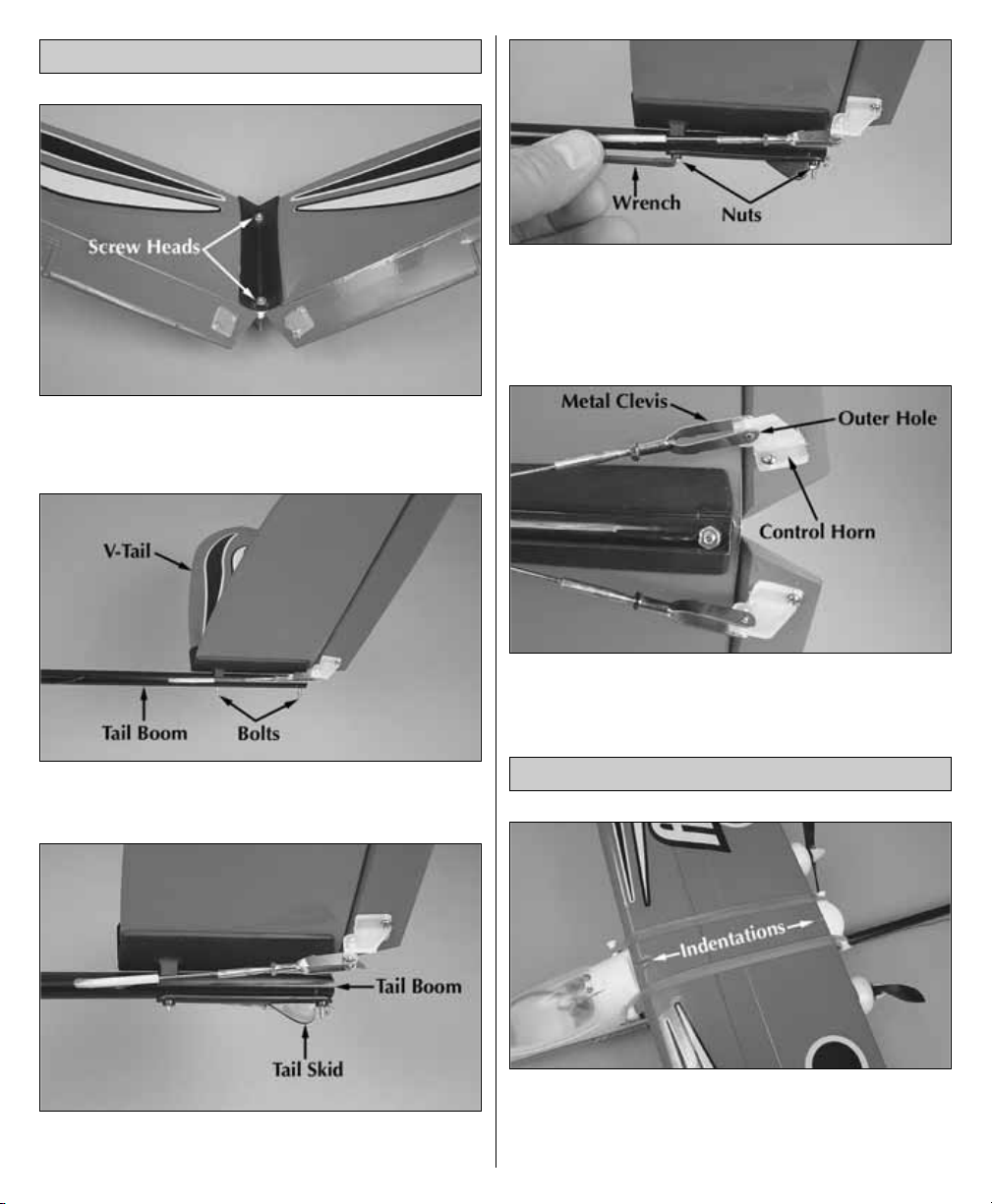
1. Apply the decals to the top of the airplane surfaces
as seen on the box. (The top of the V-tail has the two screw
heads showing.)
❏
2. Insert the mounting bolts of the V-tail through the
holes from the top of the tail boom as shown in the photo.
❏
3. Install the tail skid over the mounting bolts. Make sure
the tail skid is pointing down and to the rear of the airplane.
❏
4. Place the two nuts on the mounting bolts that
extend through the bottom of the tail boom as shown in
the photo. Using the included wrench, tighten the nuts
firmly but do not overtighten. You have now completed
the assembly of the V-tail.
❏
5. Spread the metal clevises apart and insert the
clevis pin in the outer hole of the control horns. Make
sure the clevis snaps closed over the control horn.
❏
1. Position the wing, centered on the fuselage. The
two indentations on the top of the wing should be
aligned with the center of the fuselage. Secure the wing
with two rubberbands.
INSTALL THE WING
INSTALL THE V-TAIL
4
Page 5

❏ 2. Attach two additional rubberbands, crossing them
over the top of the wing.
❏
1. The transmitter that controls your airplane requires
power, in the form of eight “AA” batteries. To install the
batteries loosen the screw on the bottom of the
transmitter and remove the battery hatch.
❏
2. Pull the battery
holder out of the
transmitter case and
install eight new “AA”
batteries in the holder
following the diagram
on the holder.
❏
3. Insert the battery holder in the transmitter case so
that the two contacts on the battery holder align with
the contacts in the transmitter case. Reinstall the battery
hatch on the transmitter case and tighten the screw.
❏
4. Switch on the transmitter and check the LED on
the front of the transmitter. If the green light is on, it is
safe to fly. If the red light is on or flashing, you need to
install fresh batteries.
❏
5. On the front of
the transmitter are
three switches. The
two switches on the
left are for reversing
the direction of the
servos. The mixing
switch on the right
turns the V-tail mixing
on or off. Set ch.1
switch to NOR, ch.2 to
REV and mix to ON.
Caution:
•Do not use rechargeable (NiCd) batteries.
•Do not mix old and new batteries.
•Do not mix alkaline, standard (carbon-zinc) or
rechargeable (NiCd) batteries.
PREPARE THE TRANSMITTER
5
Page 6

❏ 1. Plug the battery charger into a 12-volt power
outlet
in a vehicle, placing the charger and battery outside the
car, away from flammables.
❏
2. Plug the battery pack into the charger connector.
Be careful - the battery pack will plug in only one way.
❏ 3. Rotate the timer knob on the charger to 30
minutes. Make sure the red light comes on.
❏ 4. IMPORTANT! NEVER LEAVE A CHARGING
BATTERY UNATTENDED.
❏
5. During charging, feel the battery every 5 minutes
to see if it is starting to warm up. A warmed up (but not
hot) battery pack is a sign that it is fully charged. Once
the pack is warm, disconnect it from the charger.
Depending on how much charge was already in the
pack, you may have to disconnect the battery early.
❏
6. Always disconnect the charger from the 12-volt
power outlet in your vehicle when finished charging.
❏
7. After each flight, completely discharge the battery
and remove the battery pack from the airplane and
allow it to cool completely before recharging. To fully
discharge your airplane battery, run the motors at high
speed until they stop.
❏
1. Be careful to avoid overcharging the battery! When
you plug the battery into the charger there is no way to
know how much charge is left in the battery (unless you
have just completed a flight in which the battery was run all
the way down or have fully discharged the battery). If you
put too much charge into the battery, it will get very hot. This
may result in melting the plastic battery cover, causing the
cells to vent and damaging the charger! Always remove the
battery from your Aero Voyager before charging.
❏
2. Remember to check the temperature of the battery
every 5 minutes during the charge. Unplug the battery
as soon as it warms up (before it gets hot), even if the
timer has not yet run down.
❏
3. Charging the Aero Voyager battery while your car’s
engine is running can be dangerous, because it
increases the chances of overcharging. For this reason,
you should never charge your Aero Voyager battery
while your car’s engine is running.
❏
4. If your battery is not completely discharged before
charging, the charging time may take less than 30 minutes.
Again, only let the battery get warm to the touch – not hot.
❏
5. If you use a different battery charger, charge this
battery pack only at a maximum charge rate of 1/2 amp.
A higher charge rate will charge the battery pack too
quickly and heat up the wires.
BATTERY CHARGING PRECAUTIONS
CHARGE THE PLANE’S NIMH BATTERY
6
Page 7

❏
6. A properly cared for battery pack will last a long
time. If the battery pack is continually overcharged or
charged at too high of a rate, the life of the battery pack
will be shortened.
WARNING: Misuse or malfunction may overheat the
battery and charger, resulting in personal injury or
damage to surroundings.
ATTENTION: The product you have
purchased is
powered by a
rechargeable battery. At the end of the
battery’s useful life, under various state
and local laws, it may be illegal to
dispose of this battery into the
municipal waste system. Check with your local solid
waste officials for details in your area for recycling
options or proper disposal.
WARNING: This product contains a chemical known to
the State of California to cause cancer.
Note: This section is VERY important and must NOT be
omitted! A model that is not properly balanced will be
unstable and possibly unflyable.
❏ 1. After the battery pack is charged, open the
battery
hatch canopy. Insert the battery pack inside the
fuselage. Do not plug the battery pack into the
connector inside the fuselage. Close the canopy.
❏
2. Place marks on the bottom of the wing 2-3/16"
[56mm] and 2-3/8" [60mm] back from the front of the
wing, next to the left and right sides of the fuselage. Turn
the airplane right side up. Try balancing the airplane on
your finger tips, between these marks. This is where the
model should balance. We also found that most of our
test models balanced at this point without having to add
weight to the nose or tail. If it does not balance at these
marks, weight will need to be added to the nose or tail.
At most hobby shops, you can purchase stick-on lead
weight made specifically for balancing airplanes.
Your transmitter controls the altitude, direction and
speed of the plane. The right stick controls the altitude
and direction and the lever on the top of the transmitter
controls the speed.
❏
1. First switch on the transmitter and make sure the
green light is on.
HOW DOES THE AERO VOYAGER WORK?
CHECK THE BALANCE OF YOUR MODEL
BATTERY RECYCLING
7
Page 8

❏ 2. Open the battery canopy and plug the
battery pack
into the plug in the fuselage.
❏
3. Close and latch the canopy.
❏
4. Move the power switch back to the “ON” position.
CAUTION: Stay clear of the propellers once the
battery pack is plugged in and the switch is turned on.
❏
1. Center the trim levers on the front of the transmitter.
❏
2. Place a straightedge across the bottom of the V-tail. It
should be flat all the way across. If it is not, unclip the clevis
from the control horn and use the included wrench to
loosen the nut securing the clevis. Now the clevis can be
rotated in or out. Reattach the clevis to the control horn and
CHECK THE CONTROLS
8
Page 9

check the V-tail again. This adjustment may require several
adjustments before it is correct. Tighten the nut against the
clevis with the wrench. Do not overtighten.
❏
3. Check both the left and right side of the V-tail. NOTE:
If the V-tail cannot be adjusted correctly by rotating the
clevises, see page 11 for details on adjusting the servos.
❏
4. Hold the Aero Voyager while you move the right stick
on the transmitter back. The control surfaces on the V-tail
should both move up. This will cause the plane to climb.
❏
5. Moving the right stick forward will cause the
control surfaces to move down. This will cause the
plane to descend.
❏
6. Move the right stick on the transmitter to the right. The
left control surface will go up and the right control surface
will go down. The plane will turn to the right.
❏
7. Move the right stick on the transmitter to the left.
The left control surface will go down and the right
control surface will go up. The plane will turn to the left.
❏
8. To start the motors, the throttle lever must first be
“OFF”, all the way to the left when switching on the
transmitter and plane. Then move the lever all the way to
the right and hold it there for 5 seconds. Then return the
lever to the left. This will “arm” the motors. The motors
will now operate when the throttle lever is moved to the
right. NOTE: Arming the motors will need to be done
each time after the transmitter has been turned OFF!
The Aero Voyager should be flown only when the wind
speed is 5 mph or less. If the wind is calm or very light,
the Aero Voyager will be docile and easy to control.
Also, find an area clear of trees, power lines and other
structures. A flying field for R/C planes is best. Don’t fly
around groups of people, especially children or within
6 miles of existing R/C flying fields.
CHOOSE A GOOD FLYING SITE
9
Page 10

1. Find an open area free of buildings, trees, power lines
and people.
2. For your first few flights, fly only when the wind is
calm. After you are comfortable with the airplane, you
can fly in winds that are no more than 5 miles per hour.
If flown in stronger winds, the plane may be blown down
wind and not have enough power to get back to you.
3. Make sure the battery pack is fully charged and that
the transmitter has fresh “AA” batteries installed.
4. If others are flying in the same area, make sure that
they are not using the same channel radio system you
are. The front of your transmitter has a tag with a number
on it (i.e. 1 through 6 and 26.995 through 27.255). This
is the channel number and frequency you are using. If
someone is on the same channel or frequency, DO NOT
switch on your transmitter until they are finished flying.
5. Range check your radio before each flight. Switch on
the transmitter and then switch on the airplane. Have a
helper hold the airplane. With the antenna collapsed,
walk 100 feet away from the airplane. Move the control
stick, checking that the control surfaces respond. Also
turn the motors on and check the range. If you still have
control over the airplane, it is safe to extend the antenna
and fly the airplane. If you do not have control of the
plane, make sure the batteries in the transmitter are
fresh
and the battery in the plane is charged. Also, make sure
the wire antenna is extending out the back of the plane.
1. Have an assistant help with the launch. Arm the motors
by moving the throttle lever to the right for 5-seconds
then back to the left. Start the motors by moving the
throttle lever to the right. Have your assistant launch
the plane into the wind. It is not necessary to throw the
plane really hard. Just a nice, smooth and level toss
into the wind is more than enough.
2. Move the right stick toward you so that the plane
climbs at a 20 to 30 degree angle. Allow the plane to
gain some altitude and air speed before turning.
3. To turn the Aero Voyager, move the right stick to the
left or right slightly. The more you move the stick, the
tighter the turn will be. To stop the turn, move the
stick the opposite direction until the plane is flying
straight. You may need to add a little up elevator
(move the stick back toward you) to maintain level
flight in the turn.
4. When the plane is coming toward you, moving the right
stick left still causes the plane to turn left, but it appears
to turn to the right. In short, you have to reverse the way
you control the right stick. A good way to familiarize
yourself with the controls is when the plane is coming
toward you, turn your body so that you are facing the
same direction the plane is going, looking over your
shoulder at the plane. Now when you move the right
stick left the plane will go to the left.
5. Don't let the airplane get too far away from you. The
farther away it is, the harder it is to see what the plane
is doing.
6. When learning to fly, it is best to keep the plane high
enough so that if you make a mistake, you have
enough altitude to correct the mistake.
It’s a known fact among fellow R/C pilots that your airplane
will land. It is up to you as to where and how it lands.
1. For your first couple of flights we recommend that
you attempt to land before the motors stop. Your Aero
Voyager comes with an auto cut-off feature which
reserves battery power for safe landings.
2. During your first flight, while at a high altitude, turn the
motors off and notice how the Aero Voyager reacts. This will
give you an idea of how the plane will react during landing.
3. To land the Aero Voyager, fly down wind, past the
landing area a few yards. Gently turn into the wind and
turn the motors off. The plane will start to come down.
If it appears that the Aero Voyager will be short of the
landing area, turn the motors back on for a couple of
seconds to lengthen your approach.
4. As the Aero Voyager slowly descends, use the right stick
to control the direction. The Aero Voyager will just about
land itself. All you need to do is control its direction.
IT’S NOW TIME TO LAND
FLYING THE AERO VOYAGER
PREPARE FOR TAKEOFF
10
Page 11

Switch off the airplane. Then, switch the transmitter off.
Unplug the battery from the plane and remove it from
the battery compartment. Allow the motors and battery
to cool before recharging. Check the plane over to make
sure nothing has come loose or may be damaged.
To order replacement parts for your Aero Voyager, use the
order numbers in the list below. Replacement parts are
available only as listed. Replacement parts are not
available from Product Support, but can be purchased from
hobby shops or mail order/Internet order firms. If you need
assistance locating a dealer to purchase parts, contact:
Product Support
Phone: 217-398-0007
Fax: 217-398-7721
E-mail: productsupport@hobbico.com
Before starting to build, take an inventory of this kit to
make sure it is complete and inspect the parts to make
sure they are of acceptable quality. If any parts are
missing or are not of acceptable quality, or if you need
assistance with assembly, contact Product Support.
When reporting defective or missing parts, use the part
names exactly as they are written in the parts list.
Stock # Description
HCAA3413 Main Wing Kit
HCAA3414 Tail Assembly Kit
HCAA3415 Decals
HCAA3416 Fuse Set w/Pushrods
HCAA3417 Servo Hatch Door
HCAA3507 Canopy (Hatch)
HCAA3510 Motor Pod
HCAG1012 Motors (2)
HCAM7024 Battery NiMH
HCAM7106 TX Antenna
HCAP9918 12V Field Charger
HCAQ3303 Propellers (4)
Even the best R/C pilots in the world damage their planes
every now and then. In the unfortunate event that you
damage your airplane, repairs are fairly simple to make
yourself. If there are any cracks in the wing or fuselage,
apply 6-minute epoxy or white glue to the broken area
and hold together with clear packaging tape. Let the glue
cure, leaving the tape in place for added strength.
❏ 1. Remove the four screws that hold the servo hatch
on the bottom of the fuselage.
❏ 2. Remove the hatch. The decals may need to be
trimmed from around the hatch to allow it to be removed.
❏ 3. Switch on the transmitter, plug the motor battery
into the connector inside the fuselage and switch on the
plane. CAUTION: Stay clear of the propellers.
SERVO ADJUSTMENT
REPAIRS
REPLACEMENT PARTS LIST
AFTER THE FLIGHT
11
Page 12

❏ 4. Center the trims on the transmitter as shown on
page 8. Check that the servo arms are centered on the
servos. If they are not, remove the servo arm screw,
remove the servo arm and reinstall it centered on the
servo and reinstall the servo arm screw.
❏ 5. Loosen the nut on the clevis and rotate the clevis
to center it on the threaded pushrod end. Re-attach the
clevis to the V-tail.
❏ 6. Determine which servo controls the surface that
requires adjustment. Loosen the machine screw in the
pushrod connector on the servo arm.
❏ 7. Adjust the V-tail so that it is flat as explained on
page 8. Retighten the machine screw in the pushrod
connector and tighten the nut against the clevis. Reinstall
the servo hatch and install the four screws to secure it to
the fuselage.
❏ 8. Switch the plane off, then the transmitter.
Disconnect the motor battery.
ALSO AVAILABLE
DTXD20**
DuraTrax
®
Evader™ST Ready-to-Run
Check it out and you’ll agree: nothing can touch the 2WD
Evader ST electric ready-to-run stadium truck for
convenience, set-up ease, performance extras or
toughness. It arrives assembled and painted, with a 20-turn
Photon Speed™motor, Sprint™electronic speed control,
and a DuraTrax 2-channel radio system made by Futaba®.
Built-in “extras” include: slipper clutch, ball diff, ball
bearings, steel universal drives, FREE video and still more.
Requires only a 6-7 cell NiCd and charger.
 Loading...