

Page 1
ASSEMBLE ONLY WITH ADULT SUPERVISION
Please read through this instruction booklet to THOROUGHLY familiarize yourself with the assembly and flight
characteristics of this airplane before beginning to assemble this model. Please inspect all parts carefully before
starting assembly! If any parts are missing, broken or defective, or if you have any questions about the assembly
or flying of this airplane, please call us at (217) 398-8970 and we’ll be glad to help.
WARRANTY
Hobbico
®
, Inc. guarantees this kit to be free from defects in both material and workmanship at the date of
purchase. This warranty does not cover any component parts damaged by use or modification. In no case shall
Hobbico’s liability exceed the original cost of the purchased model. Further, Hobbico reserves the right to change
or modify this warranty without notice. In that Hobbico has no control over the final assembly, no liability shall
be assumed nor accepted for any damage resulting from the use by the user of the final user-assembled product.
By the act of using the user-assembled product, the user accepts all resulting liability. If the buyers are not
prepared to accept the liability associated with the use of this product, they are advised to return this kit
immediately in new and unused condition to the place of purchase.
To make a warranty claim send the defective part or item to Hobby Services at the address below:
Include a letter stating your name, return shipping address, as much contact
information as possible (daytime telephone number, fax number, e-mail address),
a detailed description of the problem and a photocopy of the purchase receipt.
Upon receipt of the package the problem will be evaluated as quickly as possible.
Requires 8 “AA” Batteries
(not included)
Entire Contents © Copyright 2006 Printed in China
HCAZ3001 for HCAA1961 V1.2
™
™
Hobby Services
3002 N. Apollo Dr. Suite 1
Champaign IL 61822
USA
READ THROUGH THIS MANUAL BEFORE STARTING
CONSTRUCTION. IT CONTAINS IMPORTANT
INSTRUCTIONS AND WARNINGS CONCERNING
THE ASSEMBLY AND USE OF THIS MODEL.
Champaign, Illinois
Page 2
Your SkyFly should not be considered a toy, but rather a
sophisticated, working model that functions very much
like a full-size airplane. Because of its performance
capabilities, the SkyFly, if not assembled and operated
correctly, could possibly cause injury to yourself or
spectators and damage to property.
We highly recommend that you get experienced
knowledgeable help with assembly and during your
first flights. This will make your modeling experience
more enjoyable. You’ll learn faster and avoid risking
your model before you are truly ready to fly solo. Your
local hobby shop has information about flying clubs in
your area whose membership includes qualified
instructors. You can also contact the Academy of Model
Aeronautics (AMA), which has more than 2,500
chartered clubs across the country. Instructor training
programs and insured newcomer training are available
through any one of these clubs.
Contact the AMA at the address or toll-free number below.
Academy of Model Aeronautics
5151 East Memorial Drive
Muncie, IN 47302-9252
Tele. (800) 435-9262
Fax (765) 741-0057
Or via the Internet at: www.modelaircraft.org
Assemble the plane according to instructions. DO
NOT alter or modify the model. If you make any
modifications, you void your warranty.
Test the operation of the model before each flight to
insure that all equipment is operating properly and that
the model remains structurally sound.
Fly only on calm days (with wind speeds less than
5mph) and in large open areas free of trees, people,
buildings, or any other obstacles.
Remember: Take your time and follow the instructions
to end up with a well-built model that is durable and
easy to fly.
The R/C model hobby becomes more and more
enjoyable as your experience grows. Your chances for
success and graduation to higher levels are very good if
you take your time and follow the assembly and flying
instructions carefully and completely. We hope you
enjoy flying your SkyFly airplane.
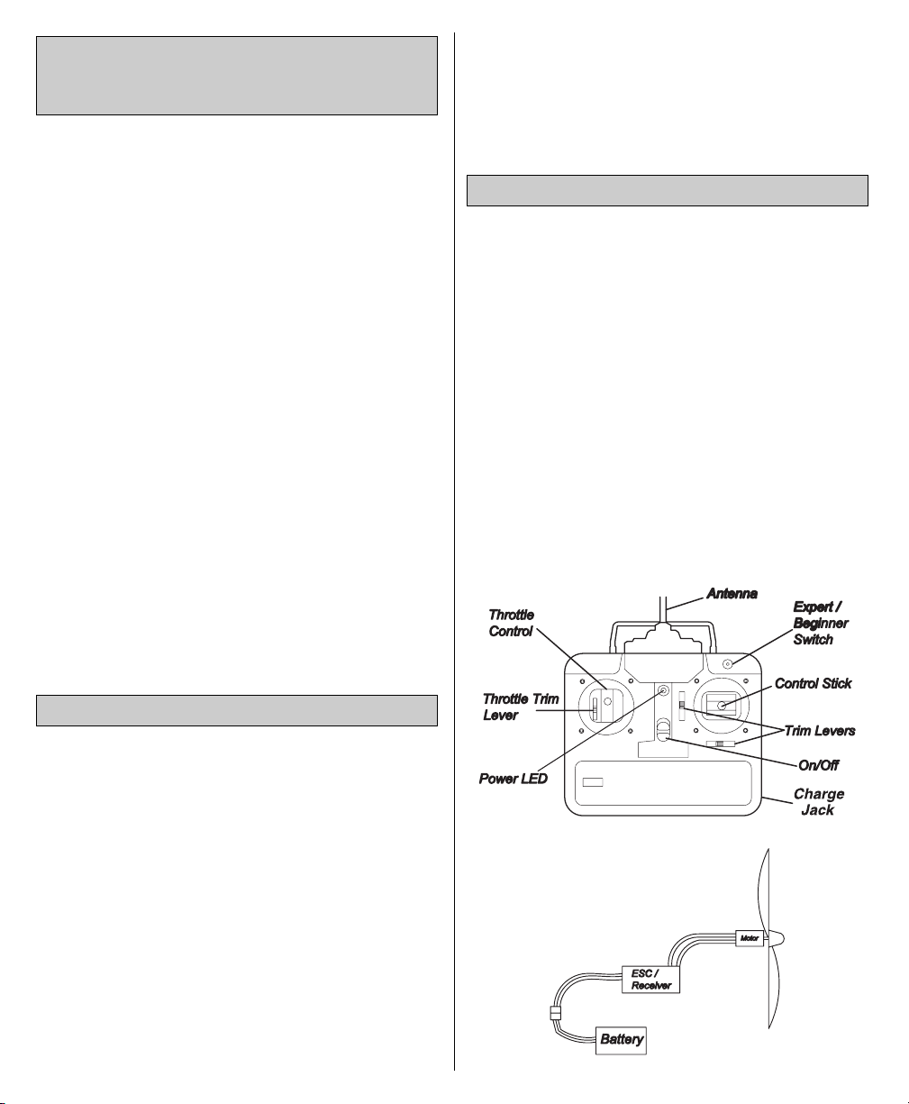
Electronic Speed Control / Receiver (ESC / RX) – This unit
controls the speed of the motor and control surfaces.
Elevator – Controls altitude
Rudder – Controls direction
Nickel – Metal Hydride (NiMH) Battery – Rechargeable
batteries which are used to power the airplane. NiMH
batteries are lighter and smaller that most other types of
rechargeable batteries.
Transmitter (TX) – This is the hand-held unit that sends
the signal to the control unit, or RX. Moving the sticks
controls speed, altitude and direction.
GLOSSARY
PRECAUTIONS
PROTECT YOUR MODEL, YOURSELF
AND OTHERS. FOLLOW THESE
IMPORTANT SAFETY PRECAUTIONS
2
Page 3
3
AIRFRAME PARTS AND HARDWARE
1
2
3
4
5
6
7
8
9
12
10
11
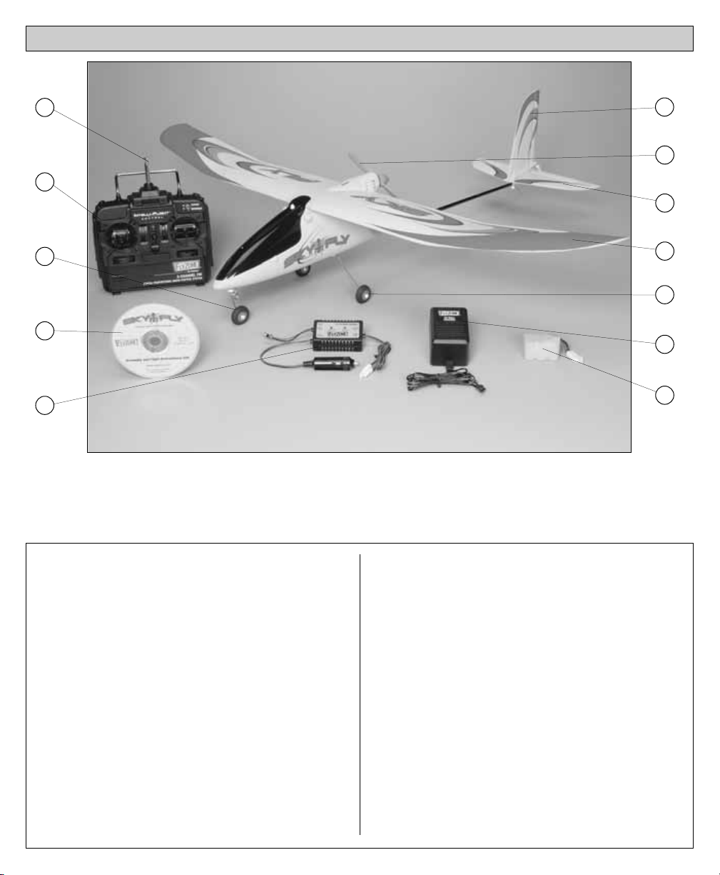
Part Name Qty.
❏ 1. Transmitter Antenna................1
❏ 2. Transmitter..............................1
❏ 3. Nose Gear..............................1
❏ 4. Instruction DVD.....................1
❏ 5. 12V DC Peak Charger............1
❏ 6. Vertical Stabilizer ...................1
❏ 7. Propeller ................................1
❏ 8. Horizontal Stabilizer ..............1
❏ 9. Main Wing.............................1
❏ 10. Landing Gear .......................1
❏ 11. AC Wall Adapter ..................1
❏ 12. 7.2V 900 mAh NiMH Battery..1
ITEMS NOT SHOWN
Part Name Qty.
❏ Wing Mounting Bands .............4
❏ Control Bands ..........................2
❏ Instruction Manual...................1
UNPACKING THE BOX
Check the parts against the list below. If any parts are damaged or
missing, give us a call at: (217) 398-8970.
Page 4
Remove the fuselage from the packaging. Be careful
when removing the fuselage from the packaging as the
control wire is preinstalled in the fuselage and
connected to the control surfaces. Lay the parts out on
a table ensuring the control wires are not intertwined or
twisted together. Remove the twist tie around the
antenna wire and let the excess wire hang freely from
the fuselage as shown in the pictures below. DO NOT
CUT OFF EXCESS ANTENNA WIRE!
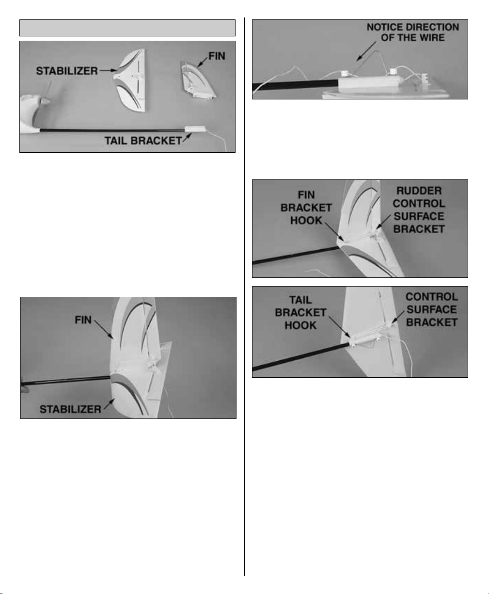
Remove the retaining nuts and tail skid wire from the bolts
of the fin. Position the stabilizer on the bracket on the tail of
the fuselage. The indentations on the underside of the
stabilizer will line up with the pegs on the tail bracket.The
control wire should be on top of the stabilizer. Make sure
the control wires are out of the way, then slide the fins
threaded posts through the stabilizer until the fin and
stabilizer are seated together as shown. Be sure that the
antenna wire that passes through the fuselage will not
become damaged by the threaded posts. If necessary,
use a toothpick or something similar to insert into the
threaded post holes and push the wire aside.
Replace the metal tail skid wire; note the direction of
the wire. Attach two nylon retaining nuts to the bolts on
the fin. Tighten these nuts down to hold the tail
assembly together. Do not over tighten as the elevator
and rudder could become damaged.
Locate the two small control surface bands. Attach one band
to the outer hook on the fin bracket and the rudder control
surface. Attach the second band to the hook on the tail
bracket and the underside of the elevator control surface.
ASSEMBLE THE TAIL
4
Page 5

Locate the main landing gear. Remove the thumb screw
and insert the landing gear into the slot on the fuselage
as shown.
Replace the thumb screw to hold the main gear in place.
Follow the same procedure to install the nose gear
as shown.
The included 12V DC Peak Charger can be plugged directly
into an automobile 12 V receptacle. The charger can also be
powered with 120V AC by using the AC wall adapter. The
AC wall adapter can be plugged into any household outlet
and when connected to the charger, it provides a
convenient way to recharge the SkyFly battery when a 12V
source is unavailable. NEVER PLUG THE BATTERY
DIRECTLY INTO THE AC WALL ADAPTER!
• To begin charging the battery pack, plug the 12v peak
charger into your automobile or 12V AC outlet (using
the AC adapter).
• Connect the pack to the white connector on the charger.
The battery can only connect to the 12v charger in one
direction, do not force it. If using the charger in an
automobile, Do not have the engine running -
Overcharging the battery may result!
• Press the start/stop button on the charger to initiate peak
charge. The red light on the charger will illuminate
indicating that charge has begun. You can press the
start/stop button at any time during peak charge to
terminate the process. The red light will go out indicating
that peak charge has been stopped.
The peak charger will automatically detect when the battery
pack is fully charged and terminate peak charge. The red light
will go out when this has occurred. Typical charge time for a
depleted pack is approximately 1 hour. The actual time the
charger takes to fully charge the SkyFly battery pack may vary.
CHARGING THE BATTERY PACK
INSTALL THE LANDING GEAR
5
Page 6

Although the 12V DC Peak Charger automatically detects
when the battery is full and terminates peak charge, the
battery pack must not be left unattended during charging.
It is normal for the battery pack and charger to become
warm during peak charge. If however the battery pack
becomes too hot to handle, immediately terminate peak
charge by pressing the start/stop button and disconnect the
pack from the charger.
A properly cared for battery will last a long time. Always
allow a hot battery pack to cool before use or recharge,
and be sure to fully discharge the battery pack before
recharging. To fully discharge the battery pack, run the
motor at high speed until the motor starts to pulse on
and off. Remove the pack from the airplane and allow it
cool if necessary.
• ALWAYS place battery and charger outside of the vehicle!
• NEVER use this charger with your vehicle engine running!
• ALWAYS completely discharge your battery before charging!
ATTENTION: The product you have
purchased is powered by a rechargeable
battery. At the end of the battery’s useful
life, under various state and local laws,
it may be illegal to dispose of this battery
into the municipal waste system.
Check with your local solid waste officials for details in
your area for recycling options or proper disposal.
WARNING: This product contains a chemical known to
the State of California to cause cancer.
Remove the canopy by turning the locking knob 90°
either direction and lifting the rear of the canopy.
Slide the battery in at a slight angle in the nose of the
plane. While pushing it forward, gently push down on
the rear of the battery to fit it in place. It will be a snug
fit but the battery should rest fully in the battery
compartment as shown. Do not connect the battery
until you are ready to fly.
On the underside of the canopy there is a retaining tab.
This will slide into the hole in the front of the fuselage.
Once the canopy is in place, secure it by rotating the
locking knob at the top of the canopy.
ATTACH THE CANOPY
CONNECT THE BATTERY
BATTERY RECYCLING
CHARGING PRECAUTIONS
IMPORTANT!
NEVER LEAVE A CHARGING
BATTERY UNATTENDED
6
Page 7

Slide the front of the wing under the canopy and position
the wing flat and centered on the fuselage. Secure the wing
with two rubber bands, straight from the front to rear pegs.
Attach two additional rubber bands diagonally over the top
of the wing. Only use four rubber bands to attach the wing
to the fuselage.
Your model comes out of the box "factory balanced." The
following information takes you through the process of
balancing the model should you need to do so.
Use a fine-point felt-tip pen to mark the balance range on both
sides of the bottom of the wing according to the
measurements shown in the photo. Note that the
measurements are from the front, or leading edge of the wing.
With the battery in place, lift the model with your
fingertips between the lines under the wing. Position
your fingertips where necessary to get the model to sit
level, or “balance”. If your fingertips are between the
lines, the SkyFly is ready to fly.
If the model balances with your fingertips ahead of the
lines, weight will have to be added to the tail to get it to
balance. Tail weight may be stuck to the bottom of the
stabilizer at the center. Be sure that any added weight
does not interfere with the operation of the elevator.
If the model balances with your fingertips behind the
lines, weight will have to be added to the nose to get the
model to balance. Nose-weight may be stuck to the
upper inside of the fuselage just in front of the hole for
the canopy retaining tab. Stick-on lead weight may be
purchased from your local hobby shop.
Stick on as much weight as required to get the model to
balance when lifted by your fingers between the lines. If
you added any weight, recheck the balance.
BALANCE THE MODEL
ATTACH THE WING
7
Page 8

The SkyFly transmitter is equipped with an
Expert/Beginner switch. When this switch is in the
"Beginner" position, the transmitter will automatically
combine or "mix" a small amount of up elevator when
rudder input is provided to help maintain altitude when
turning. In "Expert" mode, there are no flying aids or
"mixing" to help the pilot.
Locate the antenna and screw it into the top of
the transmitter.
The transmitter that controls your airplane requires power,
in the form of eight “AA” batteries. To install the batteries,
remove the battery cover on the back of the transmitter.
Pull the battery holder out of the transmitter case and
install eight new “AA” batteries, following the diagram
on the holder.
Reinsert the battery holder in the transmitter case. Reinstall
the battery cover on the back of the transmitter case.
Switch on the transmitter and check the LED on the front of
the transmitter. If the LED is green, it is safe to fly. If the LED
is flashing red and beeping repeatedly, you need to install
fresh batteries. Note: The transmitter will always beep twice
when first turned on.
Note: The SkyFly transmitter is equipped with a charge
jack that allows NiCd or NiMH batteries to be charged
without removing them from the transmitter. In order to
use the charge jack, a separate charge jack conversion
kit (HCAP6010) must be purchased. The kit comes with
(8) "AA" rechargeable NiCd batteries and a 2-3 hour
quick charger.
Be sure your transmitter has fresh “AA” batteries
installed (not included). Turn on the transmitter and
center the trims tabs. Staying clear of the propeller,
remove the canopy from the SkyFly and connect the
battery to the receiver/ESC. If necessary, adjust the
control surfaces with the adjustment knobs to center
them or use the trim levers on the radio.
Using the adjustment knobs on the elevator and rudder
control horn, adjust each control line until the control
surfaces are level with the fin and stabilizer.
If at any time the control wire needs to be rethreaded onto
the adjustment knobs, rotate the knob until the small hole
in it aligns with the outer hole in the control horn.
CHECK THE CONTROL DIRECTIONS
CAUTION
• Do not mix old and new batteries.
• Do not mix alkaline, standard (carbon-zinc) or
rechargeable (NiCd) batteries.
PREPARE THE TRANSMITTER
8
Page 9

Feed the control surface wire through the hole in the
control horn and then through the hole in the
adjustment knob. Pull approximately ¾" [19mm] of
excess wire through the knob.
While holding the excess wire taught, rotate the knob
so that the wire is reeled in. A few rotations will then
keep the wire tight on the knob. Adjust the knob until
the control surface is level.
Check the operation of all control surfaces. If the motor
begins rotating with the throttle at its lowest position,
adjust the throttle trim to stop the motor from turning.
The SkyFly should be flown only when the wind speed
is 5 mph or less. If the wind is calm or very light, the
SkyFly will be docile and easy to control. Also, find an
area clear of trees, power lines and other structures. A
flying field for R/C planes is best. Don’t fly around
groups of people, especially children or within 6-miles
of existing R/C flying fields.
Find an open area free of buildings, trees, power lines and
people. For your first few flights, fly only when the wind is
calm. After you are comfortable with the airplane, you can
fly in winds that are no more than 5 miles per hour. If flown
in stronger winds, the plane may be blown down wind and
not have enough power to get back.
Make sure the battery pack is fully charged and that the
transmitter has fresh “AA” batteries installed.
If others are flying in the same area, make sure that they
are not using the same channel radio system you are.
The front of your transmitter has a tag with a number on
it (i.e. 1 through 6 and 26.995 through 27.255). This is
the channel number and frequency you are using. If
someone is on the same channel or frequency, DO NOT
switch on your transmitter until they are finished flying.
Your transmitter controls the altitude, direction and
speed of the airplane. The right stick controls the
altitude and direction and the stick on the left side of the
transmitter controls the speed.
When the battery power gets too low, the “Auto Cut-Off”
feature of the speed control provides an extra degree of
insurance. It reacts to low power by pulsing the motor on
and off, in effect saving power for the receiver. That way your
airplane goes into a glide and you stay in control as you land.
First, extend the transmitter antenna and switch your
transmitter power switch “ON.” Be sure your throttle stick is
moved all the way to the bottom position.
Second, connect your battery to the electronic speed
control in the fuselage.
Caution: Keep your hands away from the propeller.
FLYING THE SKYFLY
PREPARE FOR TAKEOFF
CHOOSE A GOOD FLYING SITE
9
3-CHANNEL
TRANSMITTER
3-CHANNEL
TRANSMITTER
3-CHANNEL
TRANSMITTER
Page 10

The throttle stick must be first moved to the idle (bottom)
position in order to activate the throttle function. Once this
is done, the propeller is now armed. Moving the throttle
stick upward will cause the prop to rotate. The farther the
stick is moved, the faster it will spin.
Perform a range check your radio before each flight. Switch
on the airplane and then switch on the transmitter. Have a
helper hold the airplane. With the transmitter waist high and
the antenna collapsed, walk 100 feet away from the
airplane, holding the transmitter with the antenna pointing
up. Move the control stick, checking that the control
surfaces respond. Also, turn the motor on and check the
range. If you still have control of the airplane, it is safe to
extend the transmitter antenna and fly the airplane. If you
do not have control of the plane, make sure the batteries in
the transmitter are fresh and the battery in the plane is
charged. Also, make sure the wire antenna is extended out
the back of the airplane.
With the throttle stick moved fully upwards, hand launch
the SkyFly into the wind, at a slight upward angle. Note: For
the first couple of flights, we recommend having a helper
hand launch the airplane. After you become familiar with
the flight characteristics of the airplane, it can be flown off
a hard surface instead of being hand launched.
Pull the right stick toward you so that the plane climbs at a
20 to 30 degree angle. Allow the airplane to climb a few
seconds before turning it.
When your airplane is moving away from you, moving the
right stick to the left will make your plane turn to the left.
Moving the stick to the right will make the airplane turn to
the right. By adding a little up elevator (moving the right
stick towards you) during the turn, the airplane will turn
much tighter. To stop the turn, move the stick the opposite
direction until the airplane is flying straight. Caution: It only
requires a small amount of up elevator. If using the beginner
mode, this is done for you.
When the airplane is coming toward you, moving the right
stick left still causes left rudder, but your airplane goes to
your right. In short, you have to reverse the way you control
the rudder. Here’s a good way to familiarize yourself with
the controls: When the airplane is coming toward you, turn
your body so that you are facing the same direction the
airplane is going, looking over your shoulder at the airplane.
Now when you move the rudder stick left, the plane will go
to your left.
Now that you have gained some altitude, it is time to trim the
plane for straight, level flight. If the airplane wants to climb
when the elevator stick is released, move the elevator trim
lever up. If the airplane wants to dive, move the elevator trim
lever down. It should require very little trim. Your goal is to
have the airplane fly level with the elevator stick centered.
Now, with the airplane flying level, check to see if the
airplane is flying straight. If it wants to turn when the rudder
stick is centered, move the rudder trim lever opposite the
direction the airplane is turning. The airplane should be
trimmed so that if you take your hands off of the control
stick, the airplane will fly straight and level on its own.
Having the airplane trimmed properly makes flying much
easier and more enjoyable.
Don’t let the airplane get too far away from you. The farther
away it is, the harder it is to see what the airplane is doing.
When learning to fly, it is best to keep the airplane high
enough so that if you make a mistake, you have enough
altitude to correct the mistake.
It’s a known fact among fellow R/C pilots that your
airplane will land. It is up to you as to where and how
it lands. For your first couple of flights we recommend
that you attempt to land before the motor stops. Your
SkyFly comes with an auto cut-off feature which
reserves battery power for safe landings. During your first
flight, while at a high altitude, turn the motor off and notice
how the SkyFly reacts. This will give you an idea of how the
airplane will react during a landing.
To land the SkyFly, fly down wind, past the landing area.
Gently turn into the wind and reduce the throttle so that the
airplane starts to come down. Adjust the throttle as needed
to reach the landing area, but not fly past it.
Just before landing, at about 1 foot above the ground,
apply a little up elevator to flare (raise the nose of the
airplane). This will cause the airplane to slow and settle
to the ground.
Caution: If, during a rough landing, the propeller on
the SkyFly should become jammed and cannot rotate
with the throttle in the run position, the battery and
speed control will become very hot. Immediately
move the throttle stick down to stop the motor. If you
fail to do this, the motor, speed control and/or battery
will be damaged.
IT'S NOW TIME TO LAND
10
Page 11

Unplug the battery from the airplane and switch the
transmitter off. Remove the battery from the battery
compartment. Allow the motor and battery to cool before
recharging. Check the airplane over to make sure nothing
has come loose or may be damaged.
Always follow this sequence before and after each flight.
TO FLY:
1. Move throttle stick to the "motor off" position (off).
2. Turn on transmitter and extend antenna.
3. Plug in airplane battery (motor is now armed).
AFTER FLIGHT:
1. Move throttle stick to the "motor off" position (down).
2. Unplug battery from the airplane.
3. Turn off transmitter.
To order replacement parts for your SkyFly, use the order
numbers in the parts list. Replacement parts are available
only as listed. Replacement parts are not available from
Product Support, but can be purchased from hobby shops
or mail order/internet order firms. If you need assistance
locating a dealer to purchase parts, contact:
Product Support
Phone: 217-398-0007
Fax: 217-398-7721
E-mail: productsupport@hobbico.com
Before starting to build, take an inventory of this kit to make
sure it is complete and inspect the parts to make sure they
are of acceptable quality. If you need assistance with
assembly, contact Product Support. When reporting
defective or missing parts, please use the part names exactly
as they are written in the parts list.
Even the best R/C pilots in the world damage their airplanes
every now and then. In the unfortunate event that you
damage your airplane, repairs are fairly simple to make
yourself. If there are any cracks in the wing or fuselage,
apply 6-minute epoxy or white glue to the broken areas and
hold together with clear packaging tape. Let the glue cure,
leaving the tape in place for added strength.
Stock # Description
HCAP9925..........CHARGER 12V DC PEAK w/blk plug
HCAP9951 ..........CHARGER 12V DC PEAK w/red 2 pin
HCAP9926..........AC WALL ADAPTER w/blk plug
HCAP9950..........AC WALL ADAPTER w/red 2 pin
HCAA3850 .........BATTERY 7.2V 900MAH NIMH
HCAA3851 .........MAIN WING
HCAA3852 .........VERTICAL STABILIZER W/ACCY
HCAA3853 .........HORIZONTAL STABILIZER W/ACCY
HCAQ3490.........PROPELLER
HCAA3854 .........CONTROL LINKAGE
HCAG1055 .........MOTOR 380
HCAG056 ...........MOTOR MOUNT PLATE W/SCREWS
HCAM7525 ........RECEIVER UNIT
HCAL7550..........CRYSTAL SET 26.995
HCAL7551..........CRYSTAL SET 27.045
HCAL7552..........CRYSTAL SET 27.095
HCAL7553..........CRYSTAL SET 27.145
HCAL7554..........CRYSTAL SET 27.195
HCAL7555..........CRYSTAL SET 27.255
HCAL7575..........TRANSMITTER
HCAA3861 .........MAIN LANDING GEAR
HCAA3862 .........FRONT LANDING GEAR
HCAA3863 .........SCREW LANDING GEAR (2)
HCAA3864 .........WING MOUNTING BAND (4)
HCAA3865 .........TAIL CONTROL BAND (2)
HCAA3867 .........TAIL BRACE
HCAA3868 .........CONTROL HORN/KEEPER (2)
HCAA3870 .........CANOPY COVER
HCAM7526 ........ANTENNA TX (2)
HCAA3873 .........HOLD DOWN ROD/CAPS (4)
HCAM7527 ........BATTERY COVER TX
HCAA3869 .........FUSELAGE W/ BOOM
HCAA3871 .........TAIL SKID WIRE
HCAA3872 .........VERTICAL STAB NUTS (2)
PARTS LIST
REPAIRS
REPLACEMENT PARTS
SAFETY CHECKLIST
AFTER THE FLIGHT
11
Page 12

Reef Racer 2™Ready-to-Run Electric Boat
HCAB14**
The 15" long Reef Racer 2 comes with radio gear,
380-size motor and ESC installed...and a 6-cell NiMH
battery and 12V DC charger included. Drop in the
charged battery pack, bury the throttle and it leaps into
action! You'll enjoy quick response and "turn on a dime"
maneuverability - even at top speed. If you happen to
flip or roll - don't worry! The self-righting hull gets you
back into action in seconds. And if you're a southpaw,
you can quickly adapt the included AquaCraft pistol for
left-hand use with just a Phillips screwdriver. Available
in six sizzling colors. Requires only 8 "AA" batteries.
NexSTAR™Ready-to-Fly R/C Trainer
HCAA17**
No other trainer offers so much for the first-time pilot: a
Futaba
®
radio, an O.S.®engine, and a special NexSTAR
edition of the Great Planes
®
RealFlight™R/C Simulator!
The 4YBF 4-channel is factory-installed and features
AFS™ (Active Flight Stabilization), which automatically
detects and corrects any signs of uneven flight. The .46
FXi™ engine starts easily and effortlessly every time,
and requires no adjustments. And RealFlight lets you
practice flying the NexSTAR anytime, using your Futaba
transmitter as the controller, right on your PC. You'll
develop confidence in piloting all of the plane's special
features before you even take your 69" span NexSTAR
to the flying field for the first time!
Sea Scout™Ready-to-Run Micro R/C Sub
HCAB0020
The nearly 5" long Sea Scout with working lights takes
R/C "undersea" - so easily that even 8-year-olds can be
the commander. Two motors turn propellers for steering
and forward/reverse thrust. A third motor offers instant
diving or surfacing ability (even straight up and down!).
The Sea Scout's built-in NiMH battery recharges in just
minutes on the provided DC battery charger. A
3-channel transmitter is also included. Available on
27MHz (Black, HCAB0020) or 49MHz (Gray,
HCAB0021) - requires only one 9V and 6 "C" batteries.
1/10 Scale Ready-to-Run R/C Electric Stadium Truck
DTXD20**
Check it out, and you'll agree: Nothing can touch the 1/10
scale Evader ST RTR electric stadium truck for convenience,
set-up ease, performance extras or toughness. It comes
assembled, painted, and equipped for fast, easy
racing…with a 20-turn Photon Speed
™
motor, reversible
Sprint
™
electronic speed control with brake, and a DuraTrax
2-channel radio system made by Futaba
®
. All you add are a
6-7 cell NiCd battery and charger! See www.duratrax.com
for more information.
 Loading...