

Page 1
™
®
INSTRUCTION
MANUAL
Cessna 350, Corvalis, emblems, logos, and body
designs are trademarks of Textron Innovations Inc.
and are used under license by Hobbico®, Inc.
WARRANTY
Hobbico guarantees this kit to be free from defects in both
material and workmanship at the date of purchase. This warranty
does not cover any component parts damaged by use or
modification. In no case shall Hobbico’s liability exceed the
original cost of the purchased kit. Further, Hobbico reserves
the right to change or modify this warranty without notice.
In that Hobbico has no control over the final assembly or material
used for final assembly, no liability shall be assumed nor
accepted for any damage resulting from the use by the user of
the final user-assembled product. By the act of using the
user-assembled product, the user accepts all resulting liability.
If the buyer is not prepared to accept the liability associated
with the use of this product, the buyer is advised to return
SPECIFICATIONS
Wingspan:
Wing
Area:
Weight:
this kit immediately in new and unused condition to the
place of purchase.
To make a warranty claim send the defective part or item to
Hobby Services at the address below:
Include a letter stating your name, return shipping address, as
much contact information as possible (daytime telephone
number, fax number, e-mail address), a detailed description of
the problem and a photocopy of the purchase receipt. Upon
receipt of the package the problem will be evaluated as quickly
as possible.
57 in
[1450mm]
2
362 in
[23.3 dm2]
2.25 lbs
[1020 g]
Hobby Services
3002 N. Apollo Dr. Suite 1
Champaign IL 61822 USA
Wing
Loading:
Length:
14 oz/ft
2
[43 g/dm2]
38 in
[965mm]
READ THROUGH THIS MANUAL BEFORE STARTING CONSTRUCTION. IT CONTAINS IMPORTANT
INSTRUCTIONS AND WARNINGS CONCERNING THE ASSEMBLY AND USE OF THIS MODEL.
© 2011 Hobbico®, Inc. HCAA2533 Mnl
Page 2
TABLE OF CONTENTS
AMA
INTRODUCTION . . . . . . . . . . . . . . . . . . . . . . . . . . . . . . . .2
SAFETY PRECAUTIONS . . . . . . . . . . . . . . . . . . . . . . . . .2
ADDITIONAL ITEMS REQUIRED . . . . . . . . . . . . . . . . . . .3
ORDERING REPLACEMENT PARTS. . . . . . . . . . . . . . . .3
KIT INSPECTION. . . . . . . . . . . . . . . . . . . . . . . . . . . . . . . .3
KIT CONTENTS. . . . . . . . . . . . . . . . . . . . . . . . . . . . . . . . .3
BEFORE YOU BEGIN . . . . . . . . . . . . . . . . . . . . . . . . . . . .4
ASSEMBLE THE MODEL . . . . . . . . . . . . . . . . . . . . . . . . .4
PREPARE FOR FLIGHT . . . . . . . . . . . . . . . . . . . . . . . . . .7
Check the Control Directions . . . . . . . . . . . . . . . . . . . .8
Dual Rates . . . . . . . . . . . . . . . . . . . . . . . . . . . . . . . . . .9
Operate the Motor . . . . . . . . . . . . . . . . . . . . . . . . . . . .9
Check the C.G. (Center of Gravity) . . . . . . . . . . . . . . .9
Identify Your Model. . . . . . . . . . . . . . . . . . . . . . . . . . .10
FLYING THE CESSNA 350 CORVALIS. . . . . . . . . . . . . .10
Find a Suitable Flying Site . . . . . . . . . . . . . . . . . . . . .10
Perform a Range Check. . . . . . . . . . . . . . . . . . . . . . .10
Monitor Your Flight Time. . . . . . . . . . . . . . . . . . . . . . .10
Take Off . . . . . . . . . . . . . . . . . . . . . . . . . . . . . . . . . . .11
Flying . . . . . . . . . . . . . . . . . . . . . . . . . . . . . . . . . . . . .11
Landing . . . . . . . . . . . . . . . . . . . . . . . . . . . . . . . . . . . 11
Flaps . . . . . . . . . . . . . . . . . . . . . . . . . . . . . . . . . . . . . 11
After Flight . . . . . . . . . . . . . . . . . . . . . . . . . . . . . . . . .11
TTX600 INSTRUCTIONS. . . . . . . . . . . . . . . . . . . . . . . . .12
If you are not already a member of the AMA, please join!
The AMA is the governing body of model aviation and
membership provides liability insurance coverage, protects
modelers’ rights and interests and is required to fl y at most
R/C sites.
ACADEMY OF MODEL AERONAUTICS
5151 East Memorial Drive
Muncie, IN 47302-9252
Tele. (800) 435-9262
Fax (765) 741-0057
Or via the Internet at:
http://www.modelaircraft.org
IMPORTANT!!!
Two of the most important things you can do to preserve the
radio controlled aircraft hobby are to avoid fl ying near fullscale aircraft and avoid fl ying near or over groups of people.
PROTECT YOUR MODEL, YOURSELF
& OTHERS… FOLLOW THESE
IMPORTANT SAFETY PRECAUTIONS
INTRODUCTION
Thank you for purchasing the Cessna 350 Corvalis. Originally
produced by Columbia aircraft and called the Columbia 350,
the design was recently purchased by Cessna and was
renamed the Cessna 350 Corvalis–after the name of the
town near where it was being manufactured. After opening
the box, you will no doubt be anxious to see the sleek lines
of this modern single-engine aircraft come together on your
work bench. Fortunately, all of the time-consuming work has
already been done for you. Innovative assembly methods
allow this plane to virtually fi nish itself in under an hour.
Once at the fi eld, you will fi nd that the Cessna fl ies smoothly
but with authority from the pre-installed brushless outrunner
motor and LiPo battery.
For the latest technical updates or manual corrections
to the Cessna 350 Corvalis, visit the Flyzone web site at
www.fl yzoneplanes.com. Open the “manuals” link, then
select the Cessna 350 Corvalis.
1. Your Cessna 350 Corvalis should not be considered a toy,
but rather a sophisticated, working model that functions very
much like a full-size airplane. Because of its performance
capabilities, the Cessna, if not assembled and operated
correctly, could possibly cause injury to yourself or spectators
and damage to property.
2. You must assemble the model according to the instructions.
Do not alter or modify the model, as doing so may result in
an unsafe or unfl yable model. In a few cases the instructions
may differ slightly from the photos. In those instances the
written instructions should be considered as correct.
3. If you are not an experienced pilot or have not fl own
this type of model before, we recommend that you get
the assistance of an experienced pilot in your R/C club for
your fi rst fl ights. If you’re not a member of a club, your local
hobby shop has information about clubs in your area whose
membership includes experienced pilots.
4. While this kit has been fl ight tested to exceed normal use,
if the plane will be used for extremely high stress fl ying, such
as racing, or if an engine larger than one in the recommended
range is used, the modeler is responsible for taking steps to
reinforce the high stress points and/or substituting hardware
more suitable for the increased stress.
We, as the kit manufacturer, provide you with a top quality,
thoroughly tested kit and instructions, but ultimately the
quality and fl yability of your fi nished model depends
on how you build it; therefore, we cannot in any way
guarantee the performance of your completed model,
and no representations are expressed or implied as to the
performance or safety of your completed model.
2
Page 3
ADDITIONAL ITEMS REQUIRED
9
8
The following items are required for assembling the Cessna
350 Corvalis RTF:
Fine-point felt-tip pen
❏
Masking tape
❏
#2 Phillips screw driver
❏
ORDERING REPLACEMENT PARTS
Replacement parts for the Hobbico Flyzone Cessna 350
Corvalis are available using the order numbers in the
Replacement Parts List that follows. The fastest, most
economical service can be provided by your hobby dealer or
mail-order company.
To locate a hobby dealer, visit the Hobbico web site at
hobbico.com. Choose “Where to Buy” at the bottom of the
menu on the left side of the page. Follow the instructions
provided on the page to locate a U.S., Canadian or
International dealer.
Parts may also be ordered directly from Hobby Services
by calling (217) 398-0007, or fax at (217) 398-7721, but full
retail prices and shipping and handling charges will apply.
Illinois and Nevada residents will also be charged sales tax.
If ordering via fax, include a Visa® or MasterCard® number
and expiration date for payment.
Mail parts orders and payments by personal check to:
Hobby Services
3002 N. Apollo Drive, Suite 1
Champaign, IL 61822
Be certain to specify the order number exactly as listed in
the Replacement Parts List. Payment by credit card or
personal check only; no C.O.D.
If additional assistance is required for any reason, contact
Product Support by telephone at (217) 398-8970, or by
e-mail at productsupport@hobbico.com.
REPLACEMENT PARTS LIST
Order No. Description
HCAA6355
HCAA6356
HCAA6357
HCAA6358
HCAA6359
HCAA6360
HCAA6361
HCAA6362
HCAA6363
HCAA6364
HCAA6365
HCAA6366
HCAA3840
GPMM3318
TACJ2600
TACL0624
Fuselage
Wing Set
Stabilizer/Elevator
Hatch
Main Gear with Cover
Wheels/Pants
Nose Gear
30A ESC
Motor/Mount
Spinner
Light Set
9x5 Propeller
1800 mAh 15C LiPo Battery
Smart Charger
TTX600 2.4GHz Radio
TR624 Receiver
NOTE
Full-size plans
are not available.
You can download
a copy of this
manual at
hobbico.com.
KIT INSPECTION
Before starting to build, inspect the parts to make sure
they are of acceptable quality. If any parts are missing or
are not of acceptable quality, or if you need assistance
with assembly, contact Product Support. When reporting
defective or missing parts, use the part names exactly as
they are written in the Kit Contents list.
Hobbico Product Support
3002 N. Apollo Drive, Suite 1
Champaign, IL 61822
Telephone: (217) 398-8970, ext. 5 Fax: (217) 398-7721
E-mail: airsupport@hobbico.com
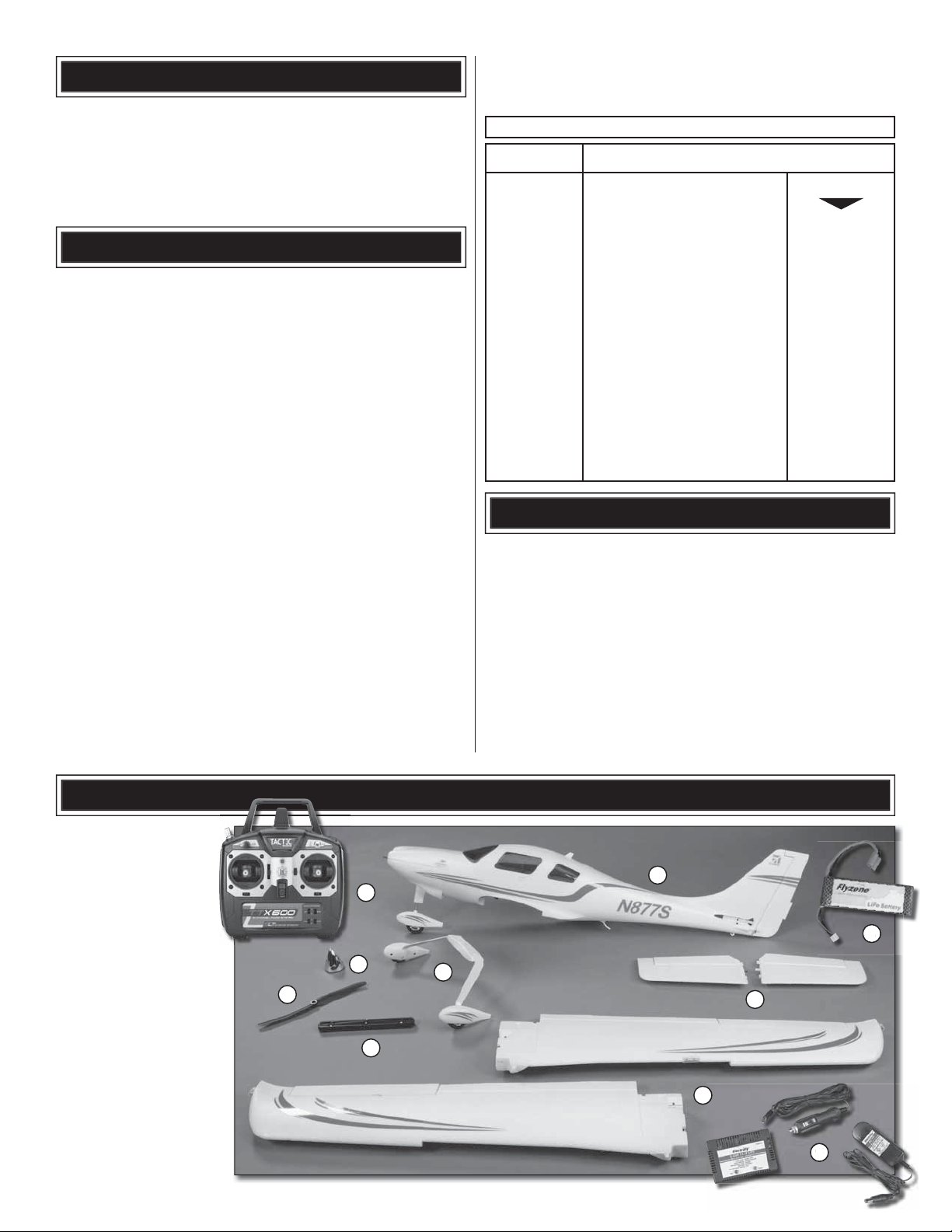
KIT CONTENTS
1. Fuselage (with nose
gear installed)
2. Wing halves (with
ailerons/flaps
installed)
3. Horizontal stabilizer
halves (with
elevators installed)
4. Main landing gear
(with wheels/
wheelpants
installed)
5. Wing joiner
6. Propeller
7. Spinner
8. Battery
9. Charger
10. Transmitter
1
10
8
7
6
5
4
3
2
9
3
Page 4
BEFORE YOU BEGIN
Before you begin assembling your Cessna 350 Corvalis,
thoroughly read the instruction manual included with the
battery charger. Also familiarize yourself with the following
lithium polymer battery cautions. When satisfi ed with your
understanding of the battery charge process and safe
handling of LiPo batteries, charge your fl ight battery so it will
be ready to use when your assembly is complete.
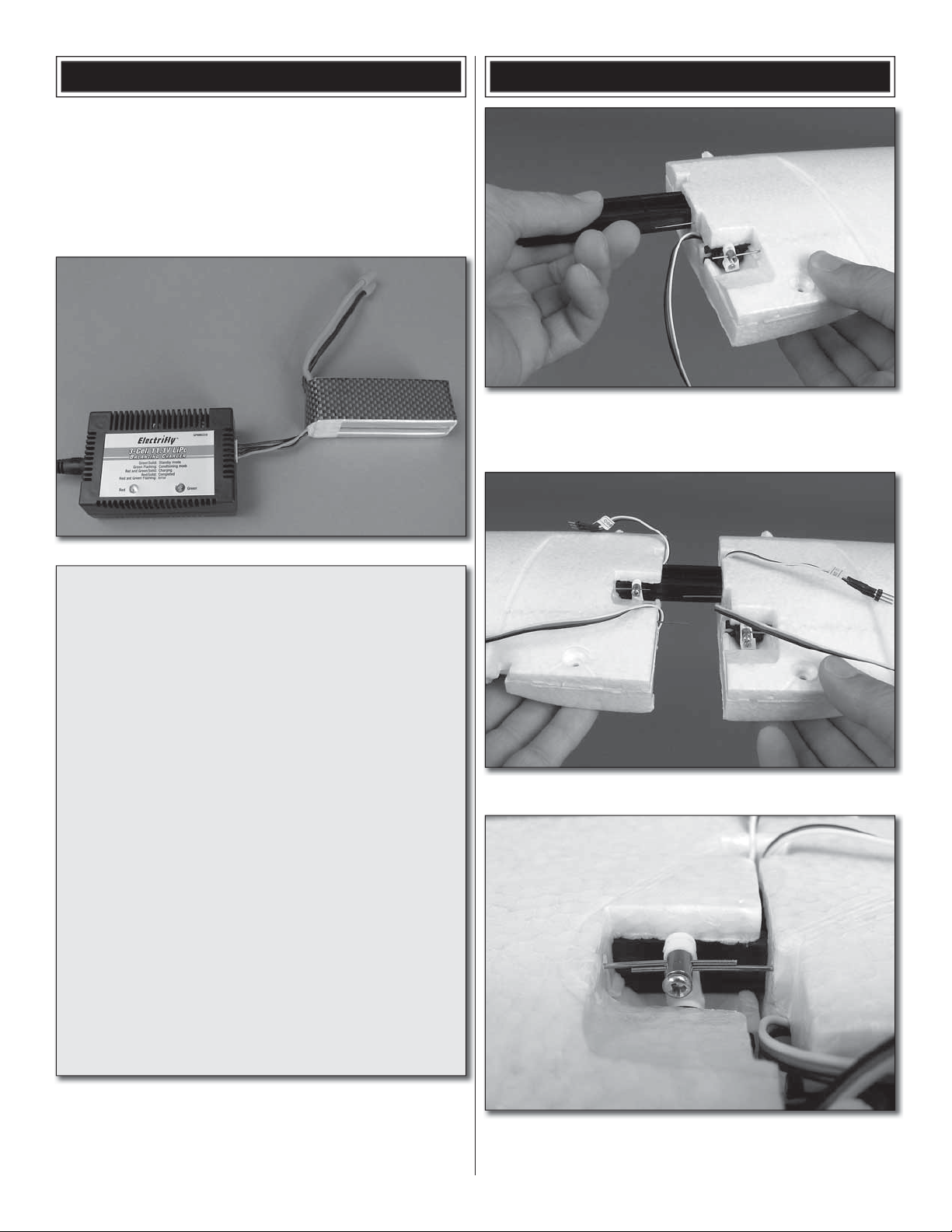
ASSEMBLE THE MODEL
1. Insert the wing joiner into the wing pocket of one wing
❏
panel. Be sure that the “V” shape of the joiner points toward
the underside of the wing.
LITHIUM BATTERY HANDLING AND USAGE
WARNING!! Read the entire instruction sheet included
with your battery charger. Failure to follow all instructions
could cause permanent damage to the battery and its
surroundings, and cause bodily harm!
• ONLY use a Li-Po approved charger. NEVER use a
NiCd/NiMH peak charger!
• NEVER charge in excess of 4.20V per cell.
• ONLY charge through the “charge” lead. NEVER charge
through the “discharge” lead.
• NEVER charge at currents greater than 1C.
• ALWAYS set charger’s output volts to match battery volts.
• ALWAYS charge in a fi reproof location.
• NEVER trickle charge.
• NEVER allow the battery temperature to exceed 150° F
(65° C).
• NEVER disassemble or modify pack wiring in any way
or puncture cells.
• NEVER discharge below 3.0V per cell.
• NEVER place on combustible materials or leave
unattended during charge or discharge.
• ALWAYS KEEP OUT OF REACH OF CHILDREN.
2. Fit the other wing panel onto the wing joiner.
❏
3. The aileron and fl ap pushrod wires must pass through
❏
the holes in the screw lock connectors when the wing panels
are joined together.
4
Page 5
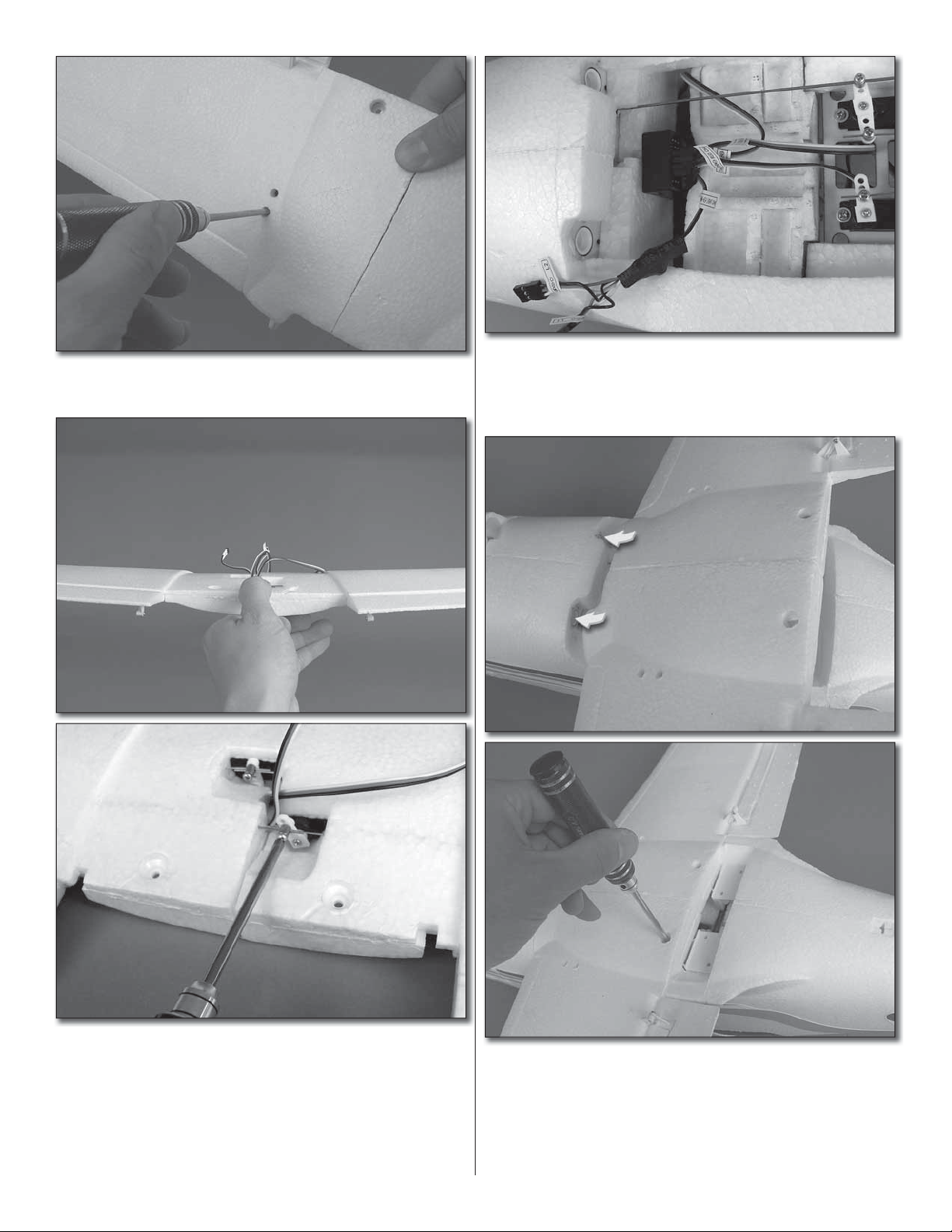
4. Tighten the wing joiner screws that can be seen through
❏
the access holes in the underside of the wing panels.
6. Connect the aileron servo lead to channel 1 on the
❏
receiver and the fl ap servo lead to channel 6 on the receiver.
Connect the wing lights to the Y-harness (which is already
plugged into channel 5).
5. Position the fl aps and ailerons inline with each other
❏
(left aileron and right aileron even with each other, left fl ap
and right fl ap even with each other) and tighten the screws in
the screw lock connectors. Note: After the receiver has been
installed and you test the operation of the fl aps and ailerons,
you may need to loosen the screws, reposition the pushrod
wires in the screw lock connectors, and retighten the screws.
7. Insert the wing dowels into the holes in the fuselage
❏
at the front of the wing saddle. Make sure that none of the
servo wires interfere with the tail servos. Press the wing
into place and attach it to the fuselage using two 3x22mm
machine screws.
5
Page 6
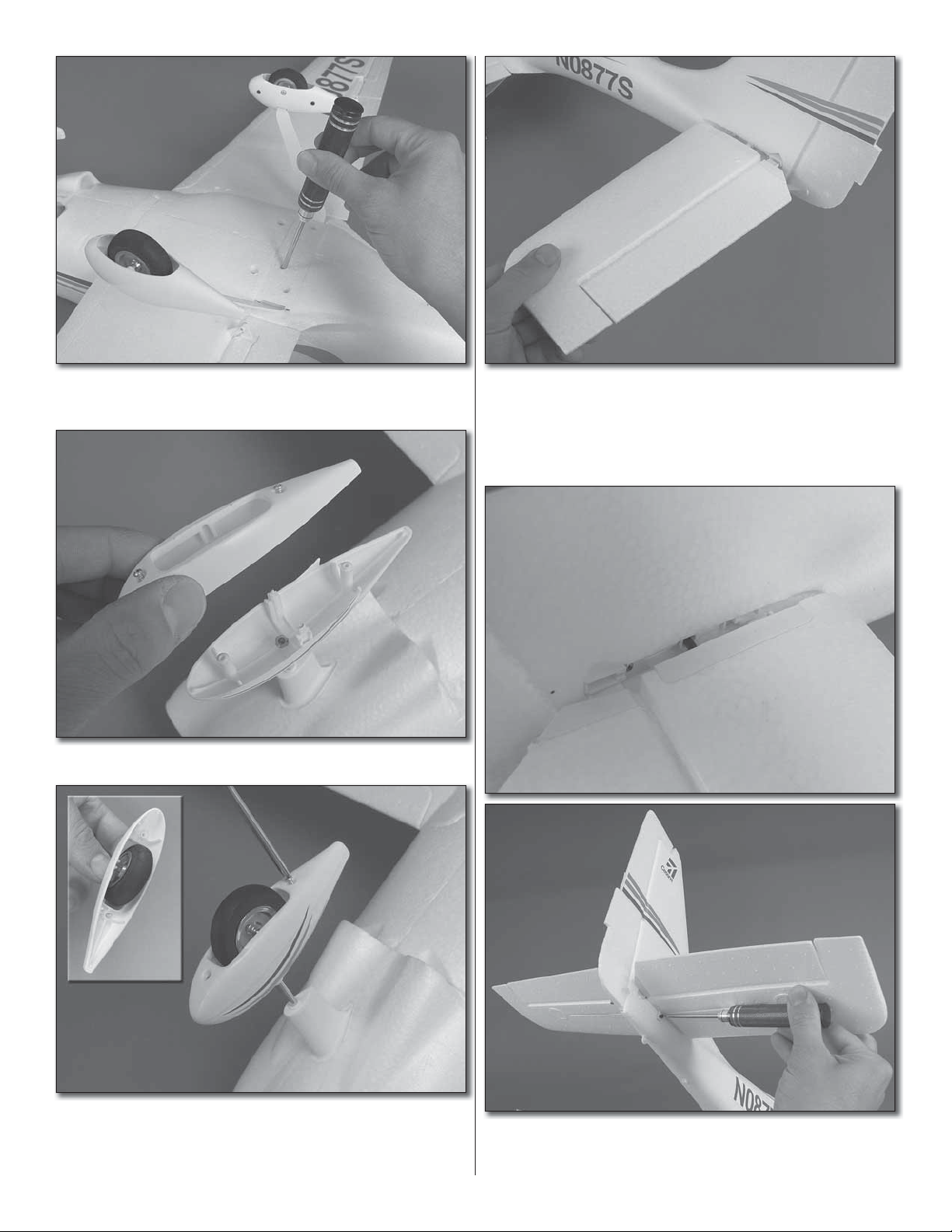
8. Mount the landing gear to the fuselage using four
❏
3x16mm self-tapping screws.
9. Unscrew the bottom half of the nose wheel pant.
❏
11. Slide the left horizontal stabilizer onto the fuselage.
❏
Align the plastic fi ttings into their mating slots in the fuselage
and press the stab half against the fuse until fully seated.
10. Insert the nose wheel axle through the nose wheel and
❏
fi t it into the grooves in the lower nose wheel pant. Replace
the lower nose wheel pant and screw it back into place.
12. Install the right horizontal stabilizer in the same
❏
manner. Thread a 2.5x8mm self-tapping screw into each
stab mounting hole and tighten them securely.
6
Page 7

PREPARE FOR FLIGHT
1. Remove the cowl top by grasping it through one of the
❏
front cooling holes and lifting up.
13. Remove the spinner cone by unscrewing the two
❏
screws that hold it to the spinner backplate. Install the
propeller followed by the prop washer and then the prop nut.
Thoroughly tighten the prop nut. Reinstall the spinner cone.
14. Install the antenna onto the underside of the fuselage.
❏
Apply a couple drops of glue to the base of the antenna
before fi tting it in place. CA, epoxy, white glue, hot glue, or
any other household glue would be acceptable.
2. With your battery fully charged, slide it into the battery
❏
compartment as far as it will go. Secure the battery with the
hook and loop strap attached to the battery compartment.
Do not yet plug the battery into the ESC!
7
Page 8

3. Turn on your transmitter. Move the throttle stick to the
❏
middle position (50% of stick travel). Each and every time
before you plug your fl ight battery into the ESC you must be
sure that the propeller is free of anything that could interfere
with its rotation and is pointed in a safe direction.
4. Being careful to keep your hands clear of the propeller
❏
arc, plug the battery into the ESC. Reinstall the cowl top onto
the fuselage and confi rm that it is securely clipped into place.
2. Move the elevator stick down. The elevators should
❏
move up. If they do not, change the position of the elevator
channel servo reversing switch.
Check the Control Directions
As described in the previous section, your throttle stick
should still be in the middle position. When checking the
control directions, keep the throttle stick in this position
to avoid arming the ESC until you are ready to operate
the motor. (If the control surfaces do not operate with the
transmitter, follow the binding procedure found on page 14.)
1. Viewing the model from behind, move the rudder stick
❏
to the right. The rudder should move to the right as shown. If
it does not, change the position of the rudder channel servo
reversing switch.
3. Move the aileron stick to the left. The left aileron
❏
should move up and the right aileron move down. If they do
not, change the position of the aileron channel servo
reversing switch.
4. Rotate the fl ap dial on the transmitter and test the
❏
operation of the fl aps.
5. With the trim levers all in the neutral position, confi rm
❏
that the control surfaces are still centered. If necessary,
remove the wing from the fuselage and make adjustments
to the positions of the pushrods in the screw lock connectors
to re-center the control surfaces. Double check that the left
fl ap and aileron are inline with the right fl ap and aileron.
8
Page 9

Dual Rates
Check the C.G. (Center of Gravity)
The dual rate switch (D/R)
on the transmitter changes
the amount of control throw
from high rate (advanced
aerobatic fl ying) to low rate
which is for more gentle
control and also is good for
pilots with less experience.
It is suggested that at least
the fi rst fl ight be done on
the low rate setting until you
become familiar with the
fl ight characteristics of the
Cessna 350 Corvalis.
Operate the Motor
1. Move the throttle stick to the middle position and plug
❏
the battery into the ESC. Move the throttle stick to the idle
position. The ESC will make an audible tone (either one tone
or two tones). Assume now that the ESC is armed and the
propeller will rotate when the throttle stick is advanced!
The C.G. (Center of Gravity) is the location on the wings,
measured back from the leading edge on both sides of
the fuselage, where the model balances. In addition to the
control surface throws, the C.G. has a GREAT effect on the
way the model fl ies. If the C.G. is too far aft (tail heavy), the
model will be too responsive and diffi cult to control. If the
C.G. is too far forward (nose-heavy), the model will be too
stable and not responsive enough. Follow the instructions
to make sure the model is balanced properly and the C.G.
is in the correct location.
2. With a fi rm grip on the tail of the plane and the propeller
❏
pointed in a safe direction, slowly advance the throttle stick.
The propeller should begin to rotate. If it does not, return the
throttle stick to the idle position, disconnect the battery, and
fl ip the throttle channel servo reversing switch.
3. Move the throttle stick to the middle position. Reconnect
❏
the battery. Move the throttle stick to the idle position. With a
fi rm grip on the tail of the plane, slowly advance the throttle
stick and confi rm that the propeller rotates.
4. The ESC is equipped with a BRAKE feature. We
❏
recommend fl ying the Cessna with the brake OFF. When
the ESC is armed, one beep indicates the brake is off. Two
beeps indicate the brake is on. To toggle the brake on and
off, fi rst disconnect the battery from the ESC. Advance the
throttle stick to full throttle and reconnect the battery. After
a few moments, the motor will emit a tone (one beep for
brake off, one beep for brake on). Move the throttle to the
idle position to arm the ESC. If you wish to toggle the brake
feature on or off again in the future, repeat this step.
Note: The motor is connected to the ESC at the factory to
rotate in the correct direction. If at any time you disconnect
the motor from the ESC for repair or replacement and the
motor rotates the wrong direction, simply disconnect any
two of the three motor leads and swap their positions.
5. Disconnect the battery from the ESC but leave the
❏
battery installed in the fuselage to check the C.G.
1. Place pieces of masking tape onto the top of each wing
❏
panel. Measure back from the leading edge of the wings
where they meet the fuselage and draw three lines onto
each piece of tape using the measurements shown. These
three lines represent the forward limit, recommended and aft
limit C.G. positions.
2. With the battery and cowl top installed, place your
❏
fi ngers on the middle balance marks, turn the plane upside
down and lift the model. The fuselage should remain level—
it may be helpful to have an assistant view the model from
the side (or have your assistant lift the model) to see if it
is level. If the nose of the plane drops, move your fi ngers
forward of the middle lines and recheck the balance. If the
tail of the plane drops, move your fi ngers aft of the middle
lines and recheck the balance. As long as the plane will
9
Page 10

balance with your fi ngers somewhere between the forward
and aft lines, the Cessna will be safe to fl y. We recommend
that the plane balance at or close to the middle lines, at least
for your fi rst few fl ights. Add weight to the nose or tail of
the plane as necessary until the plane balances with your
fi ngers on the middle lines. If the tail drops, nose weight
will be required. If the nose drops, then tail weight will be
required. The best way to add weight to balance the model
is to place segments of stick-on lead weight on the fuselage
wherever it may be needed. For this, Great Planes stick-on
lead weight (GPMQ4485) should be used.
made on the top of the wing. Moving the C.G. forward (nose
heavy) will improve the model’s stability. This could be an
advantage on breezy days. Moving the C.G. aft (tail heavy)
will make the model more sensitive to control input.
Identify Your Model
No matter if you fl y at an AMA sanctioned R/C club site or
if you fl y somewhere on your own, you should always have
your name, address, telephone number and AMA number on
or inside your model. It is required at all AMA R/C club fl ying
sites and AMA sanctioned fl ying events and simply a “good
idea” even if fl ying somewhere else. Write this information on
a strip of masking tape and place it on the inside of the cowl
top (or simply write the information directly on the inside of
the cowl top).
FLYING THE CESSNA 350 CORVALIS
Although the Cessna 350 Corvalis is an extremely sturdy
airplane made of durable foam, its low wing confi guration
does not have the self-righting characteristics of a trainer
plane and is therefore not recommended for beginner pilots.
The Cessna is, however, easy to fl y even for pilots with
moderate experience. If you have not previously fl own a
trainer it is strongly suggested that you learn to fl y with one
fi rst. Or, get the assistance of an experienced pilot to help you
with the fi rst few fl ights (or however many it takes until you are
profi cient with the entire fl ight from take-off to landing).
3. Determine the amount of weight required by placing
❏
segments over the cowl or tail where shown, but do not
attach the lead yet.
4. Once you can get the model to balance and you know
❏
how much lead will be required, permanently stick it into
position. If nose weight is required, you could simply stick it
to the bottom of the fuselage just in front of the nose landing
gear. If you prefer the lead to be concealed, stick it out of
the way in the battery compartment. If tail weight is required,
simply adhere it to the underside of the horizontal stabilizer.
5. Recheck the C.G. to make certain the model still
❏
balances where required. Once fi nished, remove the battery.
Never charge the battery while it is installed in the model.
6. Later, once you become an expert at fl ying your Cessna,
❏
you may change the fl ying characteristics by changing the
balance point—but do not go beyond the marks you already
Find a Suitable Flying Site
Find a fl ying site clear of buildings, trees, power lines and
other obstructions. Until you know how much area will be
required and have mastered fl ying your Cessna in confi ned
spaces, a site at least the size of two or three football fi elds
should be adequate—a fl ying fi eld specifi cally intended for
R/C planes is best. Don’t fl y within six miles of R/C fl ying
fi elds and never fl y near people—especially children who
can wander unpredictably.
Perform a Range Check
The “range” is the safe operating distance from the Tx to
the Rx, and should be as far as you can clearly see the
model. With the assistance of another person, place the
aircraft on the ground and walk 100 feet (30m) away from
the model. With the Tx pointed directly at the model, operate
the transmitter’s controls, and ensure the movement of all
surfaces is according to the movement of the transmitter.
Monitor Your Flight Time
Monitor and limit your fl ight time using a timer such as the
one on your wrist watch. When the batteries are getting low
you will usually notice a performance drop before the ESC
cuts off motor power, so when you notice the plane fl ying
slower you should land.
10
Page 11

To avoid an unexpected dead-stick landing on your fi rst fl ight,
set your alarm or timer to a conservative 4 minutes. When
the alarm sounds you can either land your model or, if you
are an experienced pilot, you may continue to fl y–planning
for a dead-stick landing to see just how long the motor will
run. Circle the plane upwind of the landing area until the
motor quits. Note the run time, then land.
When you learn how much fl ight time you are getting you
can adjust your timer accordingly. Always be conservative so
the motor won’t quit unexpectedly and you will have enough
battery to land under power.
Takeoff
Until you have become comfortable with fl ying your
Cessna 350 Corvalis, do not fl y if the wind speed is
greater than 10 mph [16 km/hr].
One fi nal check before takeoff: always double-check
the fl ight control response to your inputs from the
transmitter before every fl ight. Be certain the ailerons,
elevator and rudder respond correctly and that none of the
controls have inadvertently become reversed.
Place the model on your “runway” with the nose pointing into
the wind—this will reduce the ground speed that must be
reached and automatically provide “heading assist,” making
steering and takeoff easier. Slowly advance the throttle,
adding rudder correction as needed to keep the model rolling
straight. When the plane becomes “light” continue to apply
throttle until you are at full-power—all this will happen in a
few seconds. When suffi cient liftoff speed has been reached
gradually apply “up” elevator, allowing the model to leave the
ground. Do not “yank” up on the stick—rather, be smooth
and allow the plane to establish a gentle climb.
Once you have reached a safe fl ying speed at a comfortable
altitude (approximately 50’ [15m]), work the controls as
necessary to establish a gentle turn away from the runway.
the plane will fl y straight without any control inputs. Often,
your assistant can reach over and adjust the trims for you.
Remember to keep the model high enough to give yourself
time to make corrections, but don’t let it get too far away.
Otherwise, it will be diffi cult to see its attitude and which
way it is going. Also, be sure to attempt your fi rst roll with
adequate altitude. The long wingspan of the Cessna will
cause it to roll slowly in a scale-like manner and you should
be prepared for this.
One fi nal check before landing: see how the model will react
when it’s time to land and you cut the power. To do this,
while still at altitude, cut the motor power. The model should
establish a gentle, downward glide path. This is how the
model will react when it’s actually time to land. Add power
and climb back up to your original altitude.
Practice a few of these “climb and glides” to judge how far
out you will need to be when it’s time to land.
Landing
To land, fl y down-wind past the landing area. Gently turn into
the wind and reduce the throttle so that the airplane initiates
a descending glide path. If necessary, add power to extend
the glide path to reach the runway. As the model approaches
and loses altitude, gradually and proportionally, add “up”
elevator to control the glide path and altitude. Continue to
apply elevator until the model touches down at which time
you should be holding full, or nearly full up elevator. This will
cause the airplane to slow and settle to the ground.
Caution: If, during a rough landing, the propeller
becomes jammed and cannot rotate, the battery and
speed control will become very hot. Immediately
move the throttle down to stop the motor. If you fail
to do this, the motor, speed control and/or battery will
be damaged.
Flying
One thing to remember is that, when the plane is fl ying away
from you, moving the aileron stick to the right will make
the plane bank to your right. However, when the model is
fl ying toward you, moving the aileron stick to the right will
make the plane move to your left. Of course, the plane is
still responding the same way; it’s just that your orientation
has reversed. This must be kept in mind while learning to
fl y (and is also a good reason to take fl ight lessons from an
experienced pilot!).
To establish a turn, “up” elevator (pulling back on the stick) is
usually required along with aileron input to get the model into a
bank. To stop the turn, apply a small amount of opposite aileron.
Once you get the plane into the air and have climbed to a
comfortable altitude, the fi rst “order of business” will be to “trim”
the model for straight-and-level fl ight. The model fl ies best at
approximately 3/4-throttle. Adjust the trims on the transmitter
to make minor control surface adjustments as necessary until
11
Flaps
Full fl aps make the Cessna very steady in the landing
pattern, but just carry a little extra power to make up for the
extra drag. The extra drag of the fl aps also allows you to
make shorter, steeper approaches. Touch-and-go’s and goarounds can be accomplished with full fl aps. Just use the
elevator to establish a shallow climb. It is preferred to have
the fl aps up or at “half” setting for takeoffs and climb-out
because the plane will accelerate and climb much better.
After Flight
Disconnect the battery and remove it from the airplane,
then turn off the transmitter. Allow the battery to cool before
recharging, or allow the motor to cool before installing
another battery for the next fl ight. Inspect the airplane to
make sure nothing has become loose or damaged.
Page 12

TACTIC TTX600 2.4 GHZ 6-CHANNEL RADIO
Trainer
Switch
CH5 Switch
CH6 Dial
LED Power
Indicator
Power
Switch
D/ R Switch
Neck Strap
Eyelet
Trim
Lever
Charge
Jack
Reversing
Switches
Transmitter Batteries
Four “AA” batteries are required to power the Tx (not included). Non-rechargeable 1.5V alkaline, or 1.2V rechargeable nickelcadmium (NiCd) or nickel-metal hydride (NiMH) cells, can be used. Do not mix cell types, or old and new cells, etc.
To install the batteries, slide the battery door down. Insert the cells as shown
in the diagram, making sure to note proper polarity for each cell. Close the
battery door.
POWER SWITCH, LED, and LOW BATTERY ALARM
The red power LED should light when the power switch is moved upwards
to the “ON” position. The Tx should have adequate power for fl ight when the
LED is on constantly. Anytime the LED begins to fl ash, accompanied by the
sounding of an audible tone, the Tx battery voltage has dropped too low
and operation of the model should NOT be attempted!
WARNING! Never operate an R/C model with weak Tx batteries! Reduced operational range and/or
possible loss of control of the aircraft could result. Replace weak alkaline batteries, or re-charge NiCd or
NiMH batteries, before attempting a fl ight!
If during a fl ight the Tx LED starts to fl ash, accompanied by the sounding of audible tones, it’s a warning that the Tx batteries
have become weak and the aircraft should be landed as soon as possible!
Adjustable Sticks
The length of both gimbal sticks can be adjusted as desired. Loosen the set screw inside the
center of the stick with a 2mm hex wrench. Rotate the stick end counter-clockwise to lengthen
the stick, or clockwise to shorten the stick. Once the desired stick length is found, tighten the
set screw with the hex wrench.
12
Page 13

Charge Jack
WARNING!! Do NOT attempt to recharge alkaline batteries! The charge jack should ONLY be used if
rechargeable cells are used in the transmitter.
The TTX600 includes a built-in charge jack for convenient recharging of NiCd or NiMH batteries, and is compatible with
charge leads designed for Futaba® brand transmitters (HCAP0101). This jack is NOT compatible with charge leads for
Hitec®, Airtronics®, JR® or Spektrum® radios.
To use the charge jack with optional rechargeable batteries, fi rst remove the sticker that covers the charge jack on the side of
the Tx – making sure not to allow any object to be inserted inside the jack itself. Next, insert the cells inside the Tx’s battery
compartment noting proper polarity. Make sure the transmitter’s power switch is in the OFF position. Connect a compatible
charge lead to the jack and follow the instructions included with the charger for charging of NiCd or NiMH batteries that are
rated at 4.8V.
Tactic’s optional TACP1000 rechargeable battery and wall charger kit includes eight “AA” size rechargeable NiMH cells and
110V AC wall charger, which is compatible with this Tx and can be found at local retailers. Make sure to follow the instructions
included with the charge kit.
WARNING!! It’s not recommended to charge batteries at greater than 1 amp through this charge jack.
Fast charging of NiCd and NiMH batteries should ONLY be done with chargers that are specifi cally
designed to include the peak-detection function which can automatically stop charge when full charge
is detected. Misuse, improper charging, or over-charging of rechargeable cells can result in damage to
the cells that could include cell rupture, explosion, or fi re!!
Trainer Function
The TTX600 Tx includes a built-in wireless trainer function – no trainer cable required! This trainer system connects a
teacher’s Tactic Tx to a student’s Tactic Tx by wireless connection. Tactic’s wireless trainer function is not compatible with
trainer systems in any other brand radios.
IMPORTANT! Before attempting to fl y the airplane, it’s very important to make sure all reversing switches and
trim lever adjustments on the student’s Tx match the settings on the teacher’s Tx! Otherwise, the airplane could
suddenly veer off in an unwanted manner when the teacher’s trainer switch is pressed. Proper matching of the
student and teacher’s Tx settings should ensure that no unexpected movements occur when the trainer switch
is pressed. This is especially true of the throttle control!
1. The Tx that was used to set up the controls on the aircraft must be used by the TEACHER.
2. The student must use a separate Tactic Tx with wireless trainer function.
3. Place the teacher and student’s transmitters within 1 meter of each other, and make sure the throttle stick for each
Tx is set to idle.
4. Turn ON the power switch for the Tx being held by the student.
5. Pull and hold the trainer switch on the teacher’s Tx, and then turn ON the teacher’s Tx power switch.
6. The LED on the teacher’s Tx will fl ash 3 times to indicate it has become bound with the student’s Tx.
7. The teacher can then release his trainer switch.
8. Once both transmitters are bound together, power can be applied to the receiver to prepare for fl ight.
When the training session has ended, with the model on the ground and all power removed from the model, place both
transmitters within 1 meter of each other and simply turn the power switch for both transmitters to the OFF position. This will
terminate the wireless link between both transmitters. If additional training will be performed again, return to step 1 above to
re-establish the wireless link between the teacher and student’s transmitters.
13
13
Page 14

Bind the Receiver to the Transmitter
For proper operation it’s necessary to “bind” the Tx and Rx together electronically. This ensures sole communication between
the two, and prevents other transmitters from being able to control the receiver.
1. Turn on the Tx.
2. Apply power to the Rx.
3. If the Rx LED fl ashes once and then stays on, the Rx is already bound to the Tx and you can skip to the next section.
Otherwise, insert a small diameter screwdriver through the hole marked “BIND” and press the pushbutton until the
Rx LED glows red and then turns off after about one second.
4. Release the “BIND” button.
5. If the binding is successful, the Rx LED will fl ash once and then remain ON.
6. Test for proper Tx / Rx functionality before use. If the radio doesn’t appear to have become properly bound, repeat
steps 1– 5 above.
Failsafe Function
The included TR624 receiver has a failsafe feature which engages in the event that the radio signal from the transmitter
somehow becomes interrupted. If radio contact is broken, this safety feature causes the servos to automatically move either
to a certain position, or hold their last position to prevent the model from moving in an erratic manner. Channels 1, 2, 4, 5,
and 6 will enter a “hold” mode, whereby the servos will lock in their last recognized position.
The servo connected to channel 3, normally being the throttle control, will move to a pre-set position. The factory default
failsafe position for channel 3 is to move to 0% throttle. Motor/prop movement should stop if the receiver loses signal from
the transmitter. The throttle servo’s failsafe position can be manually re-set to any other position if desired, as follows:
IMPORTANT NOTE: Before manually resetting the failsafe, make sure the servo reversing switches are in the correct
position for the application.
1. Apply power to the Tx and Rx.
2a. If using an ESC, do NOT arm the ESC. Do NOT attempt to adjust the throttle’s failsafe position if the ESC is armed.
2b. If using a gas or glow powered engine, do NOT attempt to adjust the throttle’s failsafe position while the engine is
operating.
3. Move the Tx throttle stick to the desired position for the throttle control to move if the Rx goes to failsafe.
4. Press and hold the “Bind” button on the receiver, and the Rx’s LED should blink twice. Release the Bind button, and
the receiver’s LED should turn on (stop fl ashing). The Tx and Rx should now be bound, with the throttle failsafe in
the new position as set above.
NOTE: If you’re using an ESC which has a signal loss feature, the pre-set failsafe position is irrelevant as the signal loss
feature will cease the throttle operation if the signal is lost.
14
14
Page 15

System Check and Operation
WARNING! During all pre-fl ight preparations with the aircraft on the ground, make sure the throttle stick remains at the
minimum position and do not stand the Tx upright on the ground. Carefully lay the Tx on its back on the ground to prevent
it from falling over and possibly dislodging the throttle stick from the low position which would create a safety hazard. Make
sure all devices are properly mounted inside the model, and all wiring connections are solid to prevent them from easily
becoming dislodged during normal fl ight. It’s best to check the system with the propeller removed from the aircraft.
1. Once all connections are made, check the general operation of the radio and all other components before attempting
a fl ight.
2. Move the Tx throttle stick to the minimum (idle) position.
3. Turn on the Tx, and then the Rx.
4. Make sure all controls are operating in the proper direction. If any servo is turning in the wrong direction, change the
position of the reversing switch for that particular channel.
5. With both sticks at center position, move the trim levers for the aileron, elevator, and rudder channels so each respective
control surface is perfectly aligned with the main surface. For example: When the aileron trim lever is in the center
position, it’s best that the trailing edge of the aileron is aligned with the trailing edge of the wing itself (not above or below
the wing’s trailing edge).
6. Make sure that movements of the throttle stick result in an equal adjustment of the throttle in the model. Confi rm
that when the throttle stick is at maximum position the electronic speed control gives the appropriate indications
(LED and/or audible indicators) for full forward fl ight. And, when the throttle stick is at minimum position the electronic
speed control gives the appropriate indications for “off” or no motor rotation.
7. Anytime power is to be removed from the radio system, it’s important to shut down power in the aircraft fi rst.
Otherwise, the aircraft could become out of control and cause a safety hazard! Move the throttle stick and throttle
trim lever to minimum position to stop the glow engine or shut down the ESC. Once the propeller has stopped
rotating, shut off the ON/OFF power switch in the model, and disconnect the power battery from the ESC in electric
airplanes. Then turn off the power switch in the Tx.
AMA Safety Code (Excerpts)
Read and abide by the following excerpts from the Academy of Model Aeronautics Safety Code. For the complete Safety
Code refer to Model Aviation magazine, the AMA web site or the Code that came with your AMA license.
GENERAL
1. I will not fly my model aircraft in sanctioned events, air shows,
or model flying demonstrations until it has been proven to
be airworthy by having been previously, successfully flight
tested.
2. I will not fly my model aircraft higher than approximately
400 feet within 3 miles of an airport without notifying the
airport operator. I will give right-of-way and avoid flying
in the proximity of full-scale aircraft. Where necessary,
an observer shall be utilized to supervise flying to avoid
having models fly in the proximity of full-scale aircraft.
3. Where established, I will abide by the safety rules for the
flying site I use, and I will not willfully and deliberately
fly my models in a careless, reckless and/or dangerous
manner.
5. I will not fly my model unless it is identified with my name
and address or AMA number, on or in the model. Note:
This does not apply to models while being flown indoors.
7. I will not operate models with pyrotechnics (any device
that explodes, burns, or propels a projectile of any kind).
RADIO CONTROL
1. I will have completed a successful radio equipment ground
check before the first flight of a new or repaired model.
2. I will not fly my model aircraft in the presence of spectators
until I become a qualified flier, unless assisted by an
experienced helper.
3. At all flying sites a straight or curved line(s) must be
established in front of which all flying takes place with the
other side for spectators. Only personnel involved with
flying the aircraft are allowed at or in the front of the flight
line. Intentional flying behind the flight line is prohibited.
4. I will operate my model using only radio control frequencies
currently allowed by the Federal Communications Commission.
5. I will not knowingly operate my model within three
miles of any pre-existing flying site except in
accordance with the frequency sharing agreement
listed [in the complete AMA Safety Code].
9. Under no circumstances may a pilot or other person touch
a powered model in flight; nor should any part of the
model other than the landing gear, intentionally touch
the ground, except while landing.
15
Page 16

Specifi cations
TTX600 6-Channel Transmitter
Channels 6
Frequencies 2.403 – 2.480GHz
Modulation FHSS spread spectrum
Input power Four “AA” alkaline, NiCd,
or NiMH cells (3.8 – 8.0V, not included)
Output power < 0.1W
Power indicators LED, with low voltage alarm
Reversing switches Slide switches, four channels
Trims Analog for throttle,
digital for aileron, elevator, rudder
Antenna Built-in non-removable
®
Charge jack Built-in (Futaba
for use with optional NiCd or NiMH cells)
Trainer function Wireless
(compatible with Tactic brand transmitters only)
Optional mixes Elevon, V-Tail
Dual rates 100/60 % for aileron/elevator/rudder
Channel 5 Non-proportional on/off
Channel 6 Proportional
compatible,
Tactic TR624 Receiver
Channels 6
Frequencies 2.403 – 2.480GHz
Modulation FHSS spread spectrum
Input power Four “AA” alkaline,
NiCd or NiMH cells (4.0 – 6.0V, not included)
Failsafe Programmable throttle, all other channels hold
Dimensions 1.77 × 0.98 × 0.5" (45 × 25 × 13mm)
Weight 0.28 oz (8g)
OTHER ITEMS INCLUDED
● On/off switch harness with built-in charge lead
● 4 cell “AA” battery holder for receiver
● Neck strap
Important Warnings and Precautions
● NEVER allow water or moisture to make contact with the electronic components inside the transmitter,
receiver, servos, switch harness, etc.! This could lead to failure or improper functionality of components and
poor control of aircraft which could pose a safety hazard.
● NEVER operate R/C model aircraft near power lines, radio or cell phone towers, roads or automobiles, buildings, or
pedestrians. Be very careful in locations where many R/C aircraft are being used simultaneously.
● NEVER operate R/C equipment if you are physically impaired as it could pose a safety hazard to yourself or others in
the area.
● NEVER allow small children to operate/control model R/C equipment without the supervision of an adult.
● NEVER allow the transmitter’s throttle stick to accidentally be moved away from the “off” or minimum position while the
model’s engine/motor is moving.
● ALWAYS range check the radio system before use.
● ALWAYS make sure that all transmitter stick movements operate all servos properly in the model. Check the proper
operation of control surfaces before and after starting the engine/motor.
● ALWAYS make sure the transmitter antenna is unfolded entirely so that it’s pointing upright to ensure max. range and
control of the aircraft.
● Do not store your radio equipment in extremely hot or cold locations, in direct sunlight, or in locations with high
humidity. Store R/C equipment in cool and dry locations.
● Do not allow chemicals to come in contact with any parts of the radio system. Substances such as glow fuel, gasoline,
CA glue, etc. could permanently damage plastic parts of the radio system.
● If NiCd batteries were installed in the transmitter, remove the batteries before placing the radio in long-term storage.
16
Page 17

Troubleshooting
RANGE IS SHORT
Interference – check Rx installation and servo connections.
Low Tx or Rx battery – replace the batteries or recharge
if applicable. Rx may need to be located to a different
position in the model for better reception. Crash damage –
send the radio to Hobby Services for repair.
RUN TIME IS SHORT
Low Tx or Rx batteries – replace or recharge the batteries.
Obstructed servo linkages causing excess battery drain –
free the linkages / pushrods.
Tx POWER SWITCH ON BUT SERVOS DO NOT FUNCTION
Tx or Rx batteries are low – replace or recharge the
batteries. Rx switch is in the off position – turn on the
ESC or switch harness. Switch harness or ESC is
connected incorrectly – check all connections and the
ESC instruction manual. Rx is not binded to the Tx
properly – perform binding process again. Check Tx or
Rx battery polarity.
INTERFERENCE OR SERVOS GLITCHING
Out of range – operate the model more closely to the
transmitter. Outside radio interference from pagers, strong
industrial or other commercial transmitters in the area
- check your local R/C club regarding local operation. Rx
located too closely to engine, motor, or servos or other
moving mechanical parts which might be creating unwanted
electrical noise – relocate the Rx inside the model or
relocate the ESC.
CONTROL SURFACE MOVES IN THE WRONG DIRECTION
Reverse the position of the reversing switch for the
appropriate channel.
ONLY ONE SERVO GLITCHES
Servo is bad – replace the servo or send to Hobby Services
for repair.
FAILSAFE NOT WORKING CORRECTLY
Receiver is not properly binded to the transmitter – bind
the Rx to the Tx and re-try. Contact Hobby Services for
further details.
WIRELESS TRAINING FUNCTION NOT BINDING
Check to see that another Tactic 2.4GHz system is not on
in your area. The teacher’s and student’s transmitters were
not powered in the proper sequence. Carefully follow the
instructions on page 17 for proper binding and operation
for training.
RECHARGEABLE BATTERIES WON’T ACCEPT CHARGE
THROUGH THE TRANSMITTER
Check the charger for proper setup and operation. Make
sure the charge plug is inserted fully into the charge jack.
Make sure the transmitter’s power switch is in the OFF
position. Make sure the cells are inserted inside the battery
compartment in the proper direction.
17
Page 18

FCC Statement
This device complies with part 15 of the FCC rules. Operation is subject to the following two conditions.
(1) This device may not cause harmful interference.
(2) This device must accept any interference received, including interference that may cause undesired
operation.
FCC Rf Radiated Exposure Statement: The equipment complies with FCC Rf radiation exposure limits set forth for
an uncontrolled environment. This equipment should be installed and operated with a minimum distance of 20 centimeters
between the radiator and your body.
Note: The manufacturer is not responsible for any radio or TV interference caused by unauthorized modifi cations
to this equipment. Any changes or modifi cations not expressly approved by the party responsible for compliance
could void the user’s authority to operate the equipment.
FCC ID: IYFTTX600
CE Compliance Information for the European Union
Instructions for Disposal of Waste Equipment
by Private Users in the European Union:
This symbol on the product or its packaging indicates this product must not be disposed of with other household
waste. Instead, it is the user’s responsibility to dispose of their waste equipment by handing it over to a designated
collection point for the recycling of waste electrical and electronic equipment. The separate collection and recycling
of your waste equipment at the time of disposal will help to conserve natural resources and ensure that it is
recycled in a manner that protects human health and the environment. For more information about where you can drop off
your waste equipment for recycling, please contact your local city offi ce, your household waste disposal service or location
where you purchased the product.
Declaration of Conformity:
Product: Tactic TTX600 2.4GHz 6-Channel Tx Rx
Item number: TACJ2600
Equipment class: 1
Tactic TTX600 transmitter and Tactic TR624 receiver:
The objects of the declaration described here are in conformity with the requirements of the specifi cations listed below,
following the provisions of the European 2006/95/EC Low Voltage Directive:
EN 60950-1:2006 Safety
The objects of the declaration described here are in conformity with the requirements of the specifi cations listed below,
following the provisions of the European R&TTE directive 1995/5/EC:
ETSI EN 300 328 V1.7.1 Technical requirements for radio equipment
ETSI EN 301 489-1 V1.8.1, General EMC requirements for radio equipment
301 489-17 V1.3.2
Tactic
c/o Hobbico, Inc.
2904 Research Road
Champaign, IL USA 61826
CE COMPLIANCE INFORMATION FOR THE EUROPEAN UNION
The associated regulatory agencies of the following countries recognize the noted certifications
for this product as authorized for sale and use.
UK DE DK BG SE FI
EE LV LT PL CZ SK HU
RO SI AT IT ES PT IE
NL LU MT CY GR
18
Page 19

TTX600 One Year Limited Warranty *U.S.A and Canada
Tactic warrants this product to be free from defects in materials and workmanship for a period of one (1) year from the date of
purchase. During that period, Tactic will, at its option, repair or replace without service charge any product deemed defective
due to those causes. You will be required to provide proof of purchase (invoice or receipt). This warranty does not cover
damage caused by abuse, misuse, alteration or accident. If there is damage stemming from these causes within the stated
warranty period, Tactic will, at its option, repair or replace it for a service charge not greater than 50% of its then current retail
list price. Be sure to include your daytime telephone number in case we need to contact you about your repair. This warranty
gives you specifi c rights. You may have other rights, which vary from state to state.
For service on your Tactic product, send it post paid and insured to:
HOBBY SERVICES Ph: (217) 398-0007
3002 N. Apollo Dr., Suite 1 (9:00am – 5:00pm CST, M–F)
Champaign, IL 61822
E-mail: hobbyservices@hobbico.com
tacticrc.com
● This product is suitable only for people of 14 years and older. This is not a toy!
● WARNING: CHOKING HAZARD - May contain small parts. Keep away from children under 3 years. Please retain
packaging for future reference.
● No part of this manual may be reproduced in any form without prior permission.
● The contents of this manual are subject to change without prior notice.
● Tactic is not responsible for the use of this product.
19
Page 20

™
 Loading...