

Page 1
INSTRUCTION MANUAL
SPECIFICATIONS
Wingspan:
Wing
Area:
49 in
[1245 mm]
39.5 in
[1005 dm2]
2
WARRANTY
Hobbico guarantees this kit to be free from defects in both
material and workmanship at the date of purchase. This warranty
does not cover any component parts damaged by use or
modification. In no case shall Hobbico’s liability exceed the
original cost of the purchased kit. Further, Hobbico reserves
the right to change or modify this warranty without notice.
In that Hobbico has no control over the final assembly or material
used for final assembly, no liability shall be assumed nor
accepted for any damage resulting from the use by the user of
the final user-assembled product. By the act of using the
user-assembled product, the user accepts all resulting liability.
If the buyer is not prepared to accept the liability associated
with the use of this product, the buyer is advised to return
Weight:
Wing
™
Loading:
Length:
Radio:
this kit immediately in new and unused condition to the
place of purchase.
To make a warranty claim send the defective part or item to
Hobby Services at the address below:
Hobby Services
3002 N. Apollo Dr. Suite 1
Champaign IL 61822 USA
Include a letter stating your name, return shipping address, as
much contact information as possible (daytime telephone
number, fax number, e-mail address), a detailed description of
the problem and a photocopy of the purchase receipt. Upon
receipt of the package the problem will be evaluated as quickly
as possible.
38– 42 oz
[1075 –1190 g]
13–15 oz/ft
2
[40– 46 g/dm2]
39.5 in
[1005mm]
4-channel
radio system
READ THROUGH THIS MANUAL BEFORE STARTING CONSTRUCTION. IT CONTAINS IMPORTANT
INSTRUCTIONS AND WARNINGS CONCERNING THE ASSEMBLY AND USE OF THIS MODEL.
© 2012 Hobbico®, Inc. All rights reserved. FLZA3310 Mnl
Page 2
TABLE OF CONTENTS
INTRODUCTION . . . . . . . . . . . . . . . . . . . . . . . . . . . . . . . . 2
Academy of Model Aeronautics . . . . . . . . . . . . . . . . . . 2
SAFETY PRECAUTIONS . . . . . . . . . . . . . . . . . . . . . . . . . 2
ADDITIONAL ITEMS REQUIRED . . . . . . . . . . . . . . . . . . . 3
Radio Control System . . . . . . . . . . . . . . . . . . . . . . . . . 3
Battery and Charger. . . . . . . . . . . . . . . . . . . . . . . . . . . 3
TTX404 TRANSMITTER . . . . . . . . . . . . . . . . . . . . . . . . . .3
Power Switch, LED, and Low Battery Alarm . . . . . . . . 3
ADJUSTABLE STICKS . . . . . . . . . . . . . . . . . . . . . . . . . . . 4
CHARGE JACK . . . . . . . . . . . . . . . . . . . . . . . . . . . . . . . . . 4
TRAINER FUNCTION . . . . . . . . . . . . . . . . . . . . . . . . . . . . 4
BIND THE RECEIVER TO THE TX. . . . . . . . . . . . . . . . . . . 4
FAILSAFE FUNCTION. . . . . . . . . . . . . . . . . . . . . . . . . . . . 5
KIT INSPECTION. . . . . . . . . . . . . . . . . . . . . . . . . . . . . . . . 5
ORDERING REPLACEMENT PARTS . . . . . . . . . . . . . . . . 5
CONTENTS . . . . . . . . . . . . . . . . . . . . . . . . . . . . . . . . . . . . 6
INTRODUCTION
Chris Foss’ successful AcroWot design is now available to
you in a smaller EPO version that is virtually ready to fl y right
out of the box. The AcroWot MKII boasts the same docile,
aerobatic fl ight characteristics as the original in a durable and
convenient electric package that will be ready to fl y whenever
you are. With self-aligning tail surfaces and electronics already
installed, assembly will be complete in less than an hour.
For the latest technical updates or manual corrections to the
AcroWot MKII visit the Flyzone® web site at www.fl yzoneplanes.
com. Open the “Airplanes” link, then select the AcroWot MKII.
If there is new technical information or changes to this model a
“tech notice” box will appear in the upper left corner of the page.
Academy of Model Aeronautics
PREPARATIONS . . . . . . . . . . . . . . . . . . . . . . . . . . . . . . . . 6
Charge the Battery. . . . . . . . . . . . . . . . . . . . . . . . . . . . 6
Battery Charging Precautions . . . . . . . . . . . . . . . . . . . 6
Battery Recycling . . . . . . . . . . . . . . . . . . . . . . . . . . . . . 7
ASSEMBLE THE ACROWOT MKII . . . . . . . . . . . . . . . . . . 7
Set the Control Throws. . . . . . . . . . . . . . . . . . . . . . . . 10
Balance the Model (C.G.). . . . . . . . . . . . . . . . . . . . . . 10
Balance the Model Laterally. . . . . . . . . . . . . . . . . . . . 10
CHOOSE A GOOD FLYING SITE . . . . . . . . . . . . . . . . . . 11
Perform a Range Check. . . . . . . . . . . . . . . . . . . . . . . 11
Monitor Your Flight Time. . . . . . . . . . . . . . . . . . . . . . . 11
FLYING. . . . . . . . . . . . . . . . . . . . . . . . . . . . . . . . . . . . . . . 11
Takeoff . . . . . . . . . . . . . . . . . . . . . . . . . . . . . . . . . . . . 11
Flight . . . . . . . . . . . . . . . . . . . . . . . . . . . . . . . . . . . . . 11
Landing . . . . . . . . . . . . . . . . . . . . . . . . . . . . . . . . . . . 12
SAFETY PRECAUTIONS
PROTECT YOUR MODEL, YOURSELF & OTHERS…
FOLLOW THESE IMPORTANT SAFETY PRECAUTIONS
1. Your AcroWot MKII should not be considered a toy, but rather
a sophisticated, working model that functions very much like
a full-size airplane. Because of its performance capabilities,
the AcroWot, if not assembled and operated correctly, could
possibly cause injury to yourself or spectators and damage
to property.
2. You must assemble the model according to the instructions.
Do not alter or modify the model, as doing so may result in an
unsafe or unfl yable model. In a few cases the instructions may
differ slightly from the photos. In those instances the written
instructions should be considered as correct.
If you are not already a member of the AMA, please join! The
AMA is the governing body of model aviation and membership
provides liability insurance coverage, protects modelers’ rights
and interests and is required to fl y at most R/C sites.
Academy of Model Aeronautics
5151 East Memorial Drive
Muncie, IN 47302-9252
Tele. (800) 435-9262
Fax (765) 741-0057
Or via the Internet at: http://www.modelaircraft.org
IMPORTANT!!! Two of the most important things you can
do to preserve the radio controlled aircraft hobby are to avoid
fl ying near full-scale aircraft and avoid fl ying near or over
groups of people.
3. You must take time to build straight, true and strong.
4. You must use an R/C radio system that is in good condition.
All components must be correctly installed so that the model
operates correctly on the ground and in the air. You must
check the operation of the model and all components before
every fl ight.
5. If you are not an experienced pilot or have not fl own this type
of model before, we recommend that you get the assistance
of an experienced pilot in your R/C club for your fi rst fl ights.
If you’re not a member of a club, your local hobby shop has
information about clubs in your area whose membership
includes experienced pilots.
We, as the kit manufacturer, provide you with a top quality,
thoroughly tested kit and instructions, but ultimately the
quality and fl yability of your fi nished model depends on how
you build it; therefore, we cannot in any way guarantee the
performance of your completed model, and no representations
are expressed or implied as to the performance or safety of
your completed model.
2
Page 3
ADDITIONAL ITEMS REQUIRED
Radio Control System
The AcroWot MKII Tx-R™ (Transmitter Ready™) comes with
the servos and receiver installed, so all that is required is a
4-channel transmitter. The Tactic™ TTX404 2.4GHz spread
spectrum 4-channel transmitter (TACJ2404) is included with
the RTF (ready to fl y) version of the AcroWot, so this same
radio system is ideal for your Tx-R version, too.
❍ Tactic TTX404 2.4GHz 4-channel transmitter
(TACJ2404)
❍ (4) AA batteries will be required to operate the
recommended transmitter (FUGP7308).
If you already own a transmitter that you plan to use with the
AcroWot, fi rst make sure it is in the compatibility list at www.
Tx-Ready.com/anylink-chart.html. If so, you can purchase
the AnyLink 2.4GHz Universal Radio Adapter to allow your
transmitter to communicate with the pre-installed Tactic receiver.
❍ Tactic AnyLink™ 2.4GHz Universal Radio Adapter
(TACJ2000)
❍ Tactic AnyLink SLT™ 2.4GHz Adapter Cable Futaba®
Hitec® Round (TACM0003)
❍ Tactic AnyLink SLT 2.4GHz Adapter Cable Hitec
Aurora (TACM0004)
❍ Tactic AnyLink SLT 2.4GHz Cable Spektrum®
DX4e/5e/7s/8 (TACM0005)
❍ Tactic AnyLink SLT 2.4GHz Adapter Cable Futaba
12Z 14MZ (TACM0006)
Battery and Charger
The AcroWot MKII RTF comes complete with a motor battery
and charger. The AcroWot MKII Tx-R version requires an
1800mAh 11.1V LiPo battery and LiPo Charger. The AcroWot
MKII was designed for the Flyzone 1800mAh 11.1V LiPo
battery (FLZA6024). Other LiPo batteries similar in size with
the same voltage and capacity may also work, but they may
not fi t properly in the battery compartment or have the same
type of battery connector. In addition to a battery, a LiPo
battery charger is also required and there are several that will
work (depending on your budget and requirements). A safe,
economical charger is the ElectriFly® 3S (3-cell/ 11.1V) LiPo
Smart Charger (GPMM3318). The Smart Charger includes
adapters to charge from a 110V wall outlet or a 12V DC outlet
from a car. The Smart Charger will take approximately 2-1/2
to 3 hours to fully charge the battery. For a more advanced
charger we recommend the ElectriFly Triton EQ AC/DC
Charger. (GPMM3155) The Triton EQ can charge NiCd, NiMh,
Lead-Acid, Li-Ion, LiPo, and LiFe battery chemistries. It has
a built-in cell balancer and is loaded with features such as a
backlit LCD that will display charge settings and realtime data
during charge, 5A max charge rate, 1–14 NiCd or NiMH cells
or 1–6S lithium cells, safety features, etc.
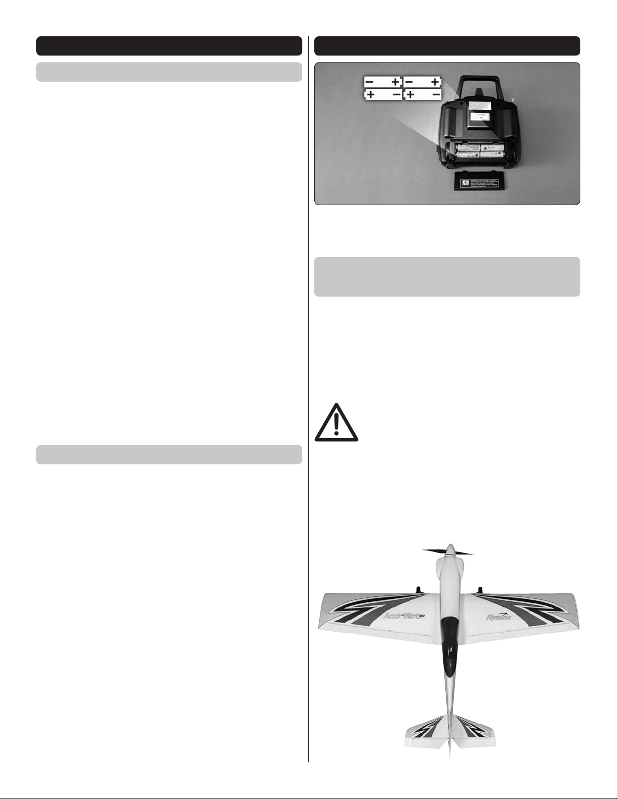
TTX404 TRANSMITTER
To install the batteries, slide the battery door down. Insert the
cells as shown in the diagram, making sure to note proper
polarity for each cell. Close the battery door.
Power Switch, LED,
and Low Battery Alarm
The red power LED should light when the power switch is
moved upwards to the “ON” position. The Tx should have
adequate power for fl ight when the LED is on constantly.
Anytime the LED begins to fl ash, accompanied by the
sounding of an audible tone, the Tx battery voltage has
dropped too low and operation of the model should NOT
be attempted!
WARNING! Never operate an R/C model
with weak Tx batteries! Reduced operational
range and/or possible loss of control of the
aircraft could result. Replace weak alkaline
batteries, or re-charge NiCd or NiMH batteries before
attempting a fl ight!
If during a fl ight the Tx LED starts to fl ash, accompanied
by the sounding of audible tones, it’s a warning that the
Tx batteries have become weak and the aircraft should be
landed as soon as possible!
3
Page 4
ADJUSTABLE STICKS
The length of both gimbal sticks can be adjusted as desired.
Loosen the set screw inside the center of the stick with a
2mm hex wrench. Rotate the stick end counter-clockwise to
lengthen the stick, or clockwise to shorten the stick. Once
the desired stick length is found, tighten the set screw with
the hex wrench.
CHARGE JACK
WARNING!! Do NOT attempt to recharge
alkaline batteries! The charge jack should
ONLY be used if rechargeable cells are used
in the transmitter.
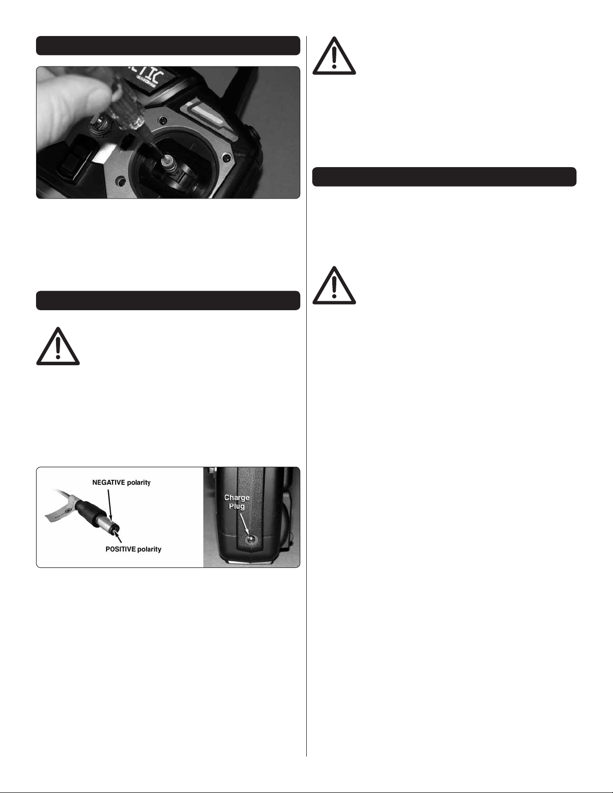
The TTX404 includes a built-in charge jack for convenient
recharging of NiCd or NiMH batteries, and is compatible
with charge leads designed for Futaba® brand transmitters.
(HCAP0101) This jack is NOT compatible with charge
leads for Hitec®, Airtronics®, JR® or Spektrum® radios. The
dimensions for compatible charge plugs are as shown in the
picture below.
To use the charge jack with optional rechargeable batteries,
fi rst remove the sticker that covers the charge jack on the
side of the Tx – making sure not to allow any object to be
inserted inside the jack itself. Next, insert the cells inside
the Tx’s battery compartment noting proper polarity. Make
sure the transmitter’s power switch is in the OFF position.
Connect a compatible charge lead to the jack and follow the
instructions included with the charger for charging of NiCd or
NiMH batteries that are rated at 4.8V.
Tactic’s optional TACP1000 rechargeable battery and wall
charger kit includes eight “AA” size rechargeable NiMH cells
and 110V AC wall charger, which is compatible with this Tx
and can be found at local retailers. Make sure to follow the
instructions included with the charge kit.
WARNING!! It’s not recommended to charge
batteries at greater than 1 amp through this
charge jack. Fast charging of NiCd and
NiMH batteries should ONLY be done with
chargers that are specifi cally designed to include the
peak-detection function which can automatically stop
charge when full charge is detected. Misuse, improper
charging, or over-charging of rechargeable cells can
result in damage to the cells that could include cell
rupture, explosion, or fi re!!
TRAINER FUNCTION
The TTX404 Tx includes a built-in wireless trainer function
– no trainer cable required! This trainer system connects a
teacher’s Tactic Tx to a student’s Tactic Tx by wireless
connection. Tactic’s wireless trainer function is not compatible
with trainer systems in any other brand radios.
IMPORTANT! Before attempting to fl y the
airplane, it’s very important to make sure all
reversing switches and trim lever adjustments
on the student’s Tx match the settings on the
teacher’s Tx! Otherwise, the airplane could suddenly veer
off in an unwanted manner when the teacher’s trainer switch
is pressed. Proper matching of the student and teacher’s
Tx settings should ensure that no unexpected movements
occur when the trainer switch is pressed. This is especially
true of the throttle control!
1. The Tx that was used to setup the controls on the
aircraft must be used by the TEACHER.
2. The student must use a separate Tactic Tx with
wireless trainer function.
3. Place the teacher and student’s transmitters within 1
meter of each other, and make sure the throttle stick
for each Tx is set to idle.
4. Turn ON the power switch for the Tx being held by the
student.
5. Pull and hold the trainer switch on the teacher’s Tx,
and then turn ON the teacher’s Tx power switch.
6. The LED on the teacher’s Tx will fl ash 3 times to
indicate it has become bound with the student’s Tx.
7. The teacher can then release his trainer switch.
8. Once both transmitters are bound together, power
can be applied to the receiver to prepare for fl ight.
When the training session has ended, with the model on the
ground and all power removed from the model, place both
transmitters within 1 meter of each other and simply turn the
power switch for both transmitters to the OFF position. This
will terminate the wireless link between both transmitters. If
additional training will be performed again, return to step 1
above to re-establish the wireless link between the teacher
and student’s transmitters.
4
Page 5

BIND THE RECEIVER TO THE Tx
REPLACEMENT PARTS LIST
ORDER NO. DESCRIPTION
Fuselage Set
One Piece Wing
Vertical Fin
Horizontal Stab
Main Landing Gear
Tail Wheel Assembly
Spinner Assembly
Foam Battery Hatch
11x8 Propeller
Prop Adapter
Brushless Motor
40 Amp ESC
Hardware Set
Decal Sheet
GP 3S LiPo Balancing Smart Charger w/AC/DC
Tactic TTX404 4-Channel 2.4GHz Radio System
Tactic TT624 6-Channel 2.4GHz Receiver
LiPo Battery 3S 1800 mAh
FLZA6223
FLZA6224
FLZA6225
FLZA6226
FLZA6227
FLZA6228
FLZA6229
FLZA6230
FLZA6231
FLZA6232
FLZA6233
FLZA6234
FLZA6235
FLZA6236
GPMM3318
TACJ2404
TACL0624
FLZA6024
For proper operation it’s necessary to “bind” the Tx and Rx
together electronically. This ensures sole communication
between the two, and prevents other transmitters from being
able to control the receiver.
1. Turn on the Tx.
2. Apply power to the Rx.
3. If the Rx LED fl ashes once and then stays on, the
Rx is already bound to the Tx and you can skip to
the next section. Otherwise, insert a small diameter
screwdriver through the hole marked “BIND” and
press the pushbutton until the Rx LED glows red and
then turns off after about one second.
4. Release the “BIND” button.
5. If the binding is successful, the Rx LED will fl ash once
and then remain ON.
6. Test for proper Tx / Rx functionality in the next section.
If the radio doesn’t appear to have become properly
binded, repeat steps 1– 6 above.
FAILSAFE FUNCTION
The included TR624 receiver has a failsafe feature which
engages in the event that the radio signal from the transmitter
somehow becomes interrupted. This safety feature causes
the servos to automatically move either to a certain position,
or hold their last position so to prevent the model from moving
in an erratic manner. Channels 1, 2, and 4 will enter a “hold”
mode, whereby the servos will lock in their last recognized
position.
Channel 3 will move to a pre-set position. The factory default
failsafe position for channel 3 is to move to 0% full throttle.
Motor/prop movement should stop if the receiver loses signal
from the transmitter. The throttle servo’s failsafe position can
be manually re-set to any other position if desired, as follows:
of acceptable quality, or if you need assistance with assembly,
contact Product Support. When reporting defective or missing
parts, use the part names exactly as they are written in the
Kit Contents list.
Hobbico Product Support Ph: (217) 398-8970 ext. 5
3002 N Apollo Drive Suite 1 Fax: (217) 398-7721
Champaign, IL 61822
E-mail: airsupport@hobbico.com
ORDERING REPLACEMENT PARTS
Replacement parts for the AcroWot MKII are available using
the order numbers in the Replacement Parts List that follows.
The fastest, most economical service can be provided by your
hobby dealer or mail-order company.
To locate a hobby dealer, visit the Hobbico web site at www.
hobbico.com. Select “Where to Buy” in the menu across the
top of the page and follow the instructions provided to locate
a U.S., Canadian or International dealer.
Parts may also be ordered directly from Hobby Services by
calling (217) 398-0007, or via facsimile at (217) 398-7721, but
full retail prices and shipping and handling charges will apply.
Illinois and Nevada residents will also be charged sales tax. If
ordering via fax, include a Visa® or MasterCard® number and
expiration date for payment.
Mail parts orders Hobby Services
and payments by 3002 N Apollo Drive, Suite 1
personal check to: Champaign IL 61822
Be certain to specify the order number exactly as listed in the
Replacement Parts List. Payment by credit card or personal
check only; no C.O.D.
If additional assistance is required for any reason contact
Product Support by e-mail at productsupport@hobbico.com,
or by telephone at (217) 398-8970.
IMPORTANT NOTE: Before manually resetting the
failsafe, make sure the servo reversing switches are in the
correct position for the application.
1. Apply power to the Tx and Rx.
2. If using an ESC, do NOT arm the ESC. Do NOT attempt
3. Move the Tx throttle stick to the desired position for the
4. Press and hold the “Bind” button on the receiver, and the
Before starting to build, take an inventory of this kit to make
sure it is complete, and inspect the parts to make sure they
are of acceptable quality. If any parts are missing or are not
to adjust the throttle’s failsafe position if the ESC is
armed.
throttle control to move if the Rx goes to failsafe.
Rx’s LED should blink twice. Release the Bind button,
and the receiver’s LED should turn on (stop fl ashing).
The Tx and Rx should now be bound, with the throttle
failsafe in the new position as set above.
KIT INSPECTION
5
Page 6

LED SCHEME
Use this table to determine charge action.
RED LED
OFF
OFF
Solid ON
Solid ON
Flashing
GREEN LED
Solid ON
Flashing
Solid ON
OFF
Flashing
ACTION
No battery is connected
Conditioning battery
Battery charging
Charge complete
ERROR*
*Possible sources of battery error may include a highly unbalanced
pack, charger timed out, or one cell of the pack which is low voltage. In
the case of a battery error, please remove the battery pack from the
charger and inspect it carefully for swelling or any other damage, such
as broken wires.
CONTENTS
Fuselage
1.
Wing
2.
Stabilizer/Elevators
1
5
8 9
3.
Vertical Fin/Rudder
4.
6
7
3
2
PREPARATIONS
Before starting to assemble the AcroWot MKII, we recommend
charging the fl ight battery. Then, when you are ready to set
up the radio system, the motor battery can be used to power
the receiver.
Charge the Battery
4
Main Landing Gear
5.
Flight Battery
6.
Spinner/Propeller
7.
Control Horn
8.
Tail Wheel Assembly
9.
3. If the battery was completely discharged, the RED and
GREEN LEDs will start to fl ash after 2-hours and 40-minutes.
The charger has a built-in safety timer.
4. Disconnect the battery from the charger, wait for the GREEN
LED to be lit, and then reconnect the battery to the charger.
5. It will take approximately 2-1/2 to 3 hours to complete the
charge. When the battery is fully charged, the GREEN
LED will turn OFF. Remove the battery from the charger
at this time.
6. Charging time depends on the level of discharge of the
battery and if the battery cells were unbalanced.
The following is an overview of how to charge your motor
battery using the ElectriFly Smart Charger. If you are using a
different LiPo charger, carefully follow the instructions included
with the charger.
1. Connect the input power to the charger. The GREEN LED
2. Connect the battery to be charged to the balance plug.
will be lit, indicating standby mode. The RED LED will be OFF.
The RED LED will also be lit, and remain RED during the
charging. Both LEDs should be lit solid while charging.
Battery Charging Precautions
● Be careful to avoid overcharging the battery. Only use a LiPo
approved charger. Never use a NiCd/NiMH peak charger.
6
Page 7

● Remember to check the temperature of the battery during
the charge. The battery should not get hot. If it does, unplug
the battery from the charger.
● Charge the battery at a maximum charge rate of 1.8 amps.
A higher charge rate will cause the battery to get hot.
● Never place the battery on combustible material or leave it
unattended while charging.
● Never charge the battery in the plane.
● We recommend that a balancing charger be used to charge
the battery. A properly cared for battery will last a long time. If
the battery pack is continually charged without balancing the
individual cells, the life of the battery pack will be shortened.
Battery Recycling
Attention: The AcroWot MKII is powered by a rechargeable
battery. At the end of the battery’s useful life, under various
state and local laws, it may be illegal to dispose of the battery
into the municipal waste system. Check with your local solid
waste offi cials for details in your area for recycling options or
proper disposal. We encourage contacting your local recycling
center for more information.
ASSEMBLE THE ACROWOT MKII
3. Fit the vertical fi n in place, making sure it is fully seated
❏
in the notch in the fuse.
1. Install the main landing gear onto the fuselage using
❏
two 3x15mm machine screws and thread locking compound.
Note the orientation of the gear in the photo.
2. Slide the horizontal stabilizer into the slot in the fuselage.
❏
Align the holes in the stab with the holes in the fuse.
4. Secure the fi n and stab in place with two 3x18mm
❏
machine screws as shown.
5. Fit the tail wheel assembly onto the underside of the
❏
fuse and push the tail wheel tiller wire into the molded groove
in the rudder. Secure the tail wheel assembly with a 2x10mm
self-tapping screw.
7
Page 8

6. Install the rudder control horn onto the rudder using
❏
two 2x8mm self-tapping screws and the rudder control horn
backplate. Note that the control horn captures the tail wheel
tiller wire in the rudder.
7. Remove the 90 degree pushrod connector from the rudder
❏
pushrod. Fit the 90 degree bend in the rudder pushrod wire
into the outer hole of the rudder control horn. Reattach the
90 degree pushrod connector, making sure the connector is
properly snapped into place.
9. Loosen the screws in the elevator and rudder servo arms.
❏
Temporarily power the receiver by turning on your transmitter (if
you are using the AnyLink adapter, refer to the AnyLink manual
for additional instructions) and connecting the fl ight battery
to the ESC in the battery compartment. Center the elevators
and rudder (also be sure your trim dials on the transmitter are
centered). Tighten the screws in the servo arms with thread
locking compound.
8. Install the elevator pushrod in the outer hole of the elevator
❏
control horn in the same manner as you did the rudder pushrod.
8
Page 9

10. Connect the Y-harness attached to the aileron servo
❏
leads to the receiver. Fit the wing in place on the fuselage
and secure it using a 4x12mm machine screw.
11. As you did with the elevators and rudder, center the
❏
ailerons and tighten the screws in the aileron servo arms with
thread locking compound, with the Rx powered.
12. Fit the spinner backplate onto the prop adapter shaft
❏
followed by the propeller, prop washer, and prop nut. Thoroughly
tighten the nut onto the shaft. Install the spinner cone onto
the backplate with the included screws.
13. Fit the fl ight battery into the battery compartment in
❏
preparation for checking the center of gravity of the plane.
Install the battery hatch in place.
9
Page 10

Set the Control Throws
To ensure a successful fi rst fl ight, set up your AcroWot MKII
according to the control throws specifi ed in this manual. The
throws have been determined through actual fl ight testing
and accurate record-keeping allowing the model to perform
in the manner in which it was intended. If, after you have
become accustomed to the way the AcroWot MKII fl ies,
you would like to change the throws to suit your taste, that
is fi ne. However, too much control throw could make the
model too responsive and diffi cult to control, so remember,
“more is not always better.”
These are the recommended control surface throws:
This is where your model should balance for the fi rst
fl ights. Later, you may experiment by shifting the C.G. 3/8”
[10mm] forward or 3/8” [10mm] back to change the fl ying
characteristics. Moving the C.G. forward will improve the
smoothness and stability, but the model will then be less
aerobatic (which may be fi ne for less-experienced pilots).
Moving the C.G. aft makes the model more maneuverable
and aerobatic for experienced pilots. In any case, start at
the recommended balance point and do not at any time
balance the model outside the specifi ed range.
LOW RATE
Up & Down
11/32"
ELEVATORRUDDERAILERONS
[9mm] 10°
Right & Left
1-1/16"
[27mm] 17°
Up & Down
11/32"
[9mm] 12°
NOTE: The throws are measured at the widest part of the
elevators, rudder and ailerons.
HIGH RATE
Up & Down
5/8"
[16mm] 18°
Right & Left
1-5/8"
[41mm] 27°
Up & Down
1/2"
[13mm] 18°
Balance the Model (C.G.)
More than any other factor, the C.G. (center of gravity/
balance point) can have the greatest effect on how a model
fl ies and could determine whether or not your fi rst fl ight will
be successful. If you value your model and wish to enjoy it
for many fl ights, DO NOT OVERLOOK THIS IMPORTANT
PROCEDURE. A model that is not properly balanced may
be unstable and possibly unfl yable.
At this stage the model should be in ready-to-fl y condition with
all of the components in place including the complete radio
system, battery, propeller, and spinner.
1. If using a Great Planes® C.G. Machine,™ set the rulers to
❏
2-7/16” [62mm]. If not using a C.G. Machine, use a fi ne-point
felt tip pen to mark lines on the top of wing on both sides of
the fuselage 2-7/16” [62mm] back from the leading edge. Apply
narrow (1/16” [2mm]) strips of tape over the lines so you will
be able to feel them when lifting the model with your fi ngers.
2. With the wing attached to the fuselage, and all parts of
❏
the model installed (ready-to-fl y) with battery pack, place the
model upside-down on a Great Planes CG Machine, or lift it
upside-down at the balance point you marked.
3. If the tail drops, the model is “tail heavy.” If possible,
❏
move the receiver forward to get the model to balance. If the
nose drops, the model is “nose heavy.” If possible, move the
receiver aft. If additional weight is still required, nose or tail
weight may be easily added by using Great Planes “stick-on”
lead (GPMQ4485). To fi nd out how much weight is required,
place incrementally increasing amounts of weight on the top
of the fuselage over the location where it would be mounted
inside until the model balances. Once you have determined
the amount of weight required, it can be permanently attached
with glue or screws.
4. IMPORTANT: If you found it necessary to add any weight,
❏
recheck the C.G. after the weight has been installed.
Balance the Model Laterally
1. With the wing level, have an assistant help you lift the
❏
model by the motor propeller shaft and the bottom of the fuse
under the TE of the fi n. Do this several times.
2. If one wing always drops when you lift the model, it means
❏
that side is heavy. Balance the airplane by adding weight to the
other wing tip. An airplane that has been laterally balanced
will track better in loops and other maneuvers.
10
Page 11

CHOOSE A GOOD FLYING SITE
If the wind is calm or very light, the AcroWot MKII will be
docile and easy to control. We do not recommend fl ying in
winds greater than 10mph [16km/h]. Find a fl ying site clear of
buildings, trees, power lines and other obstructions. Until you
know how much area will be required and have mastered fl ying
your AcroWot in confi ned spaces, a site at least the size of
two or three football fi elds should be adequate – a fl ying fi eld
specifi cally intended for R/C planes is best. Don’t fl y within fi ve
miles of R/C fl ying fi elds and never fl y near people – especially
children who can wander unpredictably into the fl ying area.
If planning a “dead-stick,” circle your AcroWot upwind of the
landing area until the motor quits and note the run time. When
you learn how much fl ight time you are getting you can adjust
your timer accordingly. Always be conservative so the motor
won’t quit unexpectedly and you will have enough battery to
land under power.
FLYING
The AcroWot MKII is a great-fl ying model that fl ies smoothly
and predictably. The AcroWot does not, however, possess
the self-recovery characteristics of a primary R/C trainer and
should be fl own only by experienced R/C pilots.
Perform a Range Check
As a precaution, an operational ground range test should
be performed before the fi rst fl ight each time you go out.
Performing a range test is a good way to detect problems that
could cause loss of control such as low batteries, defective or
damaged radio components or radio interference. This usually
requires an assistant and should be done at the actual fl ying
site you will be using.
First switch on the transmitter, then install the fully-charged
battery into the fuselage. Connect the battery and install the
battery hatch.
Remember, use care not to “bump” the throttle stick.
Otherwise, the propeller will turn and possibly cause
damage or injury.
To range check the Tactic TTX404 radio control system, switch
on the transmitter and connect the motor battery to the ESC.
Set the model on the ground and have an assistant hold the
model. Walk 100’ (30m) from the model and while pointing
the transmitter at the plane, operate the controls ensuring
that the plane’s surfaces operate according to the transmitter
inputs. Operate the motor at different rpm. Have your assistant
alert you if the controls quit responding or move suddenly or
erratically. If you are using a different radio control system,
follow the instructions that came with your radio control system
to perform a ground range check. If the controls aren’t working
correctly or if anything seems wrong, don’t fl y the model until
you fi nd and correct the problem. Make certain all the servo
wires are securely connected to the receiver and the transmitter
batteries are in good condition.
Takeoff
Before you get ready to takeoff, see how the model handles
on the ground by doing a few practice runs at low speeds
on the runway. Hold “up” elevator to keep the tail wheel on
the ground. If necessary, adjust the tail wheel so the model
will roll straight down the runway. If you need to calm your
nerves before the maiden fl ight, bring the model back into
the pits. Top off the battery charge, then check all fasteners
and control linkages for peace of mind.
Remember to take off into the wind. When you’re ready, point
the model straight down the runway, hold a bit of up elevator
to keep the tail on the ground to maintain tail wheel steering,
then gradually advance the throttle. As the model gains
speed decrease up elevator allowing the tail to come off the
ground. One of the most important things to remember with
a tail dragger is to always be ready to apply right rudder to
counteract motor torque. Gain as much speed as your runway
and fl ying site will practically allow before gently applying up
elevator, lifting the model into the air. At this moment it is likely
that you will need to apply more right rudder to counteract
motor torque. Be smooth on the elevator stick, allowing the
model to establish a gentle climb to a safe altitude before
turning into the traffi c pattern.
Flight
For reassurance and to keep an eye on other traffi c, it is a
good idea to have an assistant on the fl ight line with you. Tell
him to remind you to throttle back once the plane gets to a
comfortable altitude. While full throttle is usually desirable for
takeoff, most models fl y more smoothly at reduced speeds.
Monitor Your Flight Time
Monitor and limit your fl ight time using a timer (such as one
on a wrist watch or in your transmitter if yours has one).
When the batteries are getting low you will usually notice a
performance drop before the ESC cuts off motor power, so
when the plane starts fl ying slower you should land. To avoid
an unexpected dead-stick landing on your fi rst fl ight, set your
timer to a conservative 4 minutes (in most conditions the
AcroWot MKII will usually fl y for approximately 5 minutes, but
this can vary). When your alarm sounds you can either land
right away, or if you are an experienced pilot you may continue
to fl y until the motor fi nally quits. Then, glide it in for a landing.
11
Page 12

Take it easy with the AcroWot MKII for the fi rst few fl ights,
gradually getting acquainted with it as you gain confi dence.
Adjust the trims to maintain straight and level fl ight. After
fl ying around for a while, and while still at a safe altitude with
plenty of battery charge, practice slow fl ight and execute
practice landing approaches by reducing the throttle to see
how the model handles at slower speeds. Add power to see
how she climbs as well. Continue to fl y around, executing
various maneuvers and making mental notes (or having your
assistant write them down) of what trim or C.G. changes may
be required to fi ne tune the model so it fl ies the way you like.
Mind your battery charge, but use this fi rst fl ight to become
familiar with your model before landing.
Landing
To initiate a landing approach, lower the throttle while on the
downwind leg. Allow the nose of the model to pitch downward
to gradually bleed off altitude. Continue to lose altitude, but
maintain airspeed by keeping the nose down as you turn onto
the crosswind leg. Make your fi nal turn toward the runway (into
the wind) keeping the nose down to maintain airspeed and
control. Level the attitude when the model reaches the runway
threshold, modulating the throttle as necessary to maintain
your glide path and airspeed. If you are going to overshoot,
smoothly advance the throttle (always ready on the right rudder
to counteract torque) and climb out to make another attempt.
When you’re ready to make your landing fl are and the model
is a foot or so off the deck, smoothly increase up elevator until
it gently touches down. Once the model is on the runway and
has lost fl ying speed, hold up elevator to place the tail on the
ground, regaining tail wheel control.
One fi nal note about fl ying your model. Have a goal or fl ight
plan in mind for every fl ight. This can be learning a new
maneuver(s), improving a maneuver(s) you already know,
or learning how the model behaves in certain conditions
(such as on high or low rates). This is not necessarily to
improve your skills (though it is never a bad idea!), but more
importantly so you do not surprise yourself by impulsively
attempting a maneuver and suddenly fi nding that you’ve run
out of time, altitude or airspeed. Every maneuver should be
deliberate, not impulsive. For example, if you’re going to do a
loop, check your altitude, mind the wind direction (anticipating
rudder corrections that will be required to maintain heading),
remember to throttle back at the top, and make certain you
are on the desired rates (high/low rates). A fl ight plan greatly
reduces the chances of crashing your model just because
of poor planning and impulsive moves. Remember to think.
Have a ball! But always stay in control
and fl y in a safe manner.
GOOD LUCK AND GREAT FLYING!
Name
Address
City, State, Zip
This model belongs to:
AMA Number
Phone Number
12
 Loading...