

Page 1

Please read through this instruction booklet to THOROUGHLY familiarize yourself with the assembly and ight characteristics of this airplane prior to
assembly. Please inspect all parts carefully before starting assembly! If any parts are missing, broken or defective, or if you have any questions about
the assembly or ying of this airplane, please call us at (217) 398-8970 and we’ll be glad to help.
Flyzone® guarantees this kit to be free from defects in both material and workmanship at the date of purchase. This warranty does not
cover any component parts damaged by use or modication. In no case shall Flyzone’s liability exceed the original cost of the
purchased kit. Further, Hobbico, Inc. reserves the right to change or modify this warranty without notice. In that Hobbico, Inc. has no control
over the nal assembly or material used for nal assembly, no liability shall be assumed nor accepted for any damage resulting from the
use by the user of the nal user-assembled product. By the act of using the user-assembled product, the user accepts all resulting liability.
If the buyer is not prepared to accept the liability associated with the use of this product, the buyer is advised to return this kit
immediately in new and unused condition to the place of purchase. To make a warranty claim send the defective part or item to Hobby
Services at the address below:
Include a letter stating your name, return shipping address, as much contact information as possible
(daytime telephone number, fax number, e-mail address), a detailed description of the problem and a
photocopy of the purchase receipt. Upon receipt of the package, the problem will be evaluated as quickly
as possible.
© 2016 Hobbico®, Inc. All rights reserved. Printed in China FLZA2300/2302 Mnl
ASSEMBLE ONLY WITH ADULT SUPERVISION
This product is suitable only for people of 14 years and older.
WARRANTY
Hobby Services
3002 N. Apollo Dr. Suite 1
Champaign IL 61822 USA
®
™
A
SSEMBLE ONLY WITH ADULT SUPERVISION
®
Page 2

2
This device complies with part 15 of the FCC rules. Operation is subject to the following two conditions.
(1) This device may not cause harmful interference.
(2) This device must accept any interference received, including interference that may cause
undesired operation.
NOTE: THE MANUFACTURER IS NOT RESPONSIBLE FOR ANY RADIO OR TV INTERFERENCE CAUSED BY UNAUTHORIZED MODIFICATIONS
TO THIS EQUIPMENT. SUCH MODIFICATIONS COULD VOID THE USER’S AUTHORITY TO OPERATE THE EQUIPMENT.
FCC REQUIREMENT
CE COMPLIANCE INFORMATION FOR THE EUROPEAN UNION
Instructions for Disposal of Waste Equipment by Private Users in the European Union: This symbol on the product
or its packaging indicates this product must not be disposed of with other household waste. Instead, it is the user’s
responsibility to dispose of their waste equipment by handing it over to a designated collection point for the recycling
of waste electrical and electronic equipment. The separate collection and recycling of your waste equipment at the
time of disposal will help to conserve natural resources and ensure that it is recycled in a manner that protects human health
and the environment. For more information about where you can drop off your waste equipment for recycling, please contact
your local city ofce, your household waste disposal service or location where you purchased the product.
Declaration of Conformity:
Product: Tactic TTX403 2.4GHz 4-Channel Tx Rx
Item number: TACJ2403, Equipment class: 1
Tactic TTX403 transmitter and Tactic TR421 receiver: The objects
of the declaration described here are in conformity with the
requirements of the specications listed below, following the
provisions of the European 2006/95/EC Low Voltage Directive:
EN 60950-1:2006 Safety
The objects of the declaration described here are in conformity
with the requirements of the specications listed below, following
the provisions of the European R&TTE directive 1995/5/EC:
ETSI EN 300 328 V1.7.1 Technical requirements for radio equipment
ETSI EN 301 489-1 V1.8.1, 301 489-17 V1.3.2 General EMC
requirements for radio equipment
Tactic
c/o Hobbico, Inc.
2904 Research Road
Champaign, IL USA 61826
The associated regulatory agencies of the following
countries recognize the noted certications to this
product as authorized for sale and use.
UK DE DK BG SE FI FR
EE LV LT PL CZ SK HU
RO SI AT IT ES PT IE
NL LU MT CY GR
INCLUDED ITEMS
FCC AND ETSI
Check the parts against those shown. If
any parts are damaged or missing, please
call Hobby Services at: (217) 398-8970.
Note: Tx-R version (FLZA2302) does not
include transmitter. It does include a 1S
charger (not pictured).
Page 3

3
Your Micro B-25 Mitchell should not be considered a toy, but rather a sophisticated, working model that functions very
much like a full-size airplane. Because of its performance capabilities, the Micro B-25 Mitchell, if not assembled and
operated correctly, could possibly cause injury to yourself or spectators and damage to property.
1. Operate the plane according to the instructions. DO NOT alter or modify the model. If you make any modifications,
you void your warranty.
2. Test the operation of the model before each flight to ensure that all equipment is operating properly and that the
model remains structurally sound.
3. Fly only indoors or outdoors on very calm days (with wind speeds less than 5mph) and in large open areas free of
trees, people, buildings, or any other obstacles.
4. Although the Micro B-25 Mitchell is designed to be easy to fly, it is not for the first-time pilot. We strongly recommend
getting assistance from an experienced pilot for your first flights. If you’re not a member of an R/C club, your local
hobby shop has information about clubs in your area whose membership includes experienced pilots. You can also
contact the National Academy of Model Aeronautics (AMA) which has over 2,500 chartered clubs across the country.
Instructor training programs and insured newcomer training are available through any of these clubs. Contact the
AMA at the following address or toll-free phone number:
Academy of Model Aeronautics
5151 East Memorial Drive Ph. (800) 435-9262
Muncie, IN 47302-9252 Fx. (765) 741-0057
www.modelaircraft.org
The R/C model hobby becomes more and more enjoyable as your experience grows. Your chances for success and graduation
to higher levels are very good if you take your time and follow the flying instructions carefully and completely. We hope you
enjoy flying your Micro B-25 Mitchell plane.
TRANSMITTER CAUTIONS
● Do not use rechargeable (NiCd) batteries.
● Do not mix old and new batteries.
● Do not mix alkaline, standard (carbon-zinc) or
rechargeable (NiCd) batteries.
BATTERY CHARGING PRECAUTIONS
❏
1. Always remove the battery from your Micro B-25
Mitchell before charging.
❏
2. Do not leave a charging battery unattended! Unplug
the battery if it gets warm, even if the charge LED
has not gone out.
❏
3. Use only the charger that comes with your Micro
B-25 Mitchell!
WARNING: Misuse or malfunction may overheat the
battery and charger, resulting in personal injury or
damage to surroundings.
PRECAUTIONS
LITHIUM POLYMER BATTERY RECYCLING
ATTENTION: The product you have
purchased is powered by a rechargeable
battery. At the end of the battery’s useful
life, under various state and local laws, it
may be illegal to dispose of this battery
into the municipal waste system. Check with your local
solid waste officials for details in your area for recycling
options or proper disposal.
WARNING: This product contains a chemical known
to the State of California to cause cancer.
Page 4

ASSEMBLE THE MICRO B-25 MITCHELL
4
RED to RED
1. Plug the white micro
connector from the ESC
into the receiver board. Be
careful to plug the battery
in correctly.
3. Attach the wing.
2. Connect the power lead.
4. Insert the main landing gear. 5. Insert the nose gear.
#2 x 3/8" [9.5mm]
Sheet Metal Screws
Excess
Wire
Page 5

5
● Ailerons: The flight control on the airplane that controls the ability of the airplane to bank left and right.
● Center of Gravity (C.G.): Point at which the aircraft must balance in order to fly properly.
● Elevator: The flight control that controls pitch attitude. By adding power and pitching up, you can make the model
climb or loop.
● Glide Slope: The proper path for an airplane approaching a landing strip.
● Lithium Polymer (LiPo) Battery: Rechargeable battery which is used to power the airplane. LiPo batteries are lighter
and smaller than most other types of rechargeable batteries.
● Receiver: The unit in the aircraft that receives the signal from the transmitter to provide the input to the servos.
● Rudder: The flight control that controls the yaw (turning left or right).
● Servo: The device on the model that moves the flight controls.
● Transmitter (TX): The hand-held unit that sends the signals to the control unit, or receiver (RX), in the aircraft.
GLOSSARY
PREPARE THE TTX403 TRANSMITTER
For more information on the Tactic Radio System included with the Micro B-25 RTF version Mitchell visit www.tacticrc.com
Push and slide
to remove the
battery door.
Install (5) “AA” batteries.
Leave the TTX403
switched off.
Page 6

Leave the TTX403
unpowered.
Push down and slide to
open the charger cover.
Illuminated green light indicates charging.
(It may be necessary to cycle the on/off switch
to begin charging.) When the LED goes out,
charging is complete.
Insert battery to charge.
Make sure the battery
plug is oriented properly
before inserting.
6
CHARGE THE 3.7V 250MAH LIPO BATTERY
Do not use the charge feature while flying the Micro B-25 Mitchell!
1. Install the (5) AA batteries in the included 1S charger using the
polarity diagram shown in the battery compartment.
2. Plug the 3.7V battery into the charger as shown. The illuminated
LED indicates charging.
Warning: Do not connect the battery other than in the
orientation shown!
3. When the LED goes out, charging is complete.
TX-R ONLY: CHARGE THE 3.7V 250MAH LIPO BATTERY
Page 7

7
Illuminated red light
indicates the TTX403
is powered and transmitting.
Aileron and
Elevator Trims
Throttle/Rudder/
Nosewheel
Steering Control
Leave the left stick
(throttle control) in
the minimum position
during linking.
Power Switch
Throttle Trim
TRIM ADJUSTMENT
Full extent .................. Centered................. Full extent
Constant «beep» .........Single «beep» .........Constant «beep»
Nose Wheel Steering
and Rudder Trim
Aileron/Elevator Control
TTX403 FUNCTIONS
LINKING TO MICRO TX-R AIRCRAFT
Micro Tx-R aircraft include a receiver that auto-links to a Tactic transmitter. Once the receiver is powered, it will
link automatically to a present and compatible Tactic SLT 2.4GHz signal. Please follow these steps to safely link
your transmitter and aircraft the rst time.
1. Always power the transmitter or AnyLink rst.
2. Make sure the throttle stick is down.
3. Plug in the battery to the aircraft.
HELPFUL TIP: If you are going to y with a group, pre-link your transmitter and receiver prior to arriving at the
ying location.This must be done in an environment free of Tactic SLT 2.4GHz signals. Pre-linking ensures that
familiarity is established between your transmitter and receiver. Familiarity guarantees that as long as your
transmitter is powered rst, your receiver will link to your transmitter regardless of the other compatible signals
in the environment.
AnyLink must be in Normal Mapping (1 Beep) when Futaba®, Hitec® or Tower Hobbies transmitters
are used with Tx-R aircraft. If using a Spektrum® or JR® transmitter, AnyLink must be in Alternate
Mapping (2 Beeps). To change the mapping, consult your AnyLink instruction manual.
TX-R ONLY: POWER ANYLINK OR A TACTIC 2.4GHZ TRANSMITTER
All trademarks are property of their respective owners.
Page 8

Keep hands clear of the propellers during battery installation and removal.
Remove nose cone. Use two
ngers to secure connector during
battery installation and removal.
Press battery into
place to secure.
Replace nose cone.
Right stick moves left, left aileron moves
up and right aileron moves down, causing
the aircraft to bank to the left.
Left stick moves left, rudders move
left, causing the aircraft to yaw left.
Nosewheel points left.
Right stick moves down, elevator moves up
causing the aircraft’s nose to pitch up.
8
INSTALLATION AND REMOVAL OF THE LIPO BATTERY
CHECK THE CONTROL SURFACE DIRECTION
Disconnect and remove the battery after each flight by holding the battery lead with two fingers and removing the battery
from the lead with the other hand. Do not yank or jerk the battery from the aircraft. This could dislodge the RX board
from the Micro B-25 Mitchell.
Page 9
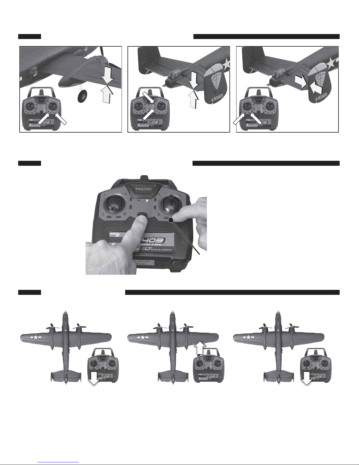
Press and hold one of the corresponding
control surface trim buttons and cycle the
power off and then on to reverse any control
surface direction. Hear a
«Beep Beep Beep»
sound.
9
If you ever need to reverse
the control throws, follow
this simple procedure.
CAUTION: Unplug the battery
in the model before attempting
to reverse the control throws.
Before ight, center elevator control
surface with elevator trim adjustment.
Before ight, center rudder control
surface with rudder trim adjustment.
Before ight, center aileron control
surface with aileron trim adjustment.
CENTER THE CONTROL SURFACES
REVERSE THE CONTROL THROWS
Keep hands and onlookers clear of propeller during arming and operation.
Switch on the transmitter and
position the throttle control stick
in the low or minimum position.
Plug the battery into plane.
Return the throttle control stick to
the minimum position. Hear
«Beep Beep»
sound. The motors are
now armed and the propellers will
operate if the throttle stick is raised.
Raise the throttle control stick
to the maximum or high position.
Hear a
«Beep»
sound.
ARM THE MOTORS
Page 10

10
CHOOSE A FLYING SITE
5 minute ight times
(outdoor)
8–10 minute ight times
(indoor)
INDOOR
FACILITY
ADJUSTMENT OF RUDDER AND ELEVATOR LINKAGES
To alter the center position of the rudder and elevator control throws, follow these steps. Be sure to unplug the battery
from the model before attempting to mechanically adjust the linkages.
With the transmitter powered and the battery plugged into the Micro B-25 Mitchell, walk 50' [15m] from the aircraft and
check the control functions for proper and smooth operation.
RANGE CHECK
50' [15m]
Page 11

11
If at anytime during operation, the controls or propellers
become jammed or unresponsive, reduce the power to the
propellers and land. Fix the problem before attempting to fly.
Take off (or hand launch) heading directly into the wind.
NOTE: If you hand launch, you can remove the landing gear
by gently pulling the landing gear wires straight out of the
mounts.When flying without landing gear, land on grass only
to minimize damage to the motor nacelles and fuselage. Cut
power to the motors completely just before the propellers
touch the ground to prevent any damage.
Hand launch with throttle set at ¾ to full power, wings level
and with a slight toss (it is not necessary to aggressively
throw this model to hand launch it).
Once in the air, gain altitude to allow yourself sufficient reaction time to make a correction during flight. Once you’re
comfortable, adjust the aileron and elevator trims one click at a time so that the Micro B-25 Mitchell flies straight and
level with the control sticks centered.
Concentrate on using small aileron control inputs so the model turns without banking the wings excessively. A slight
amount of up elevator may be necessary to maintain altitude going into a turn and the elevator will need to be returned
to neutral when coming out of a turn to avoid gaining altitude.
It’s recommended that you attempt to land before the motors lose power and don’t have enough voltage to maintain
altitude or the low-voltage cut-off stops the motors. Always land directly into the wind if possible. Gradually reduce
power when you are close to the landing spot and when close to the ground and about to touch down, pull the elevator
stick back slightly to raise the nose of the model and slow the landing speed to “flair” for landing. Unplug the battery
from the model and switch off the transmitter. Allow the motors to cool between flights.
FLYING THE MICRO B-25
To replace the propellers, rst make sure the battery is
unplugged. Remove the spinner by gently wiggling it and
breaking the glue joint that holds the spinner in place on
the propeller. Gently and carefully hold the motor shaft with
needle nose pliers or a hemostat to keep it from rotating and
gently unscrew the propellers from the shafts. As shown in
the picture, the left propeller unscrews clockwise and the
right propeller unscrews counterclockwise. BE SURE you
replace the propeller with the same rotating direction
propeller! The spinner can be glued back on the propeller
with a small amount of aliphatic (white) glue. Allow the glue
to dry suf ciently before ying the model. Gently pull on
the spinner to make sure it is really glued to the propeller.
PROPELLER REPLACEMENT
Page 12

Repairs can be made to the Micro B-25 Mitchell by using the following items:
● Thick Foam Safe CA (for parts adhesion), GPMR6072
● Foam safe CA accelerator, GPMR6035
● Formula 560 canopy glue, PAAR3300
● Two sets of needle nose pliers or hemostats, HCAR0625
● Hobby Knife (#11 blade), RMXR6900
● Clear tape
REPAIRS
Stock No. Description
FLZA6244 1S LiPo Charger
FLZA6565 Wing Parts Set
FLZA6566 Fuselage Parts Set
FLZA6567 Tail Surface Parts Set
FLZA6568 Nacelles Set
FLZA6569 Canopy Hatch
FLZA6570 Tail Gunner Canopy
FLZA6571 Wheels/landing Gear Set
FLZA6572 Propeller Set (L&R)
Stock No. Description
FLZA6573 Spinner Set (L&R)
FLZA6574 Plastic Parts Set
FLZA6575 Motor Set (L&R)
FLZA6576 Aileron Servos Set
FLZA6577 Receiver/ESC/Servos Board
FLZA6578 Gearbox Parts Set (1 set)
GPMP0770 1S 3.7V 250mAh 20C LiPo
TACJ2403 TTX403 4-Channel SLT Mini Transmittter
To order replacement parts for the Micro B-25 Mitchell, use the order numbers in the list below. Replacement parts are
available only as listed. Replacement parts are not available from Product Support, but can be purchased from hobby
shops or mail order/Internet order firms. If you need assistance locating a dealer to purchase parts from, contact:
Product Support
Phone: 217-398-0007
Fax: 217-398-7721
E-mail: productsupport@hobbico.com
REPLACEMENT PARTS
®
 Loading...