


FlyThisSim TouchTrainer® Set-up Guide
Setup Guide
FlyThisSim L.L.C.
102 Cross St. Suite 110
San Luis Obispo, CA 93401
(844) SIM-AVIO
(844) 746-2846
Thank you for purchasing the TouchTrainer® by FlyThisSim. We take pride in providing you with one of the most
advanced personal flight trainers on the market. Before we shipped the TouchTrainer® to you, we pre-configured all of
the software, calibrated all of the hardware, and tested the entire assembled system. However, we had to disassemble it
for shipping, so there are a there are a few preflight checks that need to be done. In about 45 minutes or less, you should
be ready for takeoff in your brand new TouchTrainer®.
Please be aware that because we are always improving our product, there may be minor differences between your system
and the one shown in this document.
Copyright FlyThisSim LLC 2013 Page 1

Table of Contents
List of Figures ......................................................................................................................................................................... 3
Chapter 1: Assembling Hardware ........................................................................................................................................... 6
Section 1: Unpacking .......................................................................................................................................................... 6
Section 2: Assembly ........................................................................................................................................................... 9
TouchTrainer® Table and Base ...................................................................................................................................... 9
TouchTrainer® Computer ............................................................................................................................................. 12
TouchTrainer® MAIN Monitor .................................................................................................................................... 14
TouchTrainer® AUX Monitor ...................................................................................................................................... 15
TouchTrainer® Joystick................................................................................................................................................ 16
TouchTrainer® Yoke and TPM Panel .......................................................................................................................... 18
TouchTrainer® Throttle Lever ..................................................................................................................................... 19
TouchTrainer® Rudder Pedals ..................................................................................................................................... 22
TouchTrainer® VISX Monitors .................................................................................................................................... 23
Chapter 2: System Startup..................................................................................................................................................... 27
Airplane Start-Up Procedures: Before you begin ............................................................................................................. 28
Cirrus Avidyne and Analog Start-Up Procedure .............................................................................................................. 29
Cirrus Perspective Start-Up Procedure ............................................................................................................................. 31
Steam Gauge (Analog) Start-Up Procedure ...................................................................................................................... 33
Garmin G1000 Start-Up Procedure ................................................................................................................................... 35
Diamond Analog Startup Procedure ................................................................................................................................. 37
Diamond G1000 Startup Procedure .................................................................................................................................. 39
Beech Analog Startup Procedure ...................................................................................................................................... 41
Beech G1000 Startup Procedure ...................................................................................................................................... 41
Piper Analog Startup Procedure ....................................................................................................................................... 42
Piper Avidyne Startup Procedure ...................................................................................................................................... 43
Shutdown Procedure (All Panels) ..................................................................................................................................... 44
Chapter 3: Standard Operating Procedures ........................................................................................................................... 45
Control Layout ................................................................................................................................................................... 45
Selecting an Aircraft ......................................................................................................................................................... 46
Instructors Operation Station (I.O.S.): Setting location, fuel, and weather ..................................................................... 47
Setting Time and Weather................................................................................................................................................. 48
Aircraft Failures ................................................................................................................................................................ 48
Loading a Scenario (NEW!!!) ........................................................................................................................................... 49
Page 2 Copyright FlyThisSim LLC 2013

FlyThisSim TouchTrainer® Set-up Guide
Logging time as an FAA approved Basic Aviation Training Device ............................................................................... 50
Chapter 4: Other Information ................................................................................................................................................ 50
Configuring X-Plane Settings ........................................................................................................................................... 50
Changing Graphics Settings .......................................................................................................................................... 50
Configuring Buttons and Switches ............................................................................................................................... 51
Fetching and Installing Nav Data Updates........................................................................................................................ 51
Upgrading SimAVIO ........................................................................................................................................................... 52
Using TeamViewer ........................................................................................................................................................... 52
Computer Specifications ................................................................................................................................................... 54
Product Warranties and Online Manuals .......................................................................................................................... 54
Computer Specifications for FTS RED ............................................................................................................................ 55
Product Warranties and Online Manuals .......................................................................................................................... 55
Chapter 5: Troubleshooting .................................................................................................................................................. 56
Chapter 6: Documentation .................................................................................................................................................... 68
FAA Approval Copy ......................................................................................................................................................... 68
Certificate of Title ............................................................................................................................................................. 71
List of Figures
Figure 1: Accessories, CDs, and Manual ................................................................................................................................. 8
Figure 2: USB Adapters ........................................................................................................................................................... 8
Figure 3: Leg Assembly for the TouchTrainer Table................................................................................................................ 9
Figure 4: Underside of TouchTrainer® base as packed ......................................................................................................... 10
Figure 5: Topside of TouchTrainer® Base .............................................................................................................................. 11
Figure 6: Attaching cables to the back of the computer....................................................................................................... 12
Figure 7: Plugging in Wi-Fi Adapter to Front of Computer for Commercial Edition ............................................................. 12
Figure 8: Connecting visual cables to the back of the VISX computer .................................................................................. 13
Figure 9: Connecting cables to the back of the 23" MAIN display ........................................................................................ 14
Figure 10: Affixing the MAIN monitor bracket ...................................................................................................................... 14
Figure 11: Affixing the MAIN monitor bracket to the base .................................................................................................. 15
Figure 12: Connecting cables to the AUX monitor ................................................................................................................ 15
Figure 13: Affixing the AUX monitor to the base .................................................................................................................. 16
Figure 14: Joystick location overview ................................................................................................................................... 16
Figure 15: Placing the joystick in the slot .............................................................................................................................. 17
Figure 16: Affixing the joystick in place ................................................................................................................................ 17
Figure 17: Installing the Yoke (View from under the table) .................................................................................................. 18
Copyright FlyThisSim LLC 2013 Page 3

Figure 18: Installing the TPM ................................................................................................................................................ 18
Figure 19: Nut Inserts for Linear Throttles ............................................................................................................................ 19
Figure 20: Twin Throttle Lever .............................................................................................................................................. 20
Figure 21: Hardware Required for Changing From Single to Twin Throttle Lever ................................................................ 20
Figure 22: Views from the Rear of the Single and Twin Throttles ........................................................................................ 21
Figure 23: Connecting the throttle USB cable....................................................................................................................... 21
Figure 24: Pushing the throttle cable through the notch in TouchTrainer® base ................................................................ 21
Figure 25: Adjusting the tension on the rudder pedals ........................................................................................................ 22
Figure 26: Disassembled VISX System ................................................................................................................................... 23
Figure 27: Bolting the left cross-member to the central member ........................................................................................ 23
Figure 28: Assembled Cross Members (viewing from the back) .......................................................................................... 23
Figure 29: Attaching the Cross Members to the Left Upright ............................................................................................... 24
Figure 30: Attaching the Assembly to the Right Upright ...................................................................................................... 24
Figure 31: Backside of a bolted VISX Monitor ....................................................................................................................... 24
Figure 32: Attaching the VISX Monitors ................................................................................................................................ 24
Figure 33: Plugging into the VISX Monitors .......................................................................................................................... 25
Figure 34: Placing the VISX System on the table .................................................................................................................. 25
Figure 35: Bolting the uprights to the bases ......................................................................................................................... 25
Figure 36: VisX Power Plug Located Behind the Center Monitor on the Underside of the Junction Box ............................ 26
Figure 37: TouchTrainer Power Plug Located at the Rear of the Base of the Left VisX Upright ........................................... 26
Figure 38: TouchTrainer® Supervisor startup screen ............................................................................................................ 27
Figure 39: Cirrus Avidyne Panel with no power .................................................................................................................... 29
Figure 40: Cirrus Avidyne Panel after engine start ............................................................................................................... 29
Figure 41: Cirrus Avidyne Panel ready for takeoff ................................................................................................................ 30
Figure 42: Cirrus Perspective Panel with no power .............................................................................................................. 31
Figure 43: Cirrus Perspective Panel after engine start ......................................................................................................... 31
Figure 44: Cirrus Perspective Panel with avionics activated ................................................................................................. 32
Figure 45: Cirrus Perspective Panel with Flight Plan display. ............................................................................................... 32
Figure 46: Cirrus Perspective Panel ready for takeoff .......................................................................................................... 32
Figure 47: Cessna Analog with no power .............................................................................................................................. 33
Figure 48: Cessna Analog after engine start ......................................................................................................................... 34
Figure 49: Cessna Garmin G100 with no power ................................................................................................................... 35
Figure 50: Cessna Garmin G1000 after essential bus powered on ....................................................................................... 35
Figure 51: Cessna Garmin G1000 after avionics bus powered on ........................................................................................ 36
Figure 52: Cessna Garmin G1000 ready for take-off ............................................................................................................ 36
Figure 53: Diamond Analog Panel with no power ................................................................................................................ 37
Figure 54: Diamond Analog Panel afteGNS-430 start ........................................................................................................... 37
Figure 55: Diamond Analog Panel ready for takeoff ............................................................................................................. 38
Figure 56: Diamond G1000 Panel with no power ................................................................................................................. 39
Figure 57: Diamond G1000 Panel after MFD bootup ........................................................................................................... 39
Figure 58: Diamond G1000 Panel after engine start ............................................................................................................ 40
Figure 59: Diamond G1000 Panel ready for takeoff ............................................................................................................. 40
Figure 60: Bonanza Analog after Engine Start ...................................................................................................................... 41
Figure 61: Bonzana G1000 after Engine Start ....................................................................................................................... 42
Page 4 Copyright FlyThisSim LLC 2013

FlyThisSim TouchTrainer® Set-up Guide
Figure 62: Piper Arrow after Engine Start ............................................................................................................................. 43
Figure 63: Yoke Controls ....................................................................................................................................................... 45
Figure 64: Joystick Controls .................................................................................................................................................. 45
Figure 65: SimAVIO command buttons ................................................................................................................................. 46
Figure 66: Aircraft Selection Folders ..................................................................................................................................... 46
Figure 67: IOS screen ............................................................................................................................................................ 47
Figure 68: Weather and Time ............................................................................................................................................... 48
Figure 69: Aircraft Failures ............................................................................................................................................ 48
Figure 70: Nav Data icon on the desktop .............................................................................................................................. 51
Figure 71: Popup downloads window ................................................................................................................................... 51
Figure 72: FTS Version Check Utility ..................................................................................................................................... 52
Figure 73: TeamViewer icon in the system tray ................................................................................................................... 52
Figure 74: TeamViewer options window .............................................................................................................................. 53
Figure 75: Options Menu ...................................................................................................................................................... 56
Figure 76: Configuring the Surround Displays options ......................................................................................................... 56
Figure 77: Locking the Taskbar ............................................................................................................................................. 57
Figure 78: Configure Surround Menu ................................................................................................................................... 57
Figure 79: Configure Display for Surround Menu ................................................................................................................. 57
Figure 80: Connect Displays as Shown .................................................................................................................................. 58
Figure 81: Apply Configurations ............................................................................................................................................ 58
Figure 82: Bezel Correction Selection ................................................................................................................................... 59
Figure 83: Bezel Width Adjustment Menu ............................................................................................................................ 59
Figure 84: Change Resolution Menu ..................................................................................................................................... 60
Figure 85: Setting Up Multiple Displays – Arranging the Main Touch Monitor .................................................................... 61
Figure 86: Setting up Multiple Displays - Arranging the Aux Monitor .................................................................................. 62
Figure 87: Screen Resolution window................................................................................................................................... 63
Figure 88: eGalaxTouch Configure Utility ............................................................................................................................. 64
Figure 89: Main display Monitor Mapping. Press the space bar on this screen .................................................................. 64
Figure 90: Aux Display Monitor Mapping. Tap the screen to map this display ................................................................... 64
Figure 91: The "Waiting for Connection" screen .................................................................................................................. 66
Figure 92: Certificate of Title Document Format .................................................................................................................. 71
Copyright FlyThisSim LLC 2013 Page 5

Chapter 1: Assembling Hardware
Basic Touch Trainer Items
#
Base
1
Planar
Monitor/Bracket
1
AUX Monitor/Bracket
1
Computer
1
Rudder Pedals/
Extensions
1
2
Rudder Floor Pads
2
Keyboard & Mouse
1
FAA Framed Letter
1
WiFi USB Dongle
1
X-Plane USB
(COMMERCIAL USE
ONLY)
1
Cirrus Hardware Items
#
Joystick
1
Throttle
1
Throttle Handle
1
Cessna Hardware Items
#
Yoke
1
Throttle
1
Beech Hardware Items
#
Twin Throttle
(attach bracket)
1
This chapter will guide you through the process of assembling your new TouchTrainer® so that it is ready to power up.
Following these directions exactly will guarantee that you have your TouchTrainer® assembled quickly and easily.
Hardware assembly should take between 15 and 30 minutes.
Section 1: Unpacking
First, carefully unpack and inspect the items delivered for transit damage. The contents delivered should match the
packing list found below. It is recommended that you save all packaging materials until the manufacturer’s warranty
period expires. See Chapter 4 for warranty information.
Table 1: Packing List
Page 6 Copyright FlyThisSim LLC 2013

FlyThisSim TouchTrainer® Set-up Guide
QTY
TOUCHTRAINER® HARDWARE
QTY
THROTTLE LEVER HARDWARE
6
M6x15 Bolts (2 in Joystick slot in base)
2
Thumbscrews
4
Vesa Pan Head Screws
QTY
VISX HARDWARE
QTY
TABLE LEG HARDWARE
4
M6x11 Bolts
4
Large Phillips Head Bolts
4
M6x15 Bolts
8
M6x11 Bolts
8
M6 Nuts
12
M4 Nuts
8
¼” Lock Washers
8
Nylon Washers
ITEM
#
Acer Monitor
3
VisX Horizontal R/L/C
VisX Vertical Left
VisX Vertical Right
3
1
1
Power Cable
1
ITEM
#
Table
1
Leg
2
Feet
2
Modesty Plate
1
ITEM
#
Hardware Packs
4 Bags*
ITEM
#
Allen Wrench
1
Screw/Socket Driver
1
Nut-Driver 7/10
2
ITEM
#
Windows 7 Disk
1
Motherboard Drivers Disk
1
X-Plane Disks (HOME USE ONLY)
1
TouchTrainer Disk
1
Optional Purchase Items:
Included in your shipment is an envelope containing several items needed to assemble your TouchTrainer®.
Table 2: Hardware Packs*
Copyright FlyThisSim LLC 2013 Page 7

Wireless Network Adaptor
(Comes plugged into
Computer)
Keyboard & Mouse Adaptor
(Comes plugged into
computer)
X-Plane Commercial Adaptor
(Not included for Home-Use
version)
Figure 1: Accessories, CDs, and Manual
Figure 2: USB Adapters
Page 8 Copyright FlyThisSim LLC 2013

FlyThisSim TouchTrainer® Set-up Guide
Modesty Plate
Attachment Inserts
Section 2: Assembly
This section will walk you through the complete assembly of your TouchTrainer® system from start to finish.
TouchTrainer® Table and Base
If you purchased a table along with your TouchTrainer®, then your plastic base will arrive fastened to the table. If you did
not purchase a table, you may skip to the next page.
To construct the table, unpack the two table legs and table, and place the table upside down on a flat surface.
1) First attach both legs to the bottom of the table using the M6 screws and your included Allen Wrench.
2) Next, attach the modesty plate to the inside of the legs using the 4 supplied screws
3) Attach the “feet” of the legs using the Philips Head large screws onto the leg pieces.
Figure 3: Leg Assembly for the TouchTrainer Table
Your TouchTrainer® comes pre-wired and your TouchTrainer® wires and components also come pre-labeled. The only
thing you need to do is connect like-numbered cables to their respective ports.
There are five main wire harnesses that connect all the components of your TouchTrainer®, shown in Figure 4 on the next
page.
Copyright FlyThisSim LLC 2013 Page 9

(A) Joystick
USB Jack
AUX Monitor
Harness
(B)Single/Twin
Throttle and Yoke
USB Jack
MAIN Monitor
Harness
Computer
Harness
Power
Junction Box
Computer Harness
o (1) Computer power
o (2) MAIN monitor HDMI
o (3) AUX monitor DVI
o (4) AUX monitor USB
o (5) MAIN monitor USB
o (6) X-Plane USB key (Commercial)
o (6) * Twin (for twin aircraft)
o (7) Rudder Pedals
o (8) Throttle Quadrant
o (9) Joystick (or Yoke)
o (D) Keyboard/Mouse Adapter
o (E) Wi-Fi USB Dongle
o (E) ** X-Plane USB key
o (F) **Wi-Fi USB Dongle
*The “Twin” should only be plugged in for twin engine configurations.
** If you have a commercial system, the X-Plane USB will be in (E) and Wi-Fi (E) will be plugged into (F) on the front
USB header.
NOTE: If you purchased a TouchTrainer® with a table, you may skip to the TouchTrainer® Computer Section.
1) Begin with the base upside down on a flat surface (Figure 4). Take note of the various wiring harnesses.
AUX Monitor Harness
MAIN Monitor Harness
(A) Joystick USB Jack
(B) Single Throttle USB Jack
(C) Twin Throttle USB Jack
Power Junction Box
o (L) *(VISX) VISX Primary DVI
o (R) *(VISX) VISX Primary HDMI
o (C) *(VISX) VISX Secondary DVI
o (10) Power
o (11) DVI
o (12) USB
o (13) Power
o (14) USB
o (15) HDMI
Figure 4: Underside of TouchTrainer® base as packed
Note: The cables pictured may look slightly different than those attached to your base.
Page 10 Copyright FlyThisSim LLC 2013

FlyThisSim TouchTrainer® Set-up Guide
MAIN Monitor
Harness
Computer
Harness
AUX Monitor
Harness
Joystick
Harness
Computer
Harness
2) Flip your TouchTrainer® base over and take note of where the cable harnesses are (Figure 5).
Figure 5: Topside of TouchTrainer® Base
Copyright FlyThisSim LLC 2013 Page 11

TouchTrainer® Computer
Rudder
Single Throttle
Wi-Fi Adapter
Main Monitor USB
Main Monitor
HDMI
Joystick/Yoke
AUX Monitor
DVI
X-Plane USB
Key2
Keyboard/Mouse
Receiver
Wi-Fi Adapter
2
Twin Throttle
1) Place the computer into the large slot on the back of the TouchTrainer® base.
Note: Do not power on the computer yet.
2) If you have a TouchTrainer® with a VisX system skip to step 3. For a TouchTrainer® without a VisX system,
connect all cables to the back of the computer as shown in Figure 6.
Figure 6: Attaching cables to the back of the computer
Note: If you purchased the TouchTrainer® Commercial edition, the X-Plane Commercial USB Key will be plugged into
port E, and the Wi-Fi Adapter will move to the front of the computer in port F, as shown in Figure 7:
Figure 7: Plugging in Wi-Fi Adapter to Front of Computer for Commercial Edition
3) For the TouchTrainer® VisX system, plug all cables into the rear computer ports EXACTLY as shown in Figure
6, except now you have 3 more inputs coming from the 3 VisX monitors, which plug into the slots as shown in
Figure 8.
Page 12 Copyright FlyThisSim LLC 2013

FlyThisSim TouchTrainer® Set-up Guide
Center VISX DVI
Right VISX HDMI
Left VISX DVI
MAIN Monitor HDMI
AUX Monitor DVI
4) Each cable should be labeled for the appropriate slots. Failure to plug devices into their correct slot could result in
connectivity issues. If you have the VISX system, you MUST wait until you have installed the external visual
before setting up the computer.
Figure 8: Connecting visual cables to the back of the VISX computer
Copyright FlyThisSim LLC 2013 Page 13

TouchTrainer® MAIN Monitor
Power
HDMI
USB
1) Connect the power, USB, and HDMI cables to the MAIN monitor (Figure 9).
Figure 9: Connecting cables to the back of the 23" MAIN display
2) Attach the MAIN monitor bracket using the four Vesa screws in the back of the MAIN monitor with a Phillips-
head screwdriver, (Figure 10).
Figure 10: Affixing the MAIN monitor bracket
Page 14 Copyright FlyThisSim LLC 2013

FlyThisSim TouchTrainer® Set-up Guide
USB
Power
DVI
3) Using the supplied Allen wrench, secure the MAIN monitor bracket to the base using M6x15 bolts (Figure 11).
Figure 11: Affixing the MAIN monitor bracket to the base
TouchTrainer® AUX Monitor
1) Connect the power, DVI, and USB cables to the AUX monitor (Figure 12).
Figure 12: Connecting cables to the AUX monitor
Copyright FlyThisSim LLC 2013 Page 15

2) Use the supplied Allen wrench to attach the AUX monitor to the base using M6x15 bolts (Figure 13).
Angled
M6x15 bolts
Joystick
Harness
Joystick
Harness
Joystick
Screw-holes
Figure 13: Affixing the AUX monitor to the base
TouchTrainer® Joystick
If your TouchTrainer® comes with a yoke and not a joystick, skip ahead to the yoke section.
1) The hole for the joystick is pre-cut and pre-drilled (Figure 14).
Figure 14: Joystick location overview
2) Attach the joystick USB cable to the joystick harness, feed the remaining cable through the hole, and place the
joystick into the slot (Figure 15).
Page 16 Copyright FlyThisSim LLC 2013

FlyThisSim TouchTrainer® Set-up Guide
Figure 15: Placing the joystick in the slot
3) Screw the two bracket clamps into the pre-drilled holes in the upper-right and lower-left corners of the slot
(Figure 16). This keeps the joystick in place during operation.
Figure 16: Affixing the joystick in place
Copyright FlyThisSim LLC 2013 Page 17

TouchTrainer® Yoke and TPM Panel
Toggle Clamp
TPM Bracket Captive Screws
If your TouchTrainer® does not come with a yoke and/or a TPM panel, skip this section.
1) The table has a slot cut for the Yoke, and a catch bracket on top. Slide the yoke into place and flip the toggle
clamps on the underside of the table to hold the yoke in place, as shown below, then connect the USB cables
appropriately to the cable labeled “Yoke A”.
Figure 17: Installing the Yoke (View from under the table)
2) The TPM panel comes pre-attached to a bracket with two captive screws that fits into a bracket on the right side
of the table. Slide the TPM panel into its slot on the underside of the table, as shown below, tighten the two
captive screws, and then connect the USB cables appropriately to the cable labeled “Single B”.
Figure 18: Installing the TPM
Page 18 Copyright FlyThisSim LLC 2013

FlyThisSim TouchTrainer® Set-up Guide
Screw Points
Single Throttle
Twin Throttle
TouchTrainer® Throttle Lever
If your TouchTrainer® does not come with a single or twin linear throttle, skip this section.
1) The base has nut insert holes located on the right side and on the front face of the base. For the single throttle,
insert the included thumbscrews into the rightmost and middle nut inserts, and for the twin throttle, insert the
thumbscrews into the rightmost and leftmost nut inserts (see Figure 19). Do not screw these in completely,
leaving a small gap between the head of the screw and the base.
Figure 19: Nut Inserts for Linear Throttles
2) If the bracket is already attached to your single lever, skip to step 4. To attach the bracket to your single throttle,
take the bracket included with your throttle and using 2 Vesa Pan Head screws, screw the bracket onto the back of
the throttle.
3) If the bracket is already attached to your twin throttle lever, skip to step 4. To attach the twin throttle bracket,
place the two throttles side by side, with the throttle whose cable is labeled “Single B” on the right when looking
from the back, see Figure 20. Using 4 Vesa Pan Head screws, screw the bracket onto the back of the two throttles.
You may need to change the handles to match the layout of your aircraft (the default layout is seen in Figure 20,
left to right T T P P M M).
Copyright FlyThisSim LLC 2013 Page 19

Single Throttle Bracket
Vesa Pan Head Screws
TPM knobs/caps
Twin Throttle Bracket
Figure 20: Twin Throttle Lever
4) Take your single or twin throttle lever and place it on the M6 screws you attached to the base, then screw those in
tightly using the included Allen wrench.
5) The final step in the setup of your throttle lever is to connect the USB cables appropriately under the table,
directly behind the throttle lever you have just installed.
Note: You must connect the cables to the appropriate matching cables labeled under the table.
Changing Between a Single and Twin Throttle:
1) Remove the throttle from the TouchTrainer®, and unscrew the bracket from the back of the throttle.
Figure 21: Hardware Required for Changing From Single to Twin Throttle Lever
2) Bring together the two throttles, with the throttle including the wire labeled “Single B” on the right side of the
two (when looking at them from the back, where you mount the bracket, see Figure 21).
3) Next, attach the twin throttle bracket to the back of the throttles using the same Vesa Pan Head screws used
for the single. Please note that the twin throttle bracket requires 4 of the Vesa screws while the single only
requires 2.
Page 20 Copyright FlyThisSim LLC 2013

FlyThisSim TouchTrainer® Set-up Guide
Screw Points
Throttle With Cable
Labeled “Single B”
Throttle With Cable
Figure 22: Views from the Rear of the Single and Twin Throttles
Once you have the bracket attached to the appropriate throttle for your aircraft, you are now ready to attach it to the
TouchTrainer® Base. Before setting the throttle onto the thumbscrews, you must connect the cable. If you purchased a
table with your TouchTrainer®, only do step 1.
1) Attach the throttle USB cable to the USB port labeled “B” on the underside of the base.
Figure 23: Connecting the throttle USB cable
2) Push the throttle cable into the notch in the base (Figure 24)
Figure 24: Pushing the throttle cable through the notch in TouchTrainer® base
3) Now place the throttle onto the thumbscrews and tighten for rigidity.
Copyright FlyThisSim LLC 2013 Page 21

TouchTrainer® Rudder Pedals
Pedal
Tensioner
Rudder
Extensions
Your TouchTrainer® system comes with rudder pedals which will need to be set up.
1) Place the pedals underneath the table or desk you will be using. Depending on your floor surface, you may need
to use the included Velcro strips or place a rubber mat underneath the pedals in order to keep them from slipping
when in use. Attach the Rudder Pedal Extensions to the pedals.
2) Adjust the tension in the pedals to a setting that feels comfortable. A good rule of thumb is to increase the tension
until the pedals feel too heavy; then loosen the tension a quarter turn (Figure 25).
Figure 25: Adjusting the tension on the rudder pedals
Page 22 Copyright FlyThisSim LLC 2013

FlyThisSim TouchTrainer® Set-up Guide
RIGHT
CENTER
LEFT
TouchTrainer® VISX Monitors
Note: This section only applies to TouchTrainer® systems that include the three VISX monitors. If your system does not
include VISX monitors, then your TouchTrainer® is completely assembled and ready for flight. Refer to the assembly
video for more details.
Figure 26: Disassembled VISX System
1) Bolt the left and right members to the central black member using the included M6 lock washers and nuts. Note
that the members are labeled LEFT, CENTER, and RIGHT as per their position while facing the front of the
TouchTrainer®.
Note: It is recommended that the VISX assembly be performed separate from the main touch trainer base to
reduce the risk of damage and improve the ease of assembly.
Figure 27: Bolting the left cross-member to the central member
Figure 28: Assembled Cross Members (viewing from the back)
Copyright FlyThisSim LLC 2013 Page 23

2) Attach the assembled horizontal members to the two vertical uprights via the red flanged brackets, starting with
the left red bracket. This is usually easier to do with the assembly on the ground. Use the same M6 lock washers
and nuts as when assembling the cross members.
Figure 30: Attaching the Assembly to the Right Upright
Figure 29: Attaching the Cross Members to the Left Upright
3) Bolt the monitors to the VISX assembly, ensuring the labels are correctly oriented. The monitors come
permanently affixed with four threaded studs. Use the included M4 nuts to secure the monitors to the VISX
assembly. Do not fully tighten the nuts until the monitors are in their final position; leaving the nuts slightly loose
allows the monitors to slide in their slots for easy positioning.
Figure 31: Backside of a bolted VISX Monitor
Note: Ideally, the monitors should be installed in this order: Center, Right, Left.
Figure 32: Attaching the VISX Monitors
Page 24 Copyright FlyThisSim LLC 2013

FlyThisSim TouchTrainer® Set-up Guide
These only bolted if a
Table was purchased
4) Connect the wires from the central junction box to their corresponding plugs, as shown below.
Figure 33: Plugging into the VISX Monitors
5) Place the entire VISX assembly on the TouchTrainer® base and insert two M6x15 bolts and nylon washers it into
the nutserts located on the sides of the base, through the red uprights. This step may require two people. For
optional added stability, the assembly may be bolted into the table using M6x11 bolts.
Figure 34: Placing the VISX System on the table
Figure 35: Bolting the uprights to the bases
Copyright FlyThisSim LLC 2013 Page 25

6) Connect all wires from the central junction box into the appropriate plugs, as detailed in the TouchTrainer®
computer section.
7) The last step is to connect the AC Power Cables into the outlets on the TouchTrainer®. One Power cable plugs
into the plastic base and if you have a VisX TouchTrainer® plug the second power cable into the outlet on the
center cross-member behind the center monitor.
Figure 36: VisX Power Plug Located Behind the Center Monitor
on the Underside of the Junction Box
NOTE: YOU MUST PLUG BOTH POWER CABLES IN AND MAKE SURE ALL CABLES ARE
CONNECTED BEFORE POWERING ON THE TOUCHTRAINER®. FAILURE TO DO SO WILL RESULT
IN A RECONFIGURATION OF NVIDA SURROUND. (SEE TROUBLESHOOTING Pg.48)
Figure 37: TouchTrainer Power Plug Located at the Rear of the
Base of the Left VisX Upright
Before powering up your TouchTrainer®, make sure your mouse is powered on. To verify this, turn it over and see if the
red laser is on. If it is not, turn your mouse on before turning on your computer. The mouse and keyboard are preconfigured for use with your TouchTrainer®.
Congratulations, your TouchTrainer® is now completely assembled! You’re now ready to power up your TouchTrainer®
and start flying.
Copyright FlyThisSim LLC 2012 Version 2.8.1 [Type text]

FlyThisSim TouchTrainer® Set-up Guide
Chapter 2: System Startup
You’re almost done! The last thing to do is to check that everything was installed properly. The TouchTrainer® system
makes this very easy for you and requires no guesswork. The following section will walk you through a basic startup
process so that you can verify your system works and get flying as soon as possible. Once you’ve had the chance to fly
for a while, you can review the complete documentation in Chapters 3 and 4.
1) Power on the computer. After Windows loads, the TouchTrainer® Supervisor program will auto-start.
2) Swipe through and read the system guidelines.
3) The TouchTrainer® Supervisor will confirm connection of your external devices with a green indicator in the
Real Time Monitor (Figure 38, upper left-hand corner).
Note: If any of the indicators are RED, the issue must be addressed before starting the TouchTrainer®. See Chapter
5: Troubleshooting.
Figure 38: TouchTrainer® Supervisor startup screen
4) On the last page, double-tap the screen. X-Plane and SimAVIO will automatically start and you’ll be ready to fly!
NOTE: X-Plane may take an extended period of time to start, especially on first startup. This is normal; your computer is
not frozen.
Copyright FlyThisSim LLC 2013 Page 27

Airplane Start-Up Procedures: Before you begin
Note: Use the following procedure only if you are unfamiliar with the TouchTrainer®. This is not the standard startup
checklist one would use for the actual aircraft. After you become familiar with the operation of the TouchTrainer®, use
the aircraft approved Pilot’s Operating Handbook checklists.
Before following this procedure, you must check that you have properly assembled the TouchTrainer® hardware, and that
you have passed the systems’ start-up checks. These checks include network, yoke, rudder, throttle, and X-Plane
connectivity. Follow the procedure corresponding to the aircraft you have loaded:
Cirrus Aircraft:
o Cirrus Avidyne (includes analog aircraft) [Page 29]
o Cirrus Perspective [Page 31]
Cessna Aircraft:
o Steam Gauge (Analog) [Page 33]
o Garmin G1000 [Page 35]
Diamond Aircraft:
o Diamond Analog [Page 37]
o Diamond G1000[Page 39]
Beech Aircraft:
o Beech Analog [Page 41]
o Garmin G1000 [Page 41]
Piper Aircraft:
o Piper Analog [Page 42]
o Piper Avidyne [Page 43]
The shutdown procedure is common to all aircraft, and is located on Page 44.
Page 28 Copyright FlyThisSim LLC 2013

FlyThisSim TouchTrainer® Set-up Guide
3
5 2 4
1
Cirrus Avidyne and Analog Start-Up Procedure
Note: The procedure for the Avidyne and analog are similar, and do not require separate start-up guides. Use this guide to
start the Analog aircraft as well as the Avidyne aircraft.
Follow the guide step-by-step, pressing the button that matches the corresponding step in the procedure (i.e. press the
button labeled “1” in the picture below when working on step 1).
Note: Because the button layouts are not exactly the same across all systems, the following pictures may not match your
layout. The correct buttons will still be available, just not necessarily as shown in the pictures.
Figure 39: Cirrus Avidyne Panel with no power
1) Tap BAT1 switch to power up the essential bus.
2) Tap FUEL PRIME once (do not press and hold). After some time, tap FUEL BOOST.
3) Using the hardware controls, adjust mixture to FULL RICH (all the way to the top), and THROTTLE (1/8th from
the bottom). Verify the correct position on the auxiliary monitor.
4) To start the engine, Tap the START once (do not press and hold). The starter will disengage and switch to
BOTH magnetos after a few seconds. If engine does not start, check your throttle/mixture settings and tap the
START touch area again.
Figure 40: Cirrus Avidyne Panel after engine start
5) Turn on BAT2, ALT1, ALT2 and Avionics switches.
6) Turn on NAV and STROBE switches.
Copyright FlyThisSim LLC 2013 Page 29

7) Tap either of the two PFD brightness buttons to “Fast Erect” the ARHS alignment (not available in the actual
6
13 8 9
11
10
12
7
aircraft, Avidyne only).
8) Confirm the start-up and Fuel Totalizer on the MFD (Avidyne only).
9) Confirm the start-up on GPS #1. Enter a flight plan if needed (See the Garmin manual for more information).
10) Confirm the start-up on GPS #2.
11) Set flaps to 50%.
12) Release the parking brake. Open throttle to full forward and rotate at 80 kts.
Figure 41: Cirrus Avidyne Panel ready for takeoff
Page 30 Copyright FlyThisSim LLC 2013

FlyThisSim TouchTrainer® Set-up Guide
5
2
4
3
1
Cirrus Perspective Start-Up Procedure
Follow the guide step-by-step, pressing the button that matches the corresponding step in the procedure (i.e. press the
button labeled “1” in the picture below when working on step 1).
Note: Because the button layouts are not exactly the same across all systems, the following pictures may not match your
layout. The correct buttons will still be available, just not necessarily as shown in the pictures.
1) If the standby instruments and electrics panel are not visible (such as that depicted below), press the Stby Inst.
button.
Figure 42: Cirrus Perspective Panel with no power
2) Tap BAT1 switch to power up the essential bus.
3) Tap FUEL PRIME once (do not press and hold). After some time, tap FUEL BOOST.
4) Using the hardware controls, adjust mixture to FULL RICH (all the way to the top), and THROTTLE (1/8th from
the bottom). Verify the correct position on the auxiliary monitor.
5) To start the engine, Tap the START once (do not press and hold). The starter will disengage and switch to BOTH
magnetos after a few seconds. If engine does not start, check your throttle/mixture settings and tap the START
touch area again.
Figure 43: Cirrus Perspective Panel after engine start
Copyright FlyThisSim LLC 2013 Page 31

6) Turn on BAT2, ALT1, ALT2 and Avionics NAV and STROBE.
7
6
11
12
8 9 10
7) Confirm splash screen on the MFD by pressing the lower right soft-key.
Figure 44: Cirrus Perspective Panel with avionics activated
8) Press the Stby. Inst. button again to toggle the auxiliary monitor view to display the FMS keypad.
9) Set flaps to 50%.
10) Enter a flight plan if needed (see the Perspective manual for further information).
Figure 45: Cirrus Perspective Panel with Flight Plan display.
11) Press the Stby. Inst. button again to toggle the auxiliary monitor view back to the standby instrument view.
12) Release the parking brake and open throttle to full forward. Rotate at 80 kts.
Figure 46: Cirrus Perspective Panel ready for takeoff
Page 32 Copyright FlyThisSim LLC 2013

FlyThisSim TouchTrainer® Set-up Guide
3
5 2 4
1
Steam Gauge (Analog) Start-Up Procedure
Follow the guide step-by-step, pressing the button that matches the corresponding step in the procedure (i.e. press the
button labeled “1” in the picture below when working on step 1).
Note: Because the button layouts are not exactly the same across all systems, the following pictures may not match your
layout. The correct buttons will still be available, just not necessarily as shown in the pictures.
1) Tap BAT MASTER switch.
2) Tap FUEL PUMP.
3) Tap the parking brake switch to confirm it is engaged (vertical position)
4) Using the hardware controls, adjust mixture to FULL RICH (all the way IN), and THROTTLE (1/8th IN). Verify
the correct position on the auxiliary monitor.
5) To start the engine, Tap the START once (do not press and hold). The starter will disengage and switch to BOTH
magnetos after a few seconds. If engine does not start, check your throttle/mixture settings and tap the START
touch area again.
Figure 47: Cessna Analog with no power
Copyright FlyThisSim LLC 2013 Page 33

6
8 9 11
10
12
7
6) Tap ALT1, and Avionics switches.
7) Turn on lights as needed.
8) Confirm the Garmin GNS430 splash screens
9) Set flaps to 10 degrees. (you can use the touchscreen or the yoke (right side switch))
10) Set the elevator trim to the Take Off position
11) Set radio frequencies and audio panel.
12) Release the parking brake. Open throttle to full forward and rotate at 70 kts.
Figure 48: Cessna Analog after engine start
Page 34 Copyright FlyThisSim LLC 2013

FlyThisSim TouchTrainer® Set-up Guide
5
2
4 3 1
Garmin G1000 Start-Up Procedure
Follow the guide step-by-step, pressing the button that matches the corresponding step in the procedure (i.e. press the
button labeled “1” in the picture below when working on step 1).
Note: Because the button layouts are not exactly the same across all systems, the following pictures may not match your
layout. The correct buttons will still be available, just not necessarily as shown in the pictures.
Figure 49: Cessna Garmin G100 with no power
1) Arm the standby battery and switch the BATT MASTER on. The PFD will power up and begin the start-up
sequence and AHRS alignment.
2) Tap FUEL PUMP.
3) Tap the parking brake switch to confirm it is engaged (vertical position)
4) Using the hardware controls, adjust mixture to FULL RICH (all the way IN), and THROTTLE (1/8th IN). Verify
the correct position on the auxiliary monitor.
5) To start the engine, Tap the START once (do not press and hold). The starter will disengage and switch to BOTH
magnetos after a few seconds. If engine does not start, check your throttle/mixture settings and tap the START
touch area again.
Figure 50: Cessna Garmin G1000 after essential bus powered on
Copyright FlyThisSim LLC 2013 Page 35

6) Turn on ALT MASTER switch.
7 6 8 9 10
11
12
7) Turn on Avionics 1 and Avionics 2.
8) Turn on lights as necessary.
9) Confirm splash screen on the MFD by pressing the lower right soft-key. Set flaps to 10 degrees. (You can use the
touchscreen or the yoke (right side switch))
Figure 51: Cessna Garmin G1000 after avionics bus powered on
10) Set the elevator trim to the Take Off position.
11) Enter a flight plan if needed (see the Garmin 1000 manual for further information).
12) Release the parking brake. Open throttle to full forward and rotate at the speed indicated on the PFD speed tape.
Figure 52: Cessna Garmin G1000 ready for take-off
Page 36 Copyright FlyThisSim LLC 2013

FlyThisSim TouchTrainer® Set-up Guide
1 2 3
Diamond Analog Startup Procedure
Follow the guide step-by-step, pressing the button that matches the corresponding step in the procedure (i.e. press the
button labeled “1” in the picture below when working on step 1).
Note: Because the button layouts are not exactly the same across all systems, the following pictures may not match your
layout. The correct buttons will still be available, just not necessarily as shown in the pictures.
1) Turn on the master and alternator switches by touching the upper half of each switch.
2) Turn on the avionics bus by touching the upper half of the avionics switch.
Figure 53: Diamond Analog Panel with no power
3) Complete the GNS-430 startup by pressing the ENT key once, verifying the CDI indications, then pressing the
ENT key once more.
Figure 54: Diamond Analog Panel afteGNS-430 start
Copyright FlyThisSim LLC 2013 Page 37

4) Bring the mixture to full rich and open the throttle slightly on the throttle quadrant.
7 5 4
6
5) Turn the magneto key to the start position. Note: After the engine starts, the magneto key will snap to the
“BOTH” setting automatically.
6) Use the hat switch on the joystick to move the trim to the takeoff position.
7) Release the parking brake and apply full throttle.
Figure 55: Diamond Analog Panel ready for takeoff
Page 38 Copyright FlyThisSim LLC 2013

FlyThisSim TouchTrainer® Set-up Guide
1
2
3
Diamond G1000 Startup Procedure
Follow the guide step-by-step, pressing the button that matches the corresponding step in the procedure (i.e. press the
button labeled “1” in the picture below when working on step 1).
Note: Because the button layouts are not exactly the same across all systems, the following pictures may not match your
layout. The correct buttons will still be available, just not necessarily as shown in the pictures.
1) Turn on the master and alternator switches by touching the top half of each switch.
2) Turn on the avionics bus by touching the top half of the avionics switch.
Figure 56: Diamond G1000 Panel with no power
3) Press the rightmost softkey on the MFD to continue the MFD bootup.
Figure 57: Diamond G1000 Panel after MFD bootup
Copyright FlyThisSim LLC 2013 Page 39

4) Move the mixture to full rich and the prop control full forward on the throttle quadrant, and open the throttle
4 5 7
6
slightly.
5) Turn the magneto key to the start position. Note: After the engine starts, the magneto key will snap to the
“BOTH” setting automatically.
Figure 58: Diamond G1000 Panel after engine start
6) Use the hat switch on the joystick to move the trim to the takeoff position
7) Release the parking brake and apply full throttle
Figure 59: Diamond G1000 Panel ready for takeoff
Page 40 Copyright FlyThisSim LLC 2013

FlyThisSim TouchTrainer® Set-up Guide
Beech Analog Startup Procedure
Follow the guide step-by-step, pressing the button that matches the corresponding step in the procedure (i.e. press the
button labeled “1” in the picture below when working on step 1).
Note: Because the button layouts are not exactly the same across all systems, the following pictures may not match your
layout. The correct buttons will still be available, just not necessarily as shown in the pictures.
1) Turn on the master and alternator switches by touching the upper half of each switch.
2) Turn on the avionics bus by touching the upper half of the avionics master switch.
Figure 60: Bonanza Analog after Engine Start
3) Complete the GNS-430 startup by pressing the ENT key once for both, verifying the CDI indications, then
pressing the ENT key once more for both.
4) Bring the mixture to full rich and open the throttle slightly on the throttle quadrant.
5) Turn the magneto key to the start position. Note: After the engine starts, the magneto key will snap to the
“BOTH” setting automatically.
6) Use the hat switch on the yoke to move the trim to the takeoff position.
7) Release the parking brake and apply full throttle.
Beech G1000 Startup Procedure
Follow the guide step-by-step, pressing the button that matches the corresponding step in the procedure (i.e. press the
button labeled “1” in the picture below when working on step 1).
Note: Because the button layouts are not exactly the same across all systems, the following pictures may not match your
layout. The correct buttons will still be available, just not necessarily as shown in the pictures.
Copyright FlyThisSim LLC 2013 Page 41

Figure 61: Bonzana G1000 after Engine Start
1) Arm the standby battery and switch the BATT MASTER on. The PFD will power up and begin the start-up
sequence and AHRS alignment.
2) Turn on FUEL PUMP.
3) Tap the parking brake switch to confirm it is engaged (vertical position)
4) Using the hardware controls, adjust mixture to FULL RICH (all the way IN), and THROTTLE (1/8th IN). Verify
the correct position on the auxiliary monitor.
5) To start the engine, Tap the START once (do not press and hold). The starter will disengage and switch to BOTH
magnetos after a few seconds. If engine does not start, check your throttle/mixture settings and tap the START
touch area again.
6) Use the hat switch on the yoke to move the trim to the takeoff position.
7) Enter a flight plan if needed (see the Garmin 1000 manual for further information).
8) Release the parking brake. Open throttle to full forward and rotate at the speed indicated on the PFD speed tape.
Piper Analog Startup Procedure
Follow the guide step-by-step, pressing the button that matches the corresponding step in the procedure (i.e. press the
button labeled “1” in the picture below when working on step 1).
Note: Because the button layouts are not exactly the same across all systems, the following pictures may not match your
layout. The correct buttons will still be available, just not necessarily as shown in the pictures.
1) Using the hardware controls, open the THROTTLE 1/8th from the bottom. Verify the position on the auxiliary
monitor as you move the lever.
2) Turn on the BAT and ALT master switches and the FUEL PUMP switch by touching the upper half of each
switch.
3) Using the hardware controls, prime the MIXTURE by adjusting MIXTURE to FULL RICH (all the way to the
top), and then IDLE CUT-OFF (all the way to the bottom). Verify the position on the auxiliary monitor as you
move the levers.
4) Turn the magneto key to the start position. Note: After the engine starts, the magneto key will snap to the
“BOTH” setting automatically.
5) Turn on the avionics bus by touching the upper half of the avionics switch.
6) Complete the GNS-530 startup by pressing the ENT key once, verifying the CDI indications, and then pressing
the ENT key once more.
7) Use the hat switch on the yoke to move the trim to the takeoff position.
Page 42 Copyright FlyThisSim LLC 2013

FlyThisSim TouchTrainer® Set-up Guide
8) Release the parking brake and apply full throttle.
Figure 62: Piper Arrow after Engine Start
Piper Avidyne Startup Procedure
Follow the guide step-by-step, pressing the button that matches the corresponding step in the procedure (i.e. press the
button labeled “1” in the picture below when working on step 1).
Note: Because the button layouts are not exactly the same across all systems, the following pictures may not match your
layout. The correct buttons will still be available, just not necessarily as shown in the pictures.
1) Using the hardware controls, open the THROTTLE 1/8th from the bottom. Verify the position on the auxiliary
monitor as you move the lever.
2) Turn on BAT MASTER, ALT MASTER, LEFT & RIGHT MAGNETO, AND FUEL PUMP switches
3) Turn on the RADIO MASTER switch to engage radio.
4) Using the hardware controls, prime the MIXTURE by adjusting it to FULL RICH (all the way top), and then
IDLE CUT-OFF (all the way to the bottom). Verify the position on the auxiliary monitor as you move the levers.
5) To start the engine, Tap the START once (do not press and hold. If engine does not start, check your
throttle/mixture settings and tap the START touch area again).
6) Immediately after start adjust MIXTURE to FULL RICH.
7) Turn on the AVIONICS MASTER switch.
8) Complete the GNS-430 startup by pressing the ENT key once on each, verifying the CDI indications, and then
pressing the ENT key once more on each.
9) Turn on NAV and STROBE switches.
10) Wait for AHRS alignment or tap either of the two PFD brightness buttons to “Fast Erect” the ARHS alignment
(not available in the actual aircraft, Avidyne only).
11) Confirm the start-up and Fuel Totalizer on the MFD (Avidyne only).
12) Confirm the start-up on GPS #1. Enter a flight plan if needed (See the Garmin manual for more information).
13) Confirm the start-up on GPS #2.
14) Set flaps to 50%.
15) Use the hat switch on the yoke to move the trim to the takeoff position.
16) Release the parking brake. Open throttle to full forward.
Copyright FlyThisSim LLC 2013 Page 43

Shutdown Procedure (All Panels)
1) On the AUX touch screen, locate the TouchTrainer® Shut-Down button in the lower right-hand corner and
select it. Check that the TouchTrainer® windows are no longer displayed.
2) Shutdown the TouchTrainer® computer using Windows controls to shut down the computer.
3) Wait until the computer has powered itself off.
4) Turn off all monitors.
Page 44 Copyright FlyThisSim LLC 2013

FlyThisSim TouchTrainer® Set-up Guide
Figure 63: Yoke Controls
Figure 64: Joystick Controls
Roll
May be removed
Chapter 3: Standard Operating Procedures
The following chapter provides an overview of normal simulator operations and instructions on how to accomplish
normal simulator tasks. The instructions presented here pertain to the simulation software (X-Plane), and do not
encompass the aircraft panels or systems (provided by SimAVIO). For information regarding SimAVIO operation, please
refer to the SimAVIO Manual, located on your TouchTrainer®’s desktop.
Control Layout
Below is the default layout of the controls as set at the factory.
Copyright FlyThisSim LLC 2013 Page 45

Selecting an Aircraft
To select a new aircraft, press the LOAD AIRCRAFT button from the SimAVIO command buttons on the AUX monitor
(Figure 65).
Figure 65: SimAVIO command buttons
A pop-up window will appear allowing you to select the aircraft and panel configuration of your choice. If an aircraft
panel is not displayed, then select File/Open Layout from the SimAVIO window. Which folder you select your aircraft
layout from depends on the type of system you have. SimAVIO should automatically open the folder of layouts that
pertains to your TouchTrainer configuration.
Figure 66: Aircraft Selection Folders
If you have a regular TouchTrainer® with a standard plane and no extras (such as the three-channel visual) select your
aircraft from the Standard folder. If you have a VISX system with the extra three-channel visual, select your aircraft from
the External_Visual folder. If you have a custom hardware or special aircraft, select your aircraft from the hardware
folder.
Page 46 Copyright FlyThisSim LLC 2013

FlyThisSim TouchTrainer® Set-up Guide
Instructors Operation Station (I.O.S.): Setting location, fuel, and weather
To set the location, fuel, or weather, select the MORE button from the AUX monitor display (Figure 65). This will open
the expand the Instructors Operating Station (I.O.S.) controls. You then can use the buttons in the I.O.S. Pressing the
KEY button will display an overlay of each button as shown below.
Figure 67: IOS screen
Copyright FlyThisSim LLC 2013 Page 47

Setting Time and Weather
Figure 68: Weather and Time
Set the simulated time and weather using the CLOCK and ENVIRONMENT buttons
Aircraft Failures
A variety of failure options are available in the failures menu; to access this menu select the FAILURES button on
the main IOS Menu
There are five sections of Failures: ENGINE, ELECTRICAL, AVIONICS, INSTRUMENT, and SYSTEM
Figure 69: Aircraft Failures
Page 48 Copyright FlyThisSim LLC 2013

FlyThisSim TouchTrainer® Set-up Guide
Loading a Scenario (NEW!!!)
Scenarios are a great way to train when you don’t have an instructor at your side. The scenarios status page can be
accessed from the SIMULATOR CONTROLS. Press MORE SCENARIOS SCENARIOS WEB to invoke the
web page listing all the available scenarios. Follow the on-screen procedures to load a scenario. Once loaded, the name
of the scenario will be displayed at the bottom of the status page. Scenario files are automatically saved to the Scenarios
folder on your local machine when they are loaded from the scenario web pages. You can reload the previously
downloaded scenario files by pressing the LOAD button. Your score will start at 100%. and may drop as low as 0% if
mistakes are made while the evaluation is running. Each gold star equates to 10%. 10 gold stars equals 100%. When
you are done flying the scenario, press the RESET button. This will stop the scenario, clear the score, and silence the
instructions from the virtual instructor.
Copyright FlyThisSim LLC 2013 Page 49

Logging time as an FAA approved Basic Aviation Training Device
The TouchTrainer® is approved by the FAA as a Basic Aviation Training Device. TouchTrainer® users may log up to
10 hours toward an instrument rating, and 2.5 hours toward a private pilot with an instructor present. They may also
maintain instrument currency. Currency is allowed by conducting six instrument approaches, holding patterns, two
unusual attitude recoveries while in a Vne dive and Vne ascent, and intercepting and tracking courses, all within the
previous two months. Users should log this time as “sim time” in their logbook. See example logbook entry in the figure
below.
Chapter 4: Other Information
This chapter provides additional information specific to your TouchTrainer® computer that you may find important. For
information regarding SimAVIO itself, please consult the SimAVIO Operator’s Manual, located on your computer
desktop.
Configuring X-Plane Settings
Your TouchTrainer® system comes with all settings configured so that you can start flying immediately. However, you
can modify some of the settings within the X-Plane program to increase your TouchTrainer® functionality or improve
performance.
Changing Graphics Settings
You can change X-Plane’s graphics settings in order to make your TouchTrainer® more adapted to your own style of
flying. For example, you may want to see more detailed cloud formations at the expense of less terrain resolution. While
calibrating these graphics settings requires a significant amount of trial-and-error, we recommend you follow these steps
to make your changes as easily as possible:
1. Move your mouse to the top of the X-Plane window so that the menu bar appears. Click on Settings >
Rendering Options.
2. Change only a few (1-3 parameters) at a time. If you are unsure of what a parameter means, hover the mouse over
it to get a description. Changing only small numbers of parameters at once will give you a better feel for how XPlane reacts to changes in each setting.
3. Press one of the X’s in either of the upper corners to return to the simulation. Fly around to see how your new
settings change the view.
4. Repeat steps 1-3 until you are happy with your new graphics settings.
NOTE: Increasing graphics settings demands more power and memory from your computer, and runs the risk of
degrading performance. If the simulation becomes choppy or uneven, you will need to lower your graphics settings
accordingly.
Page 50 Copyright FlyThisSim LLC 2013

FlyThisSim TouchTrainer® Set-up Guide
NOTE: You can always restore your TouchTrainer®’s factory graphics settings if you cannot recover your desired
performance. To restore defaults, close the simulation and re-open SimAVIO. Then click on the Restore X-Plane
Defaults button.
Configuring Buttons and Switches
Your TouchTrainer® comes with some of the basic switches and buttons on your yoke and throttle quadrant preconfigured, but you may want to assign some of the others. To do this:
1. Move your mouse to the top of the X-Plane window so that the menu bar appears. Click on Settings > Joystick
and Equipment, then click on the Buttons: Basic tab.
2. Press or manipulate the button or switch that you want to assign, then select the action that you would like to be
assigned to that button. For example, you might move one of the switches on your throttle quadrant, then click on
the circle next to the “Landing gear down” action to assign it.
Fetching and Installing Nav Data Updates
Your TouchTrainer® comes pre-installed with the latest navigation data, but it will soon become necessary to update your
database. FlyThisSim has provided a means for TouchTrainer® customers to download and install this data free of
charge.
1) On the desktop, double-click on the icon labeled “Nav Data Update”:
Figure 70: Nav Data icon on the desktop
2) This will open up a Downloads window. Click “Run” next to the top entry, which will begin the installer.
Figure 71: Popup downloads window
Copyright FlyThisSim LLC 2013 Page 51

3) The installer that starts will guide you through the final steps of installing your new navigation data.
Upgrading SimAVIO
FTS is constantly improving the software, as we find bugs and enhance the functionality. The FTS Version Check utility
will check for the latest software installed on your system. Open the utility from the icon located on your
TouchTrainer® desktop. Click the “Download and Save” links to begin the upgrade process. After the download is
complete, locate the file and launch the exe installer. Close all software programs before you begin the installation
process. A wizard will walk you through the remainder of the process.
Figure 72: FTS Version Check Utility
Using TeamViewer
All TouchTrainer® systems come pre-installed with TeamViewer, an application that allows FlyThisSim to connect to
your TouchTrainer® via the internet for technical support and assistance. Before connecting to your computer,
FlyThisSim will need both the nine-digit TeamViewer ID linked to your machine, as well as your TeamViewer password.
It is recommended that you change your computer’s password for security reasons.
Note: FlyThisSim should NEVER connect to your computer without your authorization. However, you can uninstall
TeamViewer if you are concerned with remote access security. Please take note that TeamViewer will need to be reinstalled from the internet before FlyThisSim can provide remote access technical support.
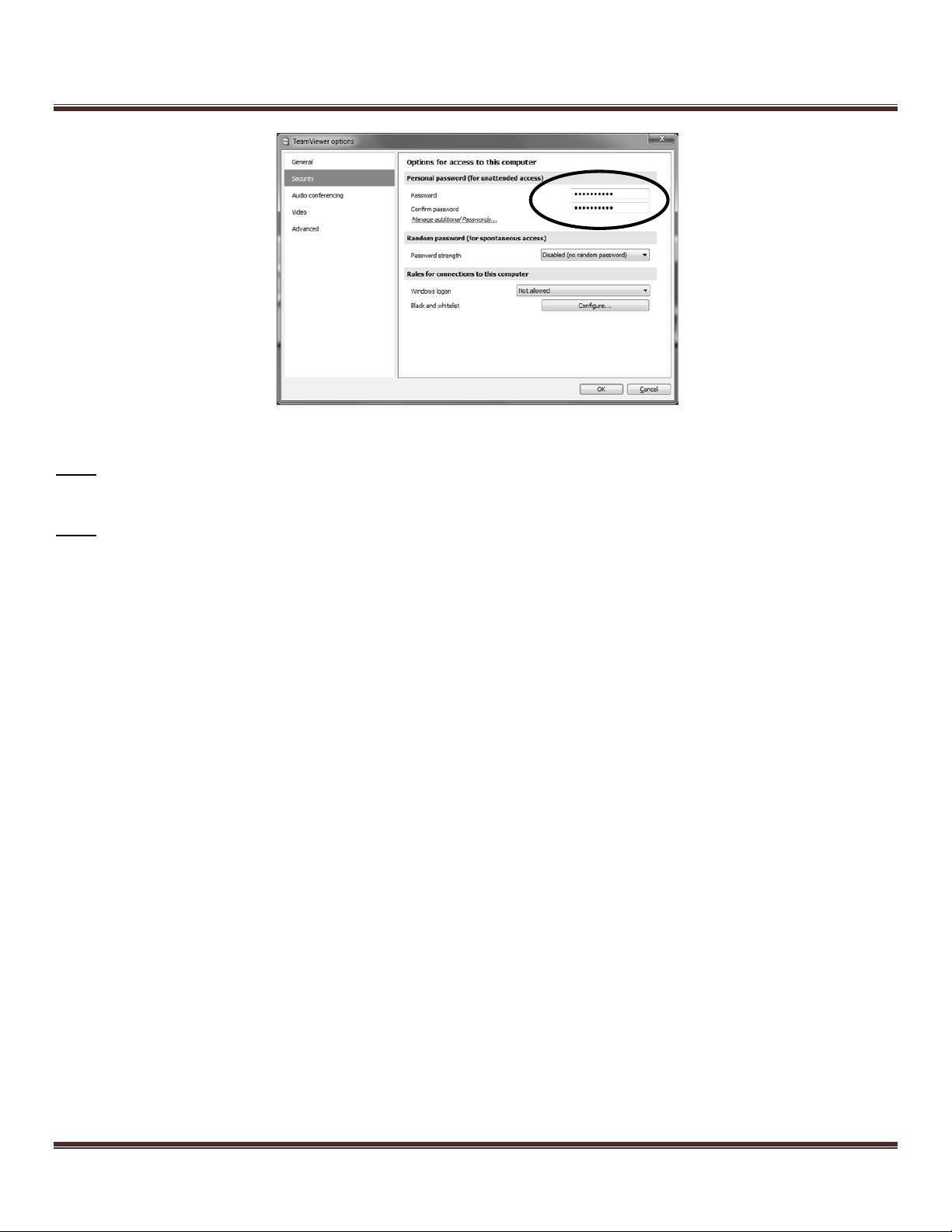
To change your TeamViewer password:
1) Right-click on the blue TeamViewer icon in the system tray and select “Options” (Figure 73).
Figure 73: TeamViewer icon in the system tray
2) Click on the “Security” tab on the right side of the window that pops up. There, you will be able to type in a new
password.
Page 52 Copyright FlyThisSim LLC 2013
FlyThisSim TouchTrainer® Set-up Guide
Figure 74: TeamViewer options window
Note: It is recommended that you write down this password and save it in a secure location, as TeamViewer will need to
be reinstalled if the password is lost.
Note: To view your TeamViewer ID, left-click on the blue TeamViewer icon in the system tray.
Copyright FlyThisSim LLC 2013 Page 53

Computer Specifications
Computer System:
Warranty Period: 1 year
Neway 10.4” Touch Screen monitor
Model #: Fa1046-np/c/t
Warranty Period: 1 year.
Warranty details: http://www.newaymonitor.com/CustomerServices.aspx?Flag=1&TypeID=4
Planar Touchscreen
Warranty Period: 3 years
Model: PXL2430MW 24"
Product details: http://www.planar.com/products/flatpanel_monitors/pxl2430mw/
Warranty details: http://www.planar.com/products/docs/cbu/warranty/planar-3yr-warranty.pdf
Manuals: http://www.planar.com/products/docs/cbu/current_manual/mn-planar-pxl2430mw.pdf
Saitek Cessna Yoke
Product details: http://www.saitek.com/uk/prod/cessnayoke.html
Warranty Period: 2 years.
Warranty details: http://support.madcatz.com/Tickets/Submit/RenderForm
Saitek Pro Flight Throttle Quadrant
Product details: http://www.saitek.com/uk/prod/quad.html
Warranty Period: 2 years.
Warranty details: http://support.madcatz.com/Tickets/Submit/RenderForm
http://www.flythissim.com/pdf_files/Pro Flight Quadrant_QSG.pdf
Saitek Pro Flight Cessna Rudder Pedals
Product details: http://www.saitek.com/uk/prod/cessnapedals.html
Warranty Period: 2 years.
Warranty details: http://support.madcatz.com/Tickets/Submit/RenderForm
http://www.saitek.com/manuals/pro_flight_rudder_pedals_en.pdf
Your TouchTrainer® comes with a high-performance desktop computer to get the most out X-Plane.
MSI 760GM-E51 Motherboard with 8GB RAM
GTX 750 Graphics Card
500W Power Supply
AMD Quad-Core Processor
120GB Solid State Drive
DVD-ROM Drive
Windows 7 64-bit Home Edition with all updates installed
Product Warranties and Online Manuals
Page 54 Copyright FlyThisSim LLC 2013

FlyThisSim TouchTrainer® Set-up Guide
Computer System:
Warranty Period: 1 year
Neway 10.4” Touch Screen monitor Model #: Fa1046-np/c/t.
Warranty Period: 1 year.
Warranty details: http://www.newaymonitor.com/CustomerServices.aspx?Flag=1&TypeID=4
Planar Touchscreen Model: PXL2430MW 24’’.
Warranty Period: 3 years
Product details: http://www.planar.com/products/flatpanel_monitors/pxl2430mw/
Warranty details: http://www.planar.com/media/211099/planar-3yr-warranty.pdf
Manuals: http://www.planar.com/products/docs/cbu/current_manual/mn-planar-pxl2430mw.pdf
Saitek Cessna Yoke
Product details: http://www.saitek.com/uk/prod/cessnayoke.html
Warranty Period: 2 years.
Warranty details: http://support.madcatz.com/Tickets/Submit/RenderForm
Saitek Pro Flight Throttle Quadrant
Product details: http://www.saitek.com/uk/prod/quad.html
Warranty Period: 2 years.
Warranty details: http://support.madcatz.com/Tickets/Submit/RenderForm
http://www.flythissim.com/pdf_files/Pro Flight Quadrant_QSG.pdf
Saitek Pro Flight Cessna Rudder Pedals
Product details: http://www.saitek.com/uk/prod/cessnapedals.html
Warranty Period: 2 years.
Warranty details: http://support.madcatz.com/Tickets/Submit/RenderForm
http://www.saitek.com/manuals/pro_flight_rudder_pedals_en.pdf
Acer S231 LED-Backlight LCD monitor (Slim Design)
Warranty Period: 3 years.
Details: http://us.acer.com/ac/en/US/content/limited-warranty
Computer Specifications for FTS RED
Your TouchTrainer® RED comes with a high-performance desktop computer to get the most out X-Plane.
Intel LGA 1150 Motherboard with 8GB RAM
GTX 750 Graphics Card and GTX 760 Graphics Card
650W Power Supply
Intel Core i5 Quad-Core Processor
120GB Solid State Drive
DVD-ROM Drive
Windows 7 64-bit Home Edition with all updates installed
Product Warranties and Online Manuals
Copyright FlyThisSim LLC 2013 Page 55

Chapter 5: Troubleshooting
Things don’t always go to plan. This section should solve the most common issues encountered by users. On the
desktop, there is a PDF with more detailed instructions. For more complicated problems, feel free to contact FlyThisSim
support.
1. The Yoke, Joystick, or Throttle indicator is RED during SimAVIO startup
a. Check all USB connections to make sure that the cables are connected firmly.
b. Check that all numbered USB cables are plugged into their appropriate ports.
c. Try reinstalling drivers. When hardware is plugged into a USB port, Windows 7 will automatically
download the necessary drivers. Verify that your computer is connected to the internet, then remove
and then reconnect the cables. This will prompt Windows 7 to check for and install available drivers
from the internet.
2. The VISX display is not working correctly
a. On the desktop, right click to bring up the options menu, and select NVIDIA Control Panel:
Figure 75: Options Menu
b. From the NVIDIA control panel menu bar, select “Desktop,” then from “Surround Displays,”
deselect the “Confine Taskbar to Center Display” option, and select the “Maximize Windows Across
All Displays” option.
Figure 76: Configuring the Surround Displays options
Page 56 Copyright FlyThisSim LLC 2013

FlyThisSim TouchTrainer® Set-up Guide
c. If the taskbar is not already locked to the bottom of the main touch monitor, locate the taskbar, right-
click, and deselect the “Lock the Taskbar” option. From there, click and drag the task bar to the
bottom of the main monitor, right click, and reselect the “Lock the Taskbar” option.
Figure 77: Locking the Taskbar
d. From the NVIDIA control panel, select “Configure Surround” and click “Configure.”
Figure 78: Configure Surround Menu
e. From the “What would you like to configure” menu, select the first option, “Displays.”
.
Figure 79: Configure Display for Surround Menu
Copyright FlyThisSim LLC 2013 Page 57

f. From the next menu, select “Connect displays as shown, and click Apply. The screens will
temporarily go dark.
Figure 80: Connect Displays as Shown
As
g. Now, apply the correct configurations as shown and click Next. Note that the numbering for your
monitors may be different—be sure to drag and drop the configurations to match your setup.
Figure 81: Apply Configurations
Page 58 Copyright FlyThisSim LLC 2013

FlyThisSim TouchTrainer® Set-up Guide
h. Next, select the “Yes, add special resolutions” option from the menu.
Figure 82: Bezel Correction Selection
i. Next, type in 110, as shown, in the bezel width adjustment prompts, and click Create Resolutions.
The screen will go dark momentarily.
He The
Figure 83: Bezel Width Adjustment Menu
Copyright FlyThisSim LLC 2013 Page 59

j. Now, return to the NVIDIA control panel as before, and go to “Change Resolution.” From this menu,
select “4983x900 (bezel corrected),” and click Apply. The screen will again flash dark for a moment.
Figure 84: Change Resolution Menu
Page 60 Copyright FlyThisSim LLC 2013

FlyThisSim TouchTrainer® Set-up Guide
k. Finally, go to “Set up multiple displays” in the NVIDIA control panel, and configure the position of
the 1 & 2 (Main and Aux) monitors. The Main monitor should be at position (1550, 900) and the Aux
monitor should be at position (3470, 900).
l. If the Main monitor does not snap into its position when dragged with the mouse, move it so that it
snaps into alignment on the left side of the setup, and use the arrow keys to move it into its position.
The arrow keys move the currently selected monitor in increments of 50, so from the left edge it will
take the main monitor 31 taps to reach its position.
m. When the correct monitor positions are reached, click Apply. The screens will flash one last time, and
the VISX system will be fully reconfigured.
Figure 85: Setting Up Multiple Displays – Arranging the Main Touch Monitor
Copyright FlyThisSim LLC 2013 Page 61

Figure 86: Setting up Multiple Displays - Arranging the Aux Monitor
3. Touch Monitor 2 indicator is RED during SimAVIO startup
a. Right click on your desktop and select Screen Resolution. (Figure 87)
b. If you don’t see two monitors, try the following in order:
i. Check all the connections on your AUX monitor
ii. Press the “Detect” button on the Screen Resolution menu
iii. Press the PC/AV button on the front of the AUX display until source “DVI” is shown
iv. Restart the computer. Windows re-detects attached monitors on startup, so this step
commonly solves monitor issues if all else fails.
c. Click and drag the position of the #2 monitor so it is to the right of the #1 display and the top edge of
monitor 2 is in line with the top edge of monitor 1.
d. Set the Resolution of the #2 display to 1280 x 1024.
Page 62 Copyright FlyThisSim LLC 2013

FlyThisSim TouchTrainer® Set-up Guide
Figure 87: Screen Resolution window
4. Network indicator is RED during SimAVIO startup
a. If using a wired network, check the connection of the Ethernet cable to the back of the computer. If
connecting to a wireless network, verify that the Wi-Fi Adapter (USB Port #6) is securely plugged in.
b. Check your internet connection by opening Internet Explorer and navigating to any webpage. If the
webpage does not load:
i. Go to your computer’s Control Panel, click on Troubleshooting, then click on Network and
Internet.
ii. Go through the steps to troubleshoot internet connectivity issues
Note: A network connection is required for communication between X-Plane and SimAVIO.
Copyright FlyThisSim LLC 2013 Page 63

5. The touch feature on the AUX display is not working
a. Click Start All Programs eGalaxTouch Configure Utility.
b. Under the General Tab, click Monitor Mapping (Figure 88).
Figure 88: eGalaxTouch Configure Utility
c. The MAIN display (1) will show the image in Figure 89
d. . Press the space bar to skip to the next screen.
Figure 89: Main display Monitor Mapping. Press the space bar on this screen
e. The AUX display (2) will show the image in Figure 90. Tap with your finger to map the AUX
display.
Figure 90: Aux Display Monitor Mapping. Tap the screen to map this display
Page 64 Copyright FlyThisSim LLC 2013

FlyThisSim TouchTrainer® Set-up Guide
6. SimAVIO Freezes during startup
a. Press Control-M to bring SimAVIO out of masked mode. Check the SimAVIO title bar to see if it is
connected to X-Plane.
b. If SimAVIO is connected:
i. Reboot the computer and try starting SimAVIO again. If the problem persists, contact
FlyThisSim support.
c. If SimAVIO is not connected:
i. Bring your mouse to the top of the MAIN display so that the X-Plane menu bar appears.
ii. Click on Plugins > Reload Plugins.
iii. After SimAVIO connects properly, press Control-M again to put SimAVIO back into masked
mode.
NOTE: This problem normally occurs when X-Plane tries to load an aircraft that SimAVIO is not
compatible with. To avoid seeing this problem in the future, ensure that you always load aircraft
using the SimAVIO Load Aircraft button located on the AUX monitor.
7. Throttle, Rudder Pedals, and/or Stick/Yoke do not work, or do not work correctly
a. Restart SimAVIO, paying attention to the connection indicators at the top left of the screen. If one of
the indicators turns RED during startup, refer to Troubleshooting items 1-3.
b. If SimAVIO and X-Plane load without error, your equipment may not be assigned or calibrated
correctly.
i. Bring your mouse pointer to the top of the X-Plane window so that the top menu appears.
Click on Settings > Joystick & Equipment.
ii. Move the problematic control over its range of motion (for example, if the throttle is having
problems then move the throttle in and out). Take note of the slider that moves on the screen
and ensure that it is assigned to the correct control.
iii. Use the two buttons on the top of the page, labeled Calibrate Joystick Hardware and Use
THIS position as CENTER to re-calibrate your equipment.
Copyright FlyThisSim LLC 2013 Page 65

8. One or more of the switches, buttons, or keyboard commands do not work
a. Follow the procedure in the beginning of Chapter 3, Configuring X-Plane Settings
9. This instrument panel won’t load
Figure 91: The "Waiting for Connection" screen
a. This screen displays when SimAVIO cannot find the path to the correct aircraft. To fix this, select
File>Open file and select your aircraft type. Refer to Chapter 3 for instructions on selecting an
aircraft.
10. X-Plane Crash
a. Whenever X-Plane crashes and you are prompted with the following error message, select NO:
b. Next, select the settings drop down menu from the X-Plane tabs on the top left of the X-Plane
window, then select Rendering Options:
Page 66 Copyright FlyThisSim LLC 2013

FlyThisSim TouchTrainer® Set-up Guide
c. In the rendering options menu, in the top left, make sure to check the box labeled “run full-screen at
this resolution”:
Copyright FlyThisSim LLC 2013 Page 67

Chapter 6: Documentation
FAA Approval Copy
Page 68 Copyright FlyThisSim LLC 2013

FlyThisSim TouchTrainer® Set-up Guide
Copyright FlyThisSim LLC 2013 Page 69

Page 70 Copyright FlyThisSim LLC 2013

FlyThisSim TouchTrainer® Set-up Guide
Certificate of Title
Included with your TouchTrainer documentation you will find a certificate labelled
“Certificate of Title”, see below:
Figure 92: Certificate of Title Document Format
You may show the included certificate to your aviation insurance provider for possible
discounts on your insurance policy/plan!
Copyright FlyThisSim LLC 2013 Page 71
 Loading...