


USER MANUAL
MiniPOS
Hardware System
VERSION V1.0 AUG 2010

ii
Copyright 2010 August
All Rights Reserved
Manual Version 1.0
Part Number: 3LMPPA530110
The information contained in this document is subject to change without notice.
We make no warranty of any kind with regard to this material, including, but not
limited to, the implied warranties of merchantability and fitness for a particular
purpose. We shall not be liable for errors contained herein or for incidental or
consequential damages in connection with the furnishing, performance, or use of
this material.
This document contains proprietary information that is protected by copyright. All
rights are reserved. No part of this document may be photocopied, reproduced
or translated to another language without the prior written consent of the
manufacturer.
TRADEMARK
Intel®, Pentium® and MMX are registered trademarks of Intel® Corporation.
Microsoft® and Windows® are registered trademarks of Microsoft Corporation.
Other trademarks mentioned herein are the property of their respective owners.

iii
Safety
IMPORTANT SAFETY INSTRUCTIONS
To disconnect the machine from the electrical power supply, turn off the power 1.
switch and remove the power cord plug from the wall socket. The wall socket
must be easily accessible and in close proximity to the machine.
Read these instructions carefully. Save these instructions for future reference.2.
Follow all warnings and instructions marked on the product.3.
Do not use this product near water.4.
Do not place this product on an unstable cart, stand, or table. The product may 5.
fall, causing serious damage to the product.
Slots and openings in the cabinet and the back or bottom are provided for 6.
ventilation to ensure reliable operation of the product and to protect it from
overheating. These openings must not be blocked or covered. The openings
should never be blocked by placing the product on a bed, sofa, rug, or other
similar surface. This product should never be placed near or over a radiator or
heat register or in a built-in installation unless proper ventilation is provided.
This product should be operated from the type of power indicated on the marking 7.
label. If you are not sure of the type of power available, consult your dealer or
local power company.
Do not allow anything to rest on the power cord. Do not locate this product where 8.
persons will walk on the cord.
Never push objects of any kind into this product through cabinet slots as they 9.
may touch dangerous voltage points or short out parts that could result in a re or
electric shock. Never spill liquid of any kind on the product.
CE MARK
This device complies with the requirements of the EEC directive 2004/108/EC
with regard to “Electromagnetic compatibility” and 2006/95/EC “Low Voltage
Directive”.
FCC
This device complies with part 15 of the FCC rules. Operation is subject to the
following two conditions:
(1) This device may not cause harmful interference.
(2) This device must accept any interference received, including interference that
may cause undesired operation.

iv
CAUTION ON LITHIUM BATTERIES
There is a danger of explosion if the battery is replaced incorrectly. Replace only
with the same or equivalent type recommended by the manufacturer. Discard used
batteries according to the manufacturer’s instructions.
LEGISLATION AND WEEE SYMBOL
2002/96/EC Waste Electrical and Electronic Equipment Directive on the treatment,
collection, recycling and disposal of electric and electronic devices and their
components.
The crossed dust bin symbol on the device means that it should not be disposed
of with other household wastes at the end of its working life. Instead, the device
should be taken to the waste collection centers for activation of the treatment,
collection, recycling and disposal procedure.
To prevent possible harm to the environment or human health from uncontrolled
waste disposal, please separate this from other types of wastes and recycle it
responsibly to promote the sustainable reuse of material resources.
Household users should contact either the retailer where they purchased this
product, or their local government office, for details of where and how they can
take this item for environmentally safe recycling.
Business users should contact their supplier and check the terms and conditions of
the purchase contract.
This product should not be mixed with other commercial wastes for disposal.

v
Revision History
Changes to the original user manual are listed below:
Revision Description Date
1.0 Initial release• 2010 August

vi
Table of Contents
1. Packing List .............................. 1
1-1. Standard Items ........................................................1
1-2. Optional Items .........................................................1
2. System View ............................. 2
2-1. Front View ...............................................................2
2-2. Top View ..................................................................2
2-3. Side View .................................................................3
2-4. Rear View ................................................................3
2-5. I/O view ....................................................................4
2-6. Dimensions & View Angles ......................................5
3. System Assembly .................... 6
3-1. Display Tilt Angle Adjustment ..................................6
3-2. Open the Cable Cover .............................................7
3-3. RAM Module Replacement ......................................8
3-4. HDD Replacement ...................................................9
3-5. Power Adapter Installation ......................................10
4. Peripheral Installation ............ 11
4-1. WLAN Installation ................................................... 11
5. Specication ........................... 12

vii
6. Jumper Setting ........................ 13
6-1. Motherboard Layout ...............................................13
6-2. Connectors & Functions .........................................14
6-3. Jumper Setting .......................................................15
Appendix: Drivers Installation .... 18

1
Packing List1.
Standard Items
1-1.
Note: Power cord will be supplied differently according to
various region or country.
Optional Items
1-2.
g. WLAN card
a. System d. Power adapter
b. Driver bank e. Power cord
c. User guide f. RJ45-DB9 cable (x2)

2
System View2.
Front View
2-1.
Touch Screen
USB
Power Button
Top View
2-2.
Power LED
HDD Indicator
iButton
MSR
Keyboard

3
Side View
2-3.
Ventilation
MSR
Speaker
Cable Blind Hole
VFD
Cable Cover
Rear View
2-4.

4
I/O view
2-5.
a
b
c
d
e
f
g
hhi
j
Item No. Description
a DC-IN 19V
b DC-OUT 24V
c Cash Drawer
d LAN
e USB
f COM1, 2, 3, 4
g PS/2
h Screws for xing the keyboard
i 2nd VGA
j Parallel

5
Dimensions & View Angles
2-6.
224mm
336.5mm
227mm
251mm
267mm
45°
60°
75°

6
System Assembly3.
Display Tilt Angle Adjustment
3-1.
Take apart the rubber hinge covers 1.
(x2) at both sides.
Loose screws (x2) inside for adjust-2.
ment.
Default
5. The display viewing angle can be
adjusted (total 3 adjustable).
*Note: Default 45 degrees.
3. Take apart the rubber hinge covers
(x2) near the ventilation holes.
4. Remove screws (x2) inside to adjust
display tilt angle.
7
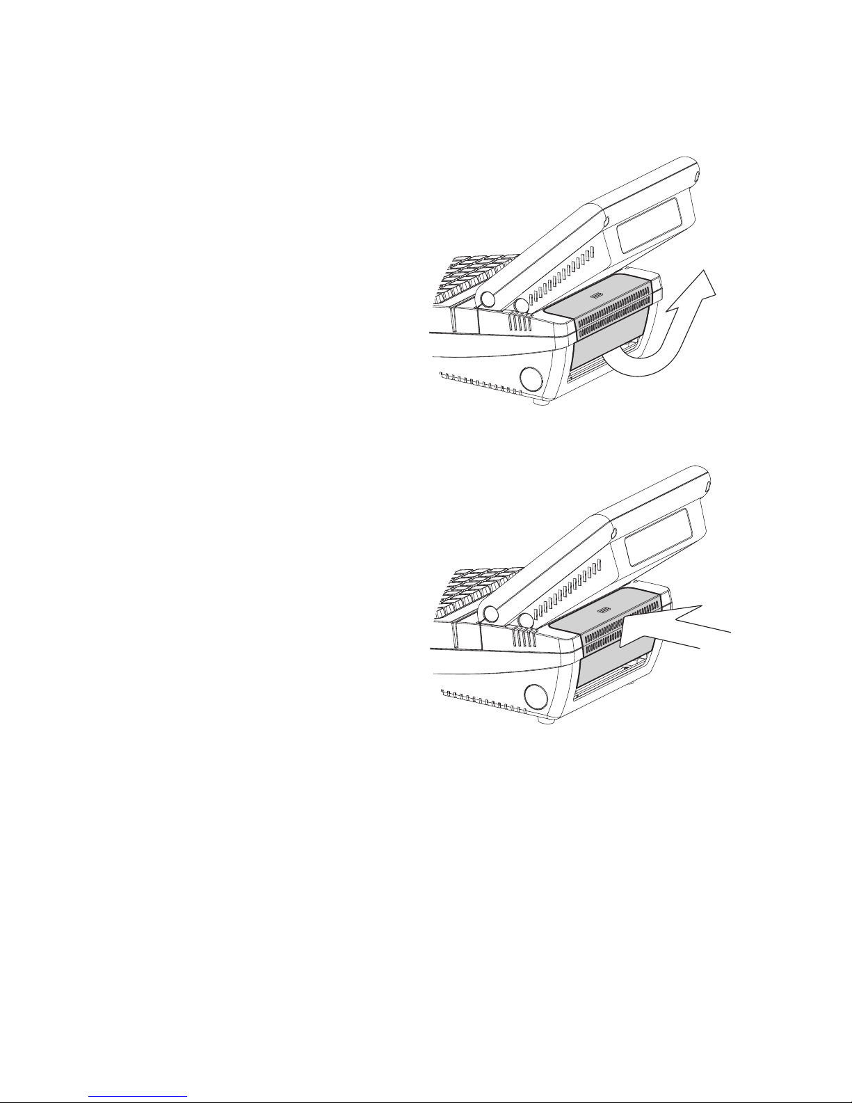
Open the Cable Cover
3-2.
Turn to the rear side of the sytem.1.
Open the cable cover by lifting upward 2.
(as arrow shown).
To put it back, do parallely push the 3.
cable cover untill you hear clicking
sound.

8
RAM Module Replacement
3-3.
Slide and open the keyboard.3.
Removing a RAM module
Find the memory slow at the left 4.
inside of the motherboard.
Before Replacement
Follow the steps at 3-2 to open the 1.
cable cover at the back.
Remove screws (x2) on upper side of 2.
the I/O panel.
Flip the ejector clips outwards to 5.
remove the memory module from the
memory slot.
Installing a RAM moudle
Slide the memory module into the 6.
memory slot and press down until the
ejector clips click in place.

9
HDD Replacement
3-4.
Uninstall the HDD holding bracket.4.
To remove and replace the HDD, please follow the steps below.
Follow the steps at 3-2 to open the 1.
cable cover at the back.
Loose the screw (x1) on HDD 2.
holding bracket.
Pull the screw to slide bracket out 3.
of the system.
Slide to remove HDD from the 5.
system and disconnect the HDD
cable.
Reverse Step 5 to replace the 6.
hard drive disk.
As for installation, after connecting 7.
HDD to the system, slide the
bracket reversely, engaging the
alignment pin. Finally fasten
the screw(x1) to complete
replacement.
10
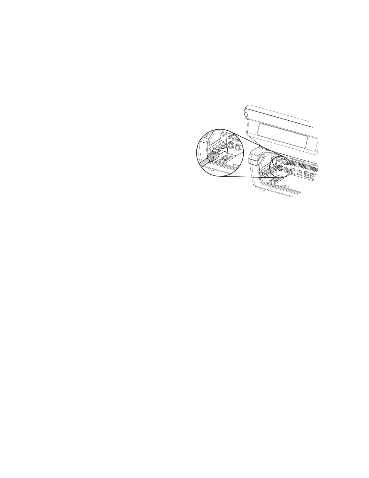
Follow the steps at 3-2 to open the 1.
cable cover at the back.
Find the power connector on the 2.
left side of the I/O panel.(refer to
2-5 a. )
Please connect the power adapter 3.
directly to the DC-IN Connector.
Power Adapter Installation
3-5.
The system is equipped with a 90W power adapter. Please plug it into the
system as shown below.

11
Peripheral Installation4.
WLAN Installation
4-1.
Follow the steps of “Before Re-1.
placement” at 3-3 to open the
system.
Find the PCI-E WLAN card at 2.
the right side of the motherboard.
There are 2 wires installed with-3.
in the system: black and grey.
Connect the black wire to Main
connector while connect the
grey to Aux. connector on the
card.
Aux:Grey
Main:Black
Insert the WLAN card into the 4.
slot.
Fasten the screw (x1) onto the 5.
Main side to fix the WLAN card.
*Note: The WLAN antenna and
wires will be pre-installed prior
to shipping if the function requested.

12
Motherboard C35 V0.9B
Processor Intel® Atom N270 processor 1.6GHz L2 512K FSB 533MHz
Chipset Intel® 945GSE Express + ICH7M
System Memory 1 x DDR2 DIMM up to 2GB
Graphic Memory Share System Memory up to 232MB
Storage Device
Hard Drive 1 x 2.5" HDD 160G (SATA interface)
LCD/Touch Panel
Size 8.4"
Brightness 250 cd/m²
Resolution 800 x 600
Touch Type 8.4” Resistive
System I/O Ports
PS2 1
USB 2.0 4 (2 front+2 rear)
Serial/COM 4 RJ45 COM (COM3/COM4 with 5V/12V power)
Parallel 1
LAN 1 x RJ-45 (10/100/1000Mbps Giga LAN)
2nd VGA 1 x female type connector with power
DC-IN 19V 1
DC-OUT 24V 1 (Receipt printer)
Cash Drawer 1 x RJ11 (12V/24V)
Power Button 1
Audio
Internal Speaker 2W x 2
Power Adapter (19V / 90W)
Programmable Keyboard
60 Keys (PS2)
Wireless (optional)
Mini PCI-e WLAN card IEEE 802.11 b/g/n
Main Modules MSR iButton (optional) VFD (optional)
Component Type 3 tracks DALLAS 2X20
Environment
EMC & Safety FCC / CE Class A, LVD
Operating Temperature 5°C ~ 35°C (41°F ~ 95°F)
Storage Temperature -10°C ~ 60°C (14°F ~ 140°F)
Dimension (W x D x H) 224 x 300x 238 (mm)
Weight
N. W. (kgs) 3.4
G. W. (kgs) 5.4
Specication5.
* This specication is subject to change without prior notice.

13
Version: C35 v0.9B
200
DDR2_A1
FAN-SYS3
BAT1
CN21
SW3
CN15
CN28
CN29
CN25
SKT3
CN4
SAT A2
SAT A1
CN6 CN5
CN3
JP5
JP3
JP6
CN24
CN14 CN10
CN16
CN13
CN27
MINI_PCIE3
JP4
CN7
CN12
JP9 JP10
JP11
CN30
CN31
CN22
CN9
JP8
PS1
RJ45_4
USB3
RJ45_3
RJ11_3
PWR4
PWR3
JP3
JP4
JP5
JP6
JP7
JP8
JP10
JP9
Jumper Setting6.
Motherboard Layout
6-1.

14
Connector Purpose
CN3 Audio Line Out
CN4 / CN25 Power Connector for HDD
CN5 / CN6 USB Connector
CN7 LAN LED Connector
CN9 MSR Connector
CN10 / CN14 T-CON Connector
CN12 IrDA Connector
CN13 Inverter Connector
CN15 Power LED Connector
CN21 Internal Power Switch Connector
CN24 System Diagnostic Board Connector
CN27 LPT Port
CN28 HDD LED Connector
CN29 Front I/O Board Connector
CN30 Program Key Board Connector
CN31 4 Wire Touch
DDR2_A1 DDR2 SO-DIMM
FAN_SYS3 System FAN Connector
MINI_PCIE3 Mini PCI-E Socket
SW3 Power Button
PWR3 +19V Power Adapter
PWR4 +24V Power Adapter for Thermal Printer
RJ11_3 Cash Drawer Connector
RJ45_3 LAN Port
RJ45_4 COM1, COM2, COM3, COM4
PS1 PS2 Connector
SATA1 SATA Connector
SATA2 SATA Connector
JP3 LCD ID Setting
JP4 Cash Drawer Power Setting
JP5 AT/ATX Setting
JP6 CMOS Operation Mode
JP7 System Reset
JP8 COM3 & COM4 Power Setting
JP9 / JP10 VGA Port Connector
Motherboard Version: C35 v0.9B
Connectors & Functions
6-2.

15
Jumper Setting
6-3.
System Reset6-3-1.
Function JP7 (1-2)
▲Normal
2
1
Reset
2
1
COM3 & COM4 Power Setting6-3-2.
Function JP8
COM3 Pin10
▲RI
5 7 9 11
2
1 3
6 8 10 124
+5V
11
128 10
5 7 9
2
1 3
64
+12V
11
128 10
5 7 9
2
1 3
64
COM4 Pin10
▲RI
11
128 10
5 7 9
2
1 3
64
+5V
11
128 10
5 7 9
2
1 3
64
+12V
11
128 10
5 7 9
2
1 3
64
▲ = Manufacturer Default Setting

16
Cash Drawer Power Setting6-3-3.
Function JP4
+12V
2
1 3
4
▲+19V
2
1 3
4
Power Mode Setting6-3-4.
Function JP5
▲ATX Power
2
1
AT Power
2
1
CMOS Operation Mode6-3-5.
Function JP6 (1-2)
▲Normal
2
1
Reset
2
1
▲ = Manufacturer Default Setting

17
LCD ID Setting6-3-6.
Panel# Resolution
LVDS
Output
Interface
JP3
Bits Channel
1 1366 x 768 24 Single LVDS
8
5 7
2
1 3
64
2 1440 x 990 24 Dual LVDS
8
5 7
2
1 3
64
4 1920 x 1080 24 Dual LVDS
1 587
2
3
64
5 1024 x 768 24 Single LVDS
8
5 7
2
1 3
64
6 1280 x 1024 24 Dual LVDS
8
5 7
2
1 3
64
7 800 x 600 24 Single LVDS
8
5 7
2
1 3
64
9
1024 x 768
18
Single
LVDS
8
5 7
2
1 3
64
11 800 x 600 18 Single LVDS
8
5 7
2
1 3
64
12 800 x 600 18 Single LVDS
8
5 7
2
1 3
64
14
▲
800 x 600 TTL
8
5 7
2
1 3
64
15 1024 x 768 TTL
8
5 7
2
1 3
64
CRT
8
5 7
2
1 3
64
Remark: Item #12 is only applied for Sharp panel 12" LQ121S1LLG41.
2
1
Jumper open
2
1
Jumper short
▲ = Manufacturer Default Setting

18
Appendix: Drivers Installation
The shipping package includes a Driver CD in which you can nd every individual
driver and utility that enables you to install the drivers on the system.
Please insert the Driver CD into the drive and double click on the “index.htm” to
select the models. You can refer to the drivers installation guide for each driver in
the “Driver/Manual List”.
 Loading...