

Page 1
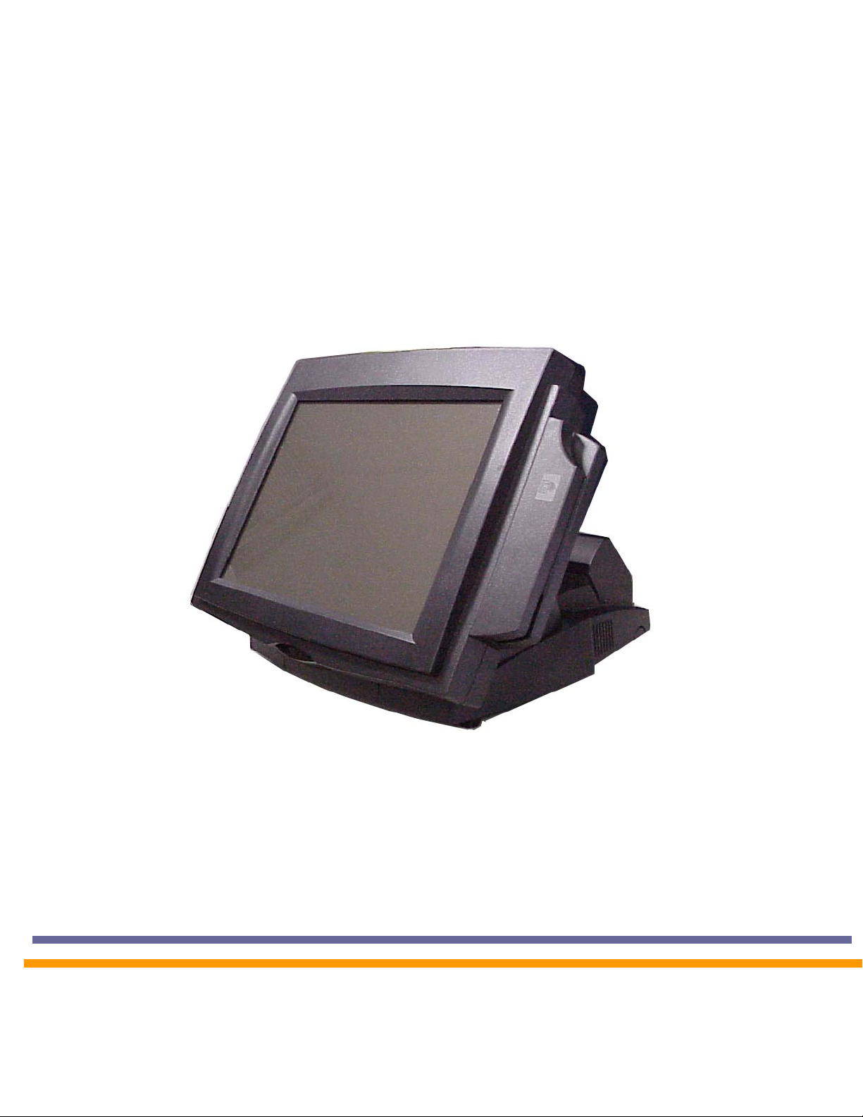
POS500/505
with B55/B65 M/B
Installation Guide
Part No:48200014
January 2004 (V2.1)
Point-of-Sale
Hardware System
Page 2

Safety
IMPORTANT SAFETY INSTRUCTIONS
1. Read these instructions carefully. Save these instructions for future reference.
2. Follow all warnings and instructions marked on the product.
3. Do not use this product near water.
4. Do not place this product on an unstable cart, stand, or table. The product may fall,
causing serious damage to the product.
5. Slots and openings in the cabinet and the back or bottom are provided for ventilation; to
ensure reliable operation of the product and to protect it from overheating, these
openings must not be blocked or covered. The openings should never be blocked by
placing the product on a bed, sofa, rug, or other similar surface. This product should
never be placed near or over a radiator or heat register, or in a built-in installation unless
proper ventilation is provided.
6. This product should be ope rated from the type of po wer in dica ted on th e mark ing l abel.
If you are not sure of the type of power available, consult your dealer or local power
company.
7. Do not allow anything to rest on the power cord. Do not locate this product where
persons will walk on the cord.
8. Never push objects of any kind into this product through cabinet slots as they may touch
dangerous voltage points or short out parts that could result in a fire or electric shock.
Never spill liquid of any kind on the product.
FCC
This device complies with part 15 of the FCC rules. Operation is subject to the following two
condition: (1)This device may not cause harmful interference and (2) This device must
accept any interference received, including interference that may cause undesired
operation.
Caution on Lithium Batteries
Danger of explosion if battery is incorrectly replaced. Replace only with the same or
equivalent type recommended by the manufacturer. Discard used batteries according to
the manufacturer’s instructions.
3
Page 3

Index
Safety.............................................................................................................. 3
1.Accessory .................................................................................................... 5
2.I/O Function ................................................................................................. 7
2.1Front View............................................................................................ 7
2.2I/O port................................................................................................. 7
3.Specification................................................................................................. 8
3.1System Memory Combination.............................................................. 9
4.Peripherals Installation................................................................................. 9
4.1Install External FDD............................................................................. 9
4.2 Install External IDE Device ................................................................11
4.3 Install MCR Module (Optional)...........................................................11
4.4 Install Pole Display Module (Optional).............................................. 12
4.5 Install a Compact Flash Card............................................................ 13
4.6 Install Cash Drawer........................................................................... 13
4.7 Install Second display (Differential of connector board).................... 15
5. Driver Installation...................................................................................... 18
5.1 Netmos ............................................................................................. 18
5.2 Elo_Touch......................................................................................... 19
5.3 LAN-driver......................................................................................... 21
5.4 VGA.................................................................................................. 22
6. Jumper Setting.......................................................................................... 24
6.1 B65(POS500) Jumpers and DIP Switches Locations....................... 24
6.2 B55(POS500/505) Jumpers.............................................................. 28
7.B55 I/O Board Jumper Setting................................................................... 29
7.1 Pin1/Pin9 Function of COM Port Selection: JP1............................ 29
7.2 Cash Drawer Power Selection: JP2............................................... 29
4
Page 4
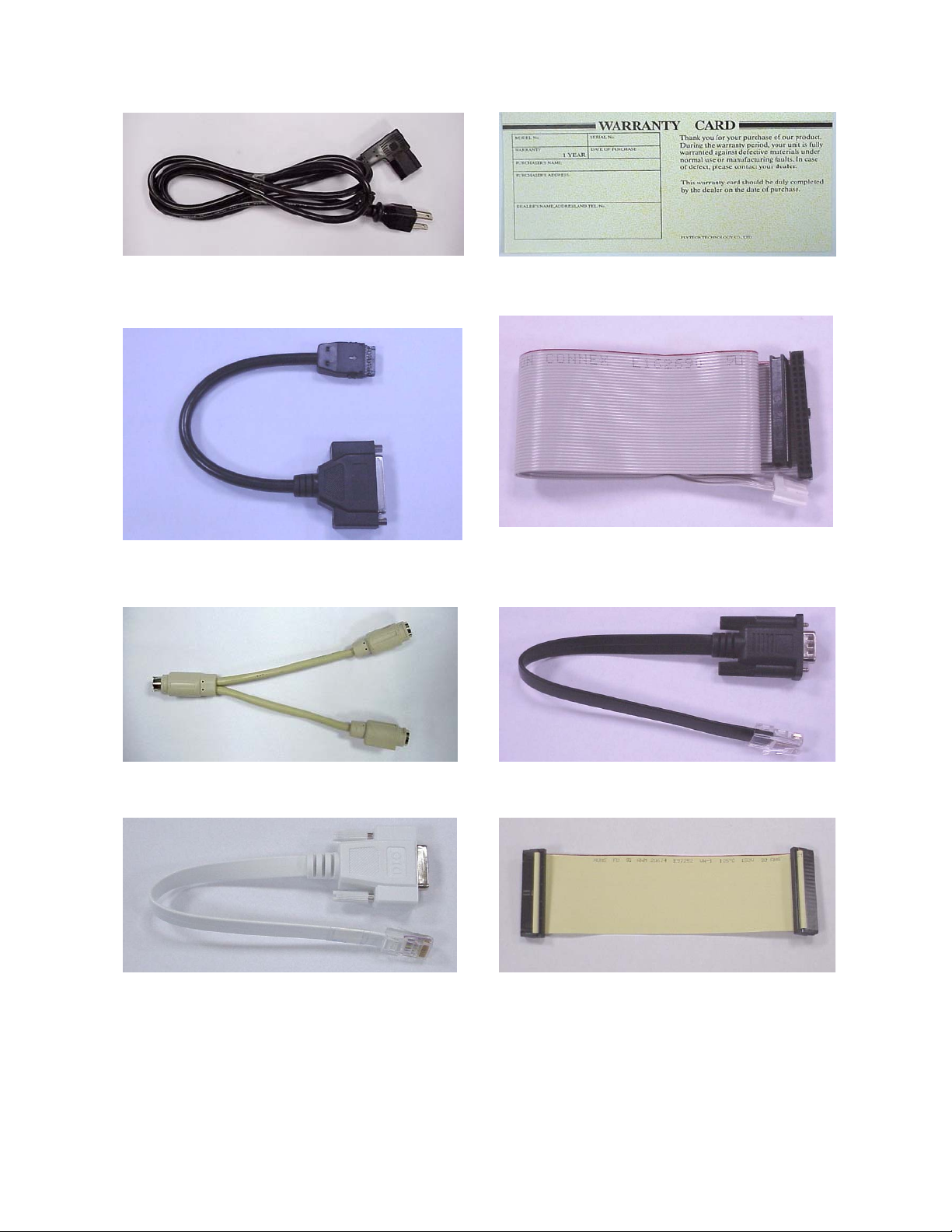
1.Accessory
Power Cord Warranty Card
Printer Cable FDD Cable
Y Cable (Keyboard & Mouse) Serial Cable
DIO Cable External IDE Cable
5
Page 5
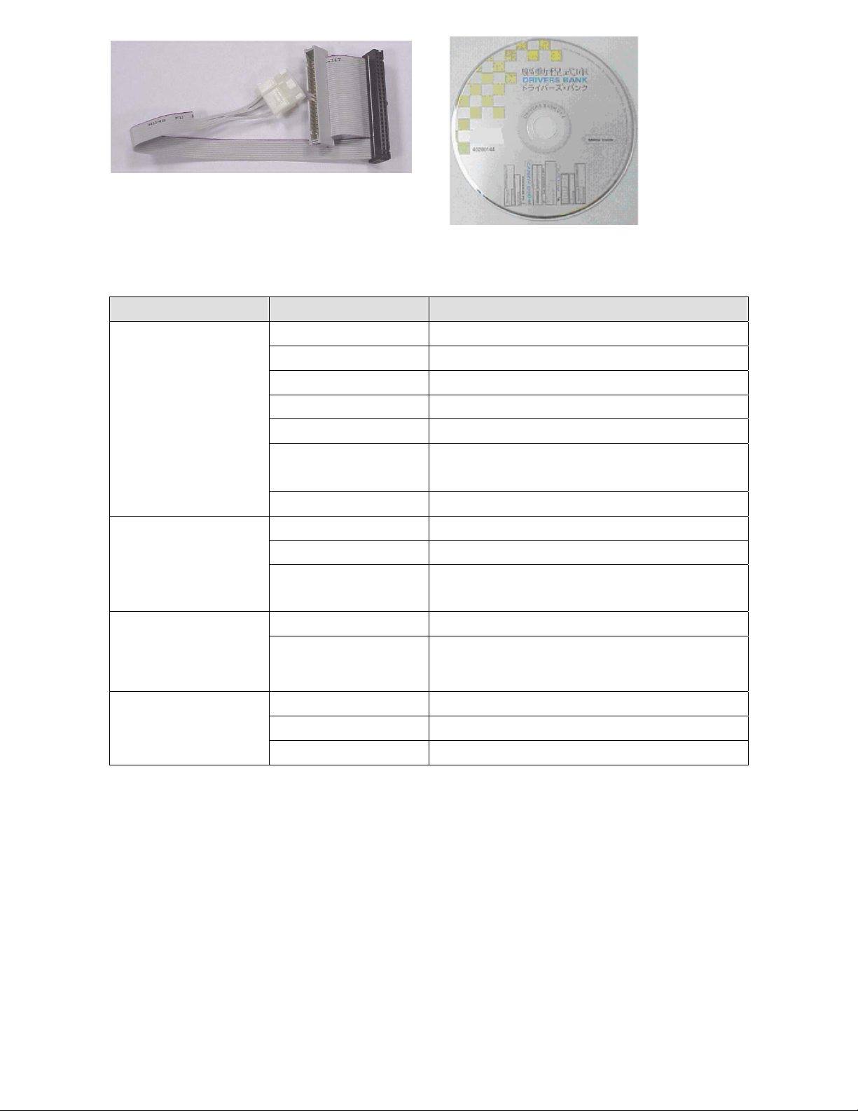
External IDE Cable Drivers Bank
The following drivers in the folders of Driver Bank are necessary for driver installation:
Folder Driver Function
Acrobat Acrobat Reader Installation
BIOS Tool BIOS Update Tool
Common
CDROMDrv CDROM driver installation (for DOS)
Elo_Touch Touch screen driver Installation
LAN_drive LAN driver installation
*Netmos
Enable COM5/COM6
Smart Card Smart Card driver installation
Audio Audio driver Installation
B55
UDMA UDMA driver installation
VGA VGA driver installation
(POS500/505)
Doc2000 Doc2000 driver installation
B65
VGA_69000 VGA driver installation
(POS500)
Card Reader Card Reader Test Program
Test Utility
Cash Drawer Cash Drawer Test Program
VFD Customer Display Test Program
* When using B55 Mainboard, the Touchscreen was set on COM5. The Netmos driver
must be loaded to enable COM5 & COM6 before installing ELO touch driver to COM5.
6
Page 6
2.I/O Function
1
4
1
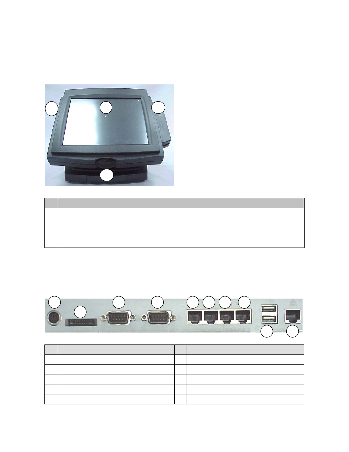
2.1Front View
4
# Function
1 LCD Touch Module
2 Power Switch & External IDE Connector
3 Card Reader
4 External FDD Connector & Compact Flash Socket
2
3
2.2I/O port
2
# Function # Function
1 KB / Mouse 6 COM4
2 LPT 7 COM6
3 COM1 8 Cash Drawer
4 COM2(optional 2nd VGA port) 9 USB1&2
5 COM3 10 LAN
3
7
5
7
8 6
9
10
Page 7
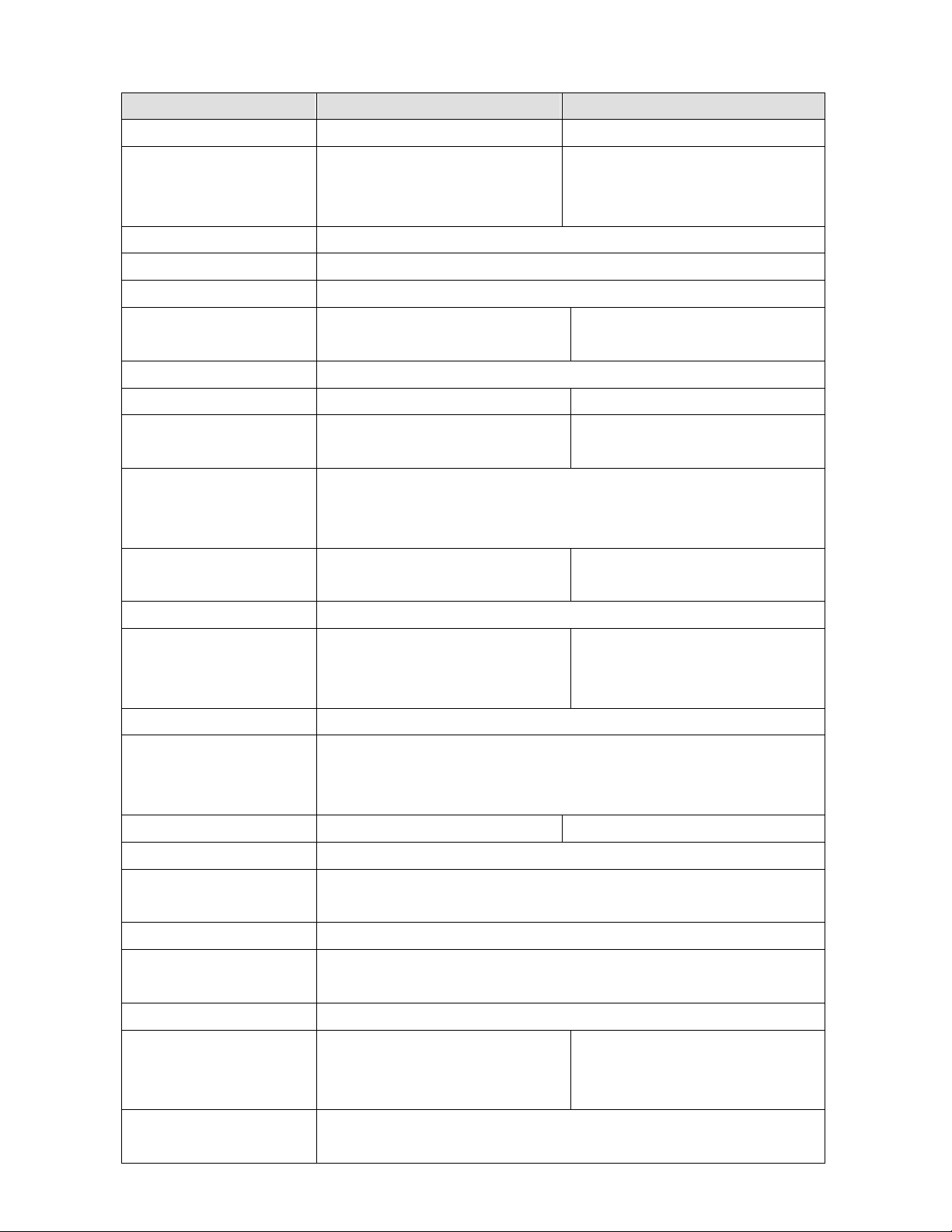
3.Specification
Item POS500 POS500/505
Main Board B65 B55
CPU Supports SK 370
Celeron / PIII
FSB 66/100Mhz
Support s SK 370
Celeron / PIII
FSB 66/100/133Mhz
Co-processor Built-in CPU
Internal Cache Built-in CPU
External Cache Built-in CPU
System Memory 2 x 168pin DIMM socket,
support up to 512 MB
2 x 168pin DIMM socket,
support up to 1GB
BIOS Award PnP BIOS
Core Logic Intel FW82443BX SiS 630ST Single Chip
VGA Display C&T69000 Chip
2MB RAM on chip
LCD Panel POS500 12.1” TFT 800x600 180 cd/m
POS505 15” TFT 1024x768 250 cd/m
Viewing angle 0
~60
o
o
IDE Controller PCI IDE supports ATA
PIO/UDMA33
Built-in SiS630ST
SMA 8M/16M/32M/64MB
2
Touch resistive type
2
Touch resistive type
PCI IDE supports ATA
PIO/UDMA33/66/100
Hard Disk Drive One 3.5” HDD drive by Primary IDE (HDD option)
I/O controller SMSC37C602 support one
40-pin
Built-in Core Logic SiS 630ST
W83697HF / W83697HF
NetMos PCI 9835 x1
FDD controller 40-pin 2.54mm pitch pin-header with power
I/O Port DB-9M COM x 2 (COM1&2) ,10-pin RJ-45 COM x 3 (COM3/4/6)
(COM5 default for Touch Screen),RJ-45 LAN x 1, RJ-45 Cash
Drawer x 1, USB x 2
LAN port Intel 82559ER LAN Chip RTL8139C
ROM disk DiskOnChip Socket supported
Card Reader Keyboard/Serial (3-Track) types supported (20pin)
Can also bundle Barcode Card Reader & Magnetic Card Reader
Compact Flash Type 1 Compact Flash Socket Supported
Customer Display
Options Fix type customer display supports LED/VFD/LCD type
Pole display supports LED/VFD/LCD type
Second display Optional 8.4”/10.4”/12.1” TFT LCD display
Power Supply FT8007 Int. AT 75W
FT8150 Int. ATX 150W
Factory optional FT8150 Int.
ATX 150W
Operation Temperature
5℃~ 35℃
8
Page 8
EMI/EMS CE (Class-A)
System
Dimension(WxDxH)
System Weight (Net) 7.5 Kgs. (16.5 Lbs.)
Note: The control Chip of B55 (Netmos NM9835)/B65(IMP16C552)of COM5 & COM6 is
PCI 2.1 protocol which not support system standby mode.
POS500 12.1” 33 x 32 x 24cm
POS505 15” 37.9x34.5~36.1x20.1~31.2cm
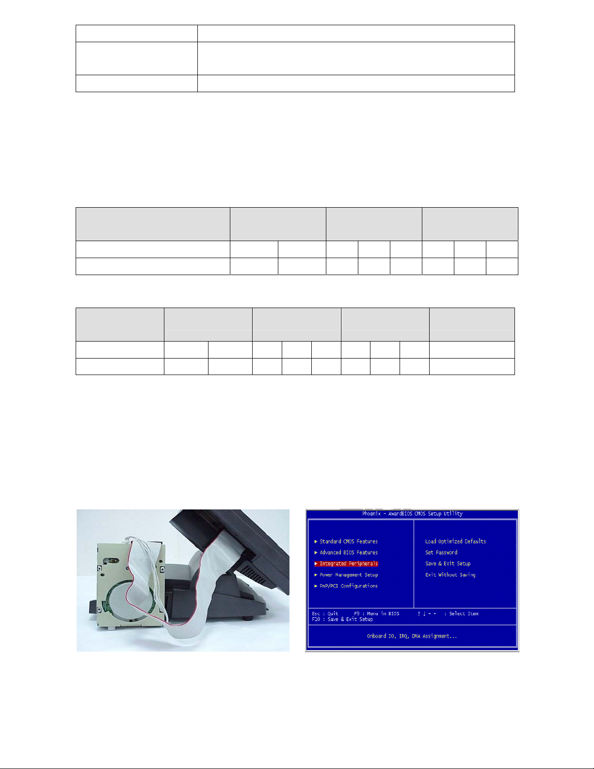
3.1System Memory Combination
B65(POS500)
RAM Size
Slot
DIMM1 X 128 128 256 X 256 512 X
DIMM2 128 X 128 X 256 256 X 512
B55(POS500/505)
RAM Size
Slot
128MB 256MB 512MB 1024MB
128MB 256MB 512MB
DIMM1 X 128 128 256 X 256 512 X 512
DIMM2 128 X 128 X 256 256 X 512 512
Note: Please note that DIMM1 of POS500 does not support RAM over 29 mm in height.
4.Peripherals Installation
4.1Install External FDD
a. Connect the FDD cable from 40 pin FDD
connector left side of LCD module..
b. Enter "Integrated Peripherals" of the Main
Menu of BIOS CMOS Setup Utility.
9
Page 9
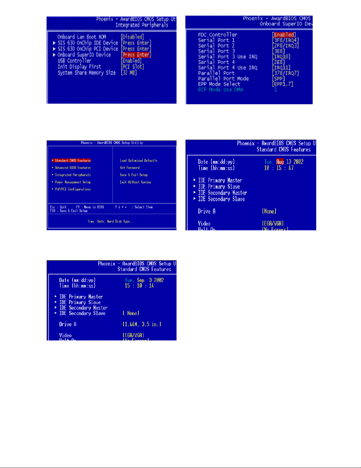
c.Move the arrow key downward to the
"Onboard Super IO Device" item
e. Enter "Standard CMOS Features" of the
Main Menu of BIOS CMOS Setup Utility.
d. Move the arrow key downward to the
"FDC Controller" item. Use "Page Up" or
"Page Down" key change to “Enable”
f. Move the arrow key downward to the
"Drive A" item.
g. Use "Page Up" or "Page Down" key for
FDD Installation. Make sure you save the
changes by pressing F10 key or moving
to "Save & Exit Setup."
10
Page 10
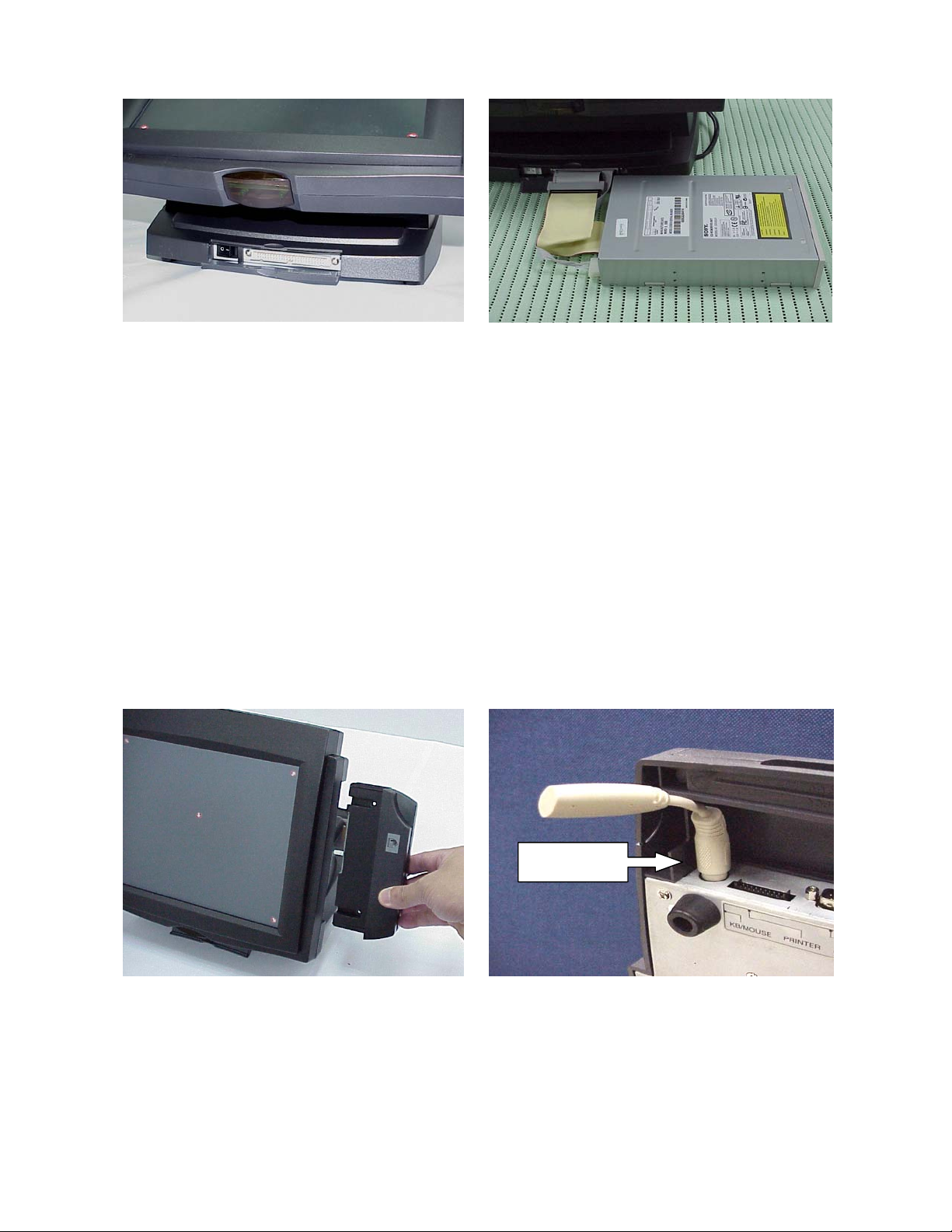
4.2 Install External IDE Device
a. Take out the manufacturer’s IDE cable
provided in the accessory bag, connect
the second HDD or CD-ROM drive to the
50-pin Header as hidden in the Front
Cover of the Base Stand.
b. Connect the IDE cable from either the
second HDD or CD-ROM drive to the 50
pin Header hidden in the Front Cover of
the Base Stand.
4.3 Install MCR Module (Optional)
The optional MCR (Magnetic Card Reader) unit is tested and can be supplied at your
request. This MCR is removed during transportation and can be connected by the user.
The manufacturer offers two types of MCR Module, either by the Serial type or keyboard
type.
Terminator
a. Install the MCR module to the right side of
System Bay Module and lock it with two
screws.
Note: We have a new version that enhances the Keyboard type MCR. When you select a
keyboard type MCR, does not connect a standard P/S2 keyboard or insert the Terminator.
b. If you select a keyboard type MCR and
the system does not connect a standard
P/S2 keyboard, please insert the
Terminator for simulate and instead of the
P/S2 Keyboard.
11
Page 11
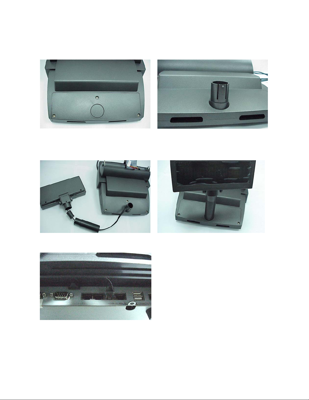
4.4 Install Pole Display Module (Optional)
The POS system is equipped with an interface for a connection to a Pole Display Module.
Please refer to COM6 of CN7 of jumper setting section.
a. Remove Pole Display cover from POS
system unit by f in g er s .
c. Install Pole Display flat cable inside Pole Display Tube. Use either two or one tube.
b. Install Pole Display cover kit onto POS
system unit.
d. Connect Pole Display cable RJ-45
connector to COM6 of POS system.
12
Page 12
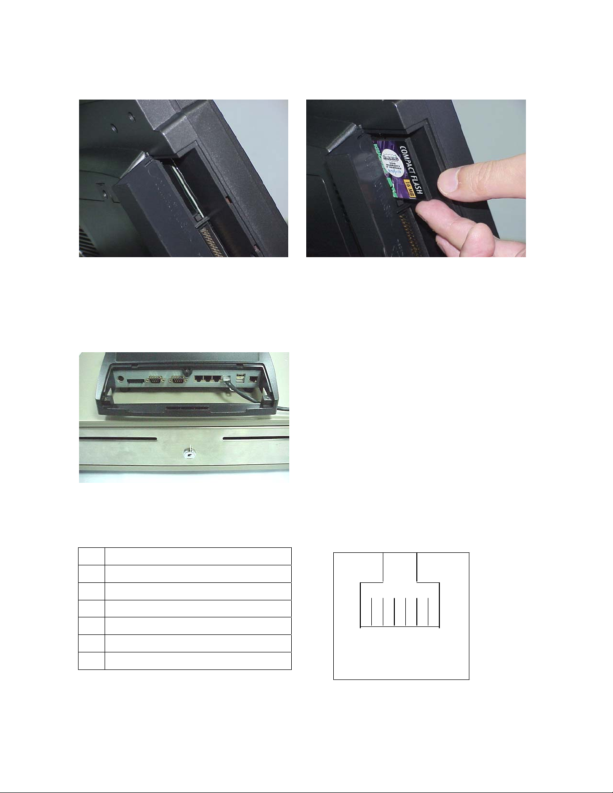
4.5 Install a Compact Flash Card
You can install a compact flash card At the left side of the LCD panel.
4.6 Install Cash Drawer
You can install a cash drawer through the Cash Drawer port.
4.6.1 Cash Drawer Pin Assignment
Pin Signal
1 GND
2 DOUT bit0
3 DIN bit0
4 12V/24V
5 DOUT bit1
6 GND
13
6 1
Page 13
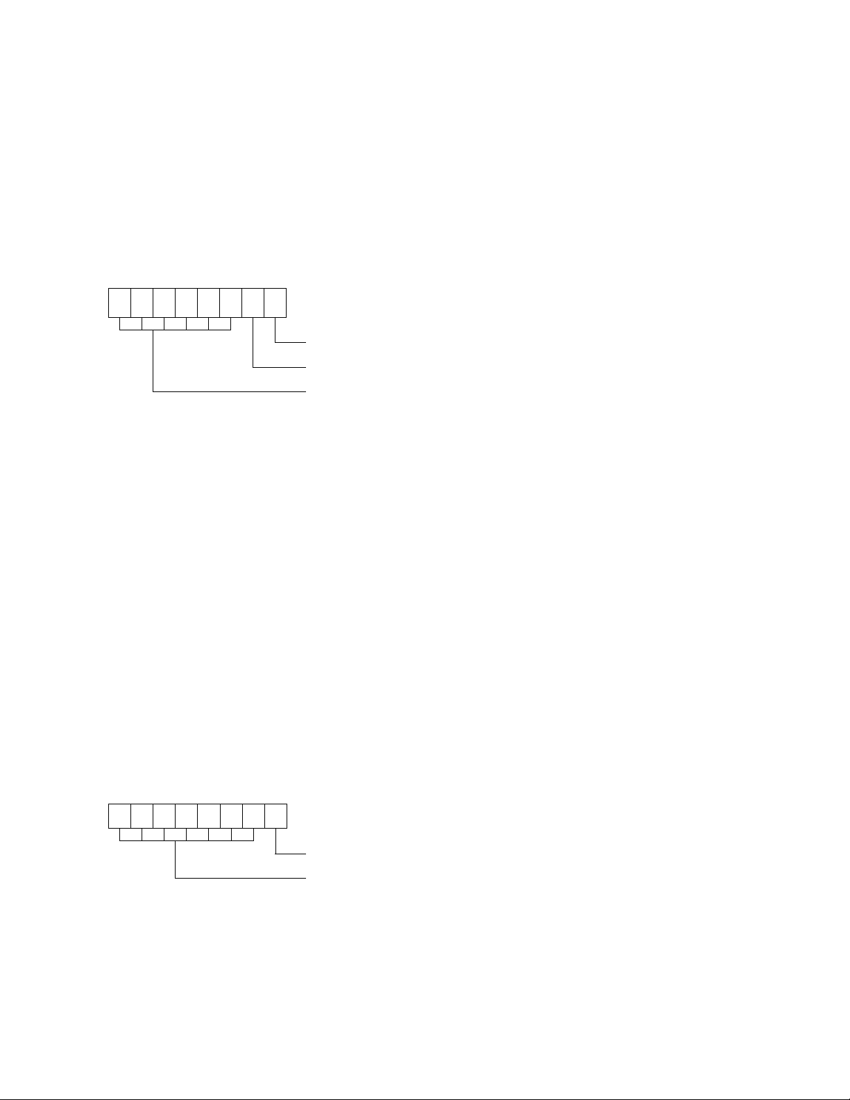
4.6.2 Cash Drawer Controller register
The Cash Drawer Controller use two I/O addresses to control Cash Drawer –Cash Drawer
Control Register and Cash Drawer S tatus Register.
4.6.2.1 Cash Drawer Control Register
Register Location: 200h
Attribute: Write
Size: 8bit
7 6 5 4 3 2 1 0
X X X X X X
Bit 7-2: Reserved
Bit 1: Cash Drawer “DOUT bit1” pin output control.
= 1: Opening the Cash Drawer
= 0: Allow close the Cash Drawer
Bit 0: Cash Drawer “DOUT bit0” pin output control.
= 1: Opening the Cash Drawer
= 0: Allow close the Cash Drawer
Note: Please follow the Cash Drawer control signal design to control the C ash Drawer.
Suggest control the bit1/0 at the same time.
Cash Drawer “DOUT bit0” pin output control
Cash Drawer “DOUT bit1” pin output control
Reserved
4.6.2.2 Cash Drawer Status Register
Register Location: 201h
Attribute: Read
Size: 8bit
7 6 5 4 3 2 1 0
X X X X X X X
Cash Drawer “DIN bit0” pin input status
Reserved
Bit 7-1: Reserved
Bit 0: Cash Drawer “DIN bit0” pin input status.
= 1: the Cash Drawer opened or not exists.
= 0: the Cash Drawer closed.
14
Page 14

4.6.3 Cash Drawer control command example
Use Debug.EXE program under DOS or Windows98
Command Cash Drawer
O 200 01 Opening
O 200 00 Allow to close
¾ Set the I/O address 200h bit0 =1 for opening Cash Drawer by “DOUT bit0” pin control.
¾ Set the I/O address 200h bit0 = 0 for allow close Cash Drawer.
Command Cash Drawer
I 201 Check status
¾ The I/O address 201h bit0 =1 mean the Cash Drawer is opened or not exist.
¾ The I/O address 201h bit0 =0 mean the Cash Drawer is closed.
4.7 Install Second display (Differential of connector board)
a. St andard connector board.
b. Second display connector board.
c. Second display VGA cable 1
A
B
15
Page 15
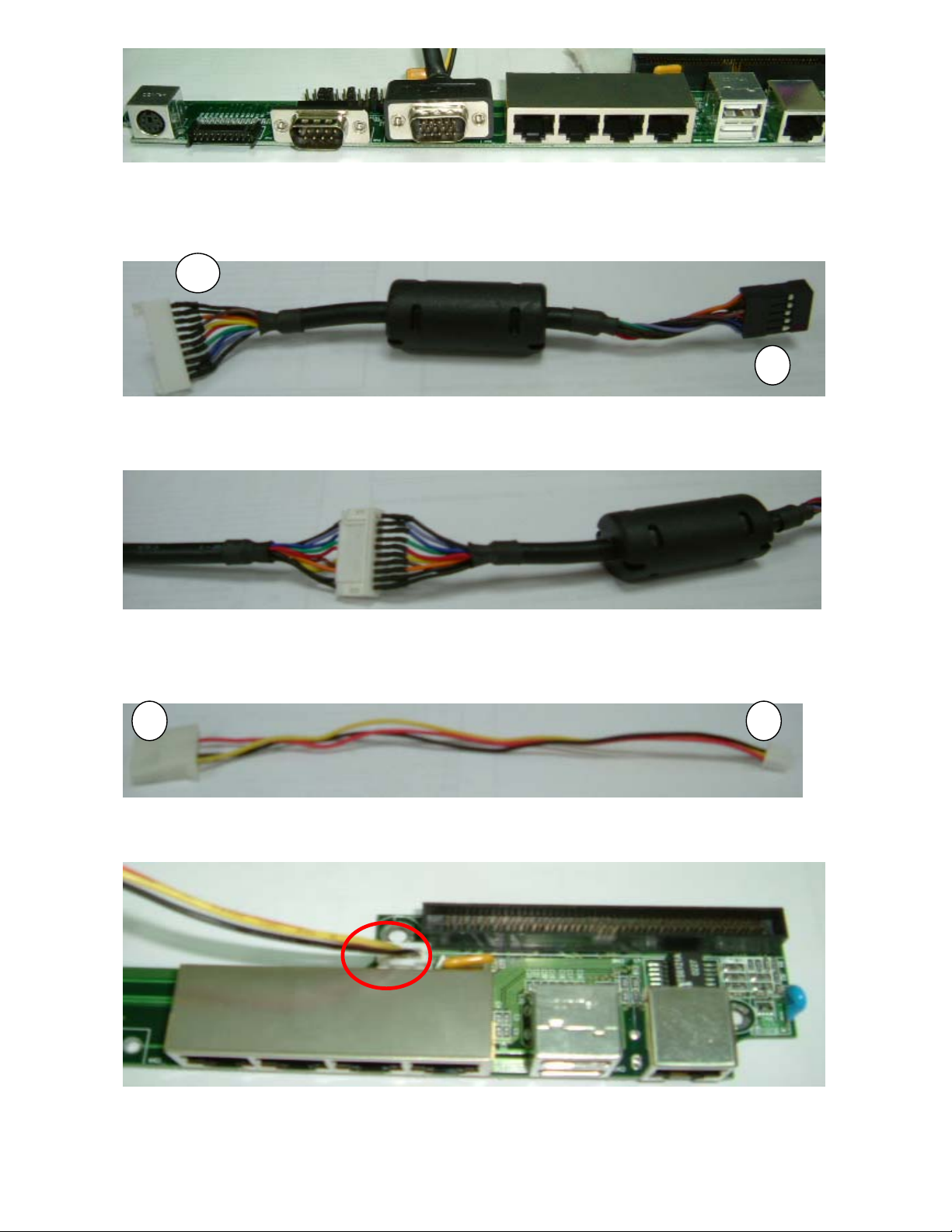
d. Install second display VGA cable replace COM2
C
D
e. Second display VGA cable 2
f. A of second display VGA cable 1 connect to D of second display VGA cable 2
g. Power cable of connector board
h. E of power cable connected to connector board.
EF
16
Page 16
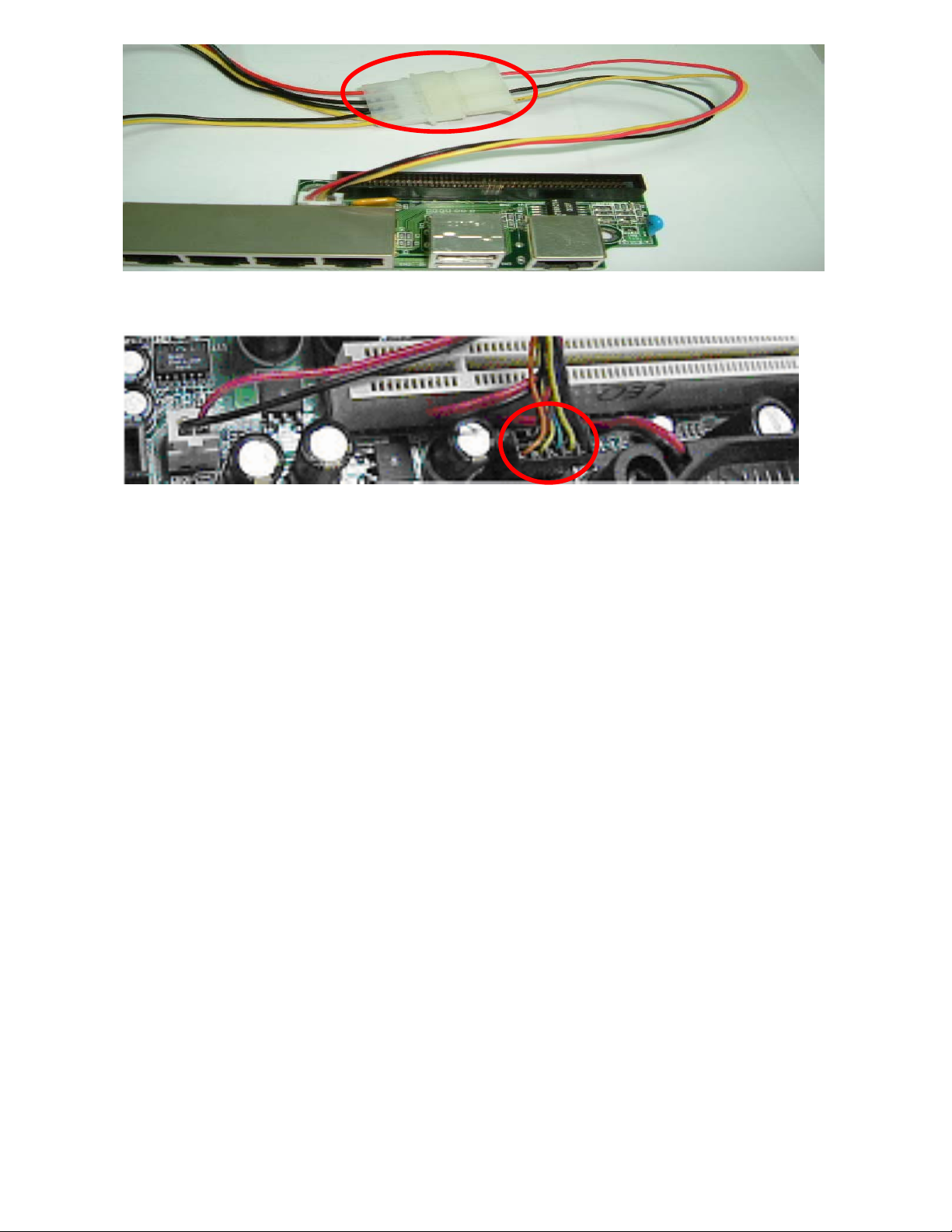
i. B of second display cable 1 connected to F of power cable.
j. C of second display cable 2 connected to main board.
17
Page 17
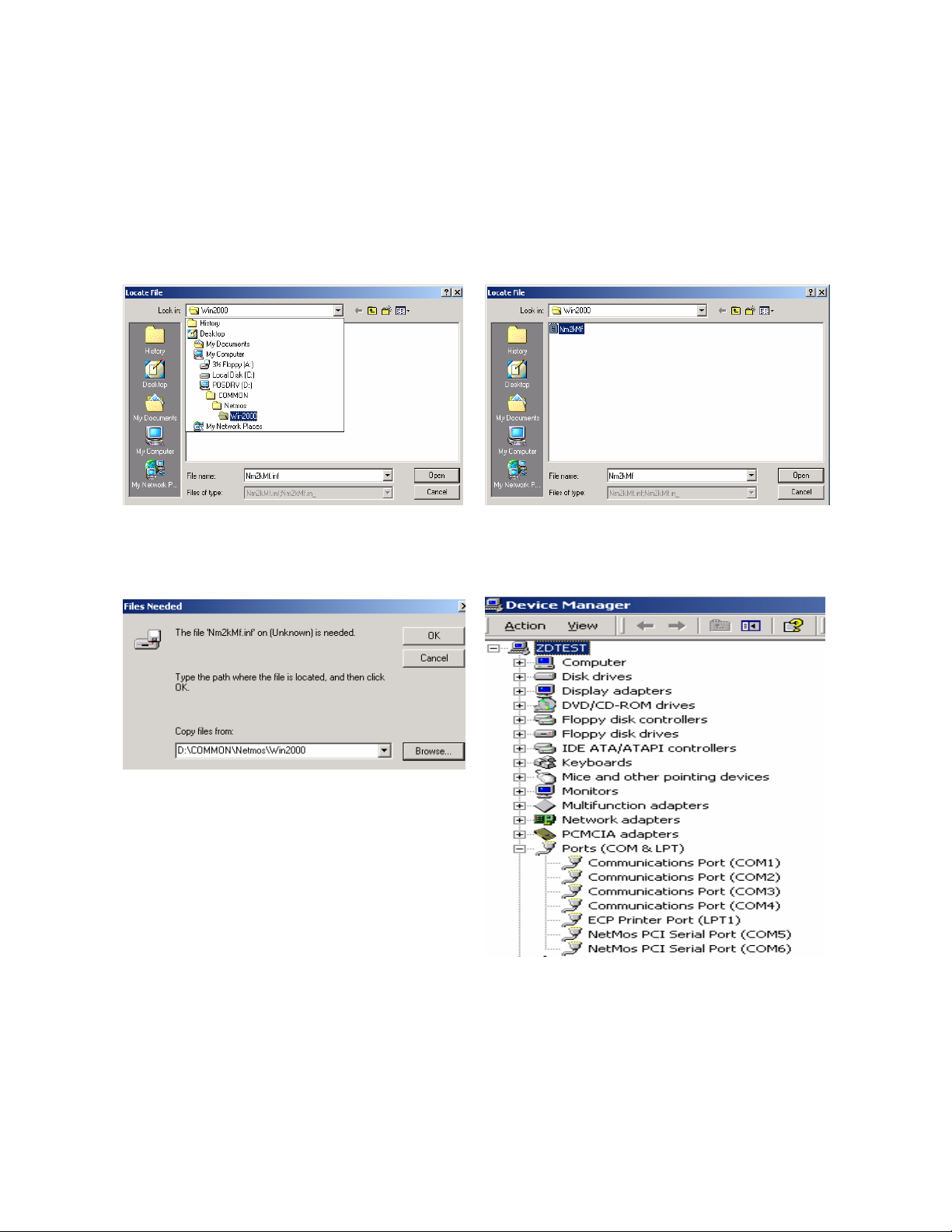
5. Driver Installation
The following procedures are for Windows 2000. Other platforms are si milar.
5.1 Netmos
a. Indicate the location of the Netmos driver b. Choose “Nm2kMf” in the Locate File
window.
c. Click “OK” on the Files Needed window. d. Now the Netmos driver is installed.
18
Page 18
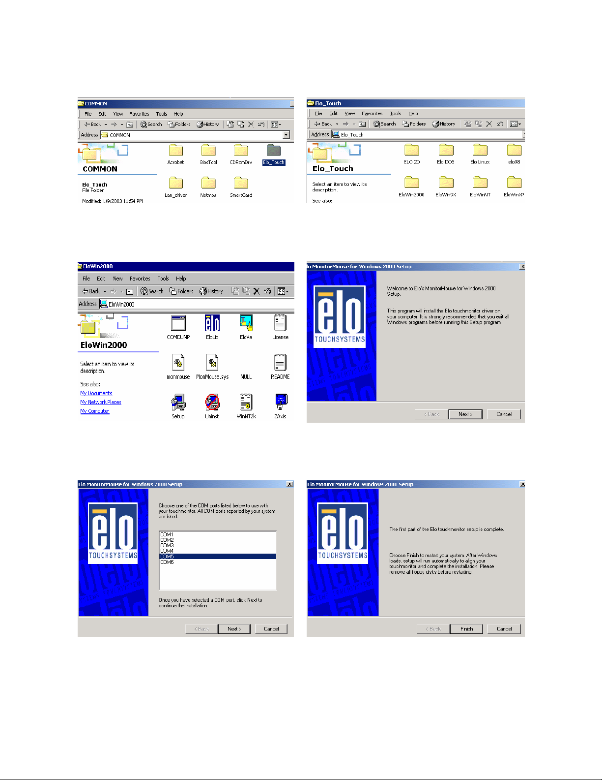
5.2 Elo_Touch
a. Click "COMMON" on the POS driver window.
b. Click "Elo_Touch" on the COMMON
window.
d. Click “Setup” on the EloWin2000 window. e. Click “Next” on the Elo MonitorMouse for
c. Choose the OS to be installed with Elo
_Touch driver.
Windows 2000 Setup window.
d. Choose “COM5” and click “Next” on the
Elo MonitorMouse for Windows 2000
Setup window.
e. Click “Finish” on the Elo MonitorMouse for
Windows 2000 Setup window.
19
Page 19
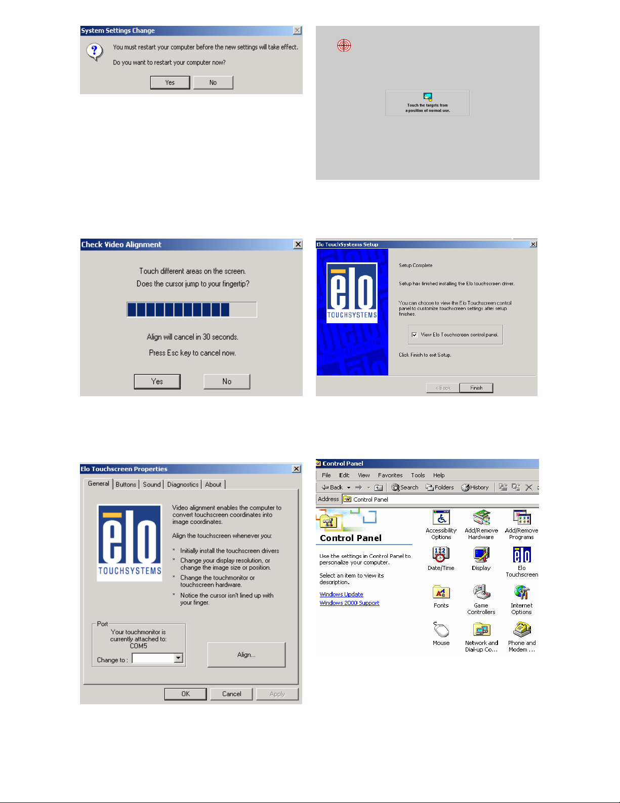
f. Click “Yes” on the System Settings
Change.
g. After the computer restarte d, touch the
targets with your finger for alignm ent.
h. Click “Yes” on the Check Video Alignment
window.
i. Click “Finish” on the “Elo TouchSystem
Setup window.
j. If the cursor is not in sync with your finger
tip, click “Align…” to exe cute the
alignment procedure again, or click “OK”
k. Now the Elo_Touch driver is installed.
20
Page 20
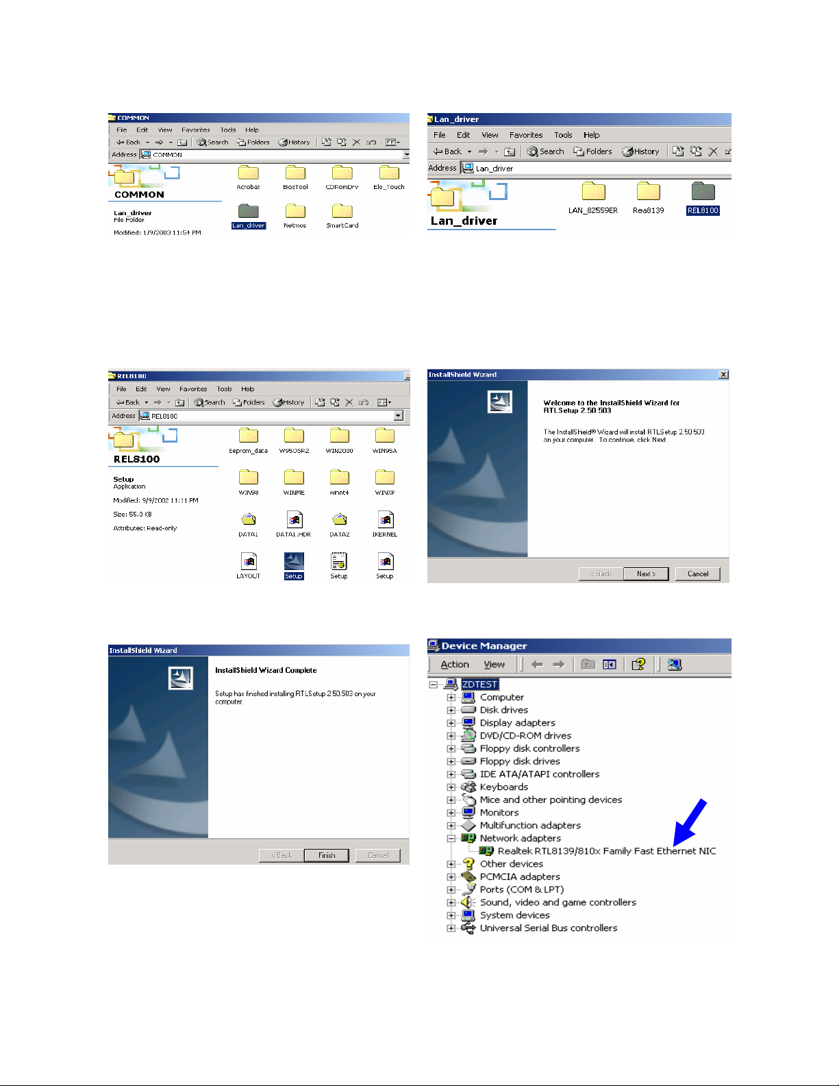
5.3 LAN-driver
a. Click "COMMON" on the POS driver
window.
b. Click “Lan_driver” on the COMMON
window.
d. Click “Setup” on the REL8100 window. e. Click “Next” on the InstallShieild W izard.
c. Click “REL8100” on the Lan_driver
window.
f. Click “Finish” on the InstallShield Wizard. g. Now the Lan_driver is installed.
21
Page 21
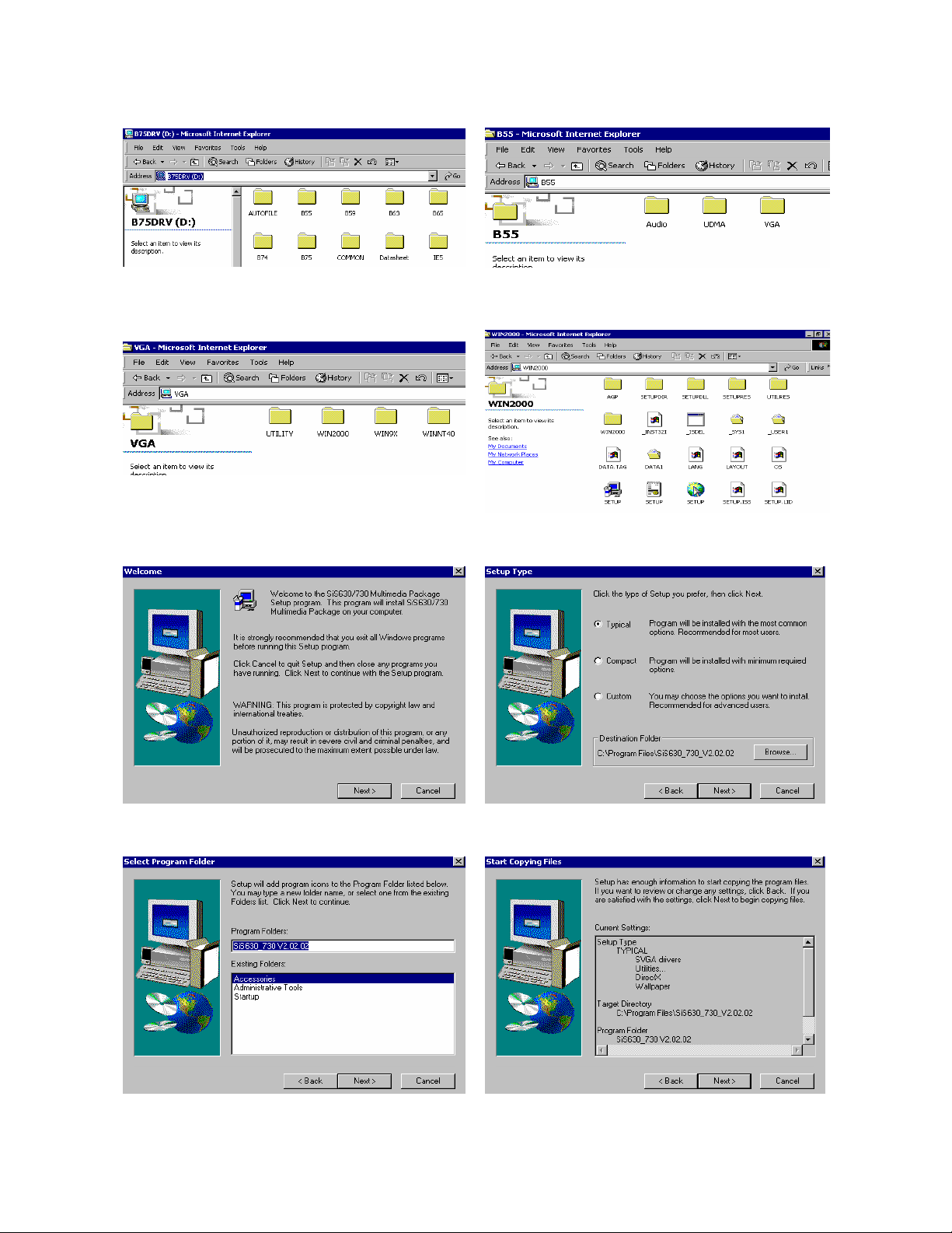
5.4 VGA
a. Click “B55” on the POS driver window. b. Click “VGA” on the B55 window.
c. Click “Win2000” on the VGA window. d. Click “SETUP” On the VGA2000 window.
e. Click “Next” on the Welcome window. f. Click "Next" on the Setup Type window.
g. Click "Next" on the Select Program
Folder window..
h. Click "Next" on the Select Copying Files
window.
22
Page 22
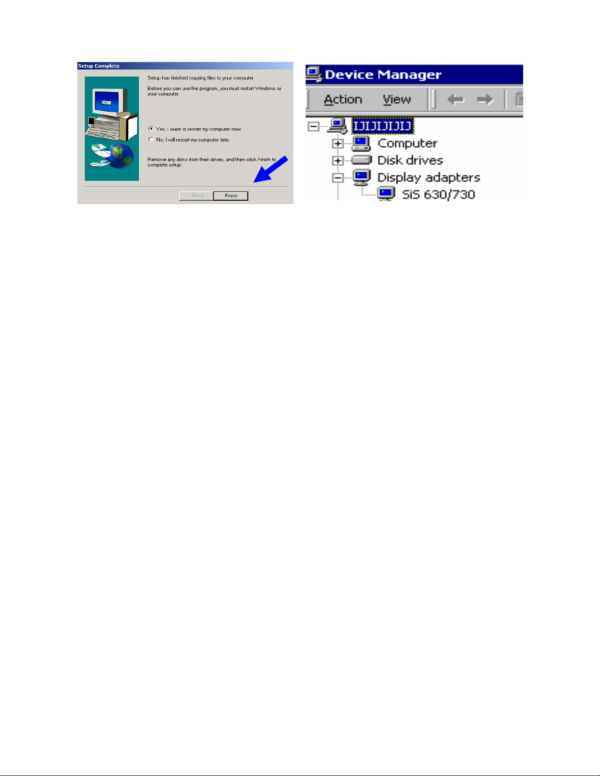
i. Click "Finish" on the Setup Complete
window.
j. Now the VGA driver is installed.
23
Page 23
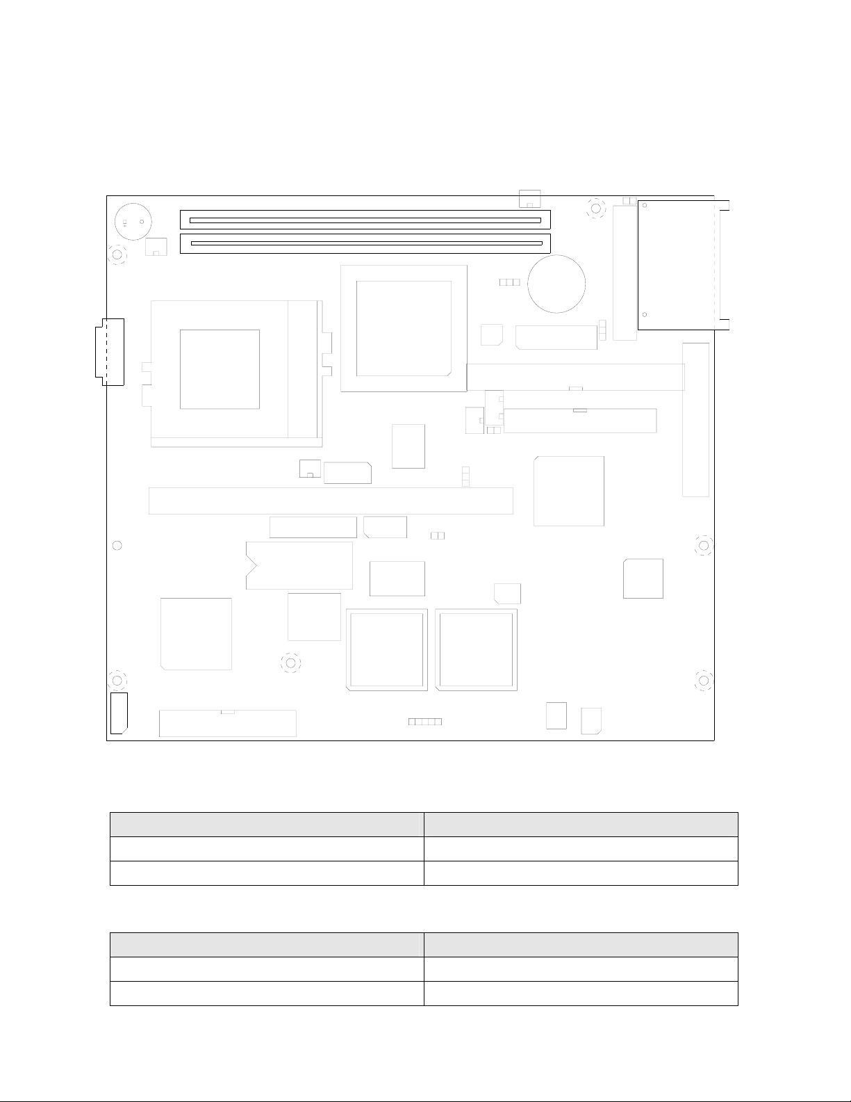
6. Jumper Setting
6.1 B65(POS500) Jumpers and DIP Switches Locations
BZ1
CN4
8
JP5
JP1
CN7
1
CN3
3
4
3
3
1
2
2
1
CN8
1
CN9
2
0
9
4
3
CN1
CN2
0
7
1
U4
CN10
3
A
G
P
JP9
11
12
U3
9
3
F
D
8
S
4
C
2
JP10
9
1
2
I
JP7
1
JP2
1
JP3
3
4
1
2
1
1
JP8
BT1
JP4
1
CN5
CN6
39
40
Intel
PCIset
U21
24
210
23
1
JP12
U15
9
JP13
JP14
26
1
5
1
U19
JP11
U13
2
1
BIOS
U24
U25 U26
0
9
1
CN13
JP15 JP16
2
43
1
44
1
2
1
5
U42
JP17
6
2
5
1
6.1.1 Compact Flash CS Selection * Factory Default
Function JP1
*Master OPEN
Slave SHORT
6.1.2 CMOS Op eration Mode
Function JP2 (SHORT)
*CMOS Normal 2-3
CMOS Reset 1-2
24
Page 24
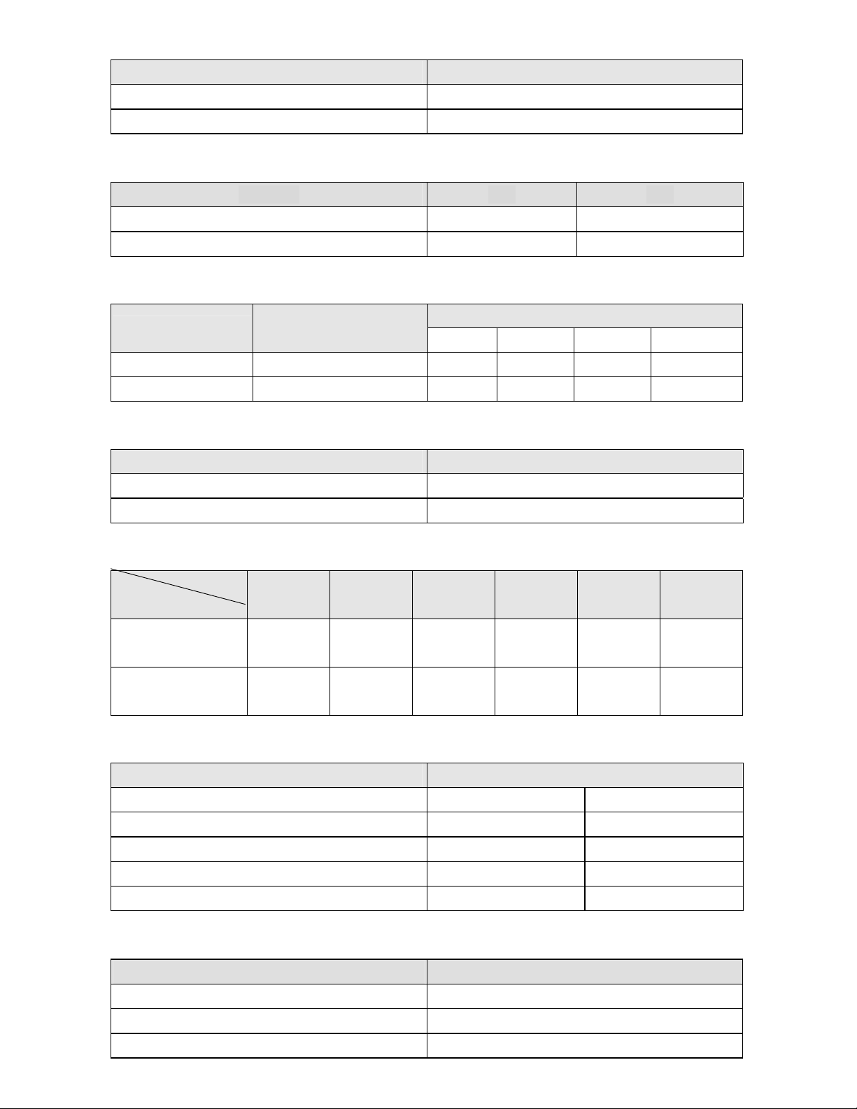
6.1.3 Card Re ader Selection
Function JP3
*Serial 1-2, 3-4 SHORT
Keyboard 1-2, 3-4 OPEN
6.1.4 Power Mode
Function JP5 JP8
ATX Power 2-3 OPEN
*AT Power 1-2 SHORT
6.1.5 System Clock Selection: JP9
CPU Clock
PCI Clock
JP9 (SHORT)
FS0 FS1 FS2 FS3
100.3MHz 33.43 (/3) MHz 1-3 7-9 2-4 10-12
*66.8MHz *33.40 (/2) MHz 1-3 7-9 4-6 10-12
6.1.6 PCI VSB Se l ection: JP10
Function JP10 (SHORT)
*USER 5VSB 2-3
USER 3VSB 1-2
6.1.7 COM5 / COM6 IRQ Selection: JP11
IRQ
5 9 10 11 12 15
COM
COM5
*1-2 3-4 5-6 7-8 9-10 11-12
Touch Screen
COM6
13-14 *15-16 17-18 19-20 21-22 23-24
Pole Display
®
6.1.8 M-Systems Disk On Chip
Address: JP12
Address JP12 (SHORT)
0CC00 - 0CDFF 1-2 9-10
0D000 - 0D1FF 3-4 7-8
*0D400 - 0D5FF 3-4 9-10
0D800 - 0D9FF 5-6 7-8
0DC00 - 0DDFF 5-6 9-10
6.1.9 RAM Backup Address Setting: JP14
RAM DATA Address JP14(SHORT)
*D800 : 0 1-2
D000 : 0 3-4
NC 5-6
25
Page 25
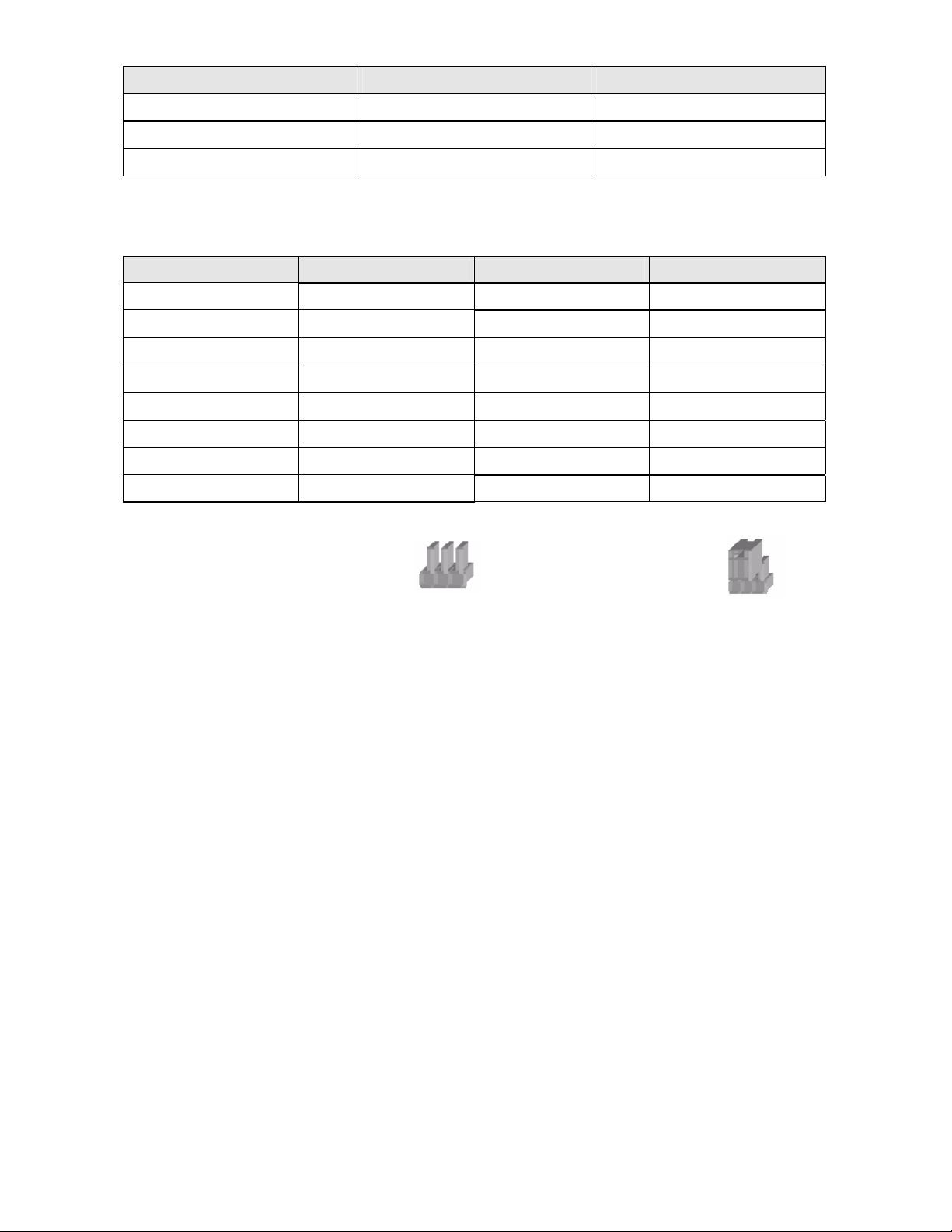
6.1.10 Watch Dog Timer List: JP17
Input / Output Address JP17
Output 205W Watch Dog ON
Input 205R Watch Dog WDI
Input 204R Watch Dog OFF
6.1.11 Watch Dog Timer Programming:
This jumper is designated to do the setting of the W atch Dog Time.
Time 1-2 3-4 5-6
0.1 sec SHORT SHORT SHORT
0.5 sec SHORT SHORT OPEN
1.0 sec SHORT OPEN SHORT
*1.6 sec SHORT OPEN OPEN
10 sec OPEN SHORT SHORT
1 min OPEN SHORT OPEN
10 min OPEN OPEN SHORT
1hr OPEN OPEN OPEN
Note:
OPEN
SHORT
26
Page 26
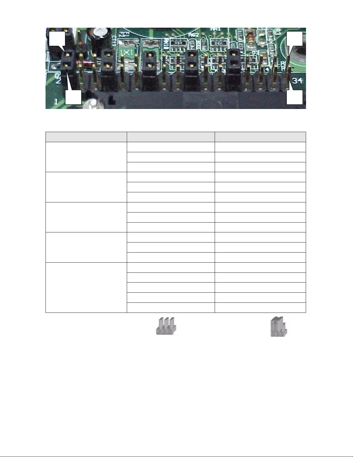
6.1.12 Pin1 function of COM port selection: CN7
2
1
34
33
COM Function Jumper (SHORT)
*DCCD 1-2
1
+5V 3-4
+12V 5-6
*DCCD 7-8
2
+5V 9-10
+12V 11-12
Note:
3
4
6
OPEN
*DCCD 13-14
+5V 15-16
+12V 17-18
*DCCD 19-20
+5V 21-22
+12V 23-24
*DCCD 25-26
+5V 27-28
+12V 29-30
NC 31-32
NC 33-34
SHORT
27
Page 27
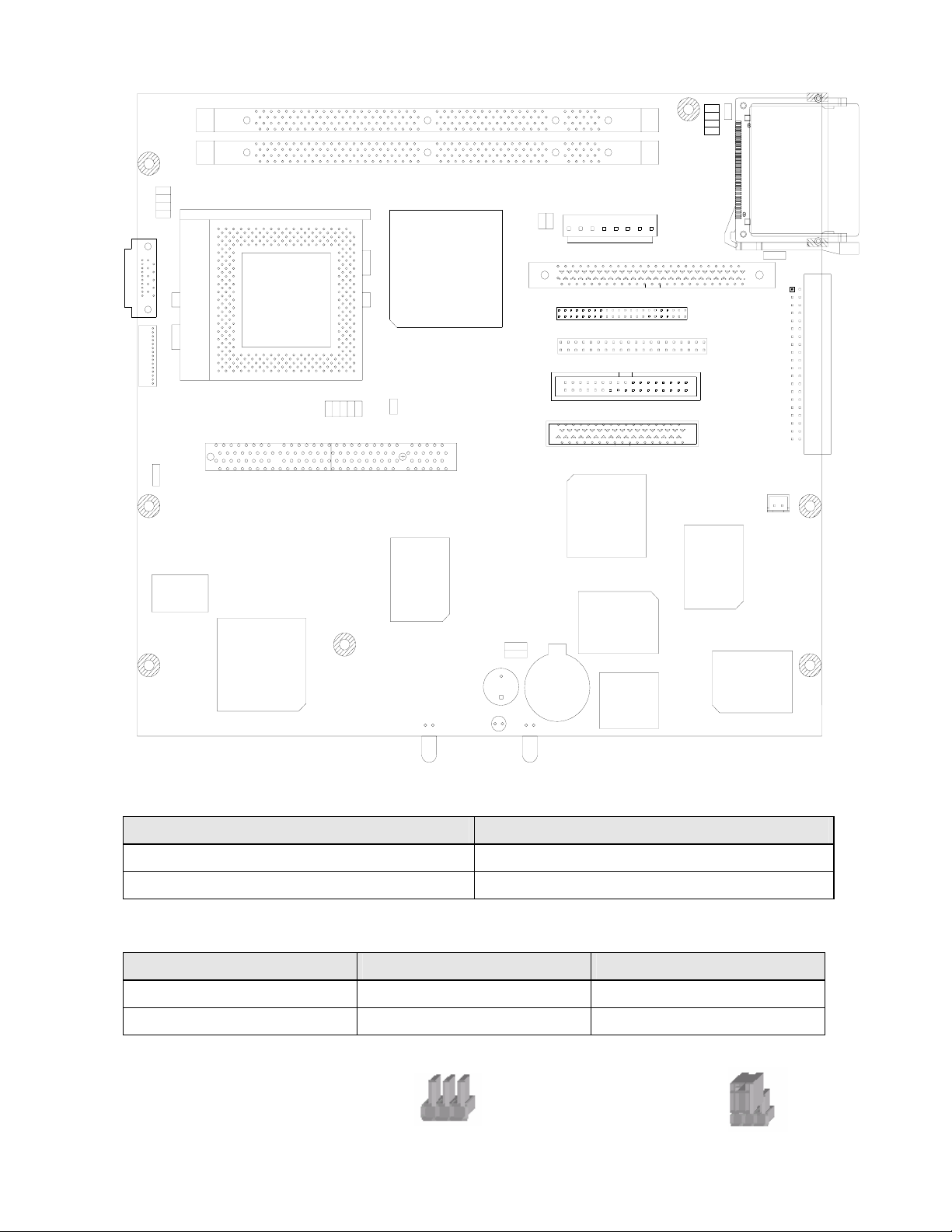
6.2 B55(POS500/505) Jumpers
JP3
12
78
CN4
1
2
CN12
1
JP8
ISL6524
U7
JP9
2
1
PCI1
3
1
U19
U25
U6
SIS630ST
JP10
2
0
1
1
9
U33
5
3
8
9
M
N
1
1
BZ1
JP13
JP15
+
JP1
DIMM2
DIMM1
JP4
2
4
1
3
33
34
1
1
2
1
39
40
CN6
CN7
CN9
CN10
RICOH
JAPAN
8
44
43
1
R5C475II
1AY 750
2
2
1
7
CN5
1
2
1
2
JP2
8
CN1
1
1
3
JP6
CN8
1
2
0
9
4
3
1
JP17
F
H
7
9
6
3
8
W
W83697HF
3
3
RTL8139C
BIOS
BAT1
U30
U27
6.2.1 Power Supply Type * Factory Default Setting
Function JP6
*ATX Power
2-3 (SHORT)
AT Power 1-2 (SHORT)
6.2.2 CMOS Op eration Mode
Function JP13 (SHORT) JP15 (SHORT)
*CMOS Normal 1-2 1-2
CMOS (Cle ar) 2-3 2-3
Note:
OPEN
28
SHORT
Page 28
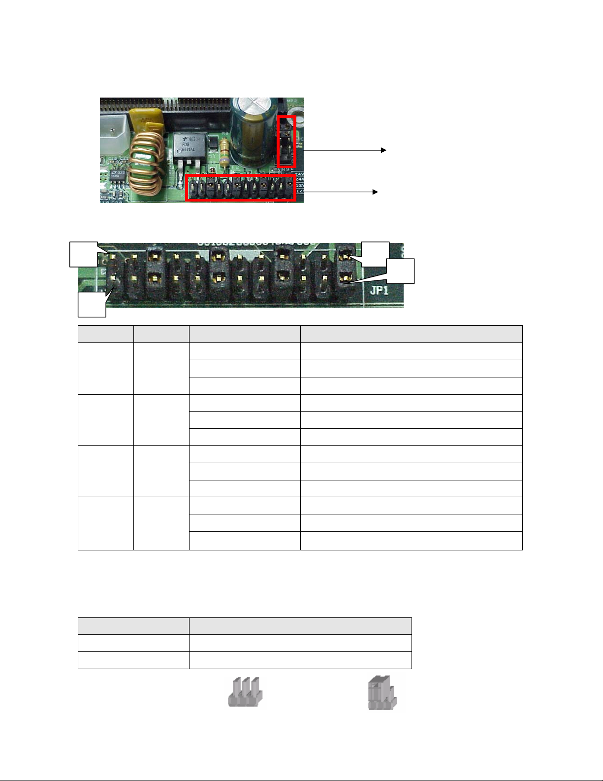
7.B55 I/O Board Jumper Setting
JP2
JP1
7.1 Pin1/Pin9 Function of COM Port Selection: JP1
23
24
COM PIN Function Jumper (SHORT)
*DCCD 1-2
1 1
1 9
6 1
12V 3-4
5V 5-6
*RI 7-8
12V 9-10
5V 11-12
*DCCD 13-14
12V 15-16
1
2
* Factory Default Setting
5V 17-18
*RI 19-20
6 9
12V 21-22
5V 23-24
7.2 Cash Drawer Power Selection: JP2
Function Jumper (SHORT)
*24V 1-2, 3-4
12V 5-6, 7-8
Note:
OPEN
29
SHORT
 Loading...