

FLY SYNTHESIS
02
15/02/11
Placard updated
C. Cosatto
C. Cosatto
C. Cosatto
01
20/12/10
Propeller auto pitch contr.
C. Cosatto
C. Cosatto
C. Cosatto
00
18/11/10
New manual issue
C. Cosatto
C. Cosatto
C. Cosatto
Num.
Date
Description
Issued
Verified
Approved
REVISION
FlySynthesis s.r.l. Reserves in terms of law the exclusive ownership of this manual and also forbids the whole or partial reproduction of it.
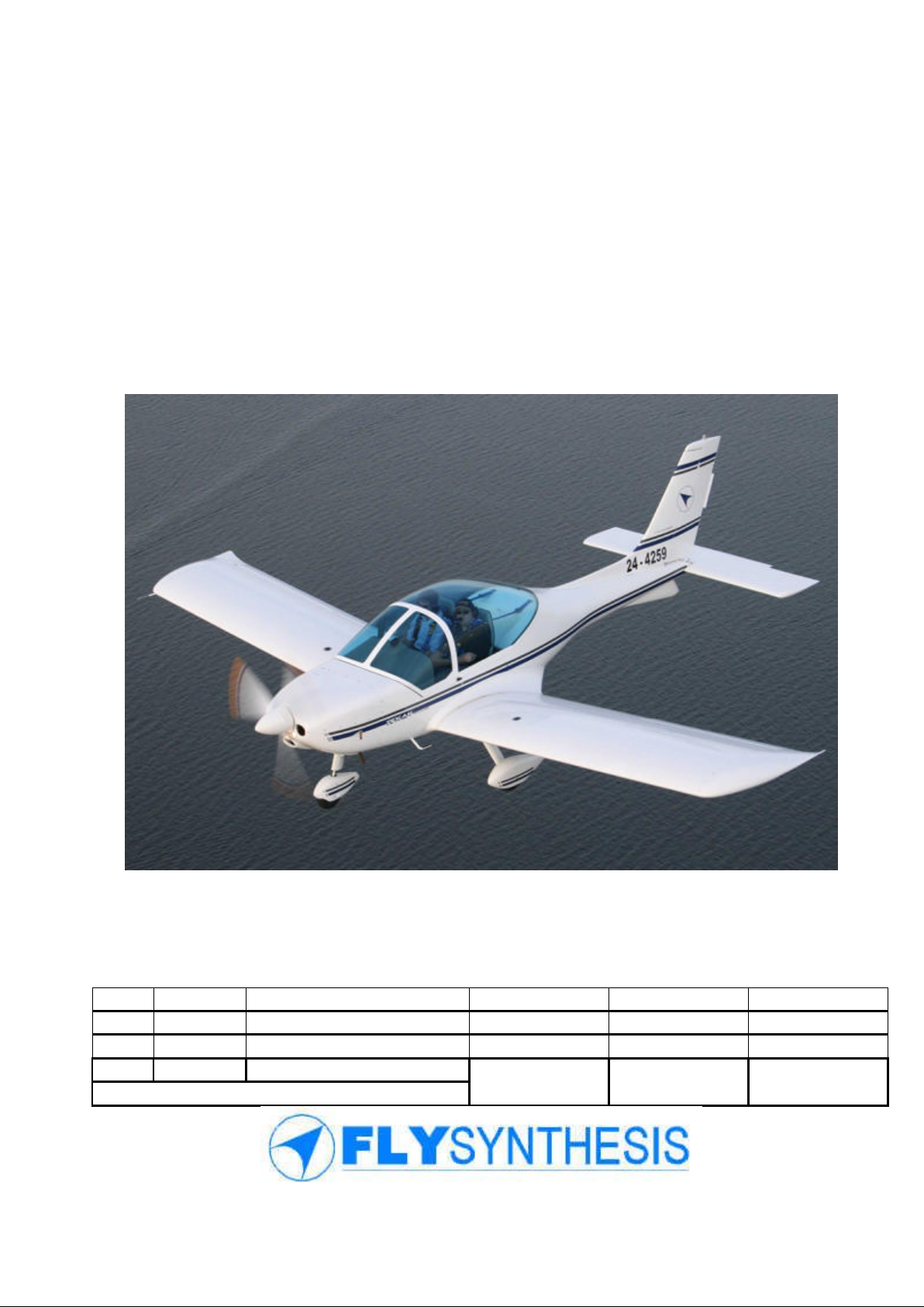
TEXAN TOP CLASS 580 ISR
MAINTENANCE MANUAL
(For Rotax 912 ULS)
2
Provincial Road n.78 Km 12.150
33050 Mortegliano (UD) – Italy
Tel. +39.(0)432.992482 – +39.(0)432.993557
Fax +39.(0)432.931280
Sito web: www.flysynthesis.com
e-mail: info@flysynthesis.com
Maintenance Manual
FLY SYNTHESIS TEXAN
TOP CLASS 580 ISR
(For Rotax 912 ULS
versions)
Identification: MM_TC_580_Rev.2
Page: 2 of 77
Date: 15/02/11
Issued: C. Cosatto
Verified: C. Cosatto
Approved: C. Cosatto
Revision Description:
Placard update
WARNING
Procedures or instructions that if not followed correctly may result in injury or
death
CAUTION
Procedures or instructions that if not followed correctly may result in damage to
the aircraft or its parts
SCOPE
This manual contains the necessary information for safe and efficient Maintenance of the
FLYSYNTHESIS TEXAN TOP CLASS 580 ISR.
NOTE
This manual may be revised in the future and pages/or sections re-issued in part or whole.
Revisions will be available on the Fly Synthesis website www.flysynthesis.com. Any revisions
and/or sections should be printed and replaced in the manual at the earliest possible time for
flight safety. The revisions added to the manual should be logged and recorded in the table
under log of Revisions of this manual, by the owner/user.
DEFINITIONS
Definitions used in this handbook such as WARNING, CAUTION and NOTE are employed
in the following context.
NOTE: Procedures or instructions that is essential to highlight
INTELLECTUAL PROPERTY
The data and information contained in this document is the property of FLYSYNTHESIS
SRL. This document may not be reproduced or transmitted to a third party, in any form or by
any means. Any unauthorised copy or distribution is illegal as per international agreements
relating to property rights.
THIS AIRCRAFT WAS MANUFACTURED IN ACCORDANCE WITH THE FOLLOWING
LIGHT SPORT AIRCRAFT AIRWORTHINESS STANDARDS BCAR Section S, CS-VLA,
F2279, F2295 AND F2483 AND DOES NOT CONFORM TO STANDARD CATEGORY
AIRWORTHNESS REQUIREMENTS.
3
Provincial Road n.78 Km 12.150
33050 Mortegliano (UD) – Italy
Tel. +39.(0)432.992482 – +39.(0)432.993557
Fax +39.(0)432.931280
Sito web: www.flysynthesis.com
e-mail: info@flysynthesis.com
Maintenance Manual
FLY SYNTHESIS TEXAN
TOP CLASS 580 ISR
(For Rotax 912 ULS
versions)
Identification: MM_TC_580_Rev.2
Page: 3 of 77
Date: 15/02/11
Issued: C. Cosatto
Verified: C. Cosatto
Approved: C. Cosatto
Revision Description:
Placard update
Revision No.
Revision
Date
Signature
01
Propeller automatic pitch control system
20/12/10
Cosatto C.
02
Limitations placard updated
15/02/11
Cosatto C.
LOG OF REVISIONS
4
Provincial Road n.78 Km 12.150
33050 Mortegliano (UD) – Italy
Tel. +39.(0)432.992482 – +39.(0)432.993557
Fax +39.(0)432.931280
Sito web: www.flysynthesis.com
e-mail: info@flysynthesis.com
Maintenance Manual
FLY SYNTHESIS TEXAN
TOP CLASS 580 ISR
(For Rotax 912 ULS
versions)
Identification: MM_TC_580_Rev.2
Page: 4 of 77
Date: 15/02/11
Issued: C. Cosatto
Verified: C. Cosatto
Approved: C. Cosatto
Revision Description:
Placard update
Section
Page
Date
Revision
Section
Page
Date
Revision
-
01
18/11/10
0 9 41
18/11/10
0
-
02
18/11/10
0 9 42
18/11/10
0
-
03
18/11/10
0 9 43
18/11/10
0
-
04
18/11/10
0 9 44
18/11/10
0
-
05
18/11/10
0
10
45
18/11/10
0
-
06
18/11/10
0
10
46
18/11/10
0
1
07
18/11/10
0
11
47
18/11/10
0
1
08
18/11/10
0
11
48
18/11/10
0
1
09
18/11/10
0
11
49
18/11/10
0
1
10
18/11/10
0
12
50
18/11/10
0
2
11
18/11/10
0
12
51
21/12/10
1
2
12
18/11/10
0
13
52
18/11/10
0
2
13
18/11/10
0
13
53
18/11/10
0
3
14
18/11/10
0
13
54
18/11/10
0
3
15
18/11/10
0
14
55
18/11/10
0
3
16
18/11/10
0
14
56
18/11/10
0
3
17
18/11/10
0
14
57
18/11/10
0
4
18
18/11/10
0
14
58
18/11/10
0
4
19
18/11/10
0
14
59
18/11/10
0
4
20
18/11/10
0
14
60
18/11/10
0
4
21
18/11/10
0
15
61
18/11/10
0
5
22
18/11/10
0
15
62
18/11/10
0
5
23
18/11/10
0
15
63
18/11/10
0
6
24
18/11/10
0
16
64
18/11/10
0
6
25
18/11/10
0
16
65
18/11/10
0
7
26
18/11/10
0
16
66
18/11/10
0
7
27
18/11/10
0
16
67
18/11/10
0
7
28
18/11/10
0
17
68
18/11/10
0
7
29
18/11/10
0
17
69
15/02/11
2
7
30
18/11/10
0
17
70
21/12/10
1
8
31
18/11/10
0
Appendix
71
18/11/10
0
8
32
18/11/10
0 A 72
18/11/10
0
9
33
18/11/10
0 B 73
18/11/10
0
9
34
18/11/10
0 B 74
18/11/10
0
9
35
18/11/10
0 C 75
21/12/10
1 9 36
18/11/10
0 C 76
21/12/10
1 9 37
18/11/10
0 D 77
18/11/10
0 9 38
18/11/10
0 9 39
18/11/10
0
9
40
18/11/10
0
LOG OF EFFECTIVE PAGES
5
Provincial Road n.78 Km 12.150
33050 Mortegliano (UD) – Italy
Tel. +39.(0)432.992482 – +39.(0)432.993557
Fax +39.(0)432.931280
Sito web: www.flysynthesis.com
e-mail: info@flysynthesis.com
Maintenance Manual
FLY SYNTHESIS TEXAN
TOP CLASS 580 ISR
(For Rotax 912 ULS
versions)
Identification: MM_TC_580_Rev.2
Page: 5 of 77
Date: 15/02/11
Issued: C. Cosatto
Verified: C. Cosatto
Approved: C. Cosatto
Revision Description:
Placard update
SECTION PAGE
1. GENERAL SAFETY INFORMATION 6
1.1 GENERAL SAFETY INFORMATION 7
1.2 OWNERS MAINTENANCE 7
1.3 AIRFRAME 7
1.4 FLIGHT CONTROL SYSTEM 8
1.5 SEATS AND SAFETY BELTS 8
1.6 BAGGAGE COMPARTMENT 8
1.7 PLACARD REPLACEMENT 9
1.8 GROUND HANDLING 9
1.9 TIE DOWN 9
2. EQUIPMENT LIST 10
2.1 TOOLING 11
2.2 OTHER POSSIBLE REQUIRED ITEMS 11
2.3 SOURCES TO PURCHASE PARTS 11
2.4 LIST OF DISPOSABLE PARTS 12
3. ENGINE SPECIFICATIONS 13
3.1 ENGINE SPECIFICATIONS 14
3.2 ROTAX 912 S/ULS 14
3.3 ENGINE OVERHAUL 15
3.4 ENGINE CONTROLS 15
3.5 ENGINE INDICATIONS 15
4. WEIGHT AND BALANCE 17
4.1 INTRODUCTION 18
4.2 WEIGHT LIMITATIONS 18
4.3 CENTRE OF GRAVITY LIMITATIONS 18
4.4 WEIGHING PROCEDURE 18
5. TIRE INFLATION PRESSURE 21
5.1 INTRODUCTION 22
5.2 TIRE INFLATION PRESSURE 22
5.3 CHANGING THE TIRE AND TUBE REPLACEMENT 22
6. APPROVED OILS, FUEL AND QUANTITY 23
6.1 ENGINE OIL 24
6.2 FUEL 24
6.3 FUEL TANK CAPACITY 24
7. FASTENER TORQUE VALUES 25
7.1 RECOMMENDED FASTNER TORQE VALUES 26
7.2 FUSELAGE 26
7.3 ENGINE ASSEMBLY 27
7.4 PROPELLER ASSEMBLY 27
7.5 WING ASSEMBLY 28
7.6 RUDDER/STABILATOR ASSEMBLY 28
7.7 CANOPY ASSEMBLY 29
8. REPORTING POSSIBLE SAFETY OF FLIGHT CONCERNS 30
8.1 REPORTING INSTRUCTIONS 31
8.2 FEEDBACK FORM EXAMPLE 31
9. INSPECTION PROCEEDURES 32
9.1 INSPECTIONS 33
9.2 DAILY INSPECTIONS 33
9.2.1 REFUELING 33
9.2.2 FUEL DRAINING 34
9.3 SCHEDULED INSPECTIONS 34
9.3.1 TIME LIMITED COMPONENTS 34
INDEX

6
Provincial Road n.78 Km 12.150
33050 Mortegliano (UD) – Italy
Tel. +39.(0)432.992482 – +39.(0)432.993557
Fax +39.(0)432.931280
Sito web: www.flysynthesis.com
e-mail: info@flysynthesis.com
Maintenance Manual
FLY SYNTHESIS TEXAN
TOP CLASS 580 ISR
(For Rotax 912 ULS
versions)
Identification: MM_TC_580_Rev.2
Page: 6 of 77
Date: 15/02/11
Issued: C. Cosatto
Verified: C. Cosatto
Approved: C. Cosatto
Revision Description:
Placard update
9.3.2 PROPELLER 34
9.3.3 MAIN LANDING GEAR 34
9.4 PRE-FLIGHT INSPECTIONS 35
9.4.1 NOSE WHEEL 35
9.4.2 PROPELLER 35
9.4.3 ENGINE 35
9.4.4 MAIN LANDING GEAR 35
9.4.5 WINGS 36
9.4.6 FUSELAGE 36
9.4.7 TAIL 36
9.4.8 STABILATOR 36
9.4.9 COCKPIT CHECKS 36
9.5 SCHEDULED INSPECTION CHART 37
10. LANDING GEAR SYSTEM 44
10. LANDING GEAR 45
10.1 BRAKE SYSTEM 45
11. FUEL SYSTEM 46
11.1 FUEL SYSTEM OPERATION 47
11.2 FUEL SYSTEM SCHEMATIC DIAGRAM 48
12. PROPELLER SYSTEM 49
12.1 PROPELLER 50
12.2 APPROVED PROPELLER TYPES 50
13. INSTRUMENTS AND AVIONICS 51
13.1 INSTRUMENTS AND AVIAONICS 52
13.2 BASIC MINIMUM FLIGHT AND ENGINE INSTRUMENTS. 52
13.3 INSTRUMENT PANEL LAYOUT AND LEGEND 53
14. ELECTRICAL SYSTEM 54
14.1 ELECTRICAL SYSTEM 55
14.2 ELECTRICAL POWER SYSTEM SCHEMATIC DIAGRAM 56
14.3 ELECTRICAL BUS SYSTEM SCHEMATIC DIAGRAM 57
14.4 FLAP SYSTEM 58
14.5 FLAP SYSTEM SCHEMATIC DIAGRAM. 59
15. PITOT-STATIC SYSTEM 60
15.1 PITOT-STATIC SYSTEM 61
15.2 PITOT-STATIC WATER TRAPS 61
15.3 PITOT-STATIC INSPECTIONS. 61
15.4 PITOT-STATIC SCHEMATIC DIAGRAM 62
16. STRUCTURAL REPAIRS AND ALTERATIONS 63
16.1 STRUCTURAL REPAIRS AND ALTERATIONS 64
16.2 DAMAGE TO THE COMPOSITE STRUCTURES 64
16.3 LINE MAINTENACE 64
16.4 HEAVY MAINTENANCE 64
16.5 MAJOR REPAIR, ALTERATION OR MAINTENACE 64
16.6 HEAVY LANDING 64
16.7 EXCEEDING ENGINE LIMITS 64
16.8 EXCEEDING AIRPLANE LIMITS 65
16.9 ENGINE MOUNT CHECKS 65
17 PAINTING AND COATINGS 65
17.1 PAINTINGS AND COATING 68
17.2 PLACARDS 68
18. APPENDIX 70
A. DEFINITIONS 71
B. ABBREVIATIONS 72
C. SUPPLEMENTRY APPROVED OPTIONAL EQUIPMENT 74
D. FEEDBACK FORM 76

7
Provincial Road n.78 Km 12.150
33050 Mortegliano (UD) – Italy
Tel. +39.(0)432.992482 – +39.(0)432.993557
Fax +39.(0)432.931280
Sito web: www.flysynthesis.com
e-mail: info@flysynthesis.com
Maintenance Manual
FLY SYNTHESIS TEXAN
TOP CLASS 580 ISR
(For Rotax 912 ULS
versions)
Identification: MM_TC_580_Rev.2
Page: 7 of 77
Date: 15/02/11
Issued: C. Cosatto
Verified: C. Cosatto
Approved: C. Cosatto
Revision Description:
Placard update
SECTION 1
GENERAL SAFETY INFORMATION
Title Page
1.1 General Safety Information 8
1.2 Owner maintenance 8
1.3 Airframe 8
1.4 Flight control system 9
1.5 Seats and safety belts 9
1.6 Baggage compartment 9
1.7 Placard replacement 10
1.8 Ground handling 10
1.9 Tie down 10
8
Provincial Road n.78 Km 12.150
33050 Mortegliano (UD) – Italy
Tel. +39.(0)432.992482 – +39.(0)432.993557
Fax +39.(0)432.931280
Sito web: www.flysynthesis.com
e-mail: info@flysynthesis.com
Maintenance Manual
FLY SYNTHESIS TEXAN
TOP CLASS 580 ISR
(For Rotax 912 ULS
versions)
Identification: MM_TC_580_Rev.2
Page: 8 of 77
Date: 15/02/11
Issued: C. Cosatto
Verified: C. Cosatto
Approved: C. Cosatto
Revision Description:
Placard update
1.1 GENERAL SAFETY INFORMATION
This manual contains recommended procedures and instructions for ground handling,
servicing and maintaining the TEXAN TOP CLASS 580 ISR. The procedures described
are to be used in addition to the particular governing body‘s regulations for each country
where the aircraft is being flown. Where a maintenance procedure contravenes local
regulations, the procedures of the local governing body will take precedence. This manual
may refer you to the engine manual(s) for maintenance required for the relevant engine.
Maintenance instructions are divided to scheduled and unscheduled tasks. Scheduled
tasks are carried at fixed intervals, either flight hours or periods of time, e.g. at each
100hrs, or once a year which ever comes first.
Unscheduled tasks are those required when the airplane condition if affected after
damage is discovered or some unusual event like a heavy landing.
1.2 OWNER MAINTENACE
The Texan Top Class 580 ISR has been designed as a simple aircraft that can be
maintained by owners. Fly Synthesis allows normal maintenance up to 100 hourly
servicing to be carried out by the owner. This includes:
Oil and Oil filter changes
Fuel filter changes
Brake pad changes
Spark plug changes
Tire changes
Fly Synthesis recommends that any aircraft being used for flight training or for hire/reward
operation be maintained by an approved maintenance person or organisation.
1.3 AIRFRAME
The fuselage, wings and tail are constructed from composite materials. Carbon fibre is
used in highly loaded parts of all the structure, like wing spars. The fuselage is made
using a composite skin, bulkheads and stringer construction. Sandwich honeycomb is
used where required, from the firewall to the tail. The engine is installed on a steel engine
mount connected to the firewall. The engine cowling is achieved with two composite
material parts, an upper and lower cowling, fixed together with the cam-lock system. The
engine compartment is made from steel firewall. The wings are made of a composite skin
and ribs with one main spar, connecting both wings together in the centre of the fuselage.
Wing-fuselage loads are transmitted through four bolts from the root ribs of each wing to
two cross antitorsional tubes in the fuselage construction. An aerodynamic fairing, called
Karman, covers the fuselage / wing root area. The cockpit canopy is made of two parts.
The forward fixed windshield is installed on the cockpit roll bar, designed to protect the
occupants in case of turn over. The aft part of the canopy is designed to move backwards
to open the cockpit. When closed, the canopy is held in place by two locks on each side,
four locks all together.
WARNING: The four locks must be engaged and locked during flight.
9
Provincial Road n.78 Km 12.150
33050 Mortegliano (UD) – Italy
Tel. +39.(0)432.992482 – +39.(0)432.993557
Fax +39.(0)432.931280
Sito web: www.flysynthesis.com
e-mail: info@flysynthesis.com
Maintenance Manual
FLY SYNTHESIS TEXAN
TOP CLASS 580 ISR
(For Rotax 912 ULS
versions)
Identification: MM_TC_580_Rev.2
Page: 9 of 77
Date: 15/02/11
Issued: C. Cosatto
Verified: C. Cosatto
Approved: C. Cosatto
Revision Description:
Placard update
1.4 FLIGHT CONTROL SYSTEM
The airplane has standard three axis controls, with dual stick and dual rudder pedals.
All control surfaces are made from composite material. The control surfaces are mounted
on metal hinges and in-turn operated by metal mechanisms. All three control surfaces
mass weight balanced to prevent flutter. The pitch is controlled by the stabilator,
commonly known as flying tail. There is no fixed elevator section and a negatively geared
trim tab is used to position the stabilator in the correct pitch and also to trim the aircraft.
The two control sticks in the cockpit are inter-connected and push-pull aluminium rods
transfer the movement to the stabilator. The mechanical trim is achieved by changing the
zero position of the geared tab. The manual trim lever is positioned between the seats
and it moves the trim through a push-pull flexible cable, an optional electric trim is also
available. Roll control is by ailerons. Push-pull rods operate the ailerons. These are
differential ailerons where the angular movement up is greater then the angular
movement down. Directional control is by a rudder installed on the vertical fin stabilizer.
Rudder pedal motion is transmitted via flexible steel cables to the rudder bell-crank. The
rudder pedals are connected at the front of the aircraft to the steerable nose wheel, which
completes the rudder control loop. A spring system help to centralize the rudder and
improve pilot‘s control feel.
CAUTION
Do not operate rudder pedals whilst stationary. Excessive pressure applied to
rudder pedals may result in damage to the rudder control pedal structure.
1.5 SEATS AND SAFETY BELTS
Pilot and passenger seats are made from composite materials and installed on the cockpit
floor. The seat bottom can be removed to enable inspection of the controls below the
seat. Each seat vertical back is adjustable on the ground before flight in 1 of 5 positions,
to suit pilot and passenger‘s size. Seat covers are fastened via Velcro strips and easily
removed for cleaning and inspection.
Each seat is equipped with safety belts, which are locked together with a bayonet quick
release latching system. The safety belts are attached to the main structure and each can
be adjusted for occupant comfort. Belts should be replaced if frayed, cut, stitching is
broken or latching defective.
1.6 BAGGAGE COMPARTMENT
WARNING: Never try to change seat adjustment in flight!
The baggage compartment is located behind the seats. Maximum baggage weight when
distributed evenly is 16 kg. Loose Items stored in the baggage area must be secured to
prevent unwanted movement during flight in turbulent conditions. An optional bigger
baggage compartment is available on request.
10
Provincial Road n.78 Km 12.150
33050 Mortegliano (UD) – Italy
Tel. +39.(0)432.992482 – +39.(0)432.993557
Fax +39.(0)432.931280
Sito web: www.flysynthesis.com
e-mail: info@flysynthesis.com
Maintenance Manual
FLY SYNTHESIS TEXAN
TOP CLASS 580 ISR
(For Rotax 912 ULS
versions)
Identification: MM_TC_580_Rev.2
Page: 10 of 77
Date: 15/02/11
Issued: C. Cosatto
Verified: C. Cosatto
Approved: C. Cosatto
Revision Description:
Placard update
1.7 PLACARD REPLACEMENT
If placards need to be replaced you can order them through Flysynthesis Srl at
www.flysynthesis.com or contact your local representative.
1.8 GROUND HANDLING
The TEXAN aircraft is very light and should always be moved by hand.
Moving the aircraft is accomplished by using the prop hub to pull the aircraft forward, it is
best to position the propeller in the horizontal position and hold the propeller close to the
hub. For rearward motion holding onto the rear vertical fin allows for easy rearward
motion.
WARNING
Do not spin the propeller whilst the engine is hot as it may fire when the propeller is
moved and result in injury.
Always ensure that master and Ignition are OFF.
Always treat the propeller as LIVE! IT KILLS!
Never approach the propeller when someone is in the aircraft.
Never use any of the control surfaces to move the aircraft for ground handling.
1.9 TIE DOWN
When mooring the aircraft in the open, head into wind if possible. Secure control surfaces
by tying the control stick back firmly with a latched seat belt.
Tie ropes to the designated wing attachment points located underneath the wing nearest
the wing tip. Anchor the rope approximately 30 degrees to the vertical, outboard of the
wing attachment point. Ensure sufficient slack as not to place strain on the wing in the
event of tire deflation whilst in the tied down position. A third rope is anchored around the
Stabiltator hinge and secured rearward in the same manner as the wings.

11
Provincial Road n.78 Km 12.150
33050 Mortegliano (UD) – Italy
Tel. +39.(0)432.992482 – +39.(0)432.993557
Fax +39.(0)432.931280
Sito web: www.flysynthesis.com
e-mail: info@flysynthesis.com
Maintenance Manual
FLY SYNTHESIS TEXAN
TOP CLASS 580 ISR
(For Rotax 912 ULS
versions)
Identification: MM_TC_580_Rev.2
Page: 11 of 77
Date: 15/02/11
Issued: C. Cosatto
Verified: C. Cosatto
Approved: C. Cosatto
Revision Description:
Placard update
SECTION 2
EQUIPMENT AND PARTS LIST
Title Page
2.1 Tooling 12
2.2 Other possible required items 12
2.3 Sources to purchase parts 12
2.4 List of disposable replacement parts 13
12
Provincial Road n.78 Km 12.150
33050 Mortegliano (UD) – Italy
Tel. +39.(0)432.992482 – +39.(0)432.993557
Fax +39.(0)432.931280
Sito web: www.flysynthesis.com
e-mail: info@flysynthesis.com
Maintenance Manual
FLY SYNTHESIS TEXAN
TOP CLASS 580 ISR
(For Rotax 912 ULS
versions)
Identification: MM_TC_580_Rev.2
Page: 12 of 77
Date: 15/02/11
Issued: C. Cosatto
Verified: C. Cosatto
Approved: C. Cosatto
Revision Description:
Placard update
Component
Source
Composite airframe parts
Flysynthesis Srl or local distributor.
Non Composites hardware eg
Bolts screws etc.
Flysynthesis Srl or local distributor.
Other aircraft specialty hardware shops.
Avionics and Instruments
Flysynthesis Srl or local distributor.
Other aircraft avionic and instrument
specialty shops.
Propeller Parts
Flysynthesis Srl or local distributor.
Propeller manufacturer eg. DUC France, GT
Tonini (Italy) or Pipistrel (Slovenia).
2.1 TOOLING
Tooling required to do maintenance on this aircraft is listed below. Please note that the list
may not be comprehensive
Loctite (243, 567 and Antisieze Lubricant # 76764) for the frame section.
Open ended Metric Spanner set
Torque wrench
Air Pump
Various petroleum lubricants
Dry Lubricant – lubricant that doesn‘t attract dust after application.
UV Resistant Tie wraps, and tooling
Metric Hex key set
Gasoline resistant thread sealant tape
Various general care items
Metric Socket Wrench Set
Pliers and Wise Grips
Phillips and Regular Screw Driver Set
Flexible neck funnel
2.2 OTHER POSSIBLE REQUIRED ITEMS
Safety wire and Safety Pins
WD-40, CRC or another water displacement compound
Telescopic mirror
Good flash light
5x and 10x magnifying glass and or video inspection equipment
2.3 SOURCES TO PURCHASE PARTS
Parts can be purchased from the following sources
13
Provincial Road n.78 Km 12.150
33050 Mortegliano (UD) – Italy
Tel. +39.(0)432.992482 – +39.(0)432.993557
Fax +39.(0)432.931280
Sito web: www.flysynthesis.com
e-mail: info@flysynthesis.com
Maintenance Manual
FLY SYNTHESIS TEXAN
TOP CLASS 580 ISR
(For Rotax 912 ULS
versions)
Identification: MM_TC_580_Rev.2
Page: 13 of 77
Date: 15/02/11
Issued: C. Cosatto
Verified: C. Cosatto
Approved: C. Cosatto
Revision Description:
Placard update
Part
Comment
Fuel Filters
Disposable fuel filters or metal mesh non-disposable
ones specified by the respective engine
manufacture‘s manual must be used.
Air Filters
Disposable air and fuel filters are available from local
distributor. If soiled they will be replaced with new
ones and old ones discarded. Old filters should be
disposed of as per local laws
Tires
Standard front tires: 4x4-ply (100/75-5)
Standard rear tires: 13x5x6-ply
Large rear tires: 15x6x6-ply
Tires and tubes available from local distributor.
Worn tires should be disposed of as per local laws.
Oil Filters
Oil filters should be properly disposed of along with
the oil at each oil change, according to local laws.
Landing light
Automotive and auto-electrical shop.
Fuel Line
When fuel line has to be replaced, the old one should
be properly disposed of, according to local laws.
Water hoses
When hoses have to be replaced, the old one should
be properly disposed of, according to local laws.
Replacement hose should be of the same type and
grade as the original.
Battery
When the sealed maintenance free battery is to be
replaced, the older battery should be properly
recycled according to local laws.
Spark plugs
Spark plugs are available from Engine manufacturer
Or local distributor.
Brake pads
Brake pads are specially made and available from the
aircraft manufacturer or local representative.
2.4 LIST OF DISPOSABLE REPLACEMENT PARTS
Dispose of all disposable parts properly following local laws and regulations

14
Provincial Road n.78 Km 12.150
33050 Mortegliano (UD) – Italy
Tel. +39.(0)432.992482 – +39.(0)432.993557
Fax +39.(0)432.931280
Sito web: www.flysynthesis.com
e-mail: info@flysynthesis.com
Maintenance Manual
FLY SYNTHESIS TEXAN
TOP CLASS 580 ISR
(For Rotax 912 ULS
versions)
Identification: MM_TC_580_Rev.2
Page: 14 of 77
Date: 15/02/11
Issued: C. Cosatto
Verified: C. Cosatto
Approved: C. Cosatto
Revision Description:
Placard update
SECTION 3
ENGINE
Title Page
3.1 Engine specification 15
3.2 Rotax 912 S/ULS 15
3.3 Engine overhaul 16
3.4 Engine controls 16
3.5 Engine indications 16
15
Provincial Road n.78 Km 12.150
33050 Mortegliano (UD) – Italy
Tel. +39.(0)432.992482 – +39.(0)432.993557
Fax +39.(0)432.931280
Sito web: www.flysynthesis.com
e-mail: info@flysynthesis.com
Maintenance Manual
FLY SYNTHESIS TEXAN
TOP CLASS 580 ISR
(For Rotax 912 ULS
versions)
Identification: MM_TC_580_Rev.2
Page: 15 of 77
Date: 15/02/11
Issued: C. Cosatto
Verified: C. Cosatto
Approved: C. Cosatto
Revision Description:
Placard update
Version
Performance
Torque
Max.RPM
kw hp rpm
Nm ft.lb rpm
912 S/ULS
69.0 95.0 5500
128 94 5100
Continuous
max.5 min
73.5* 100* 5800*
*with Rotax air box and
exhaust system
5800
Bore
Stroke
Displacement
Compression ratio
84mm ( 3.31in )
61.0mm ( 2.4 in )
1352cm ( 82.6 cu.in.)
10.5 : 1
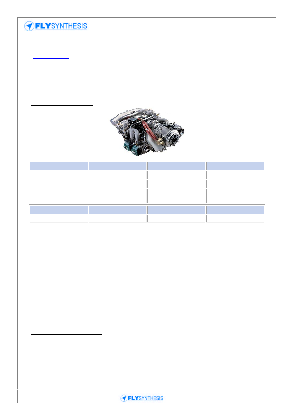
3.1 ENGINE SPECIFICATION
The approved power plant installations for the TEXAN TOP CLASS 580 ISR is the
ROTAX 912 ULS. For full detail of engine construction see ROTAX manuals.
3.2 ROTAX 912 S/ULS
3.3 ENGINE OVERHAUL
Rotax: After 1500 hours for Rotax 912ULS
3.4 ENGINE CONTROLS
Engine control is by one throttle control, operating both carburettors simultaneously. A
choke is provided for starting a cold engine. The twin-magneto ignition system is
controlled by the Master Key.
The engine starter is actuated by the Master Key, that control the starter relay, when the
master switch is ON. With master switch OFF the starter will not operate.
An Electric fuel pump supplies fuel pressure prior to the engine starting and running and is
used as back up for the engine driven fuel pump in case of failure.
3.5 ENGINE INDICATIONS
The rpm indicator indicates engine speed (RPM). This is an electronic unit.
The cylinder head temperature (CHT) indicator shows engine temperature.
The oil pressure indicator indicates oil pressure.
A separate indicator indicates the oil temperature. An Exhaust Gas Temperature system
(EGT) is also installed.

16
Provincial Road n.78 Km 12.150
33050 Mortegliano (UD) – Italy
Tel. +39.(0)432.992482 – +39.(0)432.993557
Fax +39.(0)432.931280
Sito web: www.flysynthesis.com
e-mail: info@flysynthesis.com
Maintenance Manual
FLY SYNTHESIS TEXAN
TOP CLASS 580 ISR
(For Rotax 912 ULS
versions)
Identification: MM_TC_580_Rev.2
Page: 16 of 77
Date: 15/02/11
Issued: C. Cosatto
Verified: C. Cosatto
Approved: C. Cosatto
Revision Description:
Placard update
The fuel pressure indicator indicates fuel pressure with the engine pump and/or aux
electric fuel pump in use. This fuel pressure indicator is a mechanical unit.
A standard sealed accumulating hours-meter (Hobbs meter), counts the total time the
ignition key is switched on. An optional air switch may be fitted that accumulates time on
an air switch clock when the aircraft attains a speed greater than 30 knots. The air switch
time can be used for purposes of airframe and engine maintenance.

17
Provincial Road n.78 Km 12.150
33050 Mortegliano (UD) – Italy
Tel. +39.(0)432.992482 – +39.(0)432.993557
Fax +39.(0)432.931280
Sito web: www.flysynthesis.com
e-mail: info@flysynthesis.com
Maintenance Manual
FLY SYNTHESIS TEXAN
TOP CLASS 580 ISR
(For Rotax 912 ULS
versions)
Identification: MM_TC_580_Rev.2
Page: 17 of 77
Date: 15/02/11
Issued: C. Cosatto
Verified: C. Cosatto
Approved: C. Cosatto
Revision Description:
Placard update
Intentionally left blank

18
Provincial Road n.78 Km 12.150
33050 Mortegliano (UD) – Italy
Tel. +39.(0)432.992482 – +39.(0)432.993557
Fax +39.(0)432.931280
Sito web: www.flysynthesis.com
e-mail: info@flysynthesis.com
Maintenance Manual
FLY SYNTHESIS TEXAN
TOP CLASS 580 ISR
(For Rotax 912 ULS
versions)
Identification: MM_TC_580_Rev.2
Page: 18 of 77
Date: 15/02/11
Issued: C. Cosatto
Verified: C. Cosatto
Approved: C. Cosatto
Revision Description:
Placard update
SECTION 4
WEIGHTS AND BALANCE
Title Page
4.1 Introduction 19
4.2 Weight Limitations 19
4.3 Center of Gravity Limitations 19
4.4 Weighing Procedure 19
19
Provincial Road n.78 Km 12.150
33050 Mortegliano (UD) – Italy
Tel. +39.(0)432.992482 – +39.(0)432.993557
Fax +39.(0)432.931280
Sito web: www.flysynthesis.com
e-mail: info@flysynthesis.com
Maintenance Manual
FLY SYNTHESIS TEXAN
TOP CLASS 580 ISR
(For Rotax 912 ULS
versions)
Identification: MM_TC_580_Rev.2
Page: 19 of 77
Date: 15/02/11
Issued: C. Cosatto
Verified: C. Cosatto
Approved: C. Cosatto
Revision Description:
Placard update
Exceeding the Centre of Gravity limits is
PROHIBITED
Exceeding the maximum weights is
PROHIBITED
4.1 INTRODUCTION
In order to obtain the best flight performance, safety, stability and control, the airplane
must be loaded within the Centre of Gravity (balance) inside the prescribed limits.
Operation beyond the prescribed limits may cause instability and loss of control, or too
much stability with not enough control. Both cases will lead to unsafe conditions and could
result in an accident, with serious or fatal personal injury.
Weight limitations are important as the performance and the integrity of the structure will
decrease to below acceptable values when exceeding the maximum Take-Off Weight.
Operation at weights above the limits may thus lead to unsafe conditions and could result
in a serious accident.
4.2 WEIGHT LIMITATIONS
Rotax 912
Maximum Take-Off Weight 580 kg
Maximum Pilot and Passenger Weight 180 kg
Minimum Solo Pilot Weight 70 kg
Luggage Compartment, 16 kg
Minimum Empty Weight 330 kg
4.3 CENTER OF GRAVITY LIMITATIONS
Forward Limit: 377 mm behind the reference datum (27% MAC)
Aft Limit: 504 mm behind the reference datum (36% MAC)
The longitudinal location of the Centre of Gravity (CG) is measured as the distance behind
a reference datum (RD).
The reference datum is defined as the vertical plane of the leading edge of the wing, when
the airplane is level.
The mean Aerodynamic Chord (MAC) is the average chord of a wing, for this airplane it is
1400 mm.
The 0% of the MAC is the reference datum (RD).
The location of the CG can be defined by reference to the % MAC.
4.4 WEIGHING PROCEDURE
Weighing must be done in a closed hangar with no chance of wind affecting the
measurements.
The floor must be level, preferably smooth concrete or any other smooth hard surface.
20
Provincial Road n.78 Km 12.150
33050 Mortegliano (UD) – Italy
Tel. +39.(0)432.992482 – +39.(0)432.993557
Fax +39.(0)432.931280
Sito web: www.flysynthesis.com
e-mail: info@flysynthesis.com
Maintenance Manual
FLY SYNTHESIS TEXAN
TOP CLASS 580 ISR
(For Rotax 912 ULS
versions)
Identification: MM_TC_580_Rev.2
Page: 20 of 77
Date: 15/02/11
Issued: C. Cosatto
Verified: C. Cosatto
Approved: C. Cosatto
Revision Description:
Placard update
The airplane is complete, painted and all instruments and accessories installed.
The airplane is serviced with full engine oil, full engine coolant fluid, full brake fluid, fuel
tank drained and filled with the specified amount of the unusable fuel (TEXAN-2 litres-with
dual tanks).
In order to achieve an acceptable accuracy, the scales used for weighing should have the
following capacities:
Nose wheel - Up to 100 kgs
Main wheel – each - Up to 120 kgs
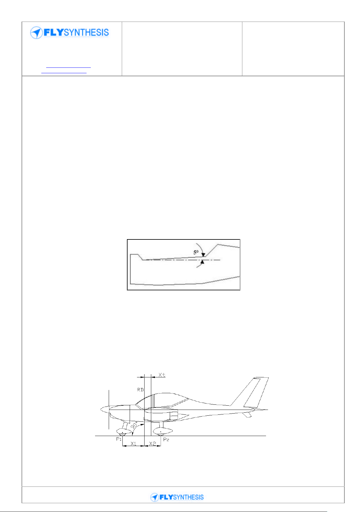
1. Put the airplane on the three scales,
2. Block the wheels to prevent the airplane from rolling off the scales,
3. Check that the airplane is level. The check is done by measuring on the cockpit
sidewall top, which should be 5º nose down when the airplane is level. Place
pieces of wood with different thickness under the wheels, as required to have the
airplane level. Close the canopy before reading the scales.
4. Lower two plumb lines from the leading edge of the inboard wing section, left and
right wings. Mark the points on the floor and draw a straight line on the floor
(parallel to the wing span). This is the reference datum (RD),
5. Measure the longitudinal distance from the RD to the axle of the nose wheel. This
is the value X1. Record the value in the weight report. This value should be with a
minus sign,
6. Measure the longitudinal distance from the RD to the axle of the main wheels. This
is the value X2. Record the value in the weight report,
7. Note the weight of each scale and record in the weight report,
21
Provincial Road n.78 Km 12.150
33050 Mortegliano (UD) – Italy
Tel. +39.(0)432.992482 – +39.(0)432.993557
Fax +39.(0)432.931280
Sito web: www.flysynthesis.com
e-mail: info@flysynthesis.com
Maintenance Manual
FLY SYNTHESIS TEXAN
TOP CLASS 580 ISR
(For Rotax 912 ULS
versions)
Identification: MM_TC_580_Rev.2
Page: 21 of 77
Date: 15/02/11
Issued: C. Cosatto
Verified: C. Cosatto
Approved: C. Cosatto
Revision Description:
Placard update
8. Remove the airplane from the scales, record the weight of the supporting wood
pieces of each scale as tare weight for that scale,
9. Change the left and right scales for the main wheels, and repeat the weighing
procedure again. Record results in the weight report,
10. Calculate the average weight value for each wheel.
11. Calculate the Empty Weight and the Empty Centre of Gravity position for the
airplane.
X1 is the distance from nose wheel axle centerline to projection of RD.
X2 is the distance from main wheel axle centerline to projection of RD.
The standard distance is:
X1 = 925mm (±0.5%)
X2 = 655mm (±0.5%).
The formula for CG calculation is as follows:
Xt = ML / PT . [CofG position in mm on the wing chord]
Where:
ML = (P2DX + P2SX) x X2 - P1 x X1
Xt% = (Xt / MAC) x 100 [CG position in percentage to the wing chord]
ML = Empty weight moment
P2DX , P2SX = Weight measured on main wheel
P1 = Weight measured on nose wheel
NOTE: DX = RHS SX = LHS
The first recording of the Weighing Report & the Center of Gravity Position of the aircraft
is taken at the factory before the delivery of the same aircraft. The Factory Weight and
Balance report will accompany the Aircraft on delivery.
Every variation due to the installation of new components or repairs and painting,
implicate a new calculation of the empty weight and the relative positioning of the center
of gravity.
Any weight and Balance changes should be recorded into the aircraft log book.

22
Provincial Road n.78 Km 12.150
33050 Mortegliano (UD) – Italy
Tel. +39.(0)432.992482 – +39.(0)432.993557
Fax +39.(0)432.931280
Sito web: www.flysynthesis.com
e-mail: info@flysynthesis.com
Maintenance Manual
FLY SYNTHESIS TEXAN
TOP CLASS 580 ISR
(For Rotax 912 ULS
versions)
Identification: MM_TC_580_Rev.2
Page: 22 of 77
Date: 15/02/11
Issued: C. Cosatto
Verified: C. Cosatto
Approved: C. Cosatto
Revision Description:
Placard update
Title Page
5.1 Introduction 23
5.2 Tire Inflation pressure 23
5.3 Tire and tube replacement procedure 23
SECTION 5
TIRE INFLATION PRESSURE
23
Provincial Road n.78 Km 12.150
33050 Mortegliano (UD) – Italy
Tel. +39.(0)432.992482 – +39.(0)432.993557
Fax +39.(0)432.931280
Sito web: www.flysynthesis.com
e-mail: info@flysynthesis.com
Maintenance Manual
FLY SYNTHESIS TEXAN
TOP CLASS 580 ISR
(For Rotax 912 ULS
versions)
Identification: MM_TC_580_Rev.2
Page: 23 of 77
Date: 15/02/11
Issued: C. Cosatto
Verified: C. Cosatto
Approved: C. Cosatto
Revision Description:
Placard update
5.1 INTRODUCTION
It is essential to maintain your tires in good condition. When checking tire pressure,
examine for tire wear, cuts, bruises and slippage. Remove oil, grease and mud from tires
with soap and water.
NOTE: Recommended tire pressures should be maintained, especially in cold weather.
Any drop in temperature of air inside the tire causes a corresponding drop in tire pressure.
5.2 TIRE PRESSURES
Main wheel tire 4.00x6‖ or (13x5x6), inflation pressure 2.2 – 2.4 bar (32 – 35 psi)
Large main wheel tire 15x6x6, inflation pressure 2.2 – 2.4 bar (32 – 35 psi)
Nose wheel tire 4.00x4‖,(100/75-5) inflation pressure: 1.8 bar (26.1 psi)
5.3 CHANGING THE TIRE AND TUBE REPLACEMENT.
The wheel rims used in this aircraft are of the split rim type and as such generally require
an inner tube. Should the tube or tire require replacement the following procedure will be
of assistance.
Raise the aircraft to suspend the wheel off the ground
Remove the wheel fairing
Remove axle from wheel housing
Unbolt the disk brake from rim ( rear wheel only)
Remove wheel from axle assembly
Split rim by undoing the rim bolts
NOTE: ensure no pressure is left in tire prior to splitting the rim.
Replace defective tire or tube
Re bolt the rim being careful not to pinch the inner tube
Inflate the tire to correct tire pressure
Check bearing for smoothness in rotation
Submerse the inflated tire in water and check for leaks
Re-assemble the wheel to the axle in reverse order.

24
Provincial Road n.78 Km 12.150
33050 Mortegliano (UD) – Italy
Tel. +39.(0)432.992482 – +39.(0)432.993557
Fax +39.(0)432.931280
Sito web: www.flysynthesis.com
e-mail: info@flysynthesis.com
Maintenance Manual
FLY SYNTHESIS TEXAN
TOP CLASS 580 ISR
(For Rotax 912 ULS
versions)
Identification: MM_TC_580_Rev.2
Page: 24 of 77
Date: 15/02/11
Issued: C. Cosatto
Verified: C. Cosatto
Approved: C. Cosatto
Revision Description:
Placard update
SECTION 6
APPROVED OILS, FUELS AND QUANTITY
Title Page
6.1 Engine Oil 25
6.2 Fuel 25
6.3 Fuel tank capacity 25

25
Provincial Road n.78 Km 12.150
33050 Mortegliano (UD) – Italy
Tel. +39.(0)432.992482 – +39.(0)432.993557
Fax +39.(0)432.931280
Sito web: www.flysynthesis.com
e-mail: info@flysynthesis.com
Maintenance Manual
FLY SYNTHESIS TEXAN
TOP CLASS 580 ISR
(For Rotax 912 ULS
versions)
Identification: MM_TC_580_Rev.2
Page: 25 of 77
Date: 15/02/11
Issued: C. Cosatto
Verified: C. Cosatto
Approved: C. Cosatto
Revision Description:
Placard update
6.1 ENGINE OIL
For detailed information on recommended oil grades refer to the ROTAX operator‘s
manual.
Recommended engine oils for Rotax engines running on Unleaded Auto Fuel
Oil Capacity: 3.0 Litres
MOBIL 1 (5w- 30) or (15W-50)
SHELL Advance VSX 4 (10W-40) or (15W-50)
SHELL Advance Ultra 4 (10W-40)
VALVOLINE Dura blend Synthetic (10W-40)
PENNZOIL Motorcycle Motor Oil (20W-50)
Recommended engine oils for Rotax engines running on AVGAS fuel
SHELL Advance VSX 4 (10W-40) or (15W-50)
SHELL Formula (10W-30) or (20W-50)
SHELL Formula Synthetic Blend (10W-30)
VALVOLINE Dura blend Synthetic (10W-40)
6.2 FUEL
For detailed information on the approved fuels, refer to the ROTAX operator‘s manual.
Do not use fuel additives such as Octane boosters or MOGAS with any level of added
Alcohol.
6.3 FUEL TANK CAPACITY:
- Fuel tank capacity 2 x 50 L
- Unusable fuel 2 L
- Usable fuel 98 L
NOTE: for fuel system schematic drawing see section 11 in this manual.

26
Provincial Road n.78 Km 12.150
33050 Mortegliano (UD) – Italy
Tel. +39.(0)432.992482 – +39.(0)432.993557
Fax +39.(0)432.931280
Sito web: www.flysynthesis.com
e-mail: info@flysynthesis.com
Maintenance Manual
FLY SYNTHESIS TEXAN
TOP CLASS 580 ISR
(For Rotax 912 ULS
versions)
Identification: MM_TC_580_Rev.2
Page: 26 of 77
Date: 15/02/11
Issued: C. Cosatto
Verified: C. Cosatto
Approved: C. Cosatto
Revision Description:
Placard update
Title Page
7.1 Recommended Fastener torque values 27
7.2 Fuselage 27
7.3 Engine assembly 28
7.4 Propeller assembly 28
7.5 Wing assembly 29
7.6 Rudder and Stabilator assembly 29
7.7 Canopy assembly 30
SECTION 7
FASTENER TORQUE VALUES

27
Provincial Road n.78 Km 12.150
33050 Mortegliano (UD) – Italy
Tel. +39.(0)432.992482 – +39.(0)432.993557
Fax +39.(0)432.931280
Sito web: www.flysynthesis.com
e-mail: info@flysynthesis.com
Maintenance Manual
FLY SYNTHESIS TEXAN
TOP CLASS 580 ISR
(For Rotax 912 ULS
versions)
Identification: MM_TC_580_Rev.2
Page: 27 of 77
Date: 15/02/11
Issued: C. Cosatto
Verified: C. Cosatto
Approved: C. Cosatto
Revision Description:
Placard update
7.2 FUSELAGE
Quantity
TORQUE
MAIN LANDING GEAR STRUCTURE ON FUSELAGE
N°24
screws M6
Kg*mt 0,75
MAIN LANDING GEAR LEG ATTACH ON GEAR STRUT
N°2 screws
M8
Kg*mt 1,6
WHEEL AXLE ATTACH ON MAIN LANDING GEAR LEG
N°2 screws
M6
Kg*mt 0,75
PLATE ATTACHMENT TO FIREWALL
N°7 screws
M8
Kg*mt 1,6
PLATE ATTACHMENT TO SHOCK ABSORBER SYSTEM
N°2 screws
M8
Kg*mt 2,4
FLAP CONTROL SHAFT ATTACHMENT TO FUSELAGE
N°1 screw
M6
Kg*mt 0,75
AILERON CONTROL STICK UNDER SEATS FLOOR IN
FUSELAGE
N°16
screws M5
Kg*mt 0,42
FLAP ACTUATOR HINGES
N°2 screws
¼‖
Kg*mt 0,9
FLAP CONTROL STICKS (INSIDE FUSELAGE)
N°8 screws
M6
Kg*mt 0,75
CLOCHE SYSTEM
N°8 screws
M6
Kg*mt 0,75
BOWDEN CABLE ATTACHMENT
N°6 screws
M5
Kg*mt 0,42
ENGINE MOUNT ATTACHMENT AT FIREWALL
N°4 screws
M8
Kg*mt 2,4
PINCER DISCK BRAKE ATTACHMENT INTO WHEEL AXLE
N°4 screws
M6
Kg*mt 0,75
PINCER TO PINCER SUPPORT GROUP
N°8 screws
M6
Kg*mt 0,75
FAIRING TO WHEEL AXEL
N°6 screws
M6
Kg*mt 0,75
PULLEY TO PULLEY SUPPORT
N°1 screw
M8
Kg*mt 1,6
SUPPORT ROD TO PULLEY
N°1 screw
M6
Kg*mt 0,42
7.1 RECOMMENDED FASTENER TORQUE VALUES
*The following table presents the required torque values of the different assemblies in the
airplane. It is assumed that the bolts and nylon locknuts are in new condition and are
made from standard finish 8.8 coarse metric hardware. Final tightening sequence is
achieved smoothly and slowly until full torque has been obtained.

28
Provincial Road n.78 Km 12.150
33050 Mortegliano (UD) – Italy
Tel. +39.(0)432.992482 – +39.(0)432.993557
Fax +39.(0)432.931280
Sito web: www.flysynthesis.com
e-mail: info@flysynthesis.com
Maintenance Manual
FLY SYNTHESIS TEXAN
TOP CLASS 580 ISR
(For Rotax 912 ULS
versions)
Identification: MM_TC_580_Rev.2
Page: 28 of 77
Date: 15/02/11
Issued: C. Cosatto
Verified: C. Cosatto
Approved: C. Cosatto
Revision Description:
Placard update
7.3 ENGINE ASSEMBLY
Quantity
TORQUE
ALTERNATING CURRENT RECTIFIER ON FIRE BULKHEAD
N°2 screws
M5
Kg*mt 0,42
START RELAY ON FIRE BULKHEAD
N°2 screws
M5
Kg*mt 0,42
CAPS BULKHEAD ON FIRE BULKHEAD
N°8 screws
M5
Kg*mt 0,42
DECANTER FILTER ON RIGHT COVER
N°2 screws
M5
Kg*mt 0,42
TAKE OFF PUMP ON FIRE BULKHEAD
N°1 screw
M6
Kg*mt 0,75
OIL RADIATOR SUPPORT ON FIRE BULKHEAD
N°2 screws
M5
Kg*mt 0,42
AIR FILTER SUPPORT ON FIRE BULKHEAD
N°2 screws
M5
Kg*mt 0,42
ENGINE TO ENGINE MOUNTING PYLON
N°4 screws
M10
Kg*mt 3,5
WATER MANIFOLD ASSEMBLY
N°2 screws
M6
Kg*mt 1
CAP PUMP
N°5 screws
M6
Kg*mt 1
HEAD AIR INTAKE
N°8 screws
M6
Kg*mt 1
INDUCTION MANIFOLD
N°8 screws
M6
Kg*mt 1
FUEL PUMP
N°2 dadi M8
Kg*mt 2,4
AIRBOX SUPPORT
N°2 screws
M6
Kg*mt 1
OVERFLOW BOTTLE SUPPORT TO ENGINE MOUNTING
PYLON
N°1 screw
M6
Kg*mt 0,75
OIL MANIFOLD SUPPORT TO ENGINE MOUNTING PYLON
N°2 screws
M6
Kg*mt 1
WATER RADIATOR
N°4 screws
M6
Kg*mt 0,75
FASCETTE TUBI ACQUA
N°8
Kg*mt 3,5
EXHAUST MANIFOLD
N°8 dadi M8
Kg*mt 2,4
FUEL DEVICE SUPPORT TO ENGINE
N°2 screws
M6
Kg*mt 0,75
FUEL DEVICE TO SUPPORT
N°2 screws
M4
Kg*mt 0,2
7.4 PROPELLER ASSEMBLY
Quantity
TORQUE
PROPELLER TO ENGINE (STANDARD WOOD PROPELLER)
N°6 screws
M8
Kg*mt 1,6
PROPELLER TO ENGINE (CARBONFIBRE PROPELLER)
N°6 screws
M8
Kg*mt 2,4
SPINNER TO PLATE (STANDARD)
N°6 screws
M5
Kg*mt 0,42

29
Provincial Road n.78 Km 12.150
33050 Mortegliano (UD) – Italy
Tel. +39.(0)432.992482 – +39.(0)432.993557
Fax +39.(0)432.931280
Sito web: www.flysynthesis.com
e-mail: info@flysynthesis.com
Maintenance Manual
FLY SYNTHESIS TEXAN
TOP CLASS 580 ISR
(For Rotax 912 ULS
versions)
Identification: MM_TC_580_Rev.2
Page: 29 of 77
Date: 15/02/11
Issued: C. Cosatto
Verified: C. Cosatto
Approved: C. Cosatto
Revision Description:
Placard update
SPINNER TO PLATE (IDROVARIO TWOBLADES PROPELLER)
N°6 screws
M5
Kg*mt 0,42
SPINNER TO PLATE (IDROVARIO THREEBLADES
PROPELLER)
N°9 screws
M5
Kg*mt 0,42
SPINNER TO PLATE (PIPISTREL THREEBLADES PROPELLER)
N°9 screws
M5
Kg*mt 0,42
SPINNER TO PLATE (QUINTI AVIO THREEBLADES
PROPELLER)
N°9 screws
M5
Kg*mt 0,42
7.5 WINGS ASSEMBLY
Quantity
TORQUE
COMB HINGES ON SPARE
N°16
screws
M10
Kg*mt 4,6
ANGLE SUPPORT OF MECHANISM PIN ON WING PYLONS
N°8 screws
M5
Kg*mt 0,42
PIN AIRELONS MECHANISM
N° 2 screws
M6
Kg*mt 0,75
PYLON TO WING(FLAP AND AIRELONS)
N° 32
screws M5
Kg*mt 0,42
FLAP/AIRELONS ALLIGNMENT REGULATION BLADES ON
WING PYLONS
N°16
screws M6
Kg*mt 0,75
FLAP/AIRELONS MECHANISM BUSH ON WING PYLONS
N° 8 screws
M6
Kg*mt 0,75
UNIBALL OF AIRELONS CONTROL BAR INSIDE THE WINGS
N° 6 screws
Kg*mt 0,75
FUELTANK CONTROL LEVEL
N°10
screws M5
Kg*mt 0,42
FUELTANK FRAME ON ROOT WING RIB
N°24
screws M5
Kg*mt 0,42
OPENING FUELTANK ON WING
N°12
screws M5
Kg*mt 0,42
TIP ON WING
N°38
screws M4
Kg*mt 0,2
FLAP CONTROL BAR ON FLAP SURFACE
N°4 screws
M6 N.C.S.
Kg*mt 0,75
SEMIWING JOINT PIN TO FUSELAGE
N°4 screws
M8 N.C.S
Kg*mt 2,4
JOINT PIN
N°2 perni
M12
Kg*mt 9,0
AILERON BALANCING WEIGHT TO AILERON PYLON
N°8 screws
M5
Kg*mt 0,42
7.6 RUDDER / STABILATOR ASSEMBLY
Quantity
TORQUE
RUDDER HINGE - FUSELAGE
N° 2 screws
M6
Kg*mt 0,75
RUDDER HINGE – RUDDER
N° 8 screws
M5
Kg*mt 0,42
TRIM BALANCING WEIGHT
N° 2 screws
M5
Kg*mt 0,42
HORIZONTAL STABILIZER HINGE-HORIZONTAL STABILIZER
N° 3 screws
M6
Kg*mt 0,75

30
Provincial Road n.78 Km 12.150
33050 Mortegliano (UD) – Italy
Tel. +39.(0)432.992482 – +39.(0)432.993557
Fax +39.(0)432.931280
Sito web: www.flysynthesis.com
e-mail: info@flysynthesis.com
Maintenance Manual
FLY SYNTHESIS TEXAN
TOP CLASS 580 ISR
(For Rotax 912 ULS
versions)
Identification: MM_TC_580_Rev.2
Page: 30 of 77
Date: 15/02/11
Issued: C. Cosatto
Verified: C. Cosatto
Approved: C. Cosatto
Revision Description:
Placard update
7.7 CANOPY ASSEMBLY
Quantity
TORQUE
PLEXIGLAS ON ROLL BAR
N°12
screws M5
Kg*mt 0,42
OPENING AND CLOSING ANGLE SYSTEM ON ROLLBAR
N°10
screws M4
Kg*mt 0,2
CLOSING POINT ON ROLLBAR
N°12
screws M4
Kg*mt 0,2
CLOSING POINT PIN
N°4 screws
M6
Kg*mt 0,75
BACK HINGE ON ROLLBAR
N°3 screws
M4
Kg*mt 0,2
OPENING CENTRAL HANDLE ON ROLLBAR
N°4 screws
M5
Kg*mt 0,42

31
Provincial Road n.78 Km 12.150
33050 Mortegliano (UD) – Italy
Tel. +39.(0)432.992482 – +39.(0)432.993557
Fax +39.(0)432.931280
Sito web: www.flysynthesis.com
e-mail: info@flysynthesis.com
Maintenance Manual
FLY SYNTHESIS TEXAN
TOP CLASS 580 ISR
(For Rotax 912 ULS
versions)
Identification: MM_TC_580_Rev.2
Page: 31 of 77
Date: 15/02/11
Issued: C. Cosatto
Verified: C. Cosatto
Approved: C. Cosatto
Revision Description:
Placard update
REPORTING POSSIBLE SAFETY OF FLIGHT CONCERNS
Title Page
8.1 Instructions for reporting 32
8.2 Feed back form example 32
SECTION 8

32
Provincial Road n.78 Km 12.150
33050 Mortegliano (UD) – Italy
Tel. +39.(0)432.992482 – +39.(0)432.993557
Fax +39.(0)432.931280
Sito web: www.flysynthesis.com
e-mail: info@flysynthesis.com
Maintenance Manual
FLY SYNTHESIS TEXAN
TOP CLASS 580 ISR
(For Rotax 912 ULS
versions)
Identification: MM_TC_580_Rev.2
Page: 32 of 77
Date: 15/02/11
Issued: C. Cosatto
Verified: C. Cosatto
Approved: C. Cosatto
Revision Description:
Placard update
Model Aircraft
Registration No
Texan Top Class 580 ISR Registration No 4X- XXXX
Engine type and
Serial number
Rotax 912 ULS xxxx xxxx xxxx
Date of
Manufacture
Enter Day, Month and year of manufacture
Number of hours
Enter number of flight hours
Name of part/area
eg, Engine mounts, landing gear leg etc.
Description
Describe the issue as best you can
Images/pictures
Please attach pictures or sketch of the problem area
Suggested remedy
Enter any suggested remedy if you have one
Your Name
Enter your full name here
Your Title
Enter your title here (owner, mechanic, inspector etc.)
Your Qualification
Enter your Qualification e.g. Owner, Level 2 authority – LAME.
Address
Enter your address here
Phone number
Enter your Telephone number here
Fax Number
Enter your fax number here
Email address
Enter your email address here
8.1 REPORTING INSTRUCTIONS
If you discover any problems during maintenance of this aircraft that in your opinion can
cause safety of flight issues, please report that concern to FlySynthesis Srl in the following
way. If your concern relates to engine internals you should notify the engine manufacturer.
8.2 FEED BACK FORM EXAMPLE ONLY
Note: Contact details for notifiying the manufacturer are found on Actual
forms.Blank forms found on rear pages of this manual APPENDIX D

33
Provincial Road n.78 Km 12.150
33050 Mortegliano (UD) – Italy
Tel. +39.(0)432.992482 – +39.(0)432.993557
Fax +39.(0)432.931280
Sito web: www.flysynthesis.com
e-mail: info@flysynthesis.com
Maintenance Manual
FLY SYNTHESIS TEXAN
TOP CLASS 580 ISR
(For Rotax 912 ULS
versions)
Identification: MM_TC_580_Rev.2
Page: 33 of 77
Date: 15/02/11
Issued: C. Cosatto
Verified: C. Cosatto
Approved: C. Cosatto
Revision Description:
Placard update
SECTION 9
INSPECTION PROCEEDURES
Title Page
9.1 Inspections 34
9.2 Daily Inspections 34
9.2.1 Refueling 34
9.2.2 Fuel draining 35
9.3 Scheduled Inspection 35
9.3.1 Time limited components 35
9.3.2 Propeller 35
9.3.3 Main landing gear 35
9.4 Pre flight inspections 36
9.4.1 Nose wheel 36
9.4.2 Propeller 36
9.4.3 Engine 36
9.4.4 Main landing gear 36
9.4.5 Wings 37
9.4.6 Fuselage 37
9.4.7 Tail 37
9.4.8 Stabilator 37
9.4.9 Cockpit checks 37
9.5 Scheduled Inspection chart 38

34
Provincial Road n.78 Km 12.150
33050 Mortegliano (UD) – Italy
Tel. +39.(0)432.992482 – +39.(0)432.993557
Fax +39.(0)432.931280
Sito web: www.flysynthesis.com
e-mail: info@flysynthesis.com
Maintenance Manual
FLY SYNTHESIS TEXAN
TOP CLASS 580 ISR
(For Rotax 912 ULS
versions)
Identification: MM_TC_580_Rev.2
Page: 34 of 77
Date: 15/02/11
Issued: C. Cosatto
Verified: C. Cosatto
Approved: C. Cosatto
Revision Description:
Placard update
Flight Time
25
50
100
150
200
250
300
350
400
Inspection Type
25
50
100
50
200
50
100
50
200
Flight Time
450
500
550
600
650
700
750
800
Inspection Type
50
100
50
200
50
100
50
200
Flight Time
850
900
950
1000
1050
1100
1150
1200
Inspection Type
50
100
50
200
50
100
50
Overhaul
9.1 INSPECTIONS
Inspections are composed of daily and scheduled inspections.
1. Daily Inspections, includes refuelling, fuel system draining and pre flight
inspection.
2. Scheduled Inspections per flight time are planed in a cycle of 50 flight hours,
to match the engine manufacturer requirements, these are composed of the
following inspection types: First 25 hour inspection; 50 hourly inspection; 100
hourly/Annual inspection and 200 hourly inspection.
The normal cycle repeats itself per following table:
The 25 hours inspection should be carried out only once after the first 25 flying hours
of the airplane. It is also done once after an engine change, engine or airplane overhaul or
major repair due an accident or other major damage.
Other limited maintenance periods for certain equipment are listed separately.
9.2 DAILY INSPECTION
Daily inspections can be carried out by either the owner or by the maintenance person.
9.2.1 REFUELING
1. Magnetos Check OFF
2. Master switch ON
3. Fuel quantity Check
4. Master switch OFF
5. Tank filler cap clean, and then open
6. Fill the required amount of fuel per flight plan
7. Tank filler cap Close, check flush with top of wing
8. Master switch ON, check fuel quantity
9. Master switch OFF
10. Record amount of fuel in airplane log
NOTE: For Rotax engines, the recommended fuel is 95 Octane or higher unleaded
motor fuel. If leaded fuel is used, or 100LL Fuel, engine maintenance checks including
spark plugs change, must be carried out more often. Consult ROTAX Maintenance
Manual.

35
Provincial Road n.78 Km 12.150
33050 Mortegliano (UD) – Italy
Tel. +39.(0)432.992482 – +39.(0)432.993557
Fax +39.(0)432.931280
Sito web: www.flysynthesis.com
e-mail: info@flysynthesis.com
Maintenance Manual
FLY SYNTHESIS TEXAN
TOP CLASS 580 ISR
(For Rotax 912 ULS
versions)
Identification: MM_TC_580_Rev.2
Page: 35 of 77
Date: 15/02/11
Issued: C. Cosatto
Verified: C. Cosatto
Approved: C. Cosatto
Revision Description:
Placard update
9.2.2 FUEL DRAINING
Fuel drainage should be carried out once a day before the first flight, and 10 minutes after
each and every refuelling of the tank. Fuel drainage should also be repeated if the
airplane was parked for more than three hours.
CAUTION
Before attempting any service or inspection on the airplane, check that the Magnetos and
Master Switch (key) are OFF. Draining is accomplished by operating the cock located on
the gascolator in the lower engine compartment, just in front of the firewall frame.
Draining 80 to 100 cc (5-6 cubic inches) is considered sufficient to eliminate the water in
the tank. Use transparent container to drain into. If water is found in the drained fuel,
repeat fuel drain operation until the water is completely drained and any trace of water in
the fuel is completely eliminated.
Fuel drainage should be performed before moving the airplane from its parking place, to
avoid condensation or water present on tank bottom mixing and emulsifying with fuel,
making detection difficult.
9.3 SCHEDULED INSPECTION
If the airplane does not reach 100 flight hours within consecutive 12 months, a 100 hours
inspection must be carried out before renewal of its permit to fly.
If the airplane did not reach 200 flight hours within 24 months, a 200 hours inspection
must be carried out before renewal of its permit to fly.
9.3.1 TIME LIMITED COMPONENTS
The following components must be removed for inspection and complete overhaul after
the time specified have expired:
Engine ROTAX 912 ULS 1500 hours, or 10 years, whichever comes first, refer to the
ROTAX manual.
9.3.2 Propeller
See manual supplied with the fitted propeller.
9.3.3 Main landing gear strut
The spring steel tubular legs model 2E1000024 do not require replacement unless bent or
damaged.

36
Provincial Road n.78 Km 12.150
33050 Mortegliano (UD) – Italy
Tel. +39.(0)432.992482 – +39.(0)432.993557
Fax +39.(0)432.931280
Sito web: www.flysynthesis.com
e-mail: info@flysynthesis.com
Maintenance Manual
FLY SYNTHESIS TEXAN
TOP CLASS 580 ISR
(For Rotax 912 ULS
versions)
Identification: MM_TC_580_Rev.2
Page: 36 of 77
Date: 15/02/11
Issued: C. Cosatto
Verified: C. Cosatto
Approved: C. Cosatto
Revision Description:
Placard update
9.4 PRE - FLIGHT INSPECTION
The pre flight inspection should be carried out BEFORE EACH FLIGHT, even if the
previous flight was very short. The pilot in charge should carry out the inspection.
The inspection does not require any tools only a clean rag is needed. It is important to
verify by sight and touch that there are no failures, defects, excessive clearances or play.
9.4.1 NOSE WHEEL
Axle locking nuts Check Tightness.
Wheel fairings Undamaged with correct clearance between
fairing and tire.
Tire and wheel Undamaged, not worn excessively, inflated
properly.
Gear strut No distortion.
Gear support frame Locking nuts tightened, No distortion, with
pedals centred rudder aligned with nose..
Shock absorber Undamaged and serviceable,
9.4.2 PROPELLER
Blades and hub Undamaged and clean.
Spinner Undamaged, fixed tight.
9.4.3 ENGINE
Upper cowlings Remove cowling or open inspection port
Oil Check level
Cooling fluid Check level.
Radiators and air scoop Undamaged and free of obstruction
Crankcase and cylinder block Clean, no oil or cooling fluid leak
Exhaust and mufflers No damage or cracks, retaining spring
mounted and hooked in place.
Fuel, oil and water pipes Undamaged.
Electric and ignition line Undamaged.
Throttle and choke Function properly, smooth movement.
Close upper cowling When refitted, checked security of cowl or
9.4.4 MAIN LANDING GEAR
Strut No distortion, locking nuts tightened, and
Tire Undamaged, not worn excessively, inflated
Fairing Undamaged fixed tight and clean.
inspection port.
No visible welding cracks are evident.
properly.

37
Provincial Road n.78 Km 12.150
33050 Mortegliano (UD) – Italy
Tel. +39.(0)432.992482 – +39.(0)432.993557
Fax +39.(0)432.931280
Sito web: www.flysynthesis.com
e-mail: info@flysynthesis.com
Maintenance Manual
FLY SYNTHESIS TEXAN
TOP CLASS 580 ISR
(For Rotax 912 ULS
versions)
Identification: MM_TC_580_Rev.2
Page: 37 of 77
Date: 15/02/11
Issued: C. Cosatto
Verified: C. Cosatto
Approved: C. Cosatto
Revision Description:
Placard update
9.4.5 WINGS
Skin Undamaged-absence of major gel coat chips,
swellings depressions, no delamination.
Wing-fuselage fairing Secure.
Airspeed probe Undamaged, clean, aligned, pressure tubes
securely connected.
Leading edge Undamaged.
Wings tip Undamaged, fixed tight.
Trailing edge Undamaged.
Aileron and flap Undamaged, freedom of movement, no
Excessive hinge slack, all split pins in place
Hinges securely connected to the wing,
Mass weight balance fixed tight, NO PLAY.
9.4.6 FUSELAGE
Skin Undamaged, no sign of serious chipping,
swellings or
Delamination, Inspection doors closed.
9.4.7 TAIL
Vertical fin Undamaged, no serious chipping, depressions
or delamination.
Rudder structure and skin Undamaged, hinges secured.
Lower the aircraft tail in order to lift the nose wheel from the ground, check rudder
free movement, no play on lower hinges.
Control cables Secured, freedom of oscillating eye-ends.
Balance weights Fixed tight, no play.
9.4.8 STABILATOR
Structure and skin Undamaged, no serious chipping, delaminating,
especially on leading edges. Attached firmly
through out its length.
Elevator Free movement up and down.
Elevator hinge plate Undamaged, attached firmly, no play.
Balance weights Fixed tight, no play.
Hinges pins Tight and with all safeties.
Trim tab Undamaged, attached properly, correct
operation.
9.4.9 COCKPIT CHECKS
Instrument panel Fixed tight, limitation markings in place.
Master switch (key) ON All instruments operate as required.
Master switch OFF Instruments indicate zero or as required.

38
Provincial Road n.78 Km 12.150
33050 Mortegliano (UD) – Italy
Tel. +39.(0)432.992482 – +39.(0)432.993557
Fax +39.(0)432.931280
Sito web: www.flysynthesis.com
e-mail: info@flysynthesis.com
Maintenance Manual
FLY SYNTHESIS TEXAN
TOP CLASS 580 ISR
(For Rotax 912 ULS
versions)
Identification: MM_TC_580_Rev.2
Page: 38 of 77
Date: 15/02/11
Issued: C. Cosatto
Verified: C. Cosatto
Approved: C. Cosatto
Revision Description:
Placard update
TEXAN ISR - SCHEDULED INSPECTIONS – PROGRAM
INSPECTION
TYPE
TYPE
TASKS TO BE PERFORMED
25
50
100
200
GENERAL
Ensure that ignition switches are OFF and master switch
(key) is REMOVED
X X X
X
Open all inspection panels in the fuselage and wings.
X X
X
Remove seats and seat back
X X X
X
Remove floor below the seats (part TB0200) unless
suitable special video equipment is used for inspection.
X X
Remove floor below the seats (part TB0200)
X
Remove Engine cowling, top and bottom.
X X X
X
Expose underside fuselage wing root fairing both sides
X X
X
Check all rivets to detect loose rivets. Any loose rivet
shall be replaced with oversize rivet
O O
O
Control sticks Control rods connected securely (visible part
only) free and full movement.
Rudder pedals No distortion, rudder and nose wheel aligned,
Nose wheel control rods and rudder control
cables securely attached, condition, rubber
(shock cord)
centering cables condition good.
Throttle and choke Free and smooth movement, installed
securely.
Brake lever and parking brake Release parking, brake lever operates
smoothly, correct feel. Engage parking.
Trim lever Installed securely, free and smooth movement.
Seat belts Undamaged, locking device locks and
releases freely.
Seats Fixed Correctly located in required position.
Canopy Clean, undamaged, freedom of movement.
four locks operate correctly,
Windshield Clean, fixed securely.
Baggage Not exceeding weight limit, weight distributed and
load secured.
Weight and balance Calculate.
Aircraft log book Record the Daily Inspection in the book.
9.5 SCHEDULED INSPECTION CHART
Legend: O = only requires a visual check X = complete check, may require tools.
NOTE: Prior to working around the cockpit area, place a suitable protective covering over
the wing surface such as a rubber mat. Prolonged kneeling on the wing surface without
protection may cause indentation or even delamination.

39
Provincial Road n.78 Km 12.150
33050 Mortegliano (UD) – Italy
Tel. +39.(0)432.992482 – +39.(0)432.993557
Fax +39.(0)432.931280
Sito web: www.flysynthesis.com
e-mail: info@flysynthesis.com
Maintenance Manual
FLY SYNTHESIS TEXAN
TOP CLASS 580 ISR
(For Rotax 912 ULS
versions)
Identification: MM_TC_580_Rev.2
Page: 39 of 77
Date: 15/02/11
Issued: C. Cosatto
Verified: C. Cosatto
Approved: C. Cosatto
Revision Description:
Placard update
TYPE
TASKS TO BE PERFORMED
25
50
100
200
PROPELLER
Remove spinner
X X
X
Inspect the prop blade for cracks, stone damage and
other defects. For small defects, smooth with fine glass
paper and apply lacquer or epoxy as required.
X X X
X
Check propeller bolt tightness, see propeller manual for
Torque value, check safe tying if required.
X X
X
Install spinner
X X
X
FUSELAGE
Inspect fuselage for condition and other sign of defect.
Check skin for delamination, inner structure bulkheads
seen to be to be glued to skin with no cracks or
separation between them.
O O O
O
Exterior check main landing gear frame (steel tube spar)
for condition, no cracks. Check four points of connection
to fuselage structure, no delamination or skin separation,
check retaining bolts and nuts tightness
(this check can be made with special video equipment)
X X
Internal check main landing gear frame (steel tube spar)
to fuselage for condition, no cracks. Check four points of
connection to fuselage structure, no delamination or skin
separation, bolts and nuts tightness (floor below the
seat must be removed, part TB0200, unless suitable
special video equipment is used for inspection).
X X
Internal check main landing gear frame (steel tube spar)
to fuselage for condition, no cracks. Check four points of
connection to fuselage structure, no delamination or skin
separation, bolts and nuts tightness (floor below the
seat must be removed, part TB0200)
X
Check antenna attachment, check for cracks, loose Bolt,
connecting cable condition and security and antenna
condition.
O O O
O
Check wing main spar connection in centre fuselage for
bolts tightness, no cracks (floor below the seat must
be removed, part TB0200, unless suitable special
video equipment is used for inspection).
X X
Check wing main spar connection in centre fuselage for
bolts tightness, no cracks (floor below the seat must
be removed, part TB0200).
X
Check four wing fuselage connections for bolts tightness,
condition of fuselage spars
X X
X
Front windshield, clean and check condition, check
attachment to the structure
O O O
O
Canopy, clean & check condition check connection to the frame,
check locks operation, lubricate lightly locks mechanism
O O O
O

40
Provincial Road n.78 Km 12.150
33050 Mortegliano (UD) – Italy
Tel. +39.(0)432.992482 – +39.(0)432.993557
Fax +39.(0)432.931280
Sito web: www.flysynthesis.com
e-mail: info@flysynthesis.com
Maintenance Manual
FLY SYNTHESIS TEXAN
TOP CLASS 580 ISR
(For Rotax 912 ULS
versions)
Identification: MM_TC_580_Rev.2
Page: 40 of 77
Date: 15/02/11
Issued: C. Cosatto
Verified: C. Cosatto
Approved: C. Cosatto
Revision Description:
Placard update
TYPE
TASKS TO BE PERFORMED
25
50
100
200
FLIGHT CONTROLS
Check aileron surfaces for condition, smooth and free
movement, no play up or down, side play acceptable.
O O O O
Check bolts and nuts attaching the aileron hinges for
tightness. Check hinge pin tightness (use Loctite).
X X X
Check elevator surface for condition, smooth and free
movement, no play up or down, side play acceptable.
X X
X
Check bolts and nuts attaching the elevator support plate
mechanism for tightness, no play.
X X
X
Check rudder control surface for condition, smooth and
free movement, no side play, up and down play
acceptable.
X X
X
Check bolts and nuts attaching the rudder hinges for
tightness, no play.
X X
X
Note: The max side play in flight control surfaces (up or down in rudder) is 0.6 mm
Check aileron push pull rods and rod ends for condition
no distortion, free clearances all around in full movement
X
X
Check elevator push pull rods and rod ends for condition
no distortion, free clearances all around in full
movement.
X
X
Check rudder control flexible cables and cable ends for
condition, replace if necessary. Check tension.
O O
O
Check trim lever for secure installation.
O O
O
Check trim push pull cable for condition, smooth and free
movement, end connections, irreversible movement.
X X
X
Check flaps for normal smooth operation
0 0
0
Check flap mechanism, no distortion, free clearances all
around in full movement. Check flap hinge pin tightness.
X X
X
Check trim surface for secure installation, no bending
O O
O
Check ailerons surface angles both left and right sides,
should be: up 22º/down 17º
O O O
Check elevator surface angles, should be trailing edge
up 16º /down 11º
O O O
Check rudder surface angles, left and right, should be
trailing edge left 18º ; right 18º, +0º/-1º each side
O O
O
Check geared trim surface angles, should be for trim
zero, trailing edge up or down twice the elevator
movement + /- 5%
O O O
Check trim surface angles, should be for elevator zero,
trailing edge up 3º+/-1º (lever forward), down 3º+/-1º
(lever back)
O O
O
Check flap angles, compare to indicator readings. 0º to
45º +2º/-3º
O O
Lubricate lightly all movable part and hinges.
O O
O

41
Provincial Road n.78 Km 12.150
33050 Mortegliano (UD) – Italy
Tel. +39.(0)432.992482 – +39.(0)432.993557
Fax +39.(0)432.931280
Sito web: www.flysynthesis.com
e-mail: info@flysynthesis.com
Maintenance Manual
FLY SYNTHESIS TEXAN
TOP CLASS 580 ISR
(For Rotax 912 ULS
versions)
Identification: MM_TC_580_Rev.2
Page: 41 of 77
Date: 15/02/11
Issued: C. Cosatto
Verified: C. Cosatto
Approved: C. Cosatto
Revision Description:
Placard update
TYPE
TASKS TO BE PERFORMED
25
50
100
200
Check tightening of nuts securing aileron and flap hinges
(support plates) in wings.
O O
O
Check tightening of self-locking nuts securing the aileron
And flap control rod end ball joints (inside fuselage/
wing).
X X
X
Check aileron push pull rods support in fuselage for
tightness of nuts.
X
X
Check elevator control rods support in fuselage for
tightness of nuts
X
X
WING
Check for loose screws In wing tip connection upper and
lower surface,
O O O
Inspect wing surfaces condition for defect, no serious gel
coat chips, delamination or scratches
O O
O
Check fuel tank and outlet for security and leaks. Check
the fuel lines from the tank to the firewall for condition
and support. This may be done via the Inspection port
O O
O
COCKPIT
Carefully inspect all operating levers for damage, wear,
abnormal play and security of attachment. Clean and
lubricate as required.
X X
X
Check electric wiring and electric component installation,
for condition and attachment
O O
O
Clean the floor
X X X
X
Inspect pilot seat belts. Check operation of locking
mechanism. Check bolts and nuts securing the seat
belts.
X X
X
Check instrument panel and instruments attachment.
Check instruments connection, static and dynamic line.
O O O
O
Check instruments marking per AFM limitations
X X
Drain static and dynamic line.
O O O
Check radio and navigation instrument, and antenna line.
O O O
O
Check the canopy, no scratches or damage. Clean the
canopy. and lock security, lubricate as necessary.
O O O
O
Check canopy four locks for correct operation, secure
locking and maintaining locked position, unlocking
O O O
O
LANDING GEAR
Remove fairing from wheels and struts
X
X
Check nose landing gear structure for cracks and
alignment, attachment and bolt tightness.
X X X
X
Disassemble nose gear strut, check attachment of nose
gear plate to firewall, plate to strut, reassemble, check
bolts tightness.
X
X

42
Provincial Road n.78 Km 12.150
33050 Mortegliano (UD) – Italy
Tel. +39.(0)432.992482 – +39.(0)432.993557
Fax +39.(0)432.931280
Sito web: www.flysynthesis.com
e-mail: info@flysynthesis.com
Maintenance Manual
FLY SYNTHESIS TEXAN
TOP CLASS 580 ISR
(For Rotax 912 ULS
versions)
Identification: MM_TC_580_Rev.2
Page: 42 of 77
Date: 15/02/11
Issued: C. Cosatto
Verified: C. Cosatto
Approved: C. Cosatto
Revision Description:
Placard update
TYPE
TASKS TO BE PERFORMED
25
50
100
200
Check the fluid level in the nose landing gear hydraulic
shock strut. Remove the upper screw located in the strut.
Fluid level must be up to the threaded hole.
X X
Replace the fluid in the nose gear hydraulic shock strut.
X
Check the nose gear hydraulic shock strut function, by
pressing the nose down and release.
O O O
O
Check the shock strut piston for abnormal play, both
Transversal and longitudinal. Should be 2 – 3 mm Max.
Check for no free play between pedals and Nose wheel.
X
Check nose wheel and tire condition. Inflation pressure
32 psi (2.2 bar).
O O
O
Support the aircraft. Remove the main landing gear
wheels and check the brake linings for wear. Replace
lining if necessary.
X
X
Remove the main landing gear RH and LH struts. Clean
the strut housings in the tubular framework. Clean the
axle assemblies. Lubricate strut housings for corrosion
prevention. Check struts for alignment.
X
Reinstall the main landing gear struts and check the nuts
for tightness, both to wheel axle and to frame.
X
Check main landing gear RH and LH struts installation
on fuselage for tightness and safety.
X
Check the brake hydraulic line from the master cylinder
to the brake piston for condition and support attachment.
Replace if necessary.
O O
O
Drain the brake hydraulic fluid. Refill with fresh fluid
X
Check self-locking nuts for tightness
X
X
Check brake disc condition, replace if necessary. Check
brake self-locking nuts for tightness.
X X
Check main wheel and tire condition. Inflation pressure
18 psi or ( 1.8 bar).
O O
O
Reinstall the wheels. Check nut for tightness and safety
X
X
Ensure that wheel bearings are not noisy and turn freely
and smoothly without play.
X
X
Check main wheel alignment.
X X
X
Install strut and wheel fairing
X
X
ENGINE
All Engine maintenance is to be performed according to
ROTAX Maintenance manual 899 372, Section. 05-20-
00. This maintenance schedule assumes use of lead free
fuel only in Rotax.
This maintenance schedule covers only the airframe
manufacturer installation of the Rotax in the engine
compartment.
X X X
X

43
Provincial Road n.78 Km 12.150
33050 Mortegliano (UD) – Italy
Tel. +39.(0)432.992482 – +39.(0)432.993557
Fax +39.(0)432.931280
Sito web: www.flysynthesis.com
e-mail: info@flysynthesis.com
Maintenance Manual
FLY SYNTHESIS TEXAN
TOP CLASS 580 ISR
(For Rotax 912 ULS
versions)
Identification: MM_TC_580_Rev.2
Page: 43 of 77
Date: 15/02/11
Issued: C. Cosatto
Verified: C. Cosatto
Approved: C. Cosatto
Revision Description:
Placard update
TYPE
TASKS TO BE PERFORMED
25
50
100
200
Check the fuel lines in the engine compartment for
condition and secure attachment. Replace if necessary.
O O O
Check the auxiliary electric fuel pump. Remove and
clean the fuel filter.
O O O
O
Check throttle and choke control cables for proper
installation, tension and Interference with other
equipment. Full free smooth movement. Clean and
lubricate the cables
O O
O
Check the carburettors for leaks and proper adjustment,
clean if necessary.
X X
X
Clean the carburettors
X X
Replace or clean the air filter per ROTAX instructions.
X X X
Inspect carburettor-mounting flange for leakage.
X X X
Replace carburettor-mounting flanges.
X
Using a 10X magnifying glass inspect all welding of the
engine mount for cracks. Check for distortion.
X
X
Check for proper torque of the nuts securing the engine
to the engine mount. Torque required: Nut (6) 8Nm ;
Nut (8) 22Nm.
X X
X
Check for proper torque the self-locking nuts securing
the Engine mount to fuselage
X X
X
Check for proper torque the self-locking nuts securing
the Shock absorbers to the engine mount and supporting
plate of shock absorber to firewall.
X X
X
Check the nuts securing the exhaust pipe to cylinder.
X X
X
Check all exhaust system for gas leaks, cracks, and
serviceability of retaining spring and rubber buffers.
O O
O
Check security of oil tank attachment to the frame and
Mount. Exhaust muffler oil radiator and cooling radiator
To mounting.
X X X
Check and if necessary replace all oil hoses and cooling
system hoses, check clamps for Security and condition.
X
Check that all connection to terminals is firm and
retained well to all electrical system wiring in the engine
Compartment.
X X X
X
Check cooling liquid level and add if required.
X X X
Drain and Replace cooling liquid.
X
Check oil level, add if required
O O
Drain and change oil
X X X X
Check engine for leaks.
O O
O
Check engine cowling for proper condition & security.
O O O
Check all fuel and oil hose connection for security.
O O O
Check cooling hoses and expansion tank for security
O O O
Check all components attached to fire wall for security.
O O O
O

44
Provincial Road n.78 Km 12.150
33050 Mortegliano (UD) – Italy
Tel. +39.(0)432.992482 – +39.(0)432.993557
Fax +39.(0)432.931280
Sito web: www.flysynthesis.com
e-mail: info@flysynthesis.com
Maintenance Manual
FLY SYNTHESIS TEXAN
TOP CLASS 580 ISR
(For Rotax 912 ULS
versions)
Identification: MM_TC_580_Rev.2
Page: 44 of 77
Date: 15/02/11
Issued: C. Cosatto
Verified: C. Cosatto
Approved: C. Cosatto
Revision Description:
Placard update
TYPE
TASKS TO BE PERFORMED
25
50
100
200
Check operation of cockpit ventilation.
O O
O
Check instrument pick-up attachments to engine for
proper condition.
O O O
X
Check all electric harness for proper condition.
O O O
X
Check the sealed battery, for charge and general
condition.
O O
O
Check battery base and securing straps for condition,
attachment and cleanliness from battery fluids. Look for
evidence of electrolyte leak or corrosion on terminals.
O O O
O
Check battery cables for connection and cable dressing.
O O O
O
Visual inspection: the engine shock absorber‘s spacer
must be centred about its seat.
[see Page 66 (16.9) for engine mount checks]
X X
X
i) Disassembly for deep inspection of shock absorbers.
ii) Check the absorber seats: no sign of damage must be
present
iii) The hole of each shock absorber must not be ovalized
[see Page 66 (16.9) for engine mount checks]
X
The engine shock absorbers must be replaced after 300
hours or within 2 years (whichever occurs first).
Check the absorbers seats: no sign of damage must be
present.
[see Page 66 (16.9) for engine mount checks]
X
Re-install engine cowling.
X X X
X
FINISHING
Check if all the tools were removed from the airplane.
X X X X
Close all inspection panels in the fuselage and wings.
X X X X
Install cockpit floor.
X
Clean the cockpit
X X X
X
Install the floor below the seat, part TB0200, unless
suitable special video equipment is used for inspection.
X X
Install the floor below the seat, part TB0200
X
Install seats and seat backs.
X X X X
Install fuselage-wing fairing.
X X
X

45
Provincial Road n.78 Km 12.150
33050 Mortegliano (UD) – Italy
Tel. +39.(0)432.992482 – +39.(0)432.993557
Fax +39.(0)432.931280
Sito web: www.flysynthesis.com
e-mail: info@flysynthesis.com
Maintenance Manual
FLY SYNTHESIS TEXAN
TOP CLASS 580 ISR
(For Rotax 912 ULS
versions)
Identification: MM_TC_580_Rev.2
Page: 45 of 77
Date: 15/02/11
Issued: C. Cosatto
Verified: C. Cosatto
Approved: C. Cosatto
Revision Description:
Placard update
SECTION 10
LANDING GEAR
Title Page
10.1 Landing gear system 46
10.2 Brake system 46

46
Provincial Road n.78 Km 12.150
33050 Mortegliano (UD) – Italy
Tel. +39.(0)432.992482 – +39.(0)432.993557
Fax +39.(0)432.931280
Sito web: www.flysynthesis.com
e-mail: info@flysynthesis.com
Maintenance Manual
FLY SYNTHESIS TEXAN
TOP CLASS 580 ISR
(For Rotax 912 ULS
versions)
Identification: MM_TC_580_Rev.2
Page: 46 of 77
Date: 15/02/11
Issued: C. Cosatto
Verified: C. Cosatto
Approved: C. Cosatto
Revision Description:
Placard update
10.1 LANDING GEAR SYSTEM
The airplane is equipped with a fixed tricycle landing gear.
Main gear track 2.13 m
Main wheel – Nose wheel base 1.585 m
The main gear assembly consists of a main spar, made of steel tube and bolted at four
points to the fuselage structure (hidden by the cockpit floor).
The gear leg, made of high strength spring steel (model code: 2E1000024) is installed
into the gear spar and bolted. Main gear shock absorption is by the elasticity of the leg.
Each wheel of the main gear is equipped with a disk brake.
The nose gear is installed on the firewall and connected to a strengthened frame on the
front fuselage. It is made of a steel construction supporting the oil / spring shock strut.
Nose wheel mechanical steering is by the rudder pedals, it can turn 30º to each side.
The undercarriage legs and wheels utilize composite construction aerodynamic fairings.
The fairings are easy to remove for landing gear and tire inspection.
10.2 BRAKE SYSTEM
Hydraulically operated disk brakes are installed on each main wheel. Both brakes are
actuated simultaneously by a single hand operated master cylinder, located in the cockpit
between the seats and can be operated from either seat. The braking force can be
adjusted by the amount of pull on the brake lever.
A second small lever that swivels on the main brake lever provides the parking brake
function. This small lever locks the main brake lever and the master cylinder fully ON, this
allows the pilot to perform engine run up checks without necessarily holding the brake by
hand.

47
Provincial Road n.78 Km 12.150
33050 Mortegliano (UD) – Italy
Tel. +39.(0)432.992482 – +39.(0)432.993557
Fax +39.(0)432.931280
Sito web: www.flysynthesis.com
e-mail: info@flysynthesis.com
Maintenance Manual
FLY SYNTHESIS TEXAN
TOP CLASS 580 ISR
(For Rotax 912 ULS
versions)
Identification: MM_TC_580_Rev.2
Page: 47 of 77
Date: 15/02/11
Issued: C. Cosatto
Verified: C. Cosatto
Approved: C. Cosatto
Revision Description:
Placard update
Title Page
11.1 Fuel system operation 48
11.2 Fuel system schematic diagram and legend 49
SECTION 11
FUEL SYSTEM

48
Provincial Road n.78 Km 12.150
33050 Mortegliano (UD) – Italy
Tel. +39.(0)432.992482 – +39.(0)432.993557
Fax +39.(0)432.931280
Sito web: www.flysynthesis.com
e-mail: info@flysynthesis.com
Maintenance Manual
FLY SYNTHESIS TEXAN
TOP CLASS 580 ISR
(For Rotax 912 ULS
versions)
Identification: MM_TC_580_Rev.2
Page: 48 of 77
Date: 15/02/11
Issued: C. Cosatto
Verified: C. Cosatto
Approved: C. Cosatto
Revision Description:
Placard update
11.1 FUEL SYSTEM OPERATION
Fuel is stored in one or two tanks, installed in the right hand and left hand wing root area.
Two tanks are fitted as standard.
Fuel tank capacity of each tank is 50 litres, out of which 1 litres in each tank is unusable
fuel. Total fuel capacity max is 2x50 litres – 100 Litres, with 98 litres being usable.
The fuel tank is equipped with a vent line coming from the upper outboard sidewall of the
tank to below the lower surface of the wing. Refilling is through the filler cap on top of the
right and left wings in the standard dual tank configuration.
A fuel quantity transducer in the tank transmits the fuel quantity to the fuel quantity
indicator in the cockpit.
A ‗low fuel level‘ switch in the tanks signals when fuel is low to a ―Fuel Low‖ amber caution
light in the cockpit, when only 12 litres of fuel are left per tank.
Fuel can be used only from one tank at a time; it is mandatory to open only one fuel valve
at a time.
Note: Never open both fuel valves at the same time. If both fuel valves are open and one
tank is empty, it is possible that fuel pump may suck air instead of fuel.
Fuel is drawn from the bottom of the tank through a finger strainer and through a fuel
valve in the cockpit, labelled ON (open) and OFF (closed).
The fuel line passes through the firewall to the engine compartment to the main fuel filter.
The fuel filter is located at the lowest point of the fuel system and is equipped with a drain
valve to enable fuel system drainage of water, should contamination occur. At the filter,
fuel is separated into two parallel lines, one through the mechanical engine driven fuel
pump, and the second line through the auxiliary fuel electric pump. After the pumps, both
lines enter the collector chamber, from which two lines feed the two carburettors; another
line is connected to the mechanical fuel pressure indicator inside the cockpit. A return fuel
line is provided behind a restrictor, and excess fuel is returned.
In normal operation the engine driven pump supplies fuel under pressure. The auxiliary
electric fuel pump is a back up pump in case normal fuel pressure is lost due to engine
pump failure, and it is also used to prime the carburettors before engine start. The electric
fuel pump should always be switched ON for take-off and landing.
- Fuel Valve, two tank system: ON Left (left open)
OFF right (right closed)
ON Right (right open)
OFF left (left closed)
- Electric fuel pump ON
OFF
Fuel quantity Indicator (one per tank),
Indicates usable fuel quantity in respective tank
Low level fuel warning light (one per tank)
Indicates fuel level low in respective tank
Fuel pressure indicator
Indicates fuel pressure at the carburettor inlet.

49
Provincial Road n.78 Km 12.150
33050 Mortegliano (UD) – Italy
Tel. +39.(0)432.992482 – +39.(0)432.993557
Fax +39.(0)432.931280
Sito web: www.flysynthesis.com
e-mail: info@flysynthesis.com
Maintenance Manual
FLY SYNTHESIS TEXAN
TOP CLASS 580 ISR
(For Rotax 912 ULS
versions)
Identification: MM_TC_580_Rev.2
Page: 49 of 77
Date: 15/02/11
Issued: C. Cosatto
Verified: C. Cosatto
Approved: C. Cosatto
Revision Description:
Placard update
11.2 FUEL SYSTEM SCHEMATIC DRAWING

50
Provincial Road n.78 Km 12.150
33050 Mortegliano (UD) – Italy
Tel. +39.(0)432.992482 – +39.(0)432.993557
Fax +39.(0)432.931280
Sito web: www.flysynthesis.com
e-mail: info@flysynthesis.com
Maintenance Manual
FLY SYNTHESIS TEXAN
TOP CLASS 580 ISR
(For Rotax 912 ULS
versions)
Identification: MM_TC_580_Rev.2
Page: 50 of 77
Date: 15/02/11
Issued: C. Cosatto
Verified: C. Cosatto
Approved: C. Cosatto
Revision Description:
Placard update
SECTION 12
Title Page
12.1 Propeller 51
12.2 Approved propeller types 51
PROPELLER

51
Provincial Road n.78 Km 12.150
33050 Mortegliano (UD) – Italy
Tel. +39.(0)432.992482 – +39.(0)432.993557
Fax +39.(0)432.931280
Sito web: www.flysynthesis.com
e-mail: info@flysynthesis.com
Maintenance Manual
FLY SYNTHESIS TEXAN
TOP CLASS 580 ISR
(For Rotax 912 ULS
versions)
Identification: MM_TC_580_Rev.2
Page: 51 of 77
Date: 15/02/11
Issued: C. Cosatto
Verified: C. Cosatto
Approved: C. Cosatto
Revision Description:
Placard update
12.1 PROPELLER
Propellers installed are either two or three-blade, made of wood or composite fibres. They
may be fixed pitch, ground adjustable or in flight variable. For full details of propeller
maintenance and overhaul procedures see propeller manufacturers manual.
WARNING: Ensure Ignition system is ―OFF‖ before commencing any work on propeller.
Failure to adhere may result in injury or death.
12.2 APPROVED PROPELLER TYPES
DUC composite 3 blade ground adjustable and in flight adjustable.
GT TONINI 2 blade wooden composite fixed pitch.
Alisport 2 blade composite ground adjustable pitch
Alisport 2 blade composite in flight variable pitch with automatic control system, manual
operations have been removed.
CAUTION: Do not run engine with propeller disconnected or engine damage will result
For a list of approved propellers see Appendix C of the supplementary approved optional
equipment or consult the Technical dept of Fly Synthesis SRL directly.
Written permission is required from the manufacturer prior to installing any non-listed
propeller model.

52
Provincial Road n.78 Km 12.150
33050 Mortegliano (UD) – Italy
Tel. +39.(0)432.992482 – +39.(0)432.993557
Fax +39.(0)432.931280
Sito web: www.flysynthesis.com
e-mail: info@flysynthesis.com
Maintenance Manual
FLY SYNTHESIS TEXAN
TOP CLASS 580 ISR
(For Rotax 912 ULS
versions)
Identification: MM_TC_580_Rev.2
Page: 52 of 77
Date: 15/02/11
Issued: C. Cosatto
Verified: C. Cosatto
Approved: C. Cosatto
Revision Description:
Placard update
Title Page
13.1 Instruments and Avionics 53
13.2 Basic minimum Flight and Engine instruments 53
13.3 Instrument panel layout and legend 54
SECTION 13
INSTRUMENTS AND AVIONICS

53
Provincial Road n.78 Km 12.150
33050 Mortegliano (UD) – Italy
Tel. +39.(0)432.992482 – +39.(0)432.993557
Fax +39.(0)432.931280
Sito web: www.flysynthesis.com
e-mail: info@flysynthesis.com
Maintenance Manual
FLY SYNTHESIS TEXAN
TOP CLASS 580 ISR
(For Rotax 912 ULS
versions)
Identification: MM_TC_580_Rev.2
Page: 53 of 77
Date: 15/02/11
Issued: C. Cosatto
Verified: C. Cosatto
Approved: C. Cosatto
Revision Description:
Placard update
13.1 INSTRUMENTS AND AVIONICS
The instrument panel assembly consists of three divided sections, left, centre and right.
The instruments are screw-mounted to the panel. In the normal configuration, the flight
instruments are located on the LHS panel and the engine and system instruments are
located on the RHS panel. The central panel is usually used for radio and GPS
installation.
13.2 BASIC MINIMUM FLIGHT AND ENGINE INSTRUMENTS
The basic airplane is delivered with the following minimum flight instruments:
Airspeed indicator, Altimeter, Rate of Climb Indicator, Slip indicator and Magnetic
compass.
The Basic aircraft is delivered with the following engine and system instruments:
Engine RPM (Revolutions Per Minute), CHT (Cylinder Head Temperature), oil pressure,
oil temperature, fuel pressure, fuel quantity (2 indicators per number of fuel tanks), fuel
level low warning light, (2 amber lights), EGT (Exhaust Gas Temperature) indicator and
engine hour meter, generator warning lamp, flap angle indicator, master switch and
magneto switch.
Other approved Avionic apparatus such as Radio, Transponder, Auto Pilots and GPS etc
are listed on the supplementary options list. APPENDIX C

54
Provincial Road n.78 Km 12.150
33050 Mortegliano (UD) – Italy
Tel. +39.(0)432.992482 – +39.(0)432.993557
Fax +39.(0)432.931280
Sito web: www.flysynthesis.com
e-mail: info@flysynthesis.com
Maintenance Manual
FLY SYNTHESIS TEXAN
TOP CLASS 580 ISR
(For Rotax 912 ULS
versions)
Identification: MM_TC_580_Rev.2
Page: 54 of 77
Date: 15/02/11
Issued: C. Cosatto
Verified: C. Cosatto
Approved: C. Cosatto
Revision Description:
Placard update
13.3 INSTRUMENTS PANEL LAYOUT
LEGEND
FIGURE 1- INSTRUMENT PANEL LAYOUT

55
Provincial Road n.78 Km 12.150
33050 Mortegliano (UD) – Italy
Tel. +39.(0)432.992482 – +39.(0)432.993557
Fax +39.(0)432.931280
Sito web: www.flysynthesis.com
e-mail: info@flysynthesis.com
Maintenance Manual
FLY SYNTHESIS TEXAN
TOP CLASS 580 ISR
(For Rotax 912 ULS
versions)
Identification: MM_TC_580_Rev.2
Page: 55 of 77
Date: 15/02/11
Issued: C. Cosatto
Verified: C. Cosatto
Approved: C. Cosatto
Revision Description:
Placard update
Title Page
14.1 Electrical system 56
14.2 Electrical power system schematic diagram 57
14.3 Electrical BUS system schematic diagram 58
14.4 Flap system 59
14.5 Electric flap system schematic diagram 60
SECTION 14
ELECTRICAL SYSTEM

56
Provincial Road n.78 Km 12.150
33050 Mortegliano (UD) – Italy
Tel. +39.(0)432.992482 – +39.(0)432.993557
Fax +39.(0)432.931280
Sito web: www.flysynthesis.com
e-mail: info@flysynthesis.com
Maintenance Manual
FLY SYNTHESIS TEXAN
TOP CLASS 580 ISR
(For Rotax 912 ULS
versions)
Identification: MM_TC_580_Rev.2
Page: 56 of 77
Date: 15/02/11
Issued: C. Cosatto
Verified: C. Cosatto
Approved: C. Cosatto
Revision Description:
Placard update
14.1 ELECTRICAL SYSTEM
The electrical system is a 12-14 volt DC system. Electric power is generated by the
generator / alternator, integrated into the engine, and rectified to DC by the rectifier /
regulator that controls the output voltage. Under normal operating conditions, when the
engine is at high RPM and the generator is charging the battery, the system voltage will
be 13.75 to 14 volts.
A 12 volts, 18Ah sealed lead acid battery is installed in the engine compartment on the
front left side of the firewall and is constantly charged as long as the engine is running.
The battery will supply electrical power without the alternator for short periods, e.g. use of
landing lights (when installed) and for system connected devices e.g. radio while the
engine is stopped. The engine starter also operates from this battery.
The electrical system is protected by fuses, located near the regulator rectifier above the
battery, in the engine compartment.
The electrical plant is protected by circuit breakers positioned on engine instruments
pannel side. The switches on central instruments pannel have all two positions (ON/OFF).
The connected devices are:
Engine instruments, Oil pressure and oil temperature indicators, CHT (Cylinder Head
Temperature), RPM (Round Per Minute), EGT (Exhaust Gas Temperature) , fuel quantity
gauges and fuel low-level caution lights. These are fed to the devices when the Master
Switch (key) is the ‗ON‘ position. Also the fuel electric pump and the starter relay are fed
via the master switch when it is in its ‗ON‘ position.
Avionics systems like radio and navigation receivers when installed are connected via
ON position of the Aux Switch.
The voltmeter (Optional installation) indicates the electrical system voltage. When
operated on battery only, it should indicate 12 volts. When the engine is running and the
alternator operates it should approximately 14 volts. Under overload conditions the
voltage will drop.
The Master Switch has two positions: OFF, electric power to the engine and optional
consumers is off. ON, engine instruments are on, and all other electrical devices are
supplied. The Master switch control also flap system.
The Master key have five positions:
- OFF, electric power to the engine and optional consumers is off.
- R, RH magnet ON.
- L, LH magnet ON.
- BOTH, both magnets ON.
- START, ignition engine ON.
The electric fuel pump switch has two positions, OFF and ON.

57
Provincial Road n.78 Km 12.150
33050 Mortegliano (UD) – Italy
Tel. +39.(0)432.992482 – +39.(0)432.993557
Fax +39.(0)432.931280
Sito web: www.flysynthesis.com
e-mail: info@flysynthesis.com
Maintenance Manual
FLY SYNTHESIS TEXAN
TOP CLASS 580 ISR
(For Rotax 912 ULS
versions)
Identification: MM_TC_580_Rev.2
Page: 57 of 77
Date: 15/02/11
Issued: C. Cosatto
Verified: C. Cosatto
Approved: C. Cosatto
Revision Description:
Placard update
Generator Failure Warning Light (red) indicates system voltage is below 12 volts or
generator is not charging the battery. This is normal indication when the engine is not
running.
NOTE: When other electrical devices are installed, each should have its own protecting
circuit breaker or fuse and its own operating switch.
14.2 ELECTRICAL POWER SYSTEM SCHEMATIC DIAGRAM
FIGURE 1

58
Provincial Road n.78 Km 12.150
33050 Mortegliano (UD) – Italy
Tel. +39.(0)432.992482 – +39.(0)432.993557
Fax +39.(0)432.931280
Sito web: www.flysynthesis.com
e-mail: info@flysynthesis.com
Maintenance Manual
FLY SYNTHESIS TEXAN
TOP CLASS 580 ISR
(For Rotax 912 ULS
versions)
Identification: MM_TC_580_Rev.2
Page: 58 of 77
Date: 15/02/11
Issued: C. Cosatto
Verified: C. Cosatto
Approved: C. Cosatto
Revision Description:
Placard update
14.3 ELECTRICAL BUS SYSTEM SCHEMATIC DIAGRAM
FIGURE 2

59
Provincial Road n.78 Km 12.150
33050 Mortegliano (UD) – Italy
Tel. +39.(0)432.992482 – +39.(0)432.993557
Fax +39.(0)432.931280
Sito web: www.flysynthesis.com
e-mail: info@flysynthesis.com
Maintenance Manual
FLY SYNTHESIS TEXAN
TOP CLASS 580 ISR
(For Rotax 912 ULS
versions)
Identification: MM_TC_580_Rev.2
Page: 59 of 77
Date: 15/02/11
Issued: C. Cosatto
Verified: C. Cosatto
Approved: C. Cosatto
Revision Description:
Placard update
14.4 FLAP SYSTEM
The flap surfaces are constructed of composite materials, same as the wings. Each flap is
attached to the wing by 2 hinges. Both flaps are mechanically interconnected.
Flap operation is by an electric motor installed in the lower fuselage behind the seats.
Through a reduction gearbox and a screw jack, the flap motor transmits the motion to the
flap‘s interconnecting torque shafts.
An angular position transducer installed near the gearbox transmits the flap position to the
flap position indicator on the instrument panel.
A magnetic circuit breaker of 7 amps is installed on the instrument panel, and protects the
flap motor and system from overload. This circuit breaker can be reset in flight.
Flap switch, spring loaded to centre OFF position. Switch up (momentarily) to retract
flaps. Switch down (momentarily) to extend flaps.
The flap motor and screw jack unit includes end of travel switches to cut the current once
the flap up or full down positions is reached. Flap position indicator, is an electrical
instrument installed on the instrument panel and fed in the ON position of the Master
Switch by the flap transducer‘s position.

60
Provincial Road n.78 Km 12.150
33050 Mortegliano (UD) – Italy
Tel. +39.(0)432.992482 – +39.(0)432.993557
Fax +39.(0)432.931280
Sito web: www.flysynthesis.com
e-mail: info@flysynthesis.com
Maintenance Manual
FLY SYNTHESIS TEXAN
TOP CLASS 580 ISR
(For Rotax 912 ULS
versions)
Identification: MM_TC_580_Rev.2
Page: 60 of 77
Date: 15/02/11
Issued: C. Cosatto
Verified: C. Cosatto
Approved: C. Cosatto
Revision Description:
Placard update
14.5 ELECTRIC FLAP SYSTEM SCHEMATIC
FIGURE 3

61
Provincial Road n.78 Km 12.150
33050 Mortegliano (UD) – Italy
Tel. +39.(0)432.992482 – +39.(0)432.993557
Fax +39.(0)432.931280
Sito web: www.flysynthesis.com
e-mail: info@flysynthesis.com
Maintenance Manual
FLY SYNTHESIS TEXAN
TOP CLASS 580 ISR
(For Rotax 912 ULS
versions)
Identification: MM_TC_580_Rev.2
Page: 61 of 77
Date: 15/02/11
Issued: C. Cosatto
Verified: C. Cosatto
Approved: C. Cosatto
Revision Description:
Placard update
Title Page
15.1 Pitot-Static system 62
15.2 Pitot-Static water traps 62
15.3 Pitot-Static Inspections 62
15.4 Pitot-Static schematic diagram 63
SECTION 15
PITOT- STATIC SYSTEM

62
Provincial Road n.78 Km 12.150
33050 Mortegliano (UD) – Italy
Tel. +39.(0)432.992482 – +39.(0)432.993557
Fax +39.(0)432.931280
Sito web: www.flysynthesis.com
e-mail: info@flysynthesis.com
Maintenance Manual
FLY SYNTHESIS TEXAN
TOP CLASS 580 ISR
(For Rotax 912 ULS
versions)
Identification: MM_TC_580_Rev.2
Page: 62 of 77
Date: 15/02/11
Issued: C. Cosatto
Verified: C. Cosatto
Approved: C. Cosatto
Revision Description:
Placard update
15.1 PITOT- STATIC SYSTEM
The pitot system conveys ram air pressure to the airspeed indicator. The static system
vents the vertical speed indicator, altimeter and airspeed indicator to atmospheric
pressure through plastic tubing connected to a static port. The pitot-static mast is located
on the underside of the starboard wing. The pitot-static system detects the total dynamic
pressure and the static pressure.
15.2 PITOT - STATIC WATER TRAPS
The pitot and static systems have not a water trap fitted, PVC tubes should be checked
when doing regular maintenance or after flying through rain. If water is ever found in the
PVC tubes it should be drained immediately. The draining procedure consists of removing
the PVC tubes from the instruments and dry them with compressed air.
15.3 PITOT - STATIC INSPECTION
The pitot-static mast is made from tubular aluminium. The pitot port is recognisable by the
large hole (usually similar in size of the tube). The static vent is recognisable by the small
hole that permits venting of atmospheric pressures.
Air pressure from the Pitot-Static mast is transmitted to the cockpit instruments via PVC
tubing. The dynamic pressure tube is coloured blue; the static pressure tube is coloured
white.
Pre flight inspection is required to ensure that no obvious blockages have ingressed into
the pitot-static head such as insects or dirt. The pitot-static mast should be secured to the
wing with no obvious signs of damage.
NOTE: It is advisable to keep the pitot-static mast covered with the (pitot mast cover)
supplied with the aircraft whenever the aircraft is parked for prolonged periods.

63
Provincial Road n.78 Km 12.150
33050 Mortegliano (UD) – Italy
Tel. +39.(0)432.992482 – +39.(0)432.993557
Fax +39.(0)432.931280
Sito web: www.flysynthesis.com
e-mail: info@flysynthesis.com
Maintenance Manual
FLY SYNTHESIS TEXAN
TOP CLASS 580 ISR
(For Rotax 912 ULS
versions)
Identification: MM_TC_580_Rev.2
Page: 63 of 77
Date: 15/02/11
Issued: C. Cosatto
Verified: C. Cosatto
Approved: C. Cosatto
Revision Description:
Placard update
15.4 PITOT-STATIC SCHEMATIC DIAGRAM

64
Provincial Road n.78 Km 12.150
33050 Mortegliano (UD) – Italy
Tel. +39.(0)432.992482 – +39.(0)432.993557
Fax +39.(0)432.931280
Sito web: www.flysynthesis.com
e-mail: info@flysynthesis.com
Maintenance Manual
FLY SYNTHESIS TEXAN
TOP CLASS 580 ISR
(For Rotax 912 ULS
versions)
Identification: MM_TC_580_Rev.2
Page: 64 of 77
Date: 15/02/11
Issued: C. Cosatto
Verified: C. Cosatto
Approved: C. Cosatto
Revision Description:
Placard update
STRUCTURAL REPAIRS AND ALTERATIONS
Title Page
16.1 Structural repairs and alterations 65
16.2 Damage to composite structures 65
16.3 Line maintenance 65
16.4 Heavy maintenance 65
16.5 Major repair, alteration, or maintenance 65
16.6 Heavy landing 65
16.7 Exceeding engine limits 66
16.8 Exceeding airplane limits 66
16.9 Engine mount checks 66
SECTION 16

65
Provincial Road n.78 Km 12.150
33050 Mortegliano (UD) – Italy
Tel. +39.(0)432.992482 – +39.(0)432.993557
Fax +39.(0)432.931280
Sito web: www.flysynthesis.com
e-mail: info@flysynthesis.com
Maintenance Manual
FLY SYNTHESIS TEXAN
TOP CLASS 580 ISR
(For Rotax 912 ULS
versions)
Identification: MM_TC_580_Rev.2
Page: 65 of 77
Date: 15/02/11
Issued: C. Cosatto
Verified: C. Cosatto
Approved: C. Cosatto
Revision Description:
Placard update
16.1 STRUCTURAL REPAIRS AND ALTERATIONS
CAUTION: UNDER THE LSA ARRANGEMENTS, NO STRUCTURAL REPAIRS SHALL
BE CARRIED OUT FOR AN OWNER BY AN UNAUTHORISED PERSON OR WITHOUT
THE MANUFACTURER‘S (OR HIS APPOINTED AGENT‘S) WRITTEN AUTHORITY.
ALL MAJOR REPAIRS WILL REQUIRE THE MANUFACTURER‘S (OR APPOINTED
AGENT‘S) ACCEPTANCE BEFORE RE-COMMENCING OPERATIONS AS AN LSA
AIRCRAFT. AIRCRAFT NOT CONFORMING TO THE ABOVE STATEMENT MAY BE
ELIGABLE FOR AN (E) LSA REGISTRATION
16.2 DAMAGE TO THE COMPOSITE STRUCTURE
Information on composite structural repairs is available to authorised and accredited
composite repairs. All structural damage must be reported to the MANUFACTURER or
the APPOINTED AGENT.
16.3 Line Maintenance: any repair, maintenance, scheduled checks, servicing,
16.4 Heavy Maintenance: any maintenance, inspection, repair, or alteration a
16.5 Major Repair, Alteration, or Maintenance:
16.6 Heavy Landing: A heavy landing event should be recorded in the
inspections, or alterations not considered heavy
maintenance that is approved by the manufacturer and
is specified in the manufacturer‘s maintenance manual.
manufacturer has designated that requires specialized
training, equipment, or facilities.
Any repair, alteration, or maintenance for which
instructions to complete the task excluded from this and
other maintenance manual(s) e.g. engine and propeller
manuals, as supplied to the consumer, are considered
major.
airplane logbook by the pilot or technician, observing the
extent of any landing gear damage including missalignment. In the event of a heavy landing the following
inspection must be carried out:
1. Remove fairing from wheels and struts and also
engine cowling.
2. Check nose-landing gear structure for cracks and
alignment, attachment and bolt tightness.
3. Check the nose gear hydraulic shock strut function,
by pressing the nose down and release, replace
failed components.

66
Provincial Road n.78 Km 12.150
33050 Mortegliano (UD) – Italy
Tel. +39.(0)432.992482 – +39.(0)432.993557
Fax +39.(0)432.931280
Sito web: www.flysynthesis.com
e-mail: info@flysynthesis.com
Maintenance Manual
FLY SYNTHESIS TEXAN
TOP CLASS 580 ISR
(For Rotax 912 ULS
versions)
Identification: MM_TC_580_Rev.2
Page: 66 of 77
Date: 15/02/11
Issued: C. Cosatto
Verified: C. Cosatto
Approved: C. Cosatto
Revision Description:
Placard update
SPACER
CONNECTION
ZONES TO BE
CHECKED FOR
EACH TUBE
4. Support the airplane, remove main landing gear
wheels, check axle welding, check struts for
linearity scratches and cracks. Replace struts if
bent or damaged.
5. Install wheels, Check main wheel alignment.
6. Install wheels and struts fairing, install cowling.
7. Check engine mount for distortion.
16.7 EXCEEDING ENGINE LIMITS
Any time an engine limit is exceeded, RPM, time limit, pressure or temperature, record the
event in the airplane logbook and consult the ROTAX Maintenance Manual for direction.
16.8 EXCEEDING AIRPLANE LIMITS
Any time Vne or G limits are exceeded, it is mandatory to carry out a full 200-flight hour‘s
inspection
16.9 ENGINE MOUNT CHECKS
1) No sign of crack initiation must be present at the connection of the engine mount tubes
to the shock absorbers seats (see Fig.1).
2) No sign of contact must be present in the central connection of the engine mount below
the engine (Fig.2)
Fig.1

67
Provincial Road n.78 Km 12.150
33050 Mortegliano (UD) – Italy
Tel. +39.(0)432.992482 – +39.(0)432.993557
Fax +39.(0)432.931280
Sito web: www.flysynthesis.com
e-mail: info@flysynthesis.com
Maintenance Manual
FLY SYNTHESIS TEXAN
TOP CLASS 580 ISR
(For Rotax 912 ULS
versions)
Identification: MM_TC_580_Rev.2
Page: 67 of 77
Date: 15/02/11
Issued: C. Cosatto
Verified: C. Cosatto
Approved: C. Cosatto
Revision Description:
Placard update
NO SIGNS OF
CONTACT HERE
SPACER
FOR
CHECK
Fig.2
3) A minimum distance of 12 mm must be measured between the engine base and the
central connection of the engine mount (see Fig.3 )
Fig.3

68
Provincial Road n.78 Km 12.150
33050 Mortegliano (UD) – Italy
Tel. +39.(0)432.992482 – +39.(0)432.993557
Fax +39.(0)432.931280
Sito web: www.flysynthesis.com
e-mail: info@flysynthesis.com
Maintenance Manual
FLY SYNTHESIS TEXAN
TOP CLASS 580 ISR
(For Rotax 912 ULS
versions)
Identification: MM_TC_580_Rev.2
Page: 68 of 77
Date: 15/02/11
Issued: C. Cosatto
Verified: C. Cosatto
Approved: C. Cosatto
Revision Description:
Placard update
PAINTING, COATING AND PLACARDS
Title Page
17.1 Painting and coatings 69
17.2 Placards 69
SECTION 17

69
Provincial Road n.78 Km 12.150
33050 Mortegliano (UD) – Italy
Tel. +39.(0)432.992482 – +39.(0)432.993557
Fax +39.(0)432.931280
Sito web: www.flysynthesis.com
e-mail: info@flysynthesis.com
Maintenance Manual
FLY SYNTHESIS TEXAN
TOP CLASS 580 ISR
(For Rotax 912 ULS
versions)
Identification: MM_TC_580_Rev.2
Page: 69 of 77
Date: 15/02/11
Issued: C. Cosatto
Verified: C. Cosatto
Approved: C. Cosatto
Revision Description:
Placard update
TEXAN TC 580 ISR
Speed: mph Weight: Kg
Vne (Not Exceeded) 155 Maximum Take-off 580
Vmo (Max Operating) 124 Empty Weight 330
Va (Min Maneuvering) 90 Minimum Pilot 70
Vfe (Max Full Flap) 75 Maximum Pilot +
Vs (Stall) 46 passenger 180
Vso (Stall with flap) 40
AEROBATIC MANOEUVRES AND
SPINS ARE PROHIBITED
BAGGAGE COMPARTMENT
Maximum 12 KG
Evenly distributed
17.1 PAINTING AND COATINGS.
The airplane when delivered is painted white all over.
It is prohibited to paint the upper surfaces of the wings and fuselage with any dark paint,
as this will increase the heat absorption from the sun, which may lead to damage to the
composite material structure. Before painting the aircraft it would be wise to consult the
manufacturer about colour choice.
17.2 PLACARDS
The following placards are to be located and visible to the pilot where an inspection or
function is relevant and required in the designated area.
Located in baggage compartment
Located in baggage compartment

70
Provincial Road n.78 Km 12.150
33050 Mortegliano (UD) – Italy
Tel. +39.(0)432.992482 – +39.(0)432.993557
Fax +39.(0)432.931280
Sito web: www.flysynthesis.com
e-mail: info@flysynthesis.com
Maintenance Manual
FLY SYNTHESIS TEXAN
TOP CLASS 580 ISR
(For Rotax 912 ULS
versions)
Identification: MM_TC_580_Rev.2
Page: 70 of 77
Date: 15/02/11
Issued: C. Cosatto
Verified: C. Cosatto
Approved: C. Cosatto
Revision Description:
Placard update
Propeller Pitch Control
–
Only Automatic Mode is approved
TEXAN TC 580 ISR DATA PLATE
Fuselage s/n ____________________
Date of Manufacture ____________________
Engine Type ____________________
Engine s/n ____________________
LOCATED IN BAGGAGE COMPARTMENT
Located on the Instrument panel (if custom Intelligent Propeller is installed)

71
Provincial Road n.78 Km 12.150
33050 Mortegliano (UD) – Italy
Tel. +39.(0)432.992482 – +39.(0)432.993557
Fax +39.(0)432.931280
Sito web: www.flysynthesis.com
e-mail: info@flysynthesis.com
Maintenance Manual
FLY SYNTHESIS TEXAN
TOP CLASS 580 ISR
(For Rotax 912 ULS
versions)
Identification: MM_TC_580_Rev.2
Page: 71 of 77
Date: 15/02/11
Issued: C. Cosatto
Verified: C. Cosatto
Approved: C. Cosatto
Revision Description:
Placard update
Title
Page
Appendix A Definitions 72
Appendix B Abbreviations 73
Appendix C Supplementary approved optional equipment 75
Appendix D Feedback form 77
APPENDIX

72
Provincial Road n.78 Km 12.150
33050 Mortegliano (UD) – Italy
Tel. +39.(0)432.992482 – +39.(0)432.993557
Fax +39.(0)432.931280
Sito web: www.flysynthesis.com
e-mail: info@flysynthesis.com
Maintenance Manual
FLY SYNTHESIS TEXAN
TOP CLASS 580 ISR
(For Rotax 912 ULS
versions)
Identification: MM_TC_580_Rev.2
Page: 72 of 77
Date: 15/02/11
Issued: C. Cosatto
Verified: C. Cosatto
Approved: C. Cosatto
Revision Description:
Placard update
APPENDIX A: DEFINITIONS
Annual Condition Inspection—detailed inspection accomplished once a year on a
LSA in accordance with instructions provided in the maintenance manual supplied with
the aircraft. The purpose of the inspection is to look for any wear, corrosion, or damage
that would cause an aircraft to not be in a condition for safe operation.
A&P—airframe and power plant mechanicals as defined by 14 CFR Part 65 in the
U.S.-FAA or equivalent certification in other countries e.g. CASA in Australia
FAA—United States Federal Aviation Administration; CASA – the Australian Civil
Aviation Safety Authority.
LSA (light sport aircraft)—aircraft designed in accordance with ASTM standards
under the jurisdiction of Committee F37 Light Sport Aircraft, for example, Specification F
2245 for airplanes.
LSA Repairman Inspection—U.S. FAA-certificated repairman (light sport aircraft)
with an inspection rating as defined by 14 CFR Part 65, authorized to perform the annual
condition inspection on experimental light sport aircraft, or an equivalent rating issued by
other civil aviation authorities.
Discussion—Experimental LSA (kit aircraft & an LSA aircraft with modifications)
does not require the person performing maintenance to hold any FAA aircraft
maintenance certificate in the U.S.
LSA Repairman Maintenance—U.S. FAA-certificated repairman (light sport aircraft)
with a maintenance rating as defined by 14 CFR Part 65, authorized to perform line
maintenance on aircraft certificated as special LSA aircraft. Authorized to perform the
annual condition/100-h inspection on an LSA, or an equivalent rating issued by other civil
aviation authorities.
Maintenance Manual(s)—manual provided by an LSA manufacturer or supplier that
specifies all maintenance, repairs, and alterations authorized by the manufacturer.
Manufacturer—any entity engaged in the production of an LSA or component used
on an LSA.
Minor Repair, Alteration, or Maintenance—any repair, alteration, or maintenance
for which instructions are provided for in the maintenance manual(s) supplied to the
consumer for the product are considered minor.
Overhaul—maintenance, inspection, repair, or alterations that are only to be
accomplished by the original manufacturer or a facility approved by the original
manufacturer of the product to perform work authorised by the LSA manufacturer.
Overhaul Facility—facility specifically authorized by the aircraft or component
manufacturer to overhaul the product originally produced by that manufacturer.
Repair Facility—facility specifically authorized by the aircraft or component
manufacturer to repair the product originally produced by that manufacturer.
14 CFR—Code of Federal Regulations Title 14 Aeronautics and Space also know
as the ―FARs‖ or Federal Aviation Regulations.

73
Provincial Road n.78 Km 12.150
33050 Mortegliano (UD) – Italy
Tel. +39.(0)432.992482 – +39.(0)432.993557
Fax +39.(0)432.931280
Sito web: www.flysynthesis.com
e-mail: info@flysynthesis.com
Maintenance Manual
FLY SYNTHESIS TEXAN
TOP CLASS 580 ISR
(For Rotax 912 ULS
versions)
Identification: MM_TC_580_Rev.2
Page: 73 of 77
Date: 15/02/11
Issued: C. Cosatto
Verified: C. Cosatto
Approved: C. Cosatto
Revision Description:
Placard update
APPENDIX B: ABBREVIATIONS
AOI — Aircraft Operating Instructions
FTS — Flight Training Supplement
MIP — Maintenance and Inspection Procedures
PIC — Pilot In Command
C — Celsius
CAS — Calibrated air speed
F — Fahrenheit
Hg — Mercury
IAS — Indicated Air Speed
ISA — International Standard Atmosphere
Kg — Kilogram
km/hr — Kilometres per hour
MPH — Miles per hour
kt(s) — Nautical Mile per Hour (knot) (1 nautical mph = (1852/3600) m/s)
lb(s) — Pound(s) (1 lb = 0.4539 kg)
mm — Millimetre
cm — Centimetre
m — Metre
in — Inch
ft — Feet
sq. m — Square Metre
sq. ft — Square Feet
cu. in — Cubic Inches
cm3 — Centimeter Cube
mb — Millibars
N — Newton
Nm — Newton Meter
kW — Kilowatt
HP — Horse Power
RPM — Revolutions Per Minute
ft. lbs — Foot Pounds
in. lbs — Inch Pounds
psi — Pounds per Square Inch gage pressure
s — Seconds
min — Minute(s)
hr(s) — Hour(s)
SI — International System of units
VA — Manoeuvring Speed
VC — Operating Cruising Speed
VDF — Demonstrated Flight Diving Speed
VH — Maximum Sustainable Speed in straight and level flight
VNE — Never Exceed Speed
VS0 — Stalling Speed, or the minimum steady flight speed in the landing configuration
VS1 — Stalling Speed, or the minimum steady flight speed in a specific configuration

74
Provincial Road n.78 Km 12.150
33050 Mortegliano (UD) – Italy
Tel. +39.(0)432.992482 – +39.(0)432.993557
Fax +39.(0)432.931280
Sito web: www.flysynthesis.com
e-mail: info@flysynthesis.com
Maintenance Manual
FLY SYNTHESIS TEXAN
TOP CLASS 580 ISR
(For Rotax 912 ULS
versions)
Identification: MM_TC_580_Rev.2
Page: 74 of 77
Date: 15/02/11
Issued: C. Cosatto
Verified: C. Cosatto
Approved: C. Cosatto
Revision Description:
Placard update
Vx — Speed at which Best Angle of Climb is achieved
Vy — Speed at which Best Rate of Climb is achieved
VT — Maximum Glider Towing Speed
TOSS — Take Off Safety Speed
Wwing — Wing Weight
)
Max — Maximum
Min — Minimum
B.2 UNITS:
Speed: Kts (Knots) = 1.15 mph (miles per hour) = 1.84 km/hr
1 km/hr = 1.6 MPH
Pressure: PSI = Pounds per Square Inch
in Hg = inches of Mercury
mb = millibar
Distances: in. = inches = 25.4 millimeters
ft = foot (feet) = .305 meters
Weights: Kg = kilograms = 2.2 lbs = 2.2 pounds
B.3 MISC:
1 Pound (Ib) = 0.4536 Kilogram (kg)
1 Pound per sq in (psi) = 6.895 Kilopascal (kPa)
1 Inch (in) = 25.4 Millimeters (mm)
1 Foot (ft) = 0.3048 Meter (m)
1 Statute mile = 1.609 Kilometres (km)
1 Nautical mile (NM) = 1.852 Kilometres (km)
1 Millibar (mb) = 1 Hectopascal (hPa)
1 Millibar (mb) = 0.1 Kilopascal (kPa)
1 Imperial gallon = 4.546 Liters (I)
1 US gallon = 3.785 Liters (I)
1 US quart = 0.946 Liter (I)
1 Cubic foot (ft3) = 28.317 Liters (I)
1 Degree Fahrenheit (F) = (1.8 X C)+32
1 Inch Pound (in Ib) = 0.113 Newton Meters (Nm)
1 Foot Pound (ft Ib) = 1.356 Newton Meters (Nm)

75
Provincial Road n.78 Km 12.150
33050 Mortegliano (UD) – Italy
Tel. +39.(0)432.992482 – +39.(0)432.993557
Fax +39.(0)432.931280
Sito web: www.flysynthesis.com
e-mail: info@flysynthesis.com
Maintenance Manual
FLY SYNTHESIS TEXAN
TOP CLASS 580 ISR
(For Rotax 912 ULS
versions)
Identification: MM_TC_580_Rev.2
Page: 75 of 77
Date: 15/02/11
Issued: C. Cosatto
Verified: C. Cosatto
Approved: C. Cosatto
Revision Description:
Placard update
LIST of TEXAN 580 ISR OPTIONS
TOP TAIL FAIRING AND LOWER TAIL FAIRING
LARGE WHEEL SPATS TO SUIT 15X6X6 TYRES
AIR SWITCH AND AIR SWITCH METER
CABIN HEATING
SECOND THROTTLE
ELECTRICAL TRIM, PANEL MOUNT OR ON CONTROL STICK
CONTROLS FOR DISABLED
STABILATOR BALANCING WEIGHT INSIDE FUSELAGE
ACCELEROMETER "G" METER
VERTICAL CARD COMPASS
ELECTRIC DIRECTIONAL GYRO FALCON OR RC ALLEN
ELECTRIC ARTIFICIAL HORIZON GYRO FALCON OR RC ALLEN
STALL WARNING UNIT
FLY DAT ROTAX + PROBES
VOLTMETER 10-16 V DC VDO 3680
TURN COORDINATOR (ELECTRICAL)
TRUTRAK AUTOPILOT AND ALT HOLD
TRIO AVIONICS AUTOPILOT AND ALT HOLD
AVIONICS
TRANSPONDER MICROAIR T200SFL
TRANSPONDER GARMIN GTX 320A
RADIO MICROAIR 760
RADIO ICOM IC A 200
RADIO XCOM
DIGIFLY EFIS AND EMS
SIGTRONICS / PM 501 INTERCOM
GPS AV Map
LOWRANCE GPS
GARMIN GPS
AVMAP GPS
LIGHTS
WING MOUNTED STROBES
TAIL STROBE LIGHT SL2 N
WINGS STROBE LIGHTS + NAVIGATION LIGHTS
APPENDIX C
SUPPLEMENTARY APPROVED OPTIONAL EQUIPMENT
Installation of equipment other than the type listed below requires written authorisation by
FLYSYNTHESIS SRL.

76
Provincial Road n.78 Km 12.150
33050 Mortegliano (UD) – Italy
Tel. +39.(0)432.992482 – +39.(0)432.993557
Fax +39.(0)432.931280
Sito web: www.flysynthesis.com
e-mail: info@flysynthesis.com
Maintenance Manual
FLY SYNTHESIS TEXAN
TOP CLASS 580 ISR
(For Rotax 912 ULS
versions)
Identification: MM_TC_580_Rev.2
Page: 76 of 77
Date: 15/02/11
Issued: C. Cosatto
Verified: C. Cosatto
Approved: C. Cosatto
Revision Description:
Placard update
GT TONINI PROPELLERS
GT TONINI- TWO PLADE FIXED PITCH PROPELLER
ROTAX 912 S 173-P155
ROTAX 912 S 173-P157
ROTAX 912 S 173-P158
DUC PROPELLERS
DUC-CARBON FIBER 3 BLADES PROPELLER (GROUND ADJUSTABLE PITCH)
ROTAX 912-912S REF.01-03-001
ROTAX 912-912S INCONEL REF.01-05-001
IDROVARIO PROPELLERS
TWO BLADES ELECTRICAL / HIDRAULIC VARIABLE PITCH (HS Propeller)
ELECTRICAL GOVERNOR AUTOPROP TYPE - Variable Pitch and Constant Speed, manual operations have been
removed.
BALISTIC PARACHUTES
PARACHUTE GRS GALAXY 5-560 TEXAN

77
Provincial Road n.78 Km 12.150
33050 Mortegliano (UD) – Italy
Tel. +39.(0)432.992482 – +39.(0)432.993557
Fax +39.(0)432.931280
Sito web: www.flysynthesis.com
e-mail: info@flysynthesis.com
Maintenance Manual
FLY SYNTHESIS TEXAN
TOP CLASS 580 ISR
(For Rotax 912 ULS
versions)
Identification: MM_TC_580_Rev.2
Page: 77 of 77
Date: 15/02/11
Issued: C. Cosatto
Verified: C. Cosatto
Approved: C. Cosatto
Revision Description:
Placard update
Model Aircraft and
Registration No
Engine type and
Serial number
Date of Manufacture
Number of hours
Name of part / area
Description of
problem
Images/pictures
Suggested remedy
Your Name
Your Title
Your Qualification
Address
Phone number
Fax Number
Email address
APPENDIX D: FEED BACK FORM
Email the above completed form to technical@flysynthesis.com
Or Fax to 0011 39 0 432 931280
Or post: Tech Dept C/o FLYSYNTHESIS SRL 78 Provincial Road Mortegliano (UD) ITALY
 Loading...