

Page 1
FLY SYNTHESIS
00
11/10/07
Complete manual
revision
M. Fiorindo
M. Fiorindo
C. Pinzana
Num.
Date
Description
Issued
Verified
Approved
REVISION
STORCH S 500 LSA
PILOT OPERATING HANDBOOK
AND TRAINING MANUAL
(for Rotax 912 UL and Jabiru 2200 engines versions)
FlySynthesis s.r.l. reserves it to terms of law the exclusive ownership of this manual and also forbids the partial reproduction of it.
THIS DOCUMENT MUST BE CARRIED IN THE AIRCRAFT AT ALL TIMES
Page 2
Identification: POH_SS_LSA Rev.0
Page: 2 of 71
Date: 11/10/07
Issued: M. Fiorindo
Verified: M. Fiorindo
Approved: C. Pinzana
Revision Description:
New manual issue
Pilot Operating Handbook and
Training Manual
FLY SYNTHESIS
STORCH S 500 LSA
(for Rotax 912 UL and
Jabiru 2200 engines versions)
Provincial Road n.78 Km 12.150
33050 Mortegliano (UD) – Italy
Tel. +39.(0)432.992482 – +39.(0)432.993557
Fax +39.(0)432.931280
Sito web: www.flysynthesis.com
e-mail: info@flysynthesis.com
Manufacturer
FLY SYNTHESIS SRL
Address
Provincial Rd 78 Km 12.150
Mortegliano 33050 (UD) ITALY
Model:
FLY SYNTHESIS STORCH
Version:
STORCH S 500 LSA
Airframe Serial
No:
Engine Model:
Engine Serial No:
Registration:
Date:
Signature:
Stamp:
IDENTIFICATION:
Page 3
Identification: POH_SS_LSA Rev.0
Page: 3 of 71
Date: 11/10/07
Issued: M. Fiorindo
Verified: M. Fiorindo
Approved: C. Pinzana
Revision Description:
New manual issue
Pilot Operating Handbook and
Training Manual
FLY SYNTHESIS
STORCH S 500 LSA
(for Rotax 912 UL and
Jabiru 2200 engines versions)
Provincial Road n.78 Km 12.150
33050 Mortegliano (UD) – Italy
Tel. +39.(0)432.992482 – +39.(0)432.993557
Fax +39.(0)432.931280
Sito web: www.flysynthesis.com
e-mail: info@flysynthesis.com
This manual may be revised in the future and pages/or sections re-issued in part or whole.
Revisions will also be available on the Fly Synthesis website www.flysynthesis.com. Any
revisions and/or sections should be printed and replaced in the manual at the earliest
possible time for flight safety.
The revisions added to the manual should be logged and recorded in the table under log of
amendments of this manual, by the owner/user.
Definitions used in this handbook such as WARNING, CAUTION and NOTE are employed
in the following context.
Procedures or instructions that if not followed correctly may result in injury or death
Procedures or instructions that if not followed correctly may result in damage to the
aircraft or its parts
NOTE: Procedures or instructions that affect safety of flight are highlighted
The data and information contained in this document is the property of FLYSYNTHESIS
SRL. This document may not be reproduced or transmitted to a third party, in any form or by
any means. Any unauthorized copy or distribution is illegal as per international agreements
relating to property rights.
THIS AIRCRAFT WAS MANUFACTURED IN ACCORDANCE WITH THE FOLLOWING
LIGHT SPORT AIRCRAFT AIRWORTHINESS STANDARDS CS VLA, F2279, F2295 AND
F2483 AND DOES NOT CONFORM TO STANDARD CATEGORY AIRWORTHNESS
REQUIREMENTS.
NOTE
DEFINITIONS
WARNING
CAUTION
INTELLECTUAL PROPERTY
Page 4
Identification: POH_SS_LSA Rev.0
Page: 4 of 71
Date: 11/10/07
Issued: M. Fiorindo
Verified: M. Fiorindo
Approved: C. Pinzana
Revision Description:
New manual issue
Pilot Operating Handbook and
Training Manual
FLY SYNTHESIS
STORCH S 500 LSA
(for Rotax 912 UL and
Jabiru 2200 engines versions)
Provincial Road n.78 Km 12.150
33050 Mortegliano (UD) – Italy
Tel. +39.(0)432.992482 – +39.(0)432.993557
Fax +39.(0)432.931280
Sito web: www.flysynthesis.com
e-mail: info@flysynthesis.com
Revision No.
Revision
Date
Signature
LOG OF REVISIONS
Page 5
Identification: POH_SS_LSA Rev.0
Page: 5 of 71
Date: 11/10/07
Issued: M. Fiorindo
Verified: M. Fiorindo
Approved: C. Pinzana
Revision Description:
New manual issue
Pilot Operating Handbook and
Training Manual
FLY SYNTHESIS
STORCH S 500 LSA
(for Rotax 912 UL and
Jabiru 2200 engines versions)
Provincial Road n.78 Km 12.150
33050 Mortegliano (UD) – Italy
Tel. +39.(0)432.992482 – +39.(0)432.993557
Fax +39.(0)432.931280
Sito web: www.flysynthesis.com
e-mail: info@flysynthesis.com
Section
Page
Date
Revision
Section
Page
Date
Revision
-
01
11/10/07
0 5 41
11/10/07
0
-
02
11/10/07
0 5 42
11/10/07
0
-
03
11/10/07
0 5 43
11/10/07
0
-
04
11/10/07
0 6 44
11/10/07
0
-
05
11/10/07
0 6 45
11/10/07
0
-
06
11/10/07
0 6 46
11/10/07
0
1
07
11/10/07
0 7 47
11/10/07
0
1
08
11/10/07
0 7 48
11/10/07
0
1
09
11/10/07
0 7 49
11/10/07
0
1
10
11/10/07
0 7 50
11/10/07
0
1
11
11/10/07
0 8 51
11/10/07
0
1
12
11/10/07
0 8 52
11/10/07
0
2
13
11/10/07
0 8 53
11/10/07
0
2
14
11/10/07
0 8 54
11/10/07
0
2
15
11/10/07
0 8 55
11/10/07
0
2
16
11/10/07
0 8 56
11/10/07
0
2
17
11/10/07
0 8 57
11/10/07
0
2
18
11/10/07
0 3
19
11/10/07
0
TRAINING MANUAL SUPPLEMENT
3
20
11/10/07
0 - 58
11.10.07
0
3
21
11/10/07
0 - 59
11/10/07
0
3
22
11/10/07
0 - 60
11/10/07
0
3
23
11/10/07
0 1 61
11/10/07
0
3
24
11/10/07
0 2 62
11/10/07
0
3
25
11/10/07
0 2 63
11/10/07
0
4
26
11/10/07
0 2 64
11/10/07
0
4
27
11/10/07
0
3-4-5
65
11/10/07
0
4
28
11/10/07
0 5 66
11/10/07
0
4
29
11/10/07
0 6 67
11/10/07
0
4
30
11/10/07
0 6 68
11/10/07
0
4
31
11/10/07
0 6 69
11/10/07
0
4
32
11/10/07
0 7 70
11/10/07
0
4
33
11/10/07
0 8 71
11/10/07
0
4
34
11/10/07
0 5 35
11/10/07
0 5 36
11/10/07
0 5 37
11/10/07
0 5 38
11/10/07
0 5 39
11/10/07
0
5
40
11/10/07
0
LOG OF EFFECTIVE PAGES
Page 6
Identification: POH_SS_LSA Rev.0
Page: 6 of 71
Date: 11/10/07
Issued: M. Fiorindo
Verified: M. Fiorindo
Approved: C. Pinzana
Revision Description:
New manual issue
Pilot Operating Handbook and
Training Manual
FLY SYNTHESIS
STORCH S 500 LSA
(for Rotax 912 UL and
Jabiru 2200 engines versions)
Provincial Road n.78 Km 12.150
33050 Mortegliano (UD) – Italy
Tel. +39.(0)432.992482 – +39.(0)432.993557
Fax +39.(0)432.931280
Sito web: www.flysynthesis.com
e-mail: info@flysynthesis.com
INDEX
Title Section Page
IDENTIFICATION 2
DEFINITIONS 3
LOG OF REVISIONS 4
LOG OF EFFECTIVES PAGES 5
General information 1 7
Limitations 2 13
Emergency procedures 3 19
Normal operations 4 26
Performances 5 35
Weight and balance 6 44
Aircraft ground handling and service 7 47
Aircraft check list 8 51
Page 7

Identification: POH_SS_LSA Rev.0
Page: 7 of 71
Date: 11/10/07
Issued: M. Fiorindo
Verified: M. Fiorindo
Approved: C. Pinzana
Revision Description:
New manual issue
Pilot Operating Handbook and
Training Manual
FLY SYNTHESIS
STORCH S 500 LSA
(for Rotax 912 UL and
Jabiru 2200 engines versions)
Provincial Road n.78 Km 12.150
33050 Mortegliano (UD) – Italy
Tel. +39.(0)432.992482 – +39.(0)432.993557
Fax +39.(0)432.931280
Sito web: www.flysynthesis.com
e-mail: info@flysynthesis.com
SECTION 1
General information
Title Page
1.1 Introduction 7
1.2 Warnings, suggestions and notes 7
1.3 Descriptive aircraft datas 7
1.4 Aircraft three views 12
Page 8
Identification: POH_SS_LSA Rev.0
Page: 8 of 71
Date: 11/10/07
Issued: M. Fiorindo
Verified: M. Fiorindo
Approved: C. Pinzana
Revision Description:
New manual issue
Pilot Operating Handbook and
Training Manual
FLY SYNTHESIS
STORCH S 500 LSA
(for Rotax 912 UL and
Jabiru 2200 engines versions)
Provincial Road n.78 Km 12.150
33050 Mortegliano (UD) – Italy
Tel. +39.(0)432.992482 – +39.(0)432.993557
Fax +39.(0)432.931280
Sito web: www.flysynthesis.com
e-mail: info@flysynthesis.com
1.1 INTRODUCTION
This operating handbook contains the necessary information for a sure and efficient
employment of the aircraft FLYSYNTHESIS STORCH S LSA ROTAX 912 UL 80 HP and
STORCH S JABIRU 2200 85 HP. Unless indicated, all descriptive data are valid for both
engine versions. The POH has been prepared to comply with the requirements of CS-VLA
and where relevant the ASTM standard.
The Pilot Operating Handbook is valid only for the particular aircraft identified on page 2,
the identification page.
1.2 WARNINGS, SUGGESTIONS AND NOTES
The observance of this manual is compulsory for the aircraft's use.
FLYSYNTHESIS S.r.l. declines every responsibility for any damage to person and thing
derived by a missed or partial observance of the prescriptions contained in this manual.
FLYSYNTHESIS S.r.l. reserves it, to terms of law, the exclusive ownership of this manual
and also forbids the partial or integral reproduction of it and however to communicate it to
competing firms without a preventive written authorization.
1.3 DESCRIPTIVES AIRCRAFTS DATA
TYPE OF AIRCRAFT
Storch S is ultra light aircraft with airframe, wing and control surfaces in composite materials.
The tail beam is made of aeronautical aluminum alloy, fixed on composite structure. The
retangular shape high wing utilizes a laminar flow airfoil section. The ailerons are differential
whilst the flaps are electrically operated plain type. The vertical tail control surface is
composed by a fixed fin and by a mobile rudder, the horizontal tail control surface is
completely mobile, hinged in the central part with integrated trim. The tricycle type landing
gear is fixed, with dampened nose wheel and with main legs made of either spring steel or
ERGAL aeronautical aluminum alloy.
The Storch S aircraft is approved for Day VFR only. Flight into bad weather with IFR
conditions by VFR pilots and aircraft is extremely dangerous. As the owner and operator of
an aircraft you are responsible for the safety of your passenger and yourself.
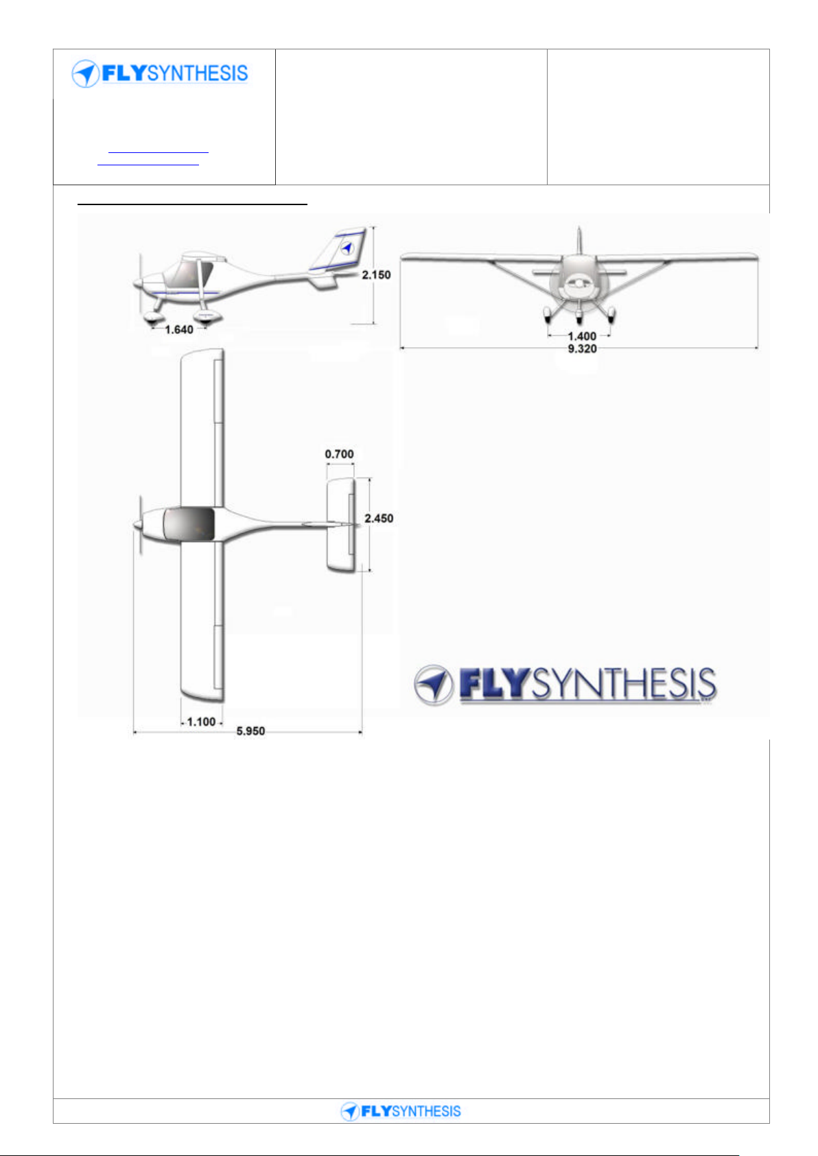
DIMENSIONS (valid for Rotax 912 UL and Jabiru 2200 engines)
General
Wing span: 9.300 m
Length: 5.950 m
Height: 2.150 m
Wing
Surface: 10.250 m2
Wing chord: 1.100 m
Wing load: 44.500 kg/m2
Flap
Surface: 0.620 m2
Page 9

Identification: POH_SS_LSA Rev.0
Page: 9 of 71
Date: 11/10/07
Issued: M. Fiorindo
Verified: M. Fiorindo
Approved: C. Pinzana
Revision Description:
New manual issue
Pilot Operating Handbook and
Training Manual
FLY SYNTHESIS
STORCH S 500 LSA
(for Rotax 912 UL and
Jabiru 2200 engines versions)
Provincial Road n.78 Km 12.150
33050 Mortegliano (UD) – Italy
Tel. +39.(0)432.992482 – +39.(0)432.993557
Fax +39.(0)432.931280
Sito web: www.flysynthesis.com
e-mail: info@flysynthesis.com
Span: 2.230 m
Chord: 0.280 m
Travel: 0° - 40°
Aileron
Surface: 0.410 m2
Span: 1.650 m
Chord: 0.250 m
Travel: down 20° / up 30°
Stabilator
Surface: 1.650 m2
Span: 2.450 m
Chord: 0.700 m
Travel: down 11° / up 16°
Vertical fin (with rudder)
Surface: 1.120 m2
Height: 1.280 m
Mean chord: 1.930 m
Rudder
Surface: 0.600 m2
Height: 1.200 m
Mean chord: 0.480 m
Travel: +/-22°
WEIGHTS
Rotax 912 UL Jabiru 2200
Empty weight 300 kg 297 kg
Maximum allowed weight in baggage compartment 12 kg 12 kg
Maximum Take Off Weight 500 kg 500 kg
Minimum Pilot Weight 55 kg 55 kg
LANDING GEAR (valid for Rotax 912 UL and Jabiru 2200 engines)
Type: Tricycle type landing gear with dampened nose wheel
Main gear track: 1.640 m
Wheelbase: 1.340 m
Tyre: Main: 4.00x6"
Nose wheel: 4.00x4"
Tyre pressure: Main: 2.2 - 2.4 bar
Nose wheel: 1.8 bar
Brakes: Main wheels hydraulic disc.
FUEL SYSTEM (valid for Rotax 912 UL and Jabiru 2200 engines)
Type: Two lines with mechanical and auxiliary eletric fuel pump
Fuel plant draining system and return line system in the left tank
Refueling by the fuel filler located on the upper layer of the wings
Page 10

Identification: POH_SS_LSA Rev.0
Page: 10 of 71
Date: 11/10/07
Issued: M. Fiorindo
Verified: M. Fiorindo
Approved: C. Pinzana
Revision Description:
New manual issue
Pilot Operating Handbook and
Training Manual
FLY SYNTHESIS
STORCH S 500 LSA
(for Rotax 912 UL and
Jabiru 2200 engines versions)
Provincial Road n.78 Km 12.150
33050 Mortegliano (UD) – Italy
Tel. +39.(0)432.992482 – +39.(0)432.993557
Fax +39.(0)432.931280
Sito web: www.flysynthesis.com
e-mail: info@flysynthesis.com
Tanks: Two integrated tanks in glass fibers with 45 liters of capacity for
each tank
Fuel tank caps
Non-usable fuel 2 liters for each tank
Fuel filter: Gascolator on firewall, entry fuel line filtered.
Fuel specification
Rotax 912ULS Premium Automotive Unleaded fuel min 95Ron.
Jabiru 2200A Avgas 100LL.
ELETRIC SYSTEM (valid for Rotax 912 UL and Jabiru 2200 engines)
Type: 12 V electrical wiring with starting battery
Electrical wiring protected with fuses or circuit breakers
External rectifier-regulator
POWERPLANT
Engine: Rotax 912 UL
Type: 4 strokes, 4 cylinder horizontal opposed, spark ignition engine, liquid
cooled cylinder heads, ram air cooled cylinders, two constant depression
carburettors, mechanical fuel pump, dry sump forced lubrification.
Ignition: Increased electric ignition system HD
Battery: Sealed Lead Acid Battery 12 Volts
Standard propeller: DUC composite three blades propeller, diameter 1670 mm, ground
variable pitch.
DUC composite two blades propeller, diameter 1670 mm, ground
variable pitch
GT-2 wood two blades propeller, diameter 1660 mm, fixed pitch 1450
mm.
___________________________________________________________________________________________________________________________________________________
Engine: Jabiru 2200
Type: 4 strokes, 4 cylinder horizontal opposed, spark ignition engine, ram air
cooled cylinders, 2 carburatori a depressione costante, two constant
depression carburettors, mechanical fuel pump, warm air at carburettor
system.
Ignition: Eletric ignition system
Battery: Sealed Lead Acid Battery 12 Volts
Standard propeller: DUC composite three blades propeller, diameter 1520 mm, ground
variable pitch. DUC composite two blades propeller, diameter 1620 mm,
ground variable pitch
Page 11

Identification: POH_SS_LSA Rev.0
Page: 11 of 71
Date: 11/10/07
Issued: M. Fiorindo
Verified: M. Fiorindo
Approved: C. Pinzana
Revision Description:
New manual issue
Pilot Operating Handbook and
Training Manual
FLY SYNTHESIS
STORCH S 500 LSA
(for Rotax 912 UL and
Jabiru 2200 engines versions)
Provincial Road n.78 Km 12.150
33050 Mortegliano (UD) – Italy
Tel. +39.(0)432.992482 – +39.(0)432.993557
Fax +39.(0)432.931280
Sito web: www.flysynthesis.com
e-mail: info@flysynthesis.com
GT-2 wood two blades propeller, diameter 1510/1520/1570 mm, fixed
pitch 1050/1000 mm.
Other propeller types as approved by the manufacturer and listed in appendix C of the
maintenance manual. (Applicable to both engines)
INSTRUMENTS (valid for Rotax 912 ULS and Jabiru 2200 engines)
Standard instruments: air speed indicator, altimeter, vertical speed indicator, magnetic
compass, bank indicator, flap angular range indicator, two low
fuel level amber lamp, CHT, EGT, RPM, oil temperature indicator,
oil pressure indicator, fuel pressure indicator, engine run time
indicator, 12 V aux socket.
OTHER STANDARD EQUIPMENTS (valid for Rotax 912 UL and Jabiru 2200 engines)
Main wheels and nose wheel fairings, main legs and nose camper aerodynamic fairing, four
points safety belts, electric flap system (travel: 0° - 40°), manual trim regulation system, full
moquette cabin covering, baggage compartment with baggage net.
Page 12
Identification: POH_SS_LSA Rev.0
Page: 12 of 71
Date: 11/10/07
Issued: M. Fiorindo
Verified: M. Fiorindo
Approved: C. Pinzana
Revision Description:
New manual issue
Pilot Operating Handbook and
Training Manual
FLY SYNTHESIS
STORCH S 500 LSA
(for Rotax 912 UL and
Jabiru 2200 engines versions)
Provincial Road n.78 Km 12.150
33050 Mortegliano (UD) – Italy
Tel. +39.(0)432.992482 – +39.(0)432.993557
Fax +39.(0)432.931280
Sito web: www.flysynthesis.com
e-mail: info@flysynthesis.com
1.4 AIRCRAFT THREE VIEWS
Page 13
Identification: POH_SS_LSA Rev.0
Page: 13 of 71
Date: 11/10/07
Issued: M. Fiorindo
Verified: M. Fiorindo
Approved: C. Pinzana
Revision Description:
New manual issue
Pilot Operating Handbook and
Training Manual
FLY SYNTHESIS
STORCH S 500 LSA
(for Rotax 912 UL and
Jabiru 2200 engines versions)
Provincial Road n.78 Km 12.150
33050 Mortegliano (UD) – Italy
Tel. +39.(0)432.992482 – +39.(0)432.993557
Fax +39.(0)432.931280
Sito web: www.flysynthesis.com
e-mail: info@flysynthesis.com
SECTION 2
Limitations
Title Page
2.1 Introduction 14
2.2 Airspeed limitations 14
2.3 Anemometers marking 14
2.4 Powerplant and propeller limitations 15
2.5 Powerplant instruments marking 15
2.6 Weight limitations 16
2.7 Center of gravity limitations 16
2.8 Manoeuvre limitations 16
2.9 Load factor limitations 17
2.10 Crew 17
2.11 Placards 17
Page 14
Identification: POH_SS_LSA Rev.0
Page: 14 of 71
Date: 11/10/07
Issued: M. Fiorindo
Verified: M. Fiorindo
Approved: C. Pinzana
Revision Description:
New manual issue
Pilot Operating Handbook and
Training Manual
FLY SYNTHESIS
STORCH S 500 LSA
(for Rotax 912 UL and
Jabiru 2200 engines versions)
Provincial Road n.78 Km 12.150
33050 Mortegliano (UD) – Italy
Tel. +39.(0)432.992482 – +39.(0)432.993557
Fax +39.(0)432.931280
Sito web: www.flysynthesis.com
e-mail: info@flysynthesis.com
Speed
Rotax
912 ULS
IAS
Jabiru
2200
IAS
Notes
Vne
Never Exceed speed
220 km/h
118 KTS
220 km/h
118 KTS
Never exceed this speed in every
condition or configuration
Vmo
Maximum Structural
Cruising Speed
160 km/h
86 KTS
160 km/h
86 KTS
Never exceed this speed in
turbolent air condition
Va
Manoeuvring speed
130 km/h
70 KTS
130 km/h
70 KTS
Do not use full stick and full rudder
deflections above this speed
Vfe
Maximum speed with full
flaps
105 km/h
57 KTS
105 km/h
57 KTS
Do not exceed this speed with flap
extended
Vs
Stall speed without flap
65 km/h
35 KTS
65 km/h
35 KTS
Do not descende this speed without
flap to avoid undesired stall
conditions
Vs1
Stall speed in take off
position (15°)
63 km/h
34 KTS
63 km/h
34 KTS
Do not descende this speed with
flap in take off position to avoid
undesired stall conditions
Vso
Stall speed in landing
position - full flap (40°)
59 km/h
32 KTS
59 km/h
32 KTS
Do not descende this speed with
flap in landing position to avoid
undesired stall conditions
Marking
Speed range (IAS)
Definition
White arc
[Vs0 - Vfe] 59 - 105 km/h
[Vs0 - Vfe] 32 - 57 KTS
Speed range where flap may be extended
Green arc
[Vs - Vmo] 65 - 160 km/h
[Vs - Vmo] 35 - 86 KTS
Speed range of normal operation
Yellow arc
[Vmo- Vne] 160 - 220 km/h
[Vmo- Vne] 86 - 118 KTS
Manoeuvre the aircraft with great caution
Red line
[Vne] 220 km/h
[Vne] 118 KTS
Maximum speed allowed
2.1 INTRODUCTION
This section contains the operational limitations and the instruments marking for use in
safety condition the aircraft, the engine, the equipments and standard plant. The limitations
of speed are been calculated following the BCAR-S rules, the structures are been tested
following the same rules.
2.2 AIRSPEED LIMITATIONS
2.3 ANEMOMETERS MARKING
(valid for Rotax 912 UL and Jabiru 2200 engines)
Page 15
Identification: POH_SS_LSA Rev.0
Page: 15 of 71
Date: 11/10/07
Issued: M. Fiorindo
Verified: M. Fiorindo
Approved: C. Pinzana
Revision Description:
New manual issue
Pilot Operating Handbook and
Training Manual
FLY SYNTHESIS
STORCH S 500 LSA
(for Rotax 912 UL and
Jabiru 2200 engines versions)
Provincial Road n.78 Km 12.150
33050 Mortegliano (UD) – Italy
Tel. +39.(0)432.992482 – +39.(0)432.993557
Fax +39.(0)432.931280
Sito web: www.flysynthesis.com
e-mail: info@flysynthesis.com
Strumento
Red line
Inf. limit
Inf. yellow
arc -Caution
Green arc-normal
operations
Sup. yellow
arc -Caution
Red line
Sup. limit
RPM indicator
n/a
n/a
1.400 - 5.500 rpm
5.500 - 5.800 rpm
5.800 rpm
Fuel pressure gauge
0.15 bar
n/a
0.15 - 0.4 bar
n/a
0.4 bar
Oil pressare gauge
0.8 bar
0.8 - 2 rpm
2 - 5 bar
5 - 7 rpm
7 bar
Oil temp. gauge
50°C
50° - 90°C
90° - 100°C
110° - 140°C
140°C
CHT
50°C
n/a
50° - 100 °C
110° - 150°C
150°C
Strumento
Red line
Inf. limit
Inf. yellow
arc -Caution
Green arc-normal
operations
Sup. yellow
arc -Caution
Red line
Sup. limit
RPM indicator
n/a
n/a
900 - 3.300 rpm
n/a
3.300 rpm
Fuel pressure
gauge
0.05 bar
n/a
0.05 - 0.2 bar
n/a
0.2 bar
Oil pressare gauge
0.8 bar
n/a
2.2 - 5.25 bar
n/a
5.25 bar
Oil temp. gauge
15°C
15° - 80°C
80° - 100°C
100° - 118°C
118°C
CHT
50°C
n/a
50° - 180 °C
180° - 200°C
200°C
EGT
Below 70% of power
Above 70% of power
680° - 750°C
640° - 780°C
2.4 POWERPLANT AND PROPELLER LIMITATIONS
(Refer always to Rotax's or Jabiru operator manual)
Engine manufacturer: Rotax Jabiru Aircraft
Engine model: 912 UL 2200
Maximum take off power: 60 kW 63.4 kW
Maximum continuos power: 58 kW 63.4 kW
Maximum take-off RPM: 5800 rpm 3300 rpm
Maximum continuos RPM: 5500 rpm 3300 rpm
Minimum cylinder head temperature: 150°C 200°C
Maximum oil temperature: 140°C 118°C
Minimum oil pressure: 1.5 bar 2.2 bar
Maximum oil pressure: 7 bar 5.25 bar
Minimum fuel pressure: 0.15 bar 0.05 bar
Maximum fuel pressure: 0.4 bar 0.2 bar
Usable type of fuel: minimum 95 RON Avgas or >95 RON
Usable type of oil: See engine manual specifications
________________________________________________________________________
Propeller manufacturer: DUC Hélices GT Propellers
Propeller model: Carbon three-blades Wood two-blades
Carbon two-blades
Ground variable pitch Fixed pitch
Maximum diameter: 1670 mm 1660 mm
2.5 POWERPLANT INSTRUMENTS MARKING
Rotax 912 UL engine version
Jabiru 2200 engine version
2.6 WEIGHT LIMITATIONS
Page 16
Identification: POH_SS_LSA Rev.0
Page: 16 of 71
Date: 11/10/07
Issued: M. Fiorindo
Verified: M. Fiorindo
Approved: C. Pinzana
Revision Description:
New manual issue
Pilot Operating Handbook and
Training Manual
FLY SYNTHESIS
STORCH S 500 LSA
(for Rotax 912 UL and
Jabiru 2200 engines versions)
Provincial Road n.78 Km 12.150
33050 Mortegliano (UD) – Italy
Tel. +39.(0)432.992482 – +39.(0)432.993557
Fax +39.(0)432.931280
Sito web: www.flysynthesis.com
e-mail: info@flysynthesis.com
Rotax 912 UL Jabiru 2200
Empty weight 300 Kg 297 Kg
Maximum fuel weight 69 Kg 69 Kg
Maximum allowed weight in baggage compartment 12 Kg 12 Kg
Maximum Take Off Weight 500 Kg 500 Kg
2.7 CENTER OF GRAVITY LIMITATIONS
With the purpose to get the best performances of flight and operations in complete safety,
according to the procedures described in this manual, the aircraft must have employed
respecting all the schemes of load and balancing pointed out in the following pages.
Pilot must consider the limit of weighing and all correlated parameters.
Before the delivery of the airplane, centre gravity position and weight of the airplane are
verified.
NOTE: Empty weight & Centre gravity position must be updated after a new weighing, in the
following case:
- Substitution and/or modify of one or plus accessories and equipment;
- After painting or reparations of fusolage.
Weight and Centre Gravity position must be reported after every relief in the weighing report
inside this manual only by authorized personnel.
The location of the CG can be defined by reference to the % MAC.
Maximum anterior limit: 30% M.A.C. correspondent to 330 mms
Maximum back limit: 36% M.A.C. correspondent to 396 mms
For methodology and conditions for weight and balance procedure, see section 6.
2.8 MANOEUVRE LIMITATIONS
All aerobatics maneuvers are prohibited.
The normal flight operations are the followings:
- Every connected manoeuvre to the normal flight operation,
- Stalls, with exclusion of the accelerated stall (superior to 1 g)
- Low speed figure eight, chandelle, turns below 60°
The use of the aircraft has to be conforming with the Rules of the State within it fly.
WARNING
Flight in known icing conditions, snow and heavy rain is prohibited.
The pilot is responsible for determining the airworthiness of the aircraft for each flight
including on board fuel lever verification.
All maneuvers at load factor less than - 0.5 g, must be performed for no longer than 5
seconds.
In single pilot operation, belt and shoulder harness of the vacant seat must be secured to
avoid uncontrolled movement of seat back and belt.
Page 17
Identification: POH_SS_LSA Rev.0
Page: 17 of 71
Date: 11/10/07
Issued: M. Fiorindo
Verified: M. Fiorindo
Approved: C. Pinzana
Revision Description:
New manual issue
Pilot Operating Handbook and
Training Manual
FLY SYNTHESIS
STORCH S 500 LSA
(for Rotax 912 UL and
Jabiru 2200 engines versions)
Provincial Road n.78 Km 12.150
33050 Mortegliano (UD) – Italy
Tel. +39.(0)432.992482 – +39.(0)432.993557
Fax +39.(0)432.931280
Sito web: www.flysynthesis.com
e-mail: info@flysynthesis.com
BAGGAGE COMPARTMENT
Maximum 12 Kg
Evenly distribuited
INFLATE MAIN WHEEL TO
2.2 – 2.4 bar (32 – 35 psi)
INFLATE NOSE WHEEL TO
1.8 bar (26.1 psi)
FUEL CAPACITY 45 LTRS
MINIMUM 95 OCTANE AUTO
FUEL
OR 100 LL AVGAS
2.9 LOAD FACTOR LIMITATIONS
The load factors limit used for the calculation of the structures conform with CS VLA rules:
Flap retracted Flap extendeed
- Maximum positive load factor 4.0 (+) - Maximum positive load factor 2.0 (+)
- Maximum negative load factor 2.0 (-) - Maximum negative load factor 0.0 (+)
2.10 CREW
The minimum crew for flight operations is a person. The owner can choose the place of
pilotage to the right or to the left. The maximum number of people permitted on board is two.
2.11 PLACARDS
The following placards are to be located and visible to the pilot where an inspection or
function is relevant and required in the designated area.
Located on the Instrument panel
WARNING
THIS AIRCRAFT WAS MANUFACTURED IN ACCORDANCE WITH LIGHT SPORT AIRCRAFT
AIRWORTHINESS STANDARDS AND DOES NOT CONFORM TO STANDARD CATEGORY
Located on Nose Leg fairing Located on both Main Leg fairing
Located next to fuel each filler cap Located in baggage compartment
AIRWORTHINESS REQUIREMENTS.
Page 18
Identification: POH_SS_LSA Rev.0
Page: 18 of 71
Date: 11/10/07
Issued: M. Fiorindo
Verified: M. Fiorindo
Approved: C. Pinzana
Revision Description:
New manual issue
Pilot Operating Handbook and
Training Manual
FLY SYNTHESIS
STORCH S 500 LSA
(for Rotax 912 UL and
Jabiru 2200 engines versions)
Provincial Road n.78 Km 12.150
33050 Mortegliano (UD) – Italy
Tel. +39.(0)432.992482 – +39.(0)432.993557
Fax +39.(0)432.931280
Sito web: www.flysynthesis.com
e-mail: info@flysynthesis.com
STORCH S 500 LSA
Speed: KTS Weight: Kg
Vne (Not Exceeded) 118 Maximum Take-off 500
Vmo (Max Operating) 86 Empty Weight 300
Va (Min Maneuvering) 70 Minimum Pilot 55
Vfe (Max Full Flap) 57 Maximum Pilot +
Vs (Stall) 35 passenger 180
Vso (Stall with flap) 32
AEROBATIC MANOEUVRES AND
SPINS ARE PROHIBITED
AUXHILARY
RE FUELING POINT
AUXHILARY
FUEL DRAIN
STORCH 550 LSA DATA PLATE
Aircraft s/n __________ Fusolage s/n __________
Date of Manufacture ____________________
Engine Type ____________________
Engine s/n ____________________
Propeller type ____________________
Propeller s/n ____________________
Hub s/n ____________________
Located on fuselage next to fuel refill tap Located on fuselage next to fuel drain tap
Located in baggage
compartment
Located in baggage
compartment
Located on internal and external side of doors
Page 19

Identification: POH_SS_LSA Rev.0
Page: 19 of 71
Date: 11/10/07
Issued: M. Fiorindo
Verified: M. Fiorindo
Approved: C. Pinzana
Revision Description:
New manual issue
Pilot Operating Handbook and
Training Manual
FLY SYNTHESIS
STORCH S 500 LSA
(for Rotax 912 UL and
Jabiru 2200 engines versions)
Provincial Road n.78 Km 12.150
33050 Mortegliano (UD) – Italy
Tel. +39.(0)432.992482 – +39.(0)432.993557
Fax +39.(0)432.931280
Sito web: www.flysynthesis.com
e-mail: info@flysynthesis.com
SECTION 3
Emergency procedures
Title Page
3.1 Introduction 20
3.2 Ground emergency procedures 20
3.3 Take off emergency procedures 20
3.4 During flight emergency procedures 21
3.5 Electrical wiring failure 22
3.6 Landing emergency procedures 23
3.7 Opening parachute procedure 24
3.8 Other emergency 25
Page 20
Identification: POH_SS_LSA Rev.0
Page: 20 of 71
Date: 11/10/07
Issued: M. Fiorindo
Verified: M. Fiorindo
Approved: C. Pinzana
Revision Description:
New manual issue
Pilot Operating Handbook and
Training Manual
FLY SYNTHESIS
STORCH S 500 LSA
(for Rotax 912 UL and
Jabiru 2200 engines versions)
Provincial Road n.78 Km 12.150
33050 Mortegliano (UD) – Italy
Tel. +39.(0)432.992482 – +39.(0)432.993557
Fax +39.(0)432.931280
Sito web: www.flysynthesis.com
e-mail: info@flysynthesis.com
3.1 INTRODUCTION
An emergency situation is extremely rare; even so, the pilot responsible for the aircraft
should meticulously carry out daily pre-flight controls checks. A safe airworthy aircraft should
be maintained according to the requirements of the accompanying maintenance manual.
This section contains the recommended procedures should an emergency arise. It is
strongly advised that Pilots become familiar with these procedures.
3.2 GROUND EMERGENCY PROCEDEDURES
ENGINE ON FIRE
1. Fuel tank faucet - Close
2. Electric fuel pump - Off
3. Cabin heating - Off
4. Throttle - All forward
5. Master switch - OFF
6. Ignition magnets key - OFF
7. Get out of aircraft immediatly
8. If possible, use an extinguisher to extinguish the fire.
WARNING: Don’t remove the engine cowling until the complete extinction of the fire.
Don't use water to extinguish the fire.
3.3 TAKE OFF EMERGENCY PROCEDURES
TAKE OFF INTERRUPTION (during take off run)
1. Throttle - All rearward (reduce to minimum RPM)
2. Brakes - Brake and avoiding skidding the wheels
3. Flap - Retract
4. Ignition magnets key - OFF
5. Master switch - OFF
6. Fuel tank faucet - OFF
ENGINE FAILURE DURING TAKE OFF (after rotation - below 50 mt)
1. Fuel tank faucet - Close
2. Electric fuel pump - OFF
3. Master switch & ignition magnets key - OFF
4. Safety belts - Tighten well
5. Maintain a linear line of flight, without turning if possible, and if the area allows it, get
ready to a forced landing (see relative paragraph)
ENGINE FAILURE DURING TAKE OFF (during climb)
If the height allows it, proceed in the following way:
1. Best glide speed - (57 KTS)
2. Electric fuel pump - Verify ON
3. Fuel tank faucet - Verify LH tank faucet open
4. Fuel tank level - check fuel quantity
Page 21
Identification: POH_SS_LSA Rev.0
Page: 21 of 71
Date: 11/10/07
Issued: M. Fiorindo
Verified: M. Fiorindo
Approved: C. Pinzana
Revision Description:
New manual issue
Pilot Operating Handbook and
Training Manual
FLY SYNTHESIS
STORCH S 500 LSA
(for Rotax 912 UL and
Jabiru 2200 engines versions)
Provincial Road n.78 Km 12.150
33050 Mortegliano (UD) – Italy
Tel. +39.(0)432.992482 – +39.(0)432.993557
Fax +39.(0)432.931280
Sito web: www.flysynthesis.com
e-mail: info@flysynthesis.com
5. Fuel pressure - Verify within limits
6. Ignition magnets key - Verify ON
7. Throttle - Position warm engine starting
8. Engine start procedure
- If the engine immediately starts up climb to a safe height and land ASAP for a check.
- If the engine doesn't start up prepare for an emergency landing & proceed as follows:
9. Flap - As necessary (30° or 40°)
10. Fuel tank faucet - Close
11. Electric fuel pump - Off
12. Master switch & ignition magnets key - Both Off
WARNING: Land AS SOON AS POSSIBLE in case of fire on board.
- Never perform a 180° turn from too low a height in an effort to return to the runway.
3.4 DURING FLIGHT EMERGENCY PROCEDURES
ENGINE ROUGHNESS/ ENGINE SHUTDOWN
1. Throttle - Check position and friction
2. Check engine instruments - Check parameters
3. Choke lever - OFF / All rearward
4. Fuel tank faucet - Select more full tank
5. Electric fuel pump - ON
6. Fuel pressure - Verify within limits
7. Warm air to carburettors - ON
8. Ignition magnets key - Both / Verify
9. Master switch - Verify / ON
10. Throttle - Position warm engine starting
11. Start - Operate start procedure
12. Check all the engine parameters and land as soon as possible for a check
If the engine doesn't start up choose a proper zone to an emergency landing procedure
ENGINE ON FIRE
1. Fuel tank faucet - Close
2. Electric fuel pump - Off
3. Throttle - All forward
4. Vent system - All closed
5. Cabin heating system - Off
6. Master switch & ignition magneto key - Off
7. Best glide speed - (57 KTS)
9. Landing ASAP
WARNING: Do not attempt to re-start the engine even if engine fire has ceased, but prepare
for an emergency landing.
STALL RECOVERY PROCEDURE
1. Apply full power to reduce the loss of height.
Page 22
Identification: POH_SS_LSA Rev.0
Page: 22 of 71
Date: 11/10/07
Issued: M. Fiorindo
Verified: M. Fiorindo
Approved: C. Pinzana
Revision Description:
New manual issue
Pilot Operating Handbook and
Training Manual
FLY SYNTHESIS
STORCH S 500 LSA
(for Rotax 912 UL and
Jabiru 2200 engines versions)
Provincial Road n.78 Km 12.150
33050 Mortegliano (UD) – Italy
Tel. +39.(0)432.992482 – +39.(0)432.993557
Fax +39.(0)432.931280
Sito web: www.flysynthesis.com
e-mail: info@flysynthesis.com
2. Push softly forward the control stick to eliminate the stall conditions.
NON INTENTIONAL SPIN RECOVERY PROCEDURE
WARNING: don't try to stop the rotation using the opposite ailerons
1. Throttle - At minimum RPM
2. Rudder pedals - All opposed to the sense of rotation
3. Control stick - Neutral, softly to dive
4. When the rotation stops and the aircraft is under control, return to level flight,
WARNING: do not exceed the Vne speed.
3.5 ELETRICAL WIRING FAILURE
GENERATOR WARNING LAMP LIGHTING
1. Voltmeter - Check voltage (if installed)
2. Non essential electric equipment - Off
3. Land ASAP
A fully charged and functional battery should permit the operation of trim, flap and aux
electric fuel pump for about 20 minutes.
OVER VOLTAGE (Voltmeter indication [if installed] over 16 V)
1. Master switch - Off
2. Voltmeter - Verify the decrease of voltage
3. Master switch - On
4. Voltmeter - Verify the increase of voltage (within limits)
If the voltage does not return within limits, proceed as follows
5. All non-essential electrical equipment must be switched off
6. Land ASAP
A fully charged and functional battery should permit the operation of trim, flap and aux
electric fuel pump for about 20 minutes.
LOW VOLTAGE IN FLIGHT
1. Possible causes - Excessive consumption (Too many appliances on)
- Damage of the alternator
- Interrupted fuse
2. Landing ASAP
LOW VOLTAGE ON GROUND
1. RPM - Reduce
2. Navigation and landing lights - Off
3. Voltmeter - Verify within limits
4. If the check has negative result - Shutdown engine
ELECTRICAL WIRING or EQUIPMENT ON FIRE
An electrical fire is recognizable by the distinct odor of burning plastic and white smoke.
1. Master switch - Off
2. Vent systems - All open
3. Cabin heating - Off
Page 23

Identification: POH_SS_LSA Rev.0
Page: 23 of 71
Date: 11/10/07
Issued: M. Fiorindo
Verified: M. Fiorindo
Approved: C. Pinzana
Revision Description:
New manual issue
Pilot Operating Handbook and
Training Manual
FLY SYNTHESIS
STORCH S 500 LSA
(for Rotax 912 UL and
Jabiru 2200 engines versions)
Provincial Road n.78 Km 12.150
33050 Mortegliano (UD) – Italy
Tel. +39.(0)432.992482 – +39.(0)432.993557
Fax +39.(0)432.931280
Sito web: www.flysynthesis.com
e-mail: info@flysynthesis.com
4. Landing ASAP
WARNING: get ready to possibly land without the use of flaps and trim (if electric).
SMOKE ELIMINATION FROM CABIN
1. Vent systems - All open
2. Cabin heating - Off
3. Master switch - Off
4. If the smoke remains dense land immediately.
WARNING: absolutely DO NOT open the canopy.
3.6 LANDING EMERGENCY PROCEDURES
LANDING WITHOUT FLAPS
1. Verify flap/trim circuit breaker is in the ON position.
2. Verify the position of both the flaps visually
With flaps in symmetrical position (both retracted or extracted at the same angle)
3. Try to retract the flaps
4. Verify that there is enough free space from obstacles for a safe landing
5. Land as normal but maintain a landing speed not less than 48 Knots
LANDING WITH A DEFLATED TIRE
1. Landing as per normal condition
2. Before contacting the ground shutdown the engine and turn off electrical equipment.
3. When landing hold-off contact with the ground on the side of the deflated tire for as
long as possible
4. Get ready for a tendency to yaw on the side of the deflate tire
5. Maintain the directionality with rudder and nose wheel steering
6. If nose wheel is deflated maintain backpressure on control stick and keep the nose
wheel in a central position.
FORCED LANDING
1. Best glide speed - (57 KTS)
2. Safety belts - Tighten well
3. Throttle - All rearward (minimum position)
4. Fuel tank faucet - Closed
5. Electric fuel pump. - Off
6. Master switch & ignition magnetos key - Off
CAUTION: Choose a suitable area for an emergency landing.
7. Flap - As necessary
8. Trim - As necessary
9. Final - Check velocity
10. Landing - Check velocity (at least 38 KTS, flap with 40°).
The contact with the ground should happen at the minimum possible speed, maintain lifted
the nose wheel for the longest possible time.
3.7 OPENING PARACHUTE PROCEDURE (IF INSTALLED)
Page 24

Identification: POH_SS_LSA Rev.0
Page: 24 of 71
Date: 11/10/07
Issued: M. Fiorindo
Verified: M. Fiorindo
Approved: C. Pinzana
Revision Description:
New manual issue
Pilot Operating Handbook and
Training Manual
FLY SYNTHESIS
STORCH S 500 LSA
(for Rotax 912 UL and
Jabiru 2200 engines versions)
Provincial Road n.78 Km 12.150
33050 Mortegliano (UD) – Italy
Tel. +39.(0)432.992482 – +39.(0)432.993557
Fax +39.(0)432.931280
Sito web: www.flysynthesis.com
e-mail: info@flysynthesis.com
The emergency parachute is situated in a special container fixed to the inside of the fuselage
and can be seen when the seat is tilted forward. The emergency parachute is fixed to the
aircraft through two Kevlar ropes attached with a special plate to main landing gear strut
bolts. The ropes passing through the internal part of the fuselage and only for the last part
go out untill the canister. The emergency parachute must be used only in case of complete
loss of the control of the aircraft.
Simplified parachute opening procedures
a. Shutdown the engine (magnetos OFF)
b. Pull red handle fixed on the internal wing mount, at least 20 centimeters,
c. Close both fuel faucets
d. Tighten the safety belts
e. Shutdown the electric plant (Master OFF)
f. Protect your body (cover face and keep limbs close)
For further information and notes on function and maintenance, consult the parachute
manual.
Page 25

Identification: POH_SS_LSA Rev.0
Page: 25 of 71
Date: 11/10/07
Issued: M. Fiorindo
Verified: M. Fiorindo
Approved: C. Pinzana
Revision Description:
New manual issue
Pilot Operating Handbook and
Training Manual
FLY SYNTHESIS
STORCH S 500 LSA
(for Rotax 912 UL and
Jabiru 2200 engines versions)
Provincial Road n.78 Km 12.150
33050 Mortegliano (UD) – Italy
Tel. +39.(0)432.992482 – +39.(0)432.993557
Fax +39.(0)432.931280
Sito web: www.flysynthesis.com
e-mail: info@flysynthesis.com
3.8 OTHER EMERGENCY
WARNING: Flight in known icing conditions, snow and heavy rain is prohibited.
If you meet unintentional icing condition during the flight, descend as soon as possible to a
lower height. If the wing leading edge and the stabilator leading edge are covered by ice
formations, remember that stall speed will increase, you will need more engine power to
maintain the same velocity and the maneuverability of the airplane will decrease.
1. Carburetor heating system (if installed) - On
2. Engine RPM - Maintain the maximum continuous engine
power
3. Cabin heating (if installed) - On
4. Move all control surfaces to break potential icing formations.
ICING FORMATIONS ON CARBURETTORS
You can recognize icing formations on carburetors if RPM decreases without moving the
throttle. You can find this phenomenon during a descent with low RPM in a day with a lot of
humidity.
1. Carburetor heating system (if installed) - On
2. Throttle - All forward when RPM starts to increase
3. Carburetor heating system (if installed) - Off
4. Reinstate normal flight conditions
ABNORMAL ENGINE VIBRATIONS
1. Verify the reduction of the vibrations with a reduction of the RPM’s
2. Land as soon as possible
3. Be prepared for a possible engine failure and to commence a forced landing
LANDING WITH BRAKE SYSTEM FAILURE
1. Look for a long grassy runway with absence of obstacles (the grass has a light braking
action)
2. Land with the flaps to the maximum extension and reduce speed to the minimum safe
speed
(After touching the ground)
3. Master switch & ignition magnets key - Off
Page 26

Identification: POH_SS_LSA Rev.0
Page: 26 of 71
Date: 11/10/07
Issued: M. Fiorindo
Verified: M. Fiorindo
Approved: C. Pinzana
Revision Description:
New manual issue
Pilot Operating Handbook and
Training Manual
FLY SYNTHESIS
STORCH S 500 LSA
(for Rotax 912 UL and
Jabiru 2200 engines versions)
Provincial Road n.78 Km 12.150
33050 Mortegliano (UD) – Italy
Tel. +39.(0)432.992482 – +39.(0)432.993557
Fax +39.(0)432.931280
Sito web: www.flysynthesis.com
e-mail: info@flysynthesis.com
SECTION 4
Normal procedures
Title Page
4.1 Introduction 27
4.2 Speed for normal employment 27
4.3 Fuel circuit draining procedure and refuelling operations 27
4.4 Pre-flight Inspection 28
4.5 Flight inside heavy rain 34
Page 27

Identification: POH_SS_LSA Rev.0
Page: 27 of 71
Date: 11/10/07
Issued: M. Fiorindo
Verified: M. Fiorindo
Approved: C. Pinzana
Revision Description:
New manual issue
Pilot Operating Handbook and
Training Manual
FLY SYNTHESIS
STORCH S 500 LSA
(for Rotax 912 UL and
Jabiru 2200 engines versions)
Provincial Road n.78 Km 12.150
33050 Mortegliano (UD) – Italy
Tel. +39.(0)432.992482 – +39.(0)432.993557
Fax +39.(0)432.931280
Sito web: www.flysynthesis.com
e-mail: info@flysynthesis.com
4.1 INTRODUCTION
This section contains the information for normal flight conditions and the checklist to follow
before every flight.
4.2 SPEED FOR NORMAL EMPLOYMENT
Except otherwise suitable, the following speeds refer to the maximum weight of take-off
equal to 500 Kgs and can be used for any inferior weight.
Take off (Flap 15°) Rotax 912 UL and Jabiru 2200
Rotation (40 KTS)
Speed at 50 ft (15 m) obstacle (43 KTS)
Climb, (Flap retracted)
Best angle of climb speed Vx, (5° flap), (51 KTS)
Best rate of climb speed Vy, (0° flap) (67 KTS)
Cruise
Manoeuvring speed (Va) (70 KTS)
Max speed in turbulent air conditions (Vmo) (86 KTS)
Never Exceeding Speed (Vne) (118 KTS)
Landing
Landing approach (57 KTS)
Landing (Flap 40°) (43 KTS)
Touch & go (Maximum power, flap 20°) (46 KTS)
Maximum demonstrated crosswind velocity (15 KTS)
4.3 FUEL CIRCUIT DRAINING PROCEDURE AND REFUELLING OPERATIONS
The fuel circuit draining procedure must be done before the first flight of the day, 10 minutes
after the refueling and if the aircraft has remained parked for more than three hours between
two flights.The fuel circuit draining is performed through the Gascolator filter, situated in the
right lower part of the firewall. Use a transparent and clean container, drain about 80 - 100
cc of fuel. Verify the absence of water.
CAUTION: Perform the fuel circuit draining operation before moving the airplane from the
parking area, to avoid any mixing of condensate water if present on the fuel tanks. If water is
present repeat the fuel circuit draining operation until no water is evident.
Refuel through the fuel filler located on the upper layer of the wings, either by jerry cans or
directly with the gasoline pump. An optional on board electric fuel refilling pump may also be
used.
CAUTION: As the Storch S employs an overflow fuel system that returns excess fuel to the
left hand side tank, it is recommended to always use the left side fuel tank. When the left
tank is near empty use the right tank. To avoid the left tank being overfilled with excess fuel,
frequently alternate the use of both fuel tanks during the cruise. The drawing of fuel
simultaneously from both tanks is not recommended.
Page 28

Identification: POH_SS_LSA Rev.0
Page: 28 of 71
Date: 11/10/07
Issued: M. Fiorindo
Verified: M. Fiorindo
Approved: C. Pinzana
Revision Description:
New manual issue
Pilot Operating Handbook and
Training Manual
FLY SYNTHESIS
STORCH S 500 LSA
(for Rotax 912 UL and
Jabiru 2200 engines versions)
Provincial Road n.78 Km 12.150
33050 Mortegliano (UD) – Italy
Tel. +39.(0)432.992482 – +39.(0)432.993557
Fax +39.(0)432.931280
Sito web: www.flysynthesis.com
e-mail: info@flysynthesis.com
4.4 PRE-FLIGHT INSPECTION
WARNING
Before every flight pilot must check completely the airplane with great attention and
accuracy.
In this section there is a standard pre-flight check list. (Valid for each version)
The pre-flight inspections must be carried out BEFORE EVERY FLIGHT. The pilot in
command is responsible for such inspections. The inspection does not require any special
tooling, although a flashlight can be useful for inspecting dark areas. The purpose of the pre
flight inspection is to verify that there's no evidence of defective parts or problems that can
endanger the safety of flight.
Page 29

Identification: POH_SS_LSA Rev.0
Page: 29 of 71
Date: 11/10/07
Issued: M. Fiorindo
Verified: M. Fiorindo
Approved: C. Pinzana
Revision Description:
New manual issue
Pilot Operating Handbook and
Training Manual
FLY SYNTHESIS
STORCH S 500 LSA
(for Rotax 912 UL and
Jabiru 2200 engines versions)
Provincial Road n.78 Km 12.150
33050 Mortegliano (UD) – Italy
Tel. +39.(0)432.992482 – +39.(0)432.993557
Fax +39.(0)432.931280
Sito web: www.flysynthesis.com
e-mail: info@flysynthesis.com
Remove all the protections
1. Pitot-cover,
2. Wheels stops,
3. Mobile surfaces stops,
4. Windshield covering,
5. Propeller protection,
6. Fuel draining procedure.
Fuselage: left forward side (I)
Fixing axle bolts check correct tightness
Wheel fairing good condition and free space between the wheel and
mounting bracket.
Tire general good condition, inflated correctly
Damper no signs of cracks or distorsion, free movement
Nose wheel support structure no signs of cracks or distorsion.
Alignment check damper-rudder alignment
Fusolage: frontal side (II)
Hub & blades no signs of cracks & clean.
Spinner no signs of cracks, fixed correctly
Fusolage: right forward side (III)
Upper cowling remove
Oil tank check level (for R 912UL remove the cap inside fusolage)
Coolant tank check level (for R 912UL remove the cap inside fusolage)
Radiator and air inlet no signs of cracks, free from obstructions
Engine clean, no oil or refrigerant leakage
Muffler & silencer manifold no signs of cracks, muffler hooked.
Oil and coolant tube system correct functionality, no leakage
Ignition & electric system correct functionality.
Throttle & choke cables free movement
Upper cowling reinstall and check tightness
Right wing: forward side (IV)
Wing surface absence of buckling absence of delaminations
Leading edge absence of delaminations,
Wing strut mount check joint, no signs of cracks
Pitot tube no defects, no blockage and fixed correctly
Right wing: rearward side (V)
Trailing edge absence of delaminations, no signs of cracks
Flap & aileron absence of delaminations, no signs of cracks, free movement, no
excessive play on hinges, fixed correctly, balancing mass fixed correctly,
no signs of lateral movement.
Right main landing gear (VI)
Leg no distorsion, bolts locked, no sign of cracks on the weldings
Brake assembly condition and tightness
Tire general good condition, inflated correctly
Page 30

Identification: POH_SS_LSA Rev.0
Page: 30 of 71
Date: 11/10/07
Issued: M. Fiorindo
Verified: M. Fiorindo
Approved: C. Pinzana
Revision Description:
New manual issue
Pilot Operating Handbook and
Training Manual
FLY SYNTHESIS
STORCH S 500 LSA
(for Rotax 912 UL and
Jabiru 2200 engines versions)
Provincial Road n.78 Km 12.150
33050 Mortegliano (UD) – Italy
Tel. +39.(0)432.992482 – +39.(0)432.993557
Fax +39.(0)432.931280
Sito web: www.flysynthesis.com
e-mail: info@flysynthesis.com
Wheel fairing good condition and free space between the wheel and
mounting bracket.
Fusolage: tail beam (VII)
Tail beam Check joint tail beam/fuselage
Bowden cables Check fixing
Empennage (VIII)
Vertical fin absence of buckling, absence of delaminations, check all rivets
Rudder absence of delaminations, hinges fixed correctly
Lower the tail of the aircraft to lift the nose wheel, check the free movement of the rudder,
any problem on the hinge.
Bowden cables fixed correctly.
Stabilator free movement during all travel range, absence of buckling,
absence of delaminations
Stabilator hinge absence of delaminations, fixed correctly, no play
Balancing mass fixed, no play
Hinge pins fixed correctly
Empennage (IX)
Trim tab free movement, absence of defects, no play.
Stabilator trailing edge absence of delaminations
Fusolage: tail beam (X)
Repeat point (VII)
Left main landing gear (XI)
Repeat point (VI)
Left wing: rearward side (XII)
Repeat point (V)
Left wing: forward side (XIII)
Repeat point (IV)
Check inside cabin (XIV)
Instruments panel fixed correctly, all placards
Master switch ON all instruments ON
Master switch OFF all instruments OFF
Control stick free movement, fixed correctly in its support
Rudder pedals no distorsion, no signs of cracks, correct functionality, fixed
Throttle & choke levers free movement, fixed correctly to the support
Brake lever and parking brake Remove parking brake lock, check lever functionality.
Trim lever check correct functionality
Safety belts check correct functionality
Seats fixed correctly.
Windshield clean, fixed correctly on fusolage
Doors clean, fixed correctly on fusolage, check locked system
correctly in its support, correct functionality of centring
system.
Insert parking brake.
Page 31

Identification: POH_SS_LSA Rev.0
Page: 31 of 71
Date: 11/10/07
Issued: M. Fiorindo
Verified: M. Fiorindo
Approved: C. Pinzana
Revision Description:
New manual issue
Pilot Operating Handbook and
Training Manual
FLY SYNTHESIS
STORCH S 500 LSA
(for Rotax 912 UL and
Jabiru 2200 engines versions)
Provincial Road n.78 Km 12.150
33050 Mortegliano (UD) – Italy
Tel. +39.(0)432.992482 – +39.(0)432.993557
Fax +39.(0)432.931280
Sito web: www.flysynthesis.com
e-mail: info@flysynthesis.com
Luggage secured.
Weight&balance calculated.
BEFORE STARTING ENGINE
Pre-flight check - completed
Seats - adjusted
Safety belts - adjusted and fastened
Doors - closed and locked
Parking brake - ON
Flight controls - full movement and free
Fuel faucets - LH open, RH closed
Trim - Neutral
ENGINE START
Choke lever: Engine cold - ON (all rearward)
Engine warm - OFF (all forward)
Electric fuel pump - ON for 10 sec. then OFF
Throttle - At minimum + 1 cm.
Master key - ON
Generator warning lamp - ON
Ignition magnets switch - each magnetos ON
WARNING: Ensure that the propeller area is clear of any person or object “CLEAR PROP”
Start button - Max 20 sec of starting, rest one minute before retrying
Throttle - 2500 RPM for R912 UL -1200 RPM for Jabiru 2200
Oil pressure - Green arc in 5 sec.
Generator warning lamp - OFF
Electric fuel pump - OFF
BEFORE TAXIING
Electrical system - ON and checked
Navigation instruments - checked
Flaps - Position to take off (15°)
Parking brake - OFF
TAXIING
Brakes - check both operate equally
Flight control - free full movement, stick and pedals
Flight instruments - Check magnetic compass and set altimeter and set gyro’s if fitted.
Throttle - As necessary
Page 32

Identification: POH_SS_LSA Rev.0
Page: 32 of 71
Date: 11/10/07
Issued: M. Fiorindo
Verified: M. Fiorindo
Approved: C. Pinzana
Revision Description:
New manual issue
Pilot Operating Handbook and
Training Manual
FLY SYNTHESIS
STORCH S 500 LSA
(for Rotax 912 UL and
Jabiru 2200 engines versions)
Provincial Road n.78 Km 12.150
33050 Mortegliano (UD) – Italy
Tel. +39.(0)432.992482 – +39.(0)432.993557
Fax +39.(0)432.931280
Sito web: www.flysynthesis.com
e-mail: info@flysynthesis.com
ENGINE CHECK
Rotax 912 UL Jabiru 2200
Parking brake - ON - ON
Fuel tank faucets - LH Open, RH Closed - LH Open, RH Closed
Temperature & pressure - Within limits, in green arc - Within limits, in green arc
Trim - Neutral - Neutral
Flight controls - Free - Free
Check magnets - 3000 RPM maximum decrease - 2000 RPM maximum decrease
300 RPM for each magnets 300 RPM for each magnets
Throttle - All forward, check minimum - All forward, check minimum
5000 RPM +/- 150 for 5 sec. 3000 RPM +/- 150 for 5 sec.
Check minimum RPM - 1400 RPM - 900 RPM
CAUTION: Don't apply full power before 60° C of CHT.
During taxing don’t allow the engine CHT to exceed 135° C
BEFORE TAKE-OFF
Flight controls - Free
Trim - Neutral
Electric fuel pump - ON
Flaps - Set for take-off (15º)
Fuel tank faucets - LH Open, RH Closed
Engine instruments - Within limits
Flight instruments - Check and regulated
Safety belts - adjusted and fastened
Cabin doors - check both locks are engaged and locked
Parking brake - OFF
TAKE-OFF
Aircraft - Align with runway
Throttle lever - Full open smoothly
At (40 KTS) - Rotation
Warning: for a take off from short runway with an obstable of 15 m, use flap with 20°.
- Rotation - (40 KTS)
- Climb speed - (48 KTS) (Vx)
At an altitude of 100 m (300 ft), if a steep climb is necessary to clear obstacles
Flaps - Up
Trim - As necessary
Speed - Vx (flap 5°) or Vy (flap 0°)
Throttle - As necessary
Electric fuel pump - Off
Note : Don't maintain the flaps extendeed with speed higher than (57 KTS) (Vfe).
Page 33

Identification: POH_SS_LSA Rev.0
Page: 33 of 71
Date: 11/10/07
Issued: M. Fiorindo
Verified: M. Fiorindo
Approved: C. Pinzana
Revision Description:
New manual issue
Pilot Operating Handbook and
Training Manual
FLY SYNTHESIS
STORCH S 500 LSA
(for Rotax 912 UL and
Jabiru 2200 engines versions)
Provincial Road n.78 Km 12.150
33050 Mortegliano (UD) – Italy
Tel. +39.(0)432.992482 – +39.(0)432.993557
Fax +39.(0)432.931280
Sito web: www.flysynthesis.com
e-mail: info@flysynthesis.com
CLIMB
Rotax 912 UL Jabiru 2200
Engine RPM - 5000 RPM. - 3000 RPM.
Engine instruments - Within limits - Within limits
Trim - As necessary - As necessary
CRUISE
Rotax 912 UL Jabiru 2200
Throttle - As necessary - As necessary
Engine RPM - Max continuos power 5500 rpm - Max continuos power 3300 rpm
Engine instruments - Within limits - Within limits
WARNING
Check frequently engine instruments, do not overcome limits. Check fuel tank level.
DESCENT
Altimeter - Setting
Warm air at carburetto system - As necessary
Throttle - As necessary
Trim - As necessary
Engine instruments - Within limits
LANDING
Speed - (57 KTS)
Flap - As necessary
Trim - As necessary
Throttle - As necessary
Electric fuel pump - ON
Parking brake check (see note b) - Check
Final Approach speed - (48 KTS)
Touch down speed - (40 KTS)
NOTE:
a) In condition of strong lateral wind or in presence of wind-shear, increase the landing
speed at least (5 KTS)
b) Before landing check brake system pressure by operating the brake lever a couple of
times if the braking system is serviceable you should feel the resistance when pressure is
applied.
TOUCH & GO
Throttle - All forward
Trim - As necessary
Flap - 15°
Speed - Vx (flap 5°) o Vy (flap 0°)
If you touch the ground repeat take off procedure.
Page 34

Identification: POH_SS_LSA Rev.0
Page: 34 of 71
Date: 11/10/07
Issued: M. Fiorindo
Verified: M. Fiorindo
Approved: C. Pinzana
Revision Description:
New manual issue
Pilot Operating Handbook and
Training Manual
FLY SYNTHESIS
STORCH S 500 LSA
(for Rotax 912 UL and
Jabiru 2200 engines versions)
Provincial Road n.78 Km 12.150
33050 Mortegliano (UD) – Italy
Tel. +39.(0)432.992482 – +39.(0)432.993557
Fax +39.(0)432.931280
Sito web: www.flysynthesis.com
e-mail: info@flysynthesis.com
AFTER LANDING
Throttle - Idle
Flaps - UP
Electric fuel pump - OFF
Brakes - Check functionality with “warm brakes”
ENGINE SHUTDOWN
Throttle - Idle
Parking brakes - ON
Electrical equipment - OFF
Magnetos - OFF (one by one)
Master switch - OFF
Fuel tank faucets - closed
4.5 FLIGHT INSIDE OF HEAVY RAIN
Flying inside heavy rain is forbidden as visibility and performance of the flight is reduced,
however if unavoidable reduce speed to (80 KTS) and remember to increase the landing
speed by at least (5 KTS) with wet wing.
Page 35

Identification: POH_SS_LSA Rev.0
Page: 35 of 71
Date: 11/10/07
Issued: M. Fiorindo
Verified: M. Fiorindo
Approved: C. Pinzana
Revision Description:
New manual issue
Pilot Operating Handbook and
Training Manual
FLY SYNTHESIS
STORCH S 500 LSA
(for Rotax 912 UL and
Jabiru 2200 engines versions)
Provincial Road n.78 Km 12.150
33050 Mortegliano (UD) – Italy
Tel. +39.(0)432.992482 – +39.(0)432.993557
Fax +39.(0)432.931280
Sito web: www.flysynthesis.com
e-mail: info@flysynthesis.com
SECTION 5 - Performances
Title Page
5.1 General informations 36
Page 36

Identification: POH_SS_LSA Rev.0
Page: 36 of 71
Date: 11/10/07
Issued: M. Fiorindo
Verified: M. Fiorindo
Approved: C. Pinzana
Revision Description:
New manual issue
Pilot Operating Handbook and
Training Manual
FLY SYNTHESIS
STORCH S 500 LSA
(for Rotax 912 UL and
Jabiru 2200 engines versions)
Provincial Road n.78 Km 12.150
33050 Mortegliano (UD) – Italy
Tel. +39.(0)432.992482 – +39.(0)432.993557
Fax +39.(0)432.931280
Sito web: www.flysynthesis.com
e-mail: info@flysynthesis.com
5.1 GENERAL INFORMATIONS
This section contains all the performance data required for accurate pre-flight planning.
SCHEME OF TAKE-OFF & LANDING PHASES
Figure 5-1 show the take-off and landing phases and medium value recorded
SPEED CONVERSION (DENSITY ALTITUDE)
The density altitude chart (figure 5-2) is provided to determine the density altitude for outside
air temperature and pressure altitude combinations.
UNIT CONVERSION
Figure 5-3 shows the linear scales for conversion of [Km/h – KTS – m/s].
Figure 5-4 shows the linear scales for conversion of [m/s - feet/min and KTS – m/s].
Figure 5-5 shows the linear scales for conversion of [m –feet].
DEMONSTRATED CROSS WIND COMPONENT
The maximum demonstrated crosswind is 17 KTS
Figure 5-6 shows the RELATIVE WIND DIAGRAM VERSUS WIND COMPONENT
ENVELOPE DIAGRAM
Figure 5.7 shows the envelope diagram.
Page 37

Identification: POH_SS_LSA Rev.0
Page: 37 of 71
Date: 11/10/07
Issued: M. Fiorindo
Verified: M. Fiorindo
Approved: C. Pinzana
Revision Description:
New manual issue
Pilot Operating Handbook and
Training Manual
FLY SYNTHESIS
STORCH S 500 LSA
(for Rotax 912 UL and
Jabiru 2200 engines versions)
Provincial Road n.78 Km 12.150
33050 Mortegliano (UD) – Italy
Tel. +39.(0)432.992482 – +39.(0)432.993557
Fax +39.(0)432.931280
Sito web: www.flysynthesis.com
e-mail: info@flysynthesis.com
Take off run
Take off distance
Take off speed
140 m
250 m
45 Knots
Landing distance
Landing run
Landing speed
200 m
125 m
48 Knots
Note: remember that speed and distances are indicative
Figure 5-1
Page 38

Identification: POH_SS_LSA Rev.0
Page: 38 of 71
Date: 11/10/07
Issued: M. Fiorindo
Verified: M. Fiorindo
Approved: C. Pinzana
Revision Description:
New manual issue
Pilot Operating Handbook and
Training Manual
FLY SYNTHESIS
STORCH S 500 LSA
(for Rotax 912 UL and
Jabiru 2200 engines versions)
Provincial Road n.78 Km 12.150
33050 Mortegliano (UD) – Italy
Tel. +39.(0)432.992482 – +39.(0)432.993557
Fax +39.(0)432.931280
Sito web: www.flysynthesis.com
e-mail: info@flysynthesis.com
SPEED CONVERSION (DENSITY ALTITUDE)
This table help you to calculate the TAS (true airspeed) from the IAS (indicated airspeed)
using the simplified formula:
TAS = IAS*Cor. factor
Figure 5-2
Page 39

Identification: POH_SS_LSA Rev.0
Page: 39 of 71
Date: 11/10/07
Issued: M. Fiorindo
Verified: M. Fiorindo
Approved: C. Pinzana
Revision Description:
New manual issue
Pilot Operating Handbook and
Training Manual
FLY SYNTHESIS
STORCH S 500 LSA
(for Rotax 912 UL and
Jabiru 2200 engines versions)
Provincial Road n.78 Km 12.150
33050 Mortegliano (UD) – Italy
Tel. +39.(0)432.992482 – +39.(0)432.993557
Fax +39.(0)432.931280
Sito web: www.flysynthesis.com
e-mail: info@flysynthesis.com
UNIT CONVERSIONS
Figure 5-3
Page 40

Identification: POH_SS_LSA Rev.0
Page: 40 of 71
Date: 11/10/07
Issued: M. Fiorindo
Verified: M. Fiorindo
Approved: C. Pinzana
Revision Description:
New manual issue
Pilot Operating Handbook and
Training Manual
FLY SYNTHESIS
STORCH S 500 LSA
(for Rotax 912 UL and
Jabiru 2200 engines versions)
Provincial Road n.78 Km 12.150
33050 Mortegliano (UD) – Italy
Tel. +39.(0)432.992482 – +39.(0)432.993557
Fax +39.(0)432.931280
Sito web: www.flysynthesis.com
e-mail: info@flysynthesis.com
Figure 5-4
Page 41

Identification: POH_SS_LSA Rev.0
Page: 41 of 71
Date: 11/10/07
Issued: M. Fiorindo
Verified: M. Fiorindo
Approved: C. Pinzana
Revision Description:
New manual issue
Pilot Operating Handbook and
Training Manual
FLY SYNTHESIS
STORCH S 500 LSA
(for Rotax 912 UL and
Jabiru 2200 engines versions)
Provincial Road n.78 Km 12.150
33050 Mortegliano (UD) – Italy
Tel. +39.(0)432.992482 – +39.(0)432.993557
Fax +39.(0)432.931280
Sito web: www.flysynthesis.com
e-mail: info@flysynthesis.com
Figure 5-5
Page 42

Identification: POH_SS_LSA Rev.0
Page: 42 of 71
Date: 11/10/07
Issued: M. Fiorindo
Verified: M. Fiorindo
Approved: C. Pinzana
Revision Description:
New manual issue
Pilot Operating Handbook and
Training Manual
FLY SYNTHESIS
STORCH S 500 LSA
(for Rotax 912 UL and
Jabiru 2200 engines versions)
Provincial Road n.78 Km 12.150
33050 Mortegliano (UD) – Italy
Tel. +39.(0)432.992482 – +39.(0)432.993557
Fax +39.(0)432.931280
Sito web: www.flysynthesis.com
e-mail: info@flysynthesis.com
CROSS WIND TABLE
Figure 5-6
Page 43

Identification: POH_SS_LSA Rev.0
Page: 43 of 71
Date: 11/10/07
Issued: M. Fiorindo
Verified: M. Fiorindo
Approved: C. Pinzana
Revision Description:
New manual issue
Pilot Operating Handbook and
Training Manual
FLY SYNTHESIS
STORCH S 500 LSA
(for Rotax 912 UL and
Jabiru 2200 engines versions)
Provincial Road n.78 Km 12.150
33050 Mortegliano (UD) – Italy
Tel. +39.(0)432.992482 – +39.(0)432.993557
Fax +39.(0)432.931280
Sito web: www.flysynthesis.com
e-mail: info@flysynthesis.com
Vso
Stall Speed with flap 45°
32 KTS
Vs
Stall Speed without flap
35 KTS
Vfe
Maximum speed with extendeed flap
579 KTS
Va
Maneuvering speed
70 KTS
Vne
Never exceed speed
118 KTS
ENVELOPE DIAGRAM
Page 44

Identification: POH_SS_LSA Rev.0
Page: 44 of 71
Date: 11/10/07
Issued: M. Fiorindo
Verified: M. Fiorindo
Approved: C. Pinzana
Revision Description:
New manual issue
Pilot Operating Handbook and
Training Manual
FLY SYNTHESIS
STORCH S 500 LSA
(for Rotax 912 UL and
Jabiru 2200 engines versions)
Provincial Road n.78 Km 12.150
33050 Mortegliano (UD) – Italy
Tel. +39.(0)432.992482 – +39.(0)432.993557
Fax +39.(0)432.931280
Sito web: www.flysynthesis.com
e-mail: info@flysynthesis.com
SECTION 6
Weight & balance
Title Page
6.1 Introduction 45
6.2 Weighing conditions 45
6.3 Weight & balance report 46
Page 45

Identification: POH_SS_LSA Rev.0
Page: 45 of 71
Date: 11/10/07
Issued: M. Fiorindo
Verified: M. Fiorindo
Approved: C. Pinzana
Revision Description:
New manual issue
Pilot Operating Handbook and
Training Manual
FLY SYNTHESIS
STORCH S 500 LSA
(for Rotax 912 UL and
Jabiru 2200 engines versions)
Provincial Road n.78 Km 12.150
33050 Mortegliano (UD) – Italy
Tel. +39.(0)432.992482 – +39.(0)432.993557
Fax +39.(0)432.931280
Sito web: www.flysynthesis.com
e-mail: info@flysynthesis.com
6.1 INTRODUCTION
This section contains the informations for a correct procedure of weight and balance of the
aircraft.
WARNING: exceeding the Centre of Gravity limits can provoke serious problems of stability
and govern-ability of the aircraft.
6.2 WEIGHING CONDITIONS
For the weighing of the aircraft, the followings conditions apply:
- The equipment installed must be approved by the factory for the aircraft in question.
- Must be included the brake fluid, engine oil, water coolant and the non-usable fuel.
- Must use three independent scales for each tire horizontal plan and of a thread to
lead.
- To determinate the empty weight and the position of the Center of Gravity, the aircraft
must be positioned on three autonomous scales, one for each wheel. It is
fundamental that the longitudinal and lateral axes of the aircraft are both in the same
horizontal plane. You can verify the horizontal datum position when the tail beam side
reaches 4° with reference to ground level, as shown in the figure below.
Using a plum bob mark a line on the ground directly beneath the leading edge of the wing.
This point is your reference datum RD. Measurements are to be taken from this point.
X1 is the distance from nose wheel axle center line to projection of RD.
X2 is the distance from main wheel axle center line to projection of RD.
The standard distance is:
X1 = 880mm (±0.5%)
X2 = 460mm (±0.5%).
Page 46

Identification: POH_SS_LSA Rev.0
Page: 46 of 71
Date: 11/10/07
Issued: M. Fiorindo
Verified: M. Fiorindo
Approved: C. Pinzana
Revision Description:
New manual issue
Pilot Operating Handbook and
Training Manual
FLY SYNTHESIS
STORCH S 500 LSA
(for Rotax 912 UL and
Jabiru 2200 engines versions)
Provincial Road n.78 Km 12.150
33050 Mortegliano (UD) – Italy
Tel. +39.(0)432.992482 – +39.(0)432.993557
Fax +39.(0)432.931280
Sito web: www.flysynthesis.com
e-mail: info@flysynthesis.com
The formula for CG calculation is the following:
Xt = ML / PT . [CG position in mm on the wing chord]
Where:
ML = (P2DX + P2SX) x X2 - P1 x X1
Xt% = (Xt / MAC) x 100 [CG position in percentage to the wing chord]
ML = Empty weight moment
P2DX , P2SX = Weight measured on main wheel
P1 = Weight measured on nose wheel
6.3 WEIGHT & BALANCE REPORT
The first recording of the Weighing Report & the Center of Gravity Position of the aircraft is
taken at the factory before the delivery of the same aircraft. The Factory Weight and
Balance report will accompany the Aircraft on delivery.
Every variation due to the installation of new components or repairs and painting, implicate a
new calculation of the empty weight and the relative positioning of the center of gravity.
Any weight and Balance changes should be recorded into the aircraft log book.
Page 47

Identification: POH_SS_LSA Rev.0
Page: 47 of 71
Date: 11/10/07
Issued: M. Fiorindo
Verified: M. Fiorindo
Approved: C. Pinzana
Revision Description:
New manual issue
Pilot Operating Handbook and
Training Manual
FLY SYNTHESIS
STORCH S 500 LSA
(for Rotax 912 UL and
Jabiru 2200 engines versions)
Provincial Road n.78 Km 12.150
33050 Mortegliano (UD) – Italy
Tel. +39.(0)432.992482 – +39.(0)432.993557
Fax +39.(0)432.931280
Sito web: www.flysynthesis.com
e-mail: info@flysynthesis.com
SECTION 7
Aircraft Ground Handling and Servicing
Title Page
7.1 Aircraft ground movement 48
7.2 Aircraft ground anchorage 48
7.3 Aircraft cleaning 49
7.4 Aircraft servicing 49
Page 48

Identification: POH_SS_LSA Rev.0
Page: 48 of 71
Date: 11/10/07
Issued: M. Fiorindo
Verified: M. Fiorindo
Approved: C. Pinzana
Revision Description:
New manual issue
Pilot Operating Handbook and
Training Manual
FLY SYNTHESIS
STORCH S 500 LSA
(for Rotax 912 UL and
Jabiru 2200 engines versions)
Provincial Road n.78 Km 12.150
33050 Mortegliano (UD) – Italy
Tel. +39.(0)432.992482 – +39.(0)432.993557
Fax +39.(0)432.931280
Sito web: www.flysynthesis.com
e-mail: info@flysynthesis.com
7.1 AIRCRAFT GROUND MOVEMENT
Aircraft ground movement with engine running is as follows:
- Get on board
- Either lock or secure the doors
- Start engine
- Verify the absence of obstacles or people/animals in the aircraft vicinity
- Remove the parking brake
- Use throttle to regulate the advancement speed and use the rudder pedals for steering the
aircraft
- When the aircraft has reached the destination, shut off the engine, operate the parking
brake and leave the aircraft.
WARNING: never leave the aircraft with engine running, this can be fatal both for you and
for other people/animals in the aircraft vicinity.
Aircraft ground movement with engine off is as follows:
- Remove the parking brake
- Take the aircraft for the tail beam and pressing downward to lift the dumper
- Verify the absence of obstacles or people/animals in the aircraft range
- Push or pull the aircraft and direct it using only the principal wheels
- Operate the parking brake
An optional front wheel tow bar is available for aircraft movement.
7.2 AIRCRAFT GROUND ANCHORAGE
Anchorage of the aircraft can be performed by first setting ON the park brake then secure
the ropes around each upper wing strut. When tightening the rope to ground mooring DO
NOT apply too much tension force, a small amount of tension will suffice to secure the
aircraft without risking the potential to stress surfaces inadvertently during heavy wind
conditions. If possible point aircraft into the prevailing wind as this will minimize the potential
for wind cock effect.
CAUTION: It is a good practice to secure the control stick from inadvertent movement by
latching to the seatbelts when the aircraft is left unattended or in windy conditions.
Page 49

Identification: POH_SS_LSA Rev.0
Page: 49 of 71
Date: 11/10/07
Issued: M. Fiorindo
Verified: M. Fiorindo
Approved: C. Pinzana
Revision Description:
New manual issue
Pilot Operating Handbook and
Training Manual
FLY SYNTHESIS
STORCH S 500 LSA
(for Rotax 912 UL and
Jabiru 2200 engines versions)
Provincial Road n.78 Km 12.150
33050 Mortegliano (UD) – Italy
Tel. +39.(0)432.992482 – +39.(0)432.993557
Fax +39.(0)432.931280
Sito web: www.flysynthesis.com
e-mail: info@flysynthesis.com
7.3 AIRCRAFT CLEANING
The aircraft is supplied with a kit for complete cleaning.
The following procedure is suggested for cleaning the aircraft.
- Do not use a pressure cleaner directly on the aircraft, as the gel-coat is hygroscopic.
- Use a micro-fiber cloth and neutral soap to clean the aircraft.
- Avoid water bathing of metallic parts.
- Rinse with a damp and clean micro-fiber cloth.
- Dry excess moisture using a deerskin, natural or synthetic chamois.
- The cockpit can be cleaned with a dry micro-fiber cloth and a vacuum cleaner.
CAUTION: to avoid corrosion problems make sure that the metallic parts are not left damp.
The use of a water dispersant spray and or approved lubricant is advised.
7.4 AIRCRAFT SERVICING
Servicing fuel
- Make sure the plane is set on the parking brake.
- Open the fuel cap.
- Pour in fuel as per specification.
- Check that the amount poured equates to the reading from the dipstick.
- Close the cap and make sure the fuel cap vent is directed to the front.
- Make sure no spilled fuel is left on the plane. Remove if necessary.
Servicing Oil
- Remove top cowling.
- Make sure the ignition and both magnetos are off.
- Turn propeller 5-6 times in the normal direction for flight.
- Open the oil tank cap and check the level of the oil by the dipstick.
- Oil should read within marked limits.
- Add oil if necessary.
- Close the cap.
Servicing Coolant (Rotax engine)
- Remove the top cowling.
- Open the cap of the coolant tank and add coolant to fill up the tank.
- Make sure the ignition and both magnetos are off.
- Turn propeller 5-6 times in the normal direction for flight
- Make sure that no air is inside the cooling system.
- Close the coolant tank cap and if necessary add coolant to the expansion tank.
Page 50

Identification: POH_SS_LSA Rev.0
Page: 50 of 71
Date: 11/10/07
Issued: M. Fiorindo
Verified: M. Fiorindo
Approved: C. Pinzana
Revision Description:
New manual issue
Pilot Operating Handbook and
Training Manual
FLY SYNTHESIS
STORCH S 500 LSA
(for Rotax 912 UL and
Jabiru 2200 engines versions)
Provincial Road n.78 Km 12.150
33050 Mortegliano (UD) – Italy
Tel. +39.(0)432.992482 – +39.(0)432.993557
Fax +39.(0)432.931280
Sito web: www.flysynthesis.com
e-mail: info@flysynthesis.com
NOTE:
_______________________________________ ________________
_______________________________________________________
_______________________________________ ________________
_______________________________________ ________________
_______________________________________ ________________
_______________________________________ ________________
_______________________________________________________
_______________________________________ ________________
_______________________________________ ________________
_______________________________________ ________________
_______________________________________ ________________
_______________________________________ ________________
_______________________________________ ________________
_______________________________________ ________________
_______________________________________ ________________
_______________________________________________________
_______________________________________ ________________
_______________________________________ ________________
_______________________________________ ________________
_______________________________________ ________________
_______________________________________________________
_______________________________________ ________________
_______________________________________ ________________
_______________________________________ ________________
_______________________________________ ________________
_______________________________________ ________________
_______________________________________ ________________
_______________________________________ ________________
_______________________________________ ________________
_______________________________________________________
_______________________________________ ________________
_______________________________________ ________________
_______________________________________ ________________
_______________________________________ ________________
Page 51

Identification: POH_SS_LSA Rev.0
Page: 51 of 71
Date: 11/10/07
Issued: M. Fiorindo
Verified: M. Fiorindo
Approved: C. Pinzana
Revision Description:
New manual issue
Pilot Operating Handbook and
Training Manual
FLY SYNTHESIS
STORCH S 500 LSA
(for Rotax 912 UL and
Jabiru 2200 engines versions)
Provincial Road n.78 Km 12.150
33050 Mortegliano (UD) – Italy
Tel. +39.(0)432.992482 – +39.(0)432.993557
Fax +39.(0)432.931280
Sito web: www.flysynthesis.com
e-mail: info@flysynthesis.com
SECTION 8
Aircraft Check Lists
Title Page
8.1 Aircraft on board check lists 52
8.2 Aircraft ground pre flight check list 56
(NOTE: these pages can be cut out and plasticize)
Page 52

Identification: POH_SS_LSA Rev.0
Page: 52 of 71
Date: 11/10/07
Issued: M. Fiorindo
Verified: M. Fiorindo
Approved: C. Pinzana
Revision Description:
New manual issue
Pilot Operating Handbook and
Training Manual
FLY SYNTHESIS
STORCH S 500 LSA
(for Rotax 912 UL and
Jabiru 2200 engines versions)
Provincial Road n.78 Km 12.150
33050 Mortegliano (UD) – Italy
Tel. +39.(0)432.992482 – +39.(0)432.993557
Fax +39.(0)432.931280
Sito web: www.flysynthesis.com
e-mail: info@flysynthesis.com
Storch S 912 UL - Check list (page 1) Storch S 912 UL
- Check list (page 2)
PRE-FLIGHT CHECK - completed TAXIING
Seats - adjusted Brakes - check both operate equally
Safety belts - adjusted and fastened Flight control - free full movement, stick and pedals
Doors - closed and locked Flight instruments
- Check magnetic compass, gyro's
Parking brake - ON and set altimeter QNH
Flight controls - free and full movement Throttle - As necessary
Fuel faucets - LH open, RH closed
ENGINE CHECK
Trim - Neutral
Fuel tank faucets - LH Open, RH Closed Oil Temp & pressure.
- Within limits, in green arc
Trim - Neutral
ENGINE START Flight controls - Free and full movement
Choke lever: Engine cold - ON (all rearward) Check magnetos - 3000 RPM maximum decrease
Engine warm - OFF (all forward) 300 RPM fo
r each magneto
Electric fuel pump - ON for 10 sec. then OFF Throttle - All forward, check minimum
Throttle - At minimum + 1 cm.
5000 RPM +/- 150 for 5 sec.
Master switch - ON Check minimum RPM
- 1400 RPM
Generator warning lamp - ON
Ignition magnets key - each magnets ON BEFORE TAKE-OFF
Ensure the propeller area is clear of any person or object "CLEAR PROP"
Flight controls - Free
Start procedure - Max 20 sec, pause one Trim - Neutral
minute before retrying Electric fuel pump - ON
Throttle - 1800 RPM Flaps - check for take-off position (15º)
Oil pressure - Green arc in 5 sec. Fuel tank faucets - LH Open, RH Closed
Generator warning lamp - OFF Engine instruments
- Within limits
Electric fuel pump - OFF Flight instruments
- Check and regulated
BEFORE TAXIING
Safety belts - adjusted and fastened
Electrical system - ON and checked Doors - check both locks are engaged.
Navigation instruments - checked
Flaps - Position for take-off (15°) Parking brake - OFF
Parking brake - OFF Ballistic parachute if fitted - Remove safety pin before flight
Page 53

Identification: POH_SS_LSA Rev.0
Page: 53 of 71
Date: 11/10/07
Issued: M. Fiorindo
Verified: M. Fiorindo
Approved: C. Pinzana
Revision Description:
New manual issue
Pilot Operating Handbook and
Training Manual
FLY SYNTHESIS
STORCH S 500 LSA
(for Rotax 912 UL and
Jabiru 2200 engines versions)
Provincial Road n.78 Km 12.150
33050 Mortegliano (UD) – Italy
Tel. +39.(0)432.992482 – +39.(0)432.993557
Fax +39.(0)432.931280
Sito web: www.flysynthesis.com
e-mail: info@flysynthesis.com
Storch S 912 UL - Check list (page 3) Storch S 912 UL
- Check list (page 4)
TAKE-OFF LANDING
Aircraft - Align with runway Speed - (56 KTS)
Throttle lever - Full open smoothly Flap - As necessary
At (40KTS) - Rotation Trim - As necessary
For a take off from short runway with an obstacle of 15 m, use 20 ° flap
Throttle - As necessary
- Rotation - 40 KTS Electric fuel pump - ON
- Climb speed - (Vx) 48 KTS Parking brake check - Check
Flaps - Up Final Approach speed - (48 KTS)
Trim - As necessary Touch down speed - (40 KTS)
Speed - Vx or Vy TOUCH & GO
Throttle - As necessary Throttle - All forward Max power
Electric fuel pump - Off Trim - As necessary
CLIMB Flap - 15°
Engine RPM - 5000 RPM. Speed - Vx o Vy
Engine instruments - Within limits If you touch the ground repeat take off procedure.
Trim - As necessary AFTER LANDING
CRUISE Throttle - Idle
Throttle - As necessary Flaps - UP
Engine RPM - Max continuous power 5500 RPM Electric fuel pump - OFF
Engine instruments - Within limits Brakes - Check functionality
Warning: Check frequently engine instruments, do not exceed limits.
with "warm brakes"
The speeds are only indicative ENGINE SHUTDOWN
Speed (90 KTS) - 4000 rpm Throttle - Idle
Speed (97 KTS) - 4800 rpm Parking brakes - ON
Speed (100 KTS) - 5000 rpm Electrical equipment - OFF
Speed (105 KTS) - 5500 rpm Magnetos -OFF (one by one)
DESCENDING Master switch - OFF
Altimeter - Setting Fuel tank faucets - closed
Carburetor heat - As necessary
Throttle - As necessary
Trim - As necessary
Engine instruments - Within limits
Page 54

Identification: POH_SS_LSA Rev.0
Page: 54 of 71
Date: 11/10/07
Issued: M. Fiorindo
Verified: M. Fiorindo
Approved: C. Pinzana
Revision Description:
New manual issue
Pilot Operating Handbook and
Training Manual
FLY SYNTHESIS
STORCH S 500 LSA
(for Rotax 912 UL and
Jabiru 2200 engines versions)
Provincial Road n.78 Km 12.150
33050 Mortegliano (UD) – Italy
Tel. +39.(0)432.992482 – +39.(0)432.993557
Fax +39.(0)432.931280
Sito web: www.flysynthesis.com
e-mail: info@flysynthesis.com
Storch S Jabiru 2200 - Check list (page 1) Storch S Jabiru 2200 - Check list (page 2)
PRE-FLIGHT CHECK - completed TAXIING
Seats - adjusted Brakes - check both operate equally
Safety belts - adjusted and fastened Flight control - free full movement, stick and pedals
Doors - closed and locked Flight instruments - Check magnetic compass, gyro's
Parking brake - ON
and set altimeter QNH
Flight controls - free and full movement Throttle - As necessary
Fuel faucets - LH open, RH closed
ENGINE CHECK
Trim - Neutral
Fuel tank faucets - LH Open, RH Closed Oil Temp & pressure.
- Within limits, in green arc
Trim - Neutral
ENGINE START Flight controls - Free and full movement
Choke lever: Engine cold - ON (all rearward) Check magnetos - 2000 RPM maximum decrease
Engine warm - OFF (all forward) 300 RPM fo
r each magneto
Electric fuel pump - ON for 10 sec. then OFF Throttle - All forward, check minimum
Throttle - At minimum + 1 cm. 3000 R
PM +/- 150 for 5 sec.
Master switch - ON Check minimum RPM
- 900 RPM
Generator warning lamp - ON
Ignition magnets key - each magnetos ON BEFORE TAKE-OFF
Ensure the propeller area is clear of any person or object "CLEAR PROP"
Flight controls - Free
Start procedure - Max 20 sec, pause one rim - Neutral
minute before retrying Electric fuel pump
- ON
Throttle - 1200 RPM Flaps - check for take-off position (15º)
Oil pressure - Green arc in 5 sec. Fuel tank faucets
- LH Open, RH Closed
Generator warning lamp - OFF Engine instruments
- Within limits
Electric fuel pump - OFF Flight instruments - Check and regulated
BEFORE TAXIING
Safety belts - adjusted and fastened
Electrical system - ON and checked Doors - check both locks are engaged
Navigation instruments - checked
Flaps - Position for take-off (15°) Parking brake - OFF
Parking brake - OFF Ballistic parachute if fitted - Remove safety pin before flight
Page 55

Identification: POH_SS_LSA Rev.0
Page: 55 of 71
Date: 11/10/07
Issued: M. Fiorindo
Verified: M. Fiorindo
Approved: C. Pinzana
Revision Description:
New manual issue
Pilot Operating Handbook and
Training Manual
FLY SYNTHESIS
STORCH S 500 LSA
(for Rotax 912 UL and
Jabiru 2200 engines versions)
Provincial Road n.78 Km 12.150
33050 Mortegliano (UD) – Italy
Tel. +39.(0)432.992482 – +39.(0)432.993557
Fax +39.(0)432.931280
Sito web: www.flysynthesis.com
e-mail: info@flysynthesis.com
Storch S Jabiru 2200 - Check list (page 3) Storch S Jabiru 2200
- Check list (page 4)
TAKE-OFF LAND
ING
Aircraft - Align with runway Speed - (56 KTS)
Throttle lever - Full open smoothly Flap - As necessary
At (40KTS) - Rotation Trim - As necessary
For a take off from short runway with an obstacle of 15 m, use 20 ° flap
Throttle - As necessary
- Rotation - 40 KTS Electric fuel pump - ON
- Climb speed - (Vx) 48 KTS Parking brake check - Check
Flaps - Up Final Approach speed
- (48 KTS)
Trim - As necessary Touch down speed - (40 KTS)
Speed - Vx or Vy TOUCH & GO
Throttle - As necessary Throttle - All forward Max power
Electric fuel pump - Off Trim - As necessary
CLIMB
Flap - 15°
Engine RPM - 3000 RPM. Speed - Vx o Vy
Engine instruments - Within limits If you touch the ground repeat
take off procedure.
Trim - As necessary AFTER LANDING
CRUISE
Throttle - Idle
Throttle - As necessary Flaps - UP
Engine RPM - Max continuous power 5500 RPM Electric fuel pump - OFF
Engine instruments - Within limits Brakes - Check functionality
Warning: Check frequently engine instruments, do not exceed limits.
with "warm brakes"
The speeds are only indicative ENGINE SHUTDOWN
Speed (94 KTS) - 2200 rpm Throttle - Idle
Speed (97 KTS) - 2800 rpm Parking brakes - ON
Speed (100 KTS) - 3000 rpm Electrical equipment - OFF
Speed (105 KTS) - 3300 rpm Magnetos -OFF (one by one)
DESCENDING Master switch - OFF
Altimeter - Setting Fuel tank faucets - closed
Carburetor heat - As necessary
Throttle - As necessary
Trim - As necessary
Engine instruments - Within limits
Page 56

Identification: POH_SS_LSA Rev.0
Page: 56 of 71
Date: 11/10/07
Issued: M. Fiorindo
Verified: M. Fiorindo
Approved: C. Pinzana
Revision Description:
New manual issue
Pilot Operating Handbook and
Training Manual
FLY SYNTHESIS
STORCH S 500 LSA
(for Rotax 912 UL and
Jabiru 2200 engines versions)
Provincial Road n.78 Km 12.150
33050 Mortegliano (UD) – Italy
Tel. +39.(0)432.992482 – +39.(0)432.993557
Fax +39.(0)432.931280
Sito web: www.flysynthesis.com
e-mail: info@flysynthesis.com
Remove all the protections
1. pitot-cover,
2. wheels stops,
3. mobile surfaces stops,
4. windshiel covering,
5. propeller protection
6. fuel draining procedure
Fusolage: left forward side (I)
Fixing axle bolts check correct tightness
Wheel fairing good conditions and free space between the wheel and it.
Tire general good condition, inflated correctly
Damper no signs of cracks or distorsion, free movement
Nose wheel support structure no signs of cracks or distorsion.
Alignment check damper-rudder alignment
Fusolage: frontal side (II)
Hub & blades no signs of cracks & clean.
Spinner no signs of cracks, fixed correctly
Fusolage: right forward side (III)
Upper cowling remove
Oil tank check level (for R 912UL remove the cap inside fusolage)
Coolant tank check level (for R 912UL remove the cap inside fusolage)
Radiator and air inlet no signs of cracks, free from obstructions
Engine clean, no oil or coolant leakage
Muffler & silencer manifold no signs of cracks, muffler hooked.
Oil and coolant tube system correct functionality, no leakage
Ignition & electric system correct functionality.
Throttle & choke cables free movement
Upper cowling reinstall and check tightness
Right wing: forward side (IV)
Wing surface absence of buckling absence of delaminations
Leading edge absence of delaminations,
Wing strut mount check joint, no signs of cracks
Pitot tube no defects, fixed correctly, check tubes joint
Right wing: rearward side (V)
Trailing edge absence of delaminations, no signs of cracks
Flap & aileron absence of delaminations, no signs of cracks, free movement, no excessive play on hinges,
fixed correctly, balancing mass fixed correctly, no signs of lateral movement.
Right main landing gear (VI)
Leg no distorsion, bolts locked, no sign of cracks on the weldings
Brake assembly condition and tightness
Tire general good condition, inflated correctly
Wheel fairing good conditions and free space between the wheel and fairing.
Fusolage: tail beam (VII)
Tail beam Check joint tail beam/fusolage
Bowden cables Check fixing
Page 57

Identification: POH_SS_LSA Rev.0
Page: 57 of 71
Date: 11/10/07
Issued: M. Fiorindo
Verified: M. Fiorindo
Approved: C. Pinzana
Revision Description:
New manual issue
Pilot Operating Handbook and
Training Manual
FLY SYNTHESIS
STORCH S 500 LSA
(for Rotax 912 UL and
Jabiru 2200 engines versions)
Provincial Road n.78 Km 12.150
33050 Mortegliano (UD) – Italy
Tel. +39.(0)432.992482 – +39.(0)432.993557
Fax +39.(0)432.931280
Sito web: www.flysynthesis.com
e-mail: info@flysynthesis.com
Empennage (VIII)
Vertical fin absence of buckling, absence of delaminations, check all rivets
Rudder absence of delaminations, hinges fixed correctly
Lower the tail of the aircraft to lift the nose wheel, check the free movement of the rudder, any problem on the
hinge.
Bowden cables fixed correctly.
Stabilator free movement during all travel range, absence of buckling, absence of delaminations
Stabilator hinge absence of delaminations, fixed correctly, no play
Balancing mass fixed, no play
Hinge pins fixed correctly
Empennage (IX)
Trim tab free movement, absence of defects, no play.
Stabilator trailing edge absence of delaminations
Fusolage: tail beam (X)
Repeat point (VII)
Left main landing gear (XI)
Repeat point (VI)
Left wing: rearward side (XII)
Repeat point (V)
Left wing: forward side (XIII)
Repeat point (IV)
Check inside cabin (XIV)
Instruments panel fixed correctly, all placards
Master switch ON all instruments ON
Master switch OFF all instruments OFF
Control Stick free movement, fixed correctly in its support
Rudder pedals no distorsion, no signs of cracks, correct functionality, fixed correctly in its support, correct
functionality of centring system.
Throttle & choke levers free movement, fixed correctly in the support
Brake lever and parking brake Remove parking brake lock, check lever functionality. Insert parking brake.
Trim lever check correct functionality
Safety belts check correct functionality
Seats fixed correctly.
Windshield clean, fixed correctly on fusolage
Doors clean, fixed correctly on fusolage, check locking system
Luggage secured.
Weight&balance calculated.
Page 58

Identification: POH_SS_LSA Rev.0
Page: 58 of 71
Date: 11/10/07
Issued: M. Fiorindo
Verified: M. Fiorindo
Approved: C. Pinzana
Revision Description:
New manual issue
Pilot Operating Handbook and
Training Manual
FLY SYNTHESIS
STORCH S 500 LSA
(for Rotax 912 UL and
Jabiru 2200 engines versions)
Provincial Road n.78 Km 12.150
33050 Mortegliano (UD) – Italy
Tel. +39.(0)432.992482 – +39.(0)432.993557
Fax +39.(0)432.931280
Sito web: www.flysynthesis.com
e-mail: info@flysynthesis.com
00
11/10/07
Complete manual
revision
M. Fiorindo
M. Fiorindo
C. Pinzana
Num. Date
Description
Issued
Verified
Approved
REVISION
FLY SYNTHESIS
STORCH S 500 LSA
(for Rotax 912 UL and Jabiru 2200 engines versions)
FlySynthesis s.r.l. reserves it to terms of law the exclusive ownership of this manual and also forbids the partial reproduction of it.
TRAINING MANUAL
Page 59

Identification: POH_SS_LSA Rev.0
Page: 59 of 71
Date: 11/10/07
Issued: M. Fiorindo
Verified: M. Fiorindo
Approved: C. Pinzana
Revision Description:
New manual issue
Pilot Operating Handbook and
Training Manual
FLY SYNTHESIS
STORCH S 500 LSA
(for Rotax 912 UL and
Jabiru 2200 engines versions)
Provincial Road n.78 Km 12.150
33050 Mortegliano (UD) – Italy
Tel. +39.(0)432.992482 – +39.(0)432.993557
Fax +39.(0)432.931280
Sito web: www.flysynthesis.com
e-mail: info@flysynthesis.com
Title Section Page
General information 60
Introduction 1 61
Fuel and Fuel/Oil consumption 2 62
Engine controls 3 65
Seat belts 4 65
Cockpit entry and Pilot etiquette 5 65
Flight controls 6 67
Ground handling 7 70
Recommended on board tools 8 71
INDEX
Page 60

Identification: POH_SS_LSA Rev.0
Page: 60 of 71
Date: 11/10/07
Issued: M. Fiorindo
Verified: M. Fiorindo
Approved: C. Pinzana
Revision Description:
New manual issue
Pilot Operating Handbook and
Training Manual
FLY SYNTHESIS
STORCH S 500 LSA
(for Rotax 912 UL and
Jabiru 2200 engines versions)
Provincial Road n.78 Km 12.150
33050 Mortegliano (UD) – Italy
Tel. +39.(0)432.992482 – +39.(0)432.993557
Fax +39.(0)432.931280
Sito web: www.flysynthesis.com
e-mail: info@flysynthesis.com
Title Page
1. Introduction 61
1.1 Notice to operators 61
2. Fuel and Fuel/Oil Consumption 62
2.1 Fuel tank capacity 62
2.2 Re Fueling 63
2.2 Oil 64
3. Engine controls 65
3.1 Engine indicators 65
4. Seat belts 65
5. Cockpit entry and pilot etiquette 65
5.1 Cabin door operation 66
6. Flight controls 67
6.1 Flap system 68
6.2 Landing Gear 68
6.3 Tire pressure 69
6.4 Brake system 69
7. Ground handling 70
7.1 Aircraft tie down 70
8. Recommended on board tools 71
SECTION 1
General information
Page 61

Identification: POH_SS_LSA Rev.0
Page: 61 of 71
Date: 11/10/07
Issued: M. Fiorindo
Verified: M. Fiorindo
Approved: C. Pinzana
Revision Description:
New manual issue
Pilot Operating Handbook and
Training Manual
FLY SYNTHESIS
STORCH S 500 LSA
(for Rotax 912 UL and
Jabiru 2200 engines versions)
Provincial Road n.78 Km 12.150
33050 Mortegliano (UD) – Italy
Tel. +39.(0)432.992482 – +39.(0)432.993557
Fax +39.(0)432.931280
Sito web: www.flysynthesis.com
e-mail: info@flysynthesis.com
1. INTRODUCTION
This Flight Training supplement is designed for maximum utilisation as an operating
guide. This manual is intended to offer further specific detail of relevant information useful
when the Storch S is used as a training platform.
This supplement is not designed as a substitute for adequate and competent flight
instruction, knowledge of current procedures and a sound knowledge of the aircrafts
systems and limitations.
This manual should be read in conjunction with the Pilot Operating Handbook.
The pilot in command is responsible for determining that the aircraft is safe for flight and
for remaining within the operating limitations as outlined by the instrument markings,
placards, operating manual and this flight-training supplement.
1.1 NOTICE TO OPERATORS
1. Unless fitted with the optional flight timer operated by an air switch the standard
(Hobbs) hour meter will run anytime the master key is switched ON.
NOTE: TURN OFF MASTER KEY SWITCH WHEN AIRCRAFT NOT IN USE
When carrying out the pre start check, follow the check list and ensure the time between
“Master on” and “engine start” is minimal.
(a) To reduce the battery drain
(b) To keep the VDO time as close as possible to engine running time.
(c) If the aircraft is fitted with an air switch, the reading obtained from the air
switch clock can be used for purposes of airframe and engine maintenance.
2. The checking of the rudders is NOT to be carried out whilst the aircraft is stationary.
The checking of the rudders should only be carried out while taxiing.
Moving the rudder pedals on any aircraft with nose wheel steering, whilst it is
stationary, will over stress the rudder mechanism.
3. Prior to leaving the aircraft, after the parking check is complete, leave the parking
brake off and turn the fuel cocks OFF
(a) Chock the aircraft as soon as practical to prevent accidental movement.
(b) Prevents hydraulic pressure being trapped in the lines for long periods.
(c) Prevents fuel from transferring across with uneven ground.
Page 62

Identification: POH_SS_LSA Rev.0
Page: 62 of 71
Date: 11/10/07
Issued: M. Fiorindo
Verified: M. Fiorindo
Approved: C. Pinzana
Revision Description:
New manual issue
Pilot Operating Handbook and
Training Manual
FLY SYNTHESIS
STORCH S 500 LSA
(for Rotax 912 UL and
Jabiru 2200 engines versions)
Provincial Road n.78 Km 12.150
33050 Mortegliano (UD) – Italy
Tel. +39.(0)432.992482 – +39.(0)432.993557
Fax +39.(0)432.931280
Sito web: www.flysynthesis.com
e-mail: info@flysynthesis.com
4. Please refrain from placing the headset on the instrument combing panel as it may
scratch the underside of the windscreen. The headset should be placed on
appropriate hooks if available or in the rear baggage compartment.
5. It is not good airmanship to leave the flight controls unrestrained, especially in windy
conditions. Always restrain the control stick by using the seat belt, to reduce any
possibility of damage to the flight control mechanism.
2. FUEL AND FUEL/OIL CONSUMPTION
This section relates to Fuel / Oil consumption, type and capacity.
Rotax 912 UL Jabiru 2200A
Economy cruise 16 Litres p/h N/A
For cruise 18.5 Litres p/h 13 Litres p/h
For takeoff and climb 20 Litres p/h 21 Litres p/h
Rotax Normal Fuel Premium unleaded MOGAS >95 RON
Jabiru Normal Fuel AVGAS 100 LL
Rotax engines NOTE: Due to the higher lead content in AVGAS, the wear of the valve seats,
the deposits in the combustion chamber and lead sediments in the lubrication system will
increase. Therefore only use AVGAS if other fuel types are not available.
For detailed information on the approved fuels, refer to the ROTAX and JABIRU operator’s
manual.
Jabiru recommends using AVGAS 100LL, AVGAS 100/130 and MOGAS with Minimum 95
RON.
Do not use fuel additives such as Octane boosters or MOGAS with any level of added
Alcohol.
2.1 FUEL TANK CAPACITY:
- Fuel tank capacity 2 x 45 L
- Un usable fuel 2 x 2 L
- Usable fuel 86 L
NOTE: It is good practice to allow a minimum of 45 minutes of reserve fuel on board.
Page 63

Identification: POH_SS_LSA Rev.0
Page: 63 of 71
Date: 11/10/07
Issued: M. Fiorindo
Verified: M. Fiorindo
Approved: C. Pinzana
Revision Description:
New manual issue
Pilot Operating Handbook and
Training Manual
FLY SYNTHESIS
STORCH S 500 LSA
(for Rotax 912 UL and
Jabiru 2200 engines versions)
Provincial Road n.78 Km 12.150
33050 Mortegliano (UD) – Italy
Tel. +39.(0)432.992482 – +39.(0)432.993557
Fax +39.(0)432.931280
Sito web: www.flysynthesis.com
e-mail: info@flysynthesis.com
Pic 1 Left & Right Low fuel warning lamps Pic 2 Fuel tank dipstick
2.2 RE FUELING
The Storch S 500 is refuelled by the fuel caps located on top of the port and starboard wing.
Each tank is fitted with a fuel measuring dip stick to determine approximate quantity. In most
cases a ladder may be required for bowser filling.
CAUTION: If an Earth cable is available at the refueling station it must be connected to the
Aircraft earth located at the front nose leg.
If fitted, the (optional) on board electric re fuelling pump can siphon the fuel directly from a
jerry can and supply each tank providing the fuel tap is selected ON for that tank. The
Auxiliary fuel pump switch is located on the central control panel and can be operated with
out the Master switch being on. A fuel hose with built in fuel filter is supplied when this
option is available.
Pic 1 Re fuelling direct from Jerry Can Pic 2 Fuel tank selector Taps
NOTE: Smoking during re fuelling is strictly prohibited. Re fuelling must be done outdoors
and not in aircraft hangars. Clean and wipe up any spilled fuel.
Page 64

Identification: POH_SS_LSA Rev.0
Page: 64 of 71
Date: 11/10/07
Issued: M. Fiorindo
Verified: M. Fiorindo
Approved: C. Pinzana
Revision Description:
New manual issue
Pilot Operating Handbook and
Training Manual
FLY SYNTHESIS
STORCH S 500 LSA
(for Rotax 912 UL and
Jabiru 2200 engines versions)
Provincial Road n.78 Km 12.150
33050 Mortegliano (UD) – Italy
Tel. +39.(0)432.992482 – +39.(0)432.993557
Fax +39.(0)432.931280
Sito web: www.flysynthesis.com
e-mail: info@flysynthesis.com
2.3 Oil
Prior to checking the engine oil level, turn the propeller by hand several times to pump the oil
from the engine in to the oil tank.
This process is finished when air is returning back to the oil tank and can be noticed by a
“murmur” from the open oil tank.
Oil level should be between the min and max mark, but never below the minimum mark.
Prior to longer periods of operation ensure that the oil level is at least up to the mid position.
Oil Quantity Normal Rotax 3.0 liters Jabiru 3.4 liters
Minimum oil consumption 0.1 l/hr 0.1 l/hr
For detailed information on recommended oil grades refer to the ROTAX and JABIRU
operator’s manual.
Recommended engine oils for Rotax engines running on Unleaded Auto Fuel
Oil Capacity: 3.0 Litres
MOBIL 1 (5w- 30) or (15W-50)
SHELL Advance VSX 4 (10W-40) or (15W-50)
SHELL Advance Ultra 4 (10W-40)
VALVOLINE Dura blend Synthetic (10W-40)
PENNZOIL Motorcycle Motor Oil (20W-50)
Recommended engine oils for Rotax engines running on AVGAS fuel
SHELL Advance VSX 4 (10W-40) or (15W-50)
SHELL Formula (10W-30) or (20W-50)
SHELL Formula Synthetic Blend (10W-30)
VALVOLINE Dura blend Synthetic (10W-40)
NOTE: Remeber if using AVGAS in Rotax engine the Engine oil will require more regular oil
changes.
Recommended engine oils for Jabiru 2200A engines running on AVGAS fuel
Oil Capacity: 3.4 Litres
AEROSHELL W100 or equivalent.
Page 65

Identification: POH_SS_LSA Rev.0
Page: 65 of 71
Date: 11/10/07
Issued: M. Fiorindo
Verified: M. Fiorindo
Approved: C. Pinzana
Revision Description:
New manual issue
Pilot Operating Handbook and
Training Manual
FLY SYNTHESIS
STORCH S 500 LSA
(for Rotax 912 UL and
Jabiru 2200 engines versions)
Provincial Road n.78 Km 12.150
33050 Mortegliano (UD) – Italy
Tel. +39.(0)432.992482 – +39.(0)432.993557
Fax +39.(0)432.931280
Sito web: www.flysynthesis.com
e-mail: info@flysynthesis.com
3. ENGINE CONTROLS
Engine power is controlled by a push pull throttle control lever, operating both carburettors
simultaneously. A choke is provided for starting a cold engine. The twin-magneto ignition
system is controlled by the key operated switch.
The electrical bus system is activated by the Master switch and needs to be ON for the
magneto key switch to be operable.
An Electric fuel pump supplies fuel pressure prior to the engine starting and running and is
used as back up for the engine driven fuel pump in case of failure.
3.1 ENGINE INDICATIONS
The rpm indicator indicates engine speed (RPM). This is an electronic unit.
The cylinder head temperature (CHT) indicator shows engine temperature.
The oil pressure indicator indicates oil pressure.
A separate indicator indicates the oil temperature. An Exhaust Gas Temperature system
(EGT) is also installed.
The fuel pressure indicator indicates fuel pressure with the engine pump and/or aux electric
fuel pump in use. This fuel pressure indicator is a mechanical unit.
A standard sealed accumulating hours-meter (Hobbs meter), counts the total time the
ignition key is switched on. An optional air switch may be fitted that accumulates time on an
air switch clock when the aircraft attains a speed greater than 30 knots. The air switch time
can be used for purposes of airframe and engine maintenance.
4. SEAT BELTS AND SEAT ADJUSTMENTS
Pilot and passenger seats are made from a chromemoly steel frame with padded sponge
seat cushions. The seats can be easily removed to enable inspection of the controls below
the seat. Each seat can be adjusted fwd and aft as well as the recline position to suit pilot
and passenger’s size.
WARNING: Never try to change seat adjustment in flight!
Each seat is equipped with safety belts, which are locked together with a bayonet quick
release latching system. The safety belts are attached to the main structure and each can be
adjusted for occupant comfort. Belts should be replaced if frayed, cut, stitching is broken or
latching defective.
5. COCKPIT ENTRY AND PILOT ETIQUETE
Entry into cockpit is achieved by entering rear end first. By placing your bottom on the lower
door sill you are now able to hoist yourself into the cabin seat. Once seated swing one leg at
a time over the control stick so that both feet now reach the pedals. DO NOT Step onto the
wheel fairing in an attempt to hoist your body into the cabin as doing so may damage the
wheel fairing. See pic 1and 2 below.
Page 66

Identification: POH_SS_LSA Rev.0
Page: 66 of 71
Date: 11/10/07
Issued: M. Fiorindo
Verified: M. Fiorindo
Approved: C. Pinzana
Revision Description:
New manual issue
Pilot Operating Handbook and
Training Manual
FLY SYNTHESIS
STORCH S 500 LSA
(for Rotax 912 UL and
Jabiru 2200 engines versions)
Provincial Road n.78 Km 12.150
33050 Mortegliano (UD) – Italy
Tel. +39.(0)432.992482 – +39.(0)432.993557
Fax +39.(0)432.931280
Sito web: www.flysynthesis.com
e-mail: info@flysynthesis.com
Pic 1 Hoisting on board. Pic 2 Do Not use the wheel fairing as a means
of hoisting into the cabin.
5.1 CABIN DOOR OPERATION
The Storch doors are made from composite material and clear Lexan. The gull type doors
are hinged at the top and can be locked in the open position for entry and exit. Doors can be
removed for summertime operation and wind deflectors attached to minimise turbulence
within the cabin.
WARNING: Never try to open the doors during the flight! Ensure they are fully locked.
Pic 1 Door in locked position Pic 2 Door removed and wind deflector installed
Page 67

Identification: POH_SS_LSA Rev.0
Page: 67 of 71
Date: 11/10/07
Issued: M. Fiorindo
Verified: M. Fiorindo
Approved: C. Pinzana
Revision Description:
New manual issue
Pilot Operating Handbook and
Training Manual
FLY SYNTHESIS
STORCH S 500 LSA
(for Rotax 912 UL and
Jabiru 2200 engines versions)
Provincial Road n.78 Km 12.150
33050 Mortegliano (UD) – Italy
Tel. +39.(0)432.992482 – +39.(0)432.993557
Fax +39.(0)432.931280
Sito web: www.flysynthesis.com
e-mail: info@flysynthesis.com
6. FLIGHT CONTROL
The airplane has standard three axis controls, with dual stick and dual rudder pedals.
All control surfaces are made from composite material. The control surfaces are mounted on
metal hinges and in-turn operated by metal mechanisms. All three control surfaces are mass
weight balanced to prevent flutter. The pitch is controlled by the stabilator, commonly known
as flying tail. There is no fixed elevator section and a negatively geared trim tab is used to
position the stabilator in the correct pitch and also to trim the aircraft. The two control sticks
in the cockpit are inter-connected and Bowden type push-pull cable rods transfer the
movement to the stabilator. The mechanical trim is achieved by changing the zero position of
the geared tab. The manual trim lever is positioned centrally above the head of the pilot and
it moves the trim through a push-pull flexible cable, Roll control is by ailerons. Push-pull rods
operate the ailerons. These are differential ailerons where the angular movement up is
greater then the angular movement down. Directional control is by a rudder installed on the
vertical fin stabilizer. Rudder pedal motion is transmitted via Bowden flexible steel cables
rods to the rudder bell-crank. The rudder pedals are connected at the front of the aircraft to
the steerable nose wheel, which completes the rudder control loop. Tensioned shock rope
helps to centralize the rudder and improve pilot's control feel.
CAUTION
Do not operate rudder pedals whilst stationary. Excessive pressure applied to rudder
pedals may result in damage to the rudder control pedal structure.
Pic 1 Trim lever Pic 2 Trim tab (anti servo)
Roll control is by ailerons. Push-pull rods operate the ailerons. These are differential ailerons
where the angular movement up is greater than the angular movement down.
Directional yaw control is by a rudder installed on the vertical fin. Rudder pedal motion is
transmitted via a flexible steel cable to the rudder bell crank.
Page 68

Identification: POH_SS_LSA Rev.0
Page: 68 of 71
Date: 11/10/07
Issued: M. Fiorindo
Verified: M. Fiorindo
Approved: C. Pinzana
Revision Description:
New manual issue
Pilot Operating Handbook and
Training Manual
FLY SYNTHESIS
STORCH S 500 LSA
(for Rotax 912 UL and
Jabiru 2200 engines versions)
Provincial Road n.78 Km 12.150
33050 Mortegliano (UD) – Italy
Tel. +39.(0)432.992482 – +39.(0)432.993557
Fax +39.(0)432.931280
Sito web: www.flysynthesis.com
e-mail: info@flysynthesis.com
6.1 FLAP SYSTEM
The flap surfaces are constructed of composite materials.
Each flap is attached to the wing by 2 hinges. Both flaps are mechanically interconnected.
This is asymmetry protection. See pic 2 below
Flap operation is achieved by a 3-position spring return switch mounted on the central
console. The switch operates an electric motor through a reduction gearbox, located within
the right hand wing. See pic 1 below
The motor, through the reduction gearbox and a screw jack transmits the motion into the
flaps interconnecting torque shafts.
An angular position transducer installed near the gearbox transmits the flap position to the
flap indicator on the instrument panel.
Pic 1 Flap selector switch and Flap Pic 2 Flaps in full flap position
angle indicator
6.2 LANDING GEAR
Main gear track 1.640 m Main wheel – Nose wheel base 1.340 m
The main gear assembly consists of a main spar, made of steel tube and bolted at four
points to the fuselage structure underneath the seating area.
The landing gear struts are made of high strength spring steel and bolted into the gear spar.
Providing they are not bent due to heavy landings can be used indefinitely. Alternatively
Ergal alloy steel landing gear struts are available and have a time limited period of 300
hours. Main gear shock absorption is by the elasticity of the leg. Each wheel of the main
gear is equipped with a disk brake.
Page 69

Identification: POH_SS_LSA Rev.0
Page: 69 of 71
Date: 11/10/07
Issued: M. Fiorindo
Verified: M. Fiorindo
Approved: C. Pinzana
Revision Description:
New manual issue
Pilot Operating Handbook and
Training Manual
FLY SYNTHESIS
STORCH S 500 LSA
(for Rotax 912 UL and
Jabiru 2200 engines versions)
Provincial Road n.78 Km 12.150
33050 Mortegliano (UD) – Italy
Tel. +39.(0)432.992482 – +39.(0)432.993557
Fax +39.(0)432.931280
Sito web: www.flysynthesis.com
e-mail: info@flysynthesis.com
6.3 TIRE PRESSURES
It is essential to maintain your tires in good condition. When checking tire pressure, examine
for tire wear, cuts, bruises and slippage. Remove oil, grease and mud from tires with soap
and water.
NOTE: Recommended tire pressures should be maintained, especially in cold weather. Any
drop in temperature of air inside the tire causes a corresponding drop in tire pressure.
Main wheel tire 4.00x6” or (13x5x6), inflation pressure 2.2 – 2.4 bar (32 – 35 psi)
Large main wheel tire 15x6x6, inflation pressure 2.2 – 2.4 bar (32 – 35 psi)
Nose wheel tire 4.00x4”, (100/75-5) inflation pressure: 1.8 bar (26.1 psi)
NOTE: When doing long distance cross country exercises it would be advisable to carry a
spare tube or puncture repair kit especially if you’re likely to land on rough strips. A minimum
set of tools would also be required for field repairs, see section 8.
6.4 BRAKE SYSTEM
Hydraulically operated disk brakes are installed on each main wheel. Both brakes are
actuated by the one brake lever mounted centrally between the seats. Pulling the brake lever
operates both brakes. The braking force will increase by the same amount of pressure
applied on the brake lever.
The hand brake locking lever is mounted on the main brake lever. Application of the hand
brake is effected by raising the main brake lever and then pushing down the small park lever
to lock in the braking pressure. Once operated the hand brake assures efficient braking for
10 minutes, necessary for a pre-flight engine check or short parking time. See pic 1and 2
below.
Pic 1 Parking brake lever disengaged Pic 2 Parking brake lever engaged
Page 70

Identification: POH_SS_LSA Rev.0
Page: 70 of 71
Date: 11/10/07
Issued: M. Fiorindo
Verified: M. Fiorindo
Approved: C. Pinzana
Revision Description:
New manual issue
Pilot Operating Handbook and
Training Manual
FLY SYNTHESIS
STORCH S 500 LSA
(for Rotax 912 UL and
Jabiru 2200 engines versions)
Provincial Road n.78 Km 12.150
33050 Mortegliano (UD) – Italy
Tel. +39.(0)432.992482 – +39.(0)432.993557
Fax +39.(0)432.931280
Sito web: www.flysynthesis.com
e-mail: info@flysynthesis.com
7. GROUND HANDLING
Aircraft ground movement with engine off is as follows:
- Remove the parking brake if ON.
- Rotating the aircraft is best achieved by holding down the tail beam which will lift the front
wheel off the ground allowing the main wheels to act as a pivot. See pic 1 below
- Moving the aircraft forward or backward is best achieved by applying pressure to the
propeller root nearest the spinner. See pic 2 below. - When the aircraft is in its desired place
operate the parking brake, or if hangared use wheel chocks.
WARNING: DO NOT apply excessive force on the front wheel to achieve steering.
DO NOT press onto the spinner itself.
Pic 1 Push down to lift the front wheel off. Pic 2 Fwd & Aft movement via the prop hub
7.1 AIRCRAFT TIE DOWN
Anchorage of the aircraft can be performed by first setting ON the park brake then secure
the ropes around each upper wing strut. When tightening the rope to ground mooring DO
NOT apply too much tension force, a small amount of tension will suffice to secure the
aircraft without risking the potential to stress surfaces inadvertently during heavy wind
conditions. If possible point aircraft into the prevailing wind as this will minimize the potential
for wind cock effect. See pic 1
CAUTION: It is good practice to secure the control stick from inadvertent movement by
latching to the seatbelts when the aircraft is left unattended or in windy conditions. See Pic 2
Page 71

Identification: POH_SS_LSA Rev.0
Page: 71 of 71
Date: 11/10/07
Issued: M. Fiorindo
Verified: M. Fiorindo
Approved: C. Pinzana
Revision Description:
New manual issue
Pilot Operating Handbook and
Training Manual
FLY SYNTHESIS
STORCH S 500 LSA
(for Rotax 912 UL and
Jabiru 2200 engines versions)
Provincial Road n.78 Km 12.150
33050 Mortegliano (UD) – Italy
Tel. +39.(0)432.992482 – +39.(0)432.993557
Fax +39.(0)432.931280
Sito web: www.flysynthesis.com
e-mail: info@flysynthesis.com
Pic 1 Wing tied down example. Pic 2 Control stick fastened.
8. RECOMMENDED ON BOARD TOOLS
The Storch utilises metric fasteners throughout the aircraft and with a small list of tools most
simple repairs can be carried out in the event of temporary or emergency repairs.
The following tools are suggested to be carried on board when cross country flight or long
distance NAV exercises are intended.
Open end or ring spanners 6mm, 8mm, 10mm, 13mm
Hex key set 4mm - 10mm
Double sided screw driver flat head and Phillips
Shifting spanner up to 20mm opening
Pliers
Tie down kit
Flash light
Puncture repair kit
 Loading...