

Page 1
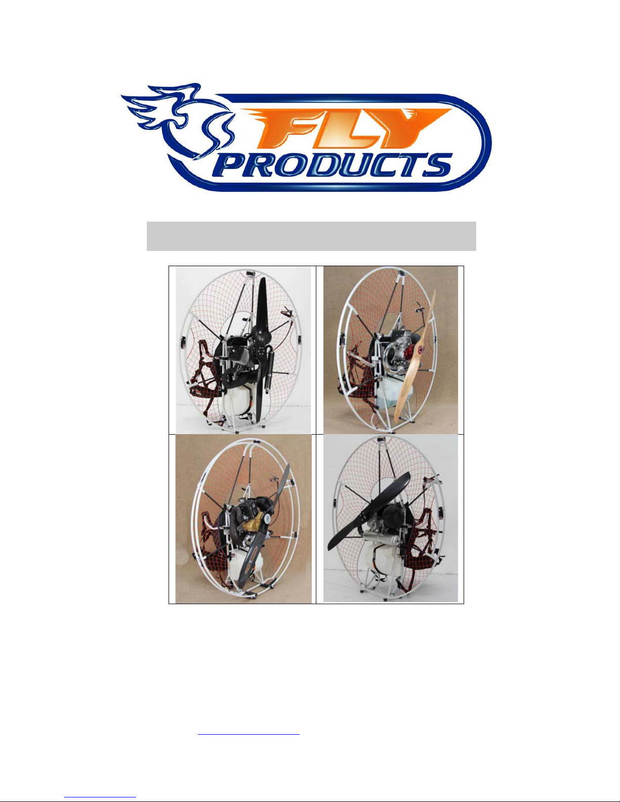
VERSION 1.1 – 01/2013
© Copyright by
FLY
Products s.r.l.
Via Perù n. 30
63013 GROTTAMMARE (AP) - ITALY
tel./fax +39.735.632486
www.flyproducts.com - [email protected]
ASSEMBLY MANUAL
Page 2

ASSEMBLY MANUAL __ REL . 1.1
___________________________________________________________________________
© Copyright by
FLY
PRODUCTS s.r.l. Pag.
2
INDEX
1
FRAME ASSEMBLY
2
HARNESS SIZE ADJUSTMENT
3
FITTING THE HARNESS HIGH ATTACK
4
FITTING THE HARNESS LOW ACTIVE ATTACK (ACTIVE
LOW HANG POINT) OPTIONAL
5
FITTING THE HARNESS FIXED (FIXED HANG POINT)
OPTIONAL
6
PROP MOUNTING
7
MULTIFUNCTION HANDGRIP
8
WARRANTY
Page 3
ASSEMBLY MANUAL __ REL . 1.1
___________________________________________________________________________
© Copyright by
FLY
PRODUCTS s.r.l. Pag.
3
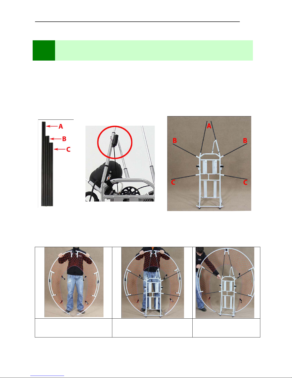
Photo frame Assembly common to paramotors: Thrust, Race c, Kompress, Spri nt,
Jet.
• Step 1: assembling the out er frame
Supports
Starter manual section
(only manual starter)
Support Assembly
Step 2: Assembling the top section of the external frame
Assemble the two semicircles
Assemble the cage from top
grafts
Continue side grafting over
and then the lower teeth on
each side
1
FRAME ASSEMBL Y
Page 4
ASSEMBLY MANUAL __ REL . 1.1
___________________________________________________________________________
© Copyright by
FLY
PRODUCTS s.r.l. Pag.
4
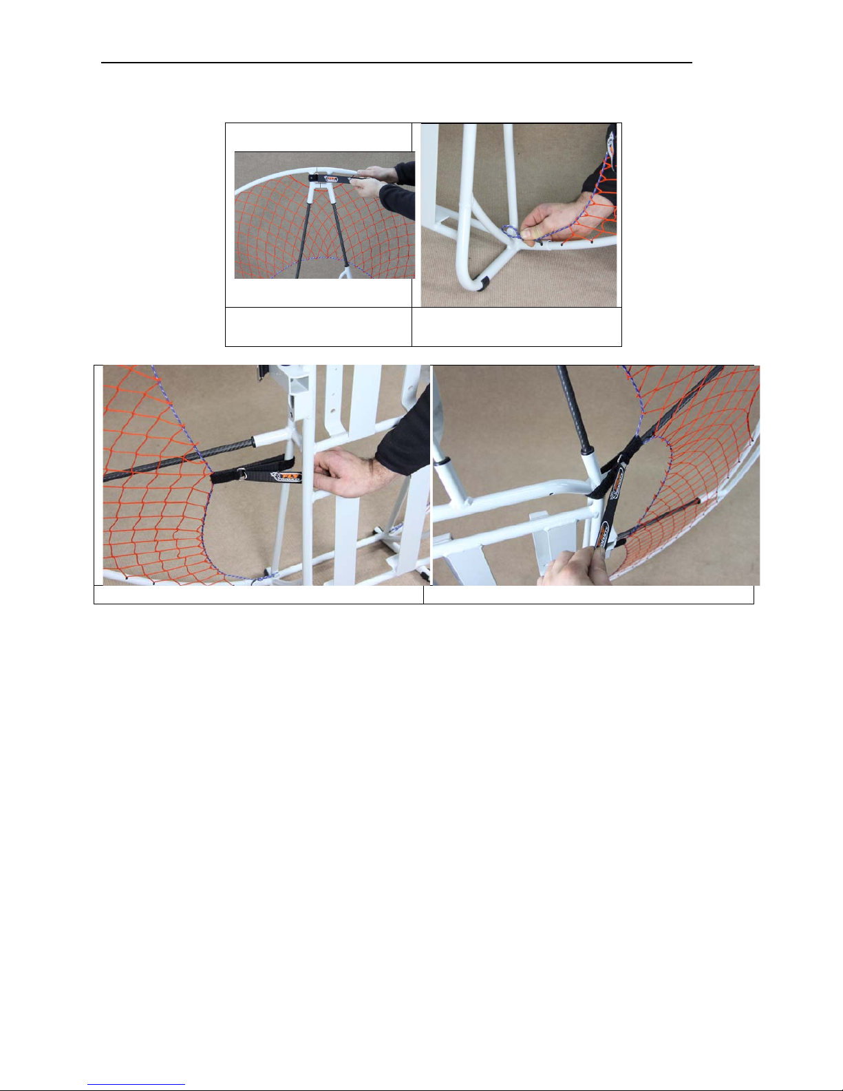
Punto 3 : Bloccaggio dei velcri
Upper Velcro
Hook network cord on both
sides
Tighten the bottom with velcro tape on both sides
Tighten the upper with velcro tape on both sides
Page 5
ASSEMBLY MANUAL __ REL . 1.1
___________________________________________________________________________
© Copyright by
FLY
PRODUCTS s.r.l. Pag.
5
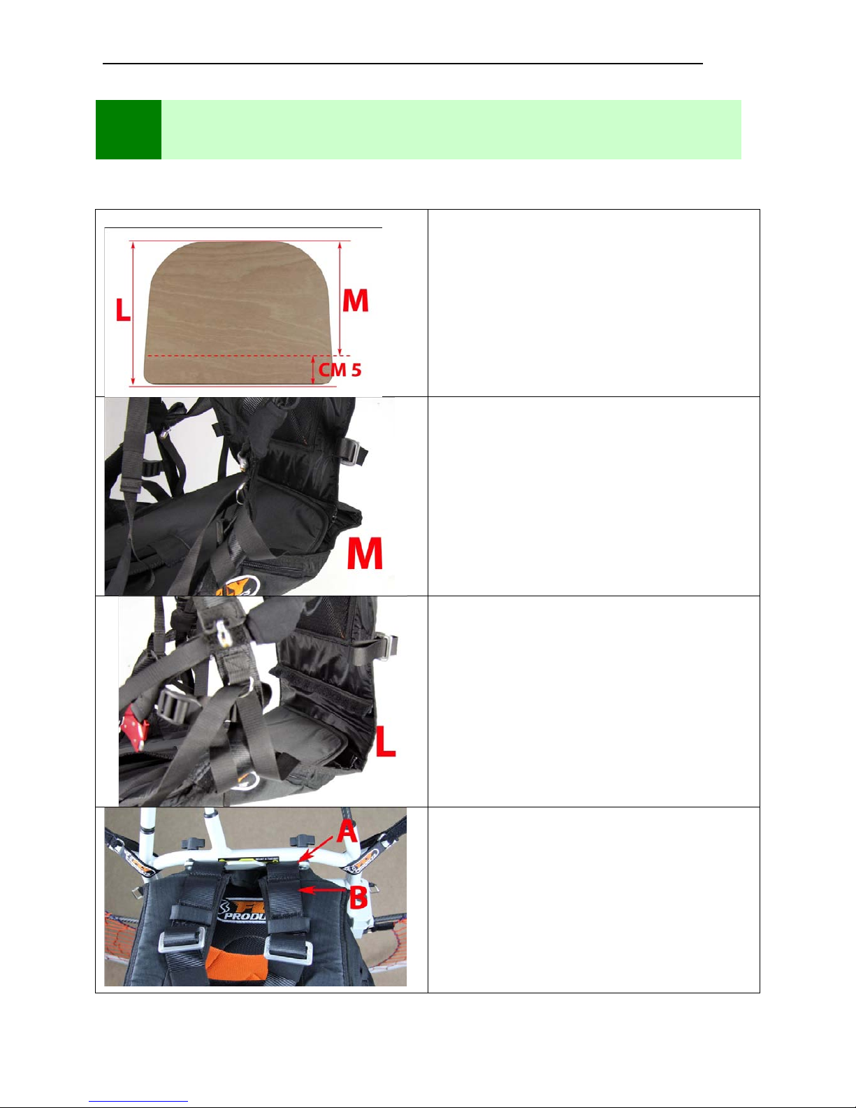
Find the most suited to your needs and verify in the Simulator
Cut along the dotted line to get size M.
Adjusting harness zip size M.
Zip harness adjustment size L.
A Position the harness shallower.
B position the harness deeper
2
HARNESS SIZE ADJUSTMENT
Page 6
ASSEMBLY MANUAL __ REL . 1.1
___________________________________________________________________________
© Copyright by
FLY
PRODUCTS s.r.l. Pag.
6
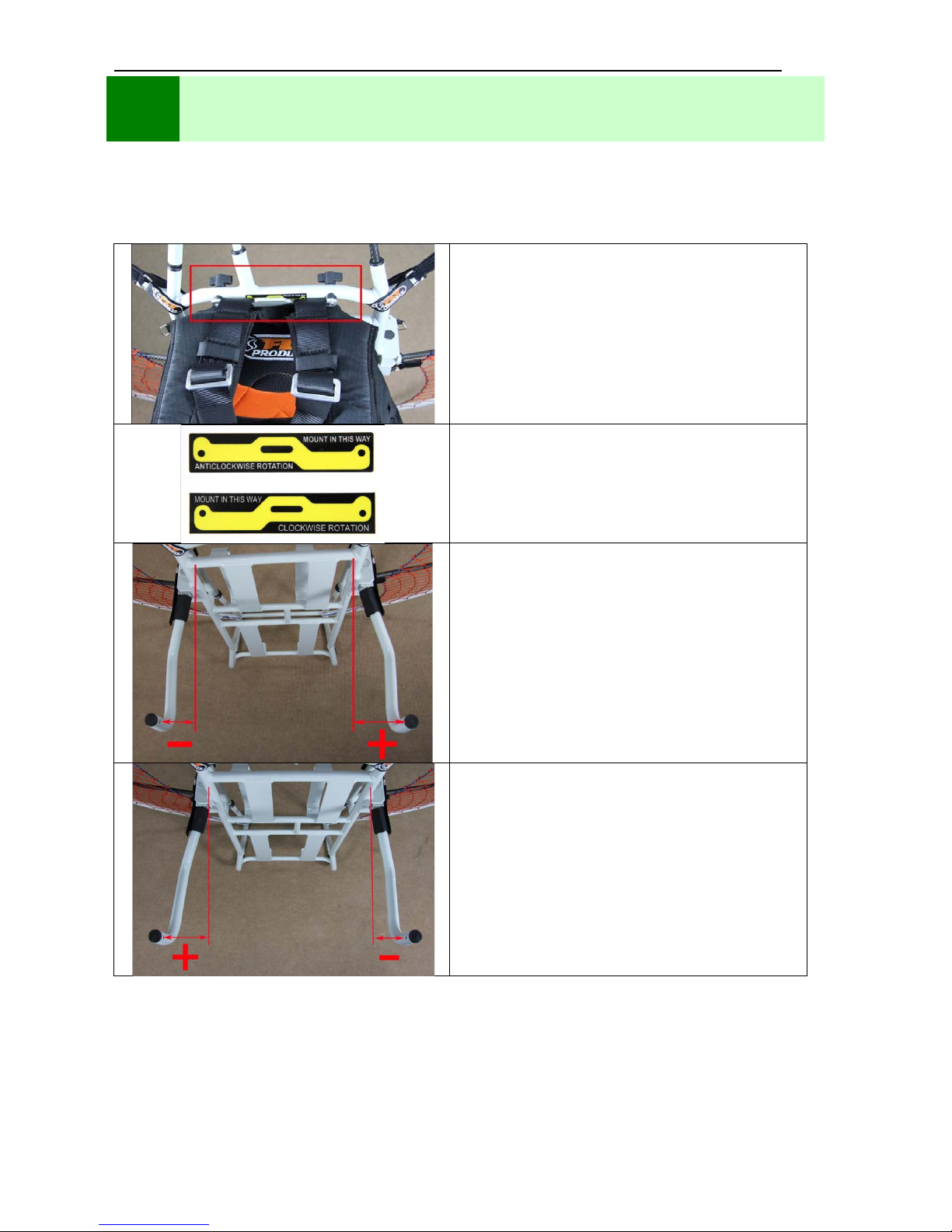
La selletta viene fissata al telaio su tre punti di ancoraggio:
in alto con due bulloni a farfalla, di lato con due distanziali, in basso con due cinghie regolabili.
1) Upper hooks harness with two
Butterfly bolts
Attach the harness to the chassis with the plate
and tighten the two bolts with the butterflies.
ATTENTION
Mount the plate as is indicated on the sticker of
your paramotor
Asymmetric distance bar for:
Rider Thrust.
Anticlockwise rotation of the propeller
Asymmetric distance bar for:
Rider Jet, Rider Race C,
Clockwise rotation of the propeller
3
FITTING THE HARNESS HIGH ATTACK
Page 7
ASSEMBLY MANUAL __ REL . 1.1
___________________________________________________________________________
© Copyright by
FLY
PRODUCTS s.r.l. Pag.
7
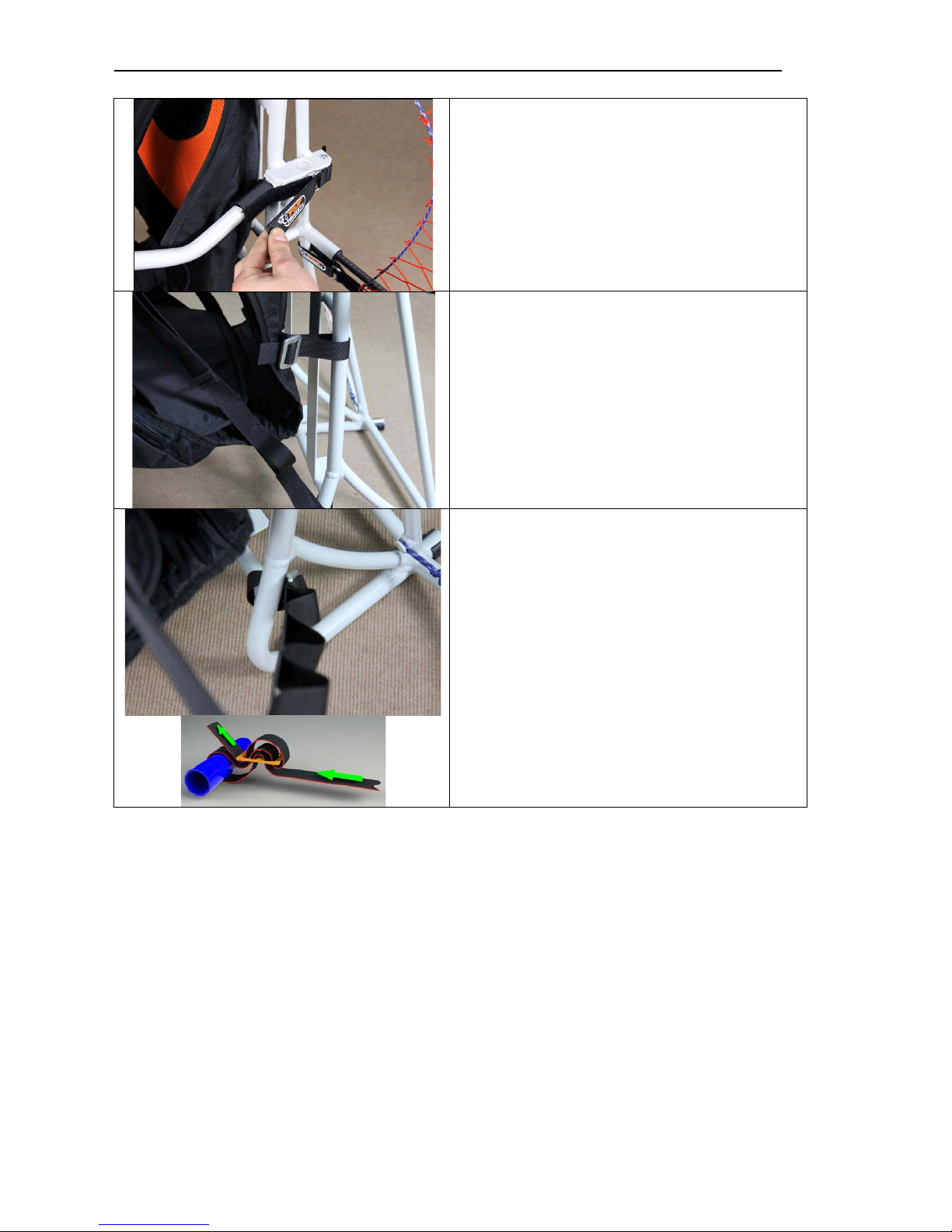
2) Assembly of the distance bars
Insert the distance bar
into the square slot
located on the Central frame and close the
Velcro straps.
3) Lateral belt attachment
Fasten the webbing at maximum length
4) Fastening shou ld er webbing
Attach the webbing to the right and left of the
frame
Page 8
ASSEMBLY MANUAL __ REL . 1.1
___________________________________________________________________________
© Copyright by
FLY
PRODUCTS s.r.l. Pag.
8
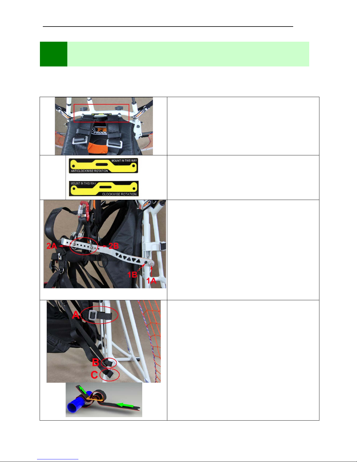
The harness is fastened to the frame on three anchor points: at the top with two Butterfly bolts sideways
with two distance bar and bottom with three belts.
1) Upper hooks harness with two Butterfly
bolts
Attach the harness to the chassis with the plate and
tighten the two bolts with the butterflies.
ATTENTION
Mount the plate as is indicated on the sticker of your
paramotor
2) Fixing the frame distance bars
Mount distance bars accord ing to two
regulations:
Regulation 1:
1A = Pilots over 85 kg.
1B = Pilots less 85 kg.
Regulation 2:
Direction 2A (forward) Heavy Pilots
Direction 2B (back) Light Pilots
3)
Bottom bracket of the frame with three straps
4
ASSEMBLY OF (LOW A CTIVE HANG POINT)
Page 9
ASSEMBLY MANUAL __ REL . 1.1
___________________________________________________________________________
© Copyright by
FLY
PRODUCTS s.r.l. Pag.
9
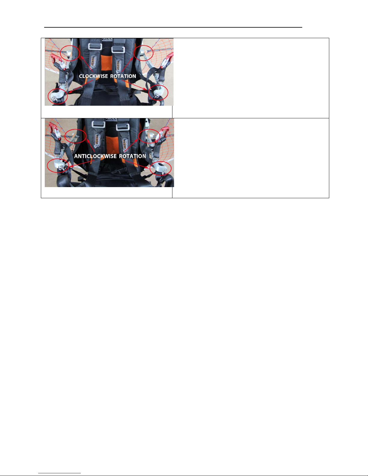
Configuration for:
Rider Sprint, Rider Race C, Rider Jet.
Clockwise rotation of the propeller
Configuration for:
Rider Thrust.
Anti
clockwise rotation of the propeller
Page 10
ASSEMBLY MANUAL __ REL . 1.1
___________________________________________________________________________
© Copyright by
FLY
PRODUCTS s.r.l. Pag.
10
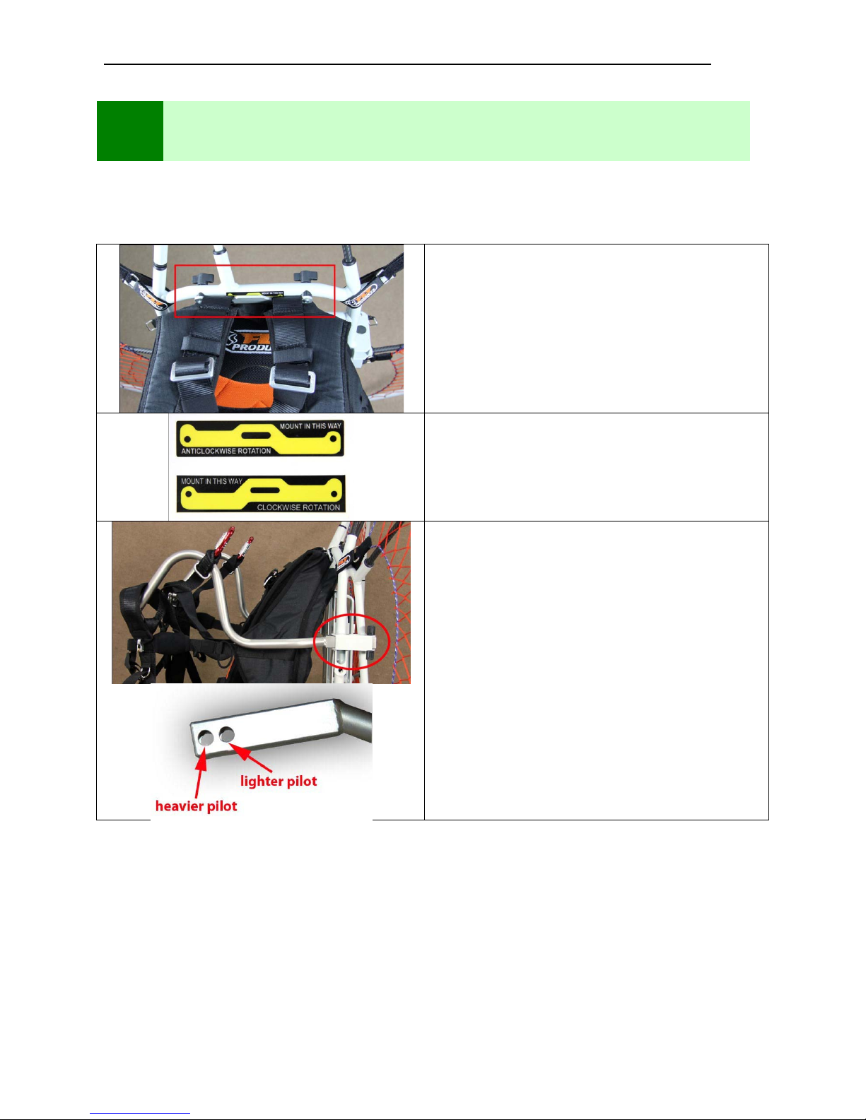
The harness is fastened to the frame on three anchor points: at the top with two Butterfly bolts sideways
with two distance bar and bottom with three belts.
1) Upper hooks harness with two
Butterfly bolts
Attach the harness to the chassis with the plate and
tighten the two bolts with the butterflies.
ATTENTION
Mount the plate as is indicated on the sticker of
your paramotor
2)
Assembly of the spacer bars
Insert the distance bar i nto the square slot located
on the Central frame and secure them with bolts
and butterflies
Assemble the distance bar in one of two holes
according to the pilot weight.
5
ASSEMBLY OF: (FIXED HANG POINT)
Page 11
ASSEMBLY MANUAL __ REL . 1.1
___________________________________________________________________________
© Copyright by
FLY
PRODUCTS s.r.l. Pag.
11
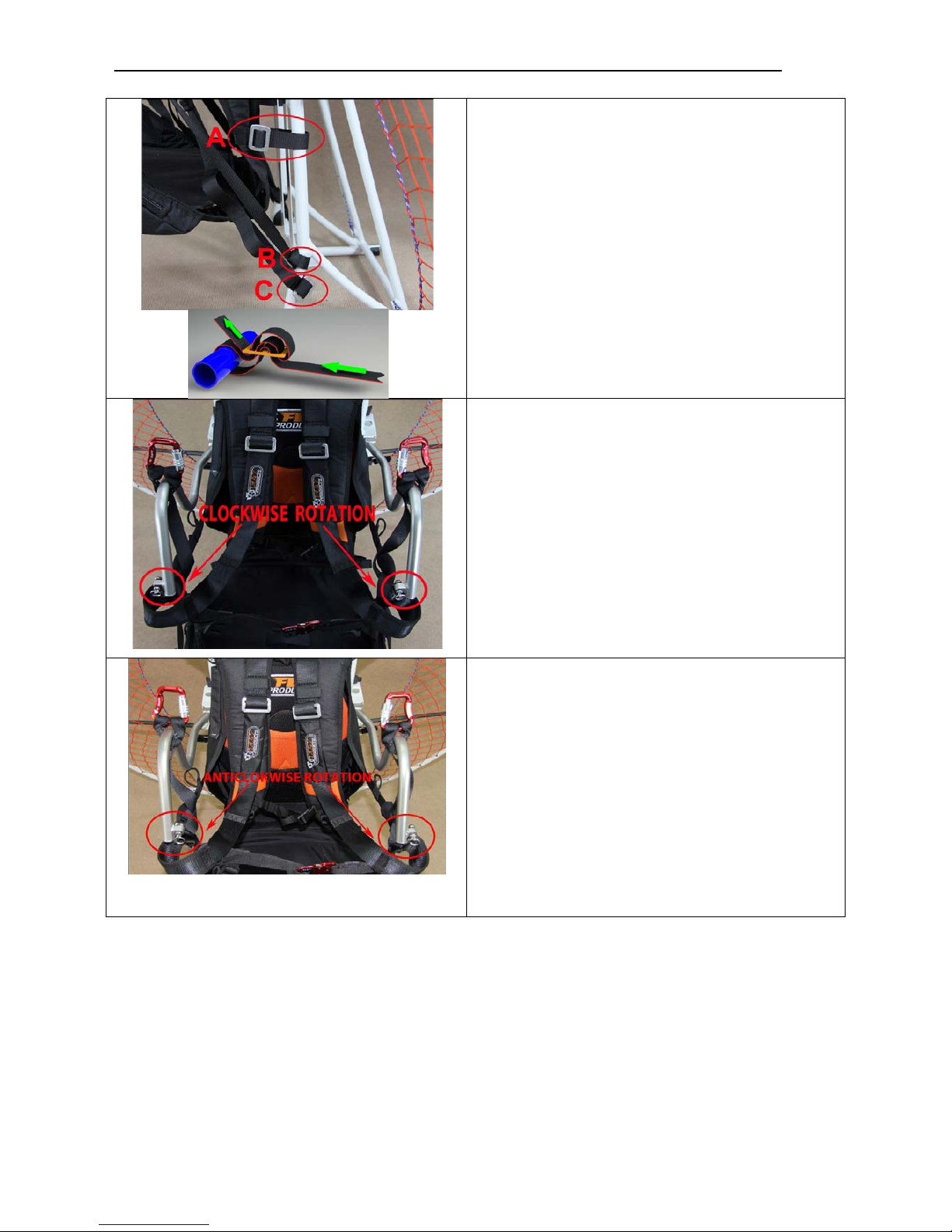
Punto 3:
Bottom bracket of the frame with three
straps
Configuration for:
Rider Sprint, Rider Race C, Rider Jet.
Rotazione oraria dell’eli ca
Configuration for:
Rider Thrust.
Anti
clockwise rotation of the propeller
Page 12
ASSEMBLY MANUAL __ REL . 1.1
___________________________________________________________________________
© Copyright by
FLY
PRODUCTS s.r.l. Pag.
12
6
PROP MOUNTING
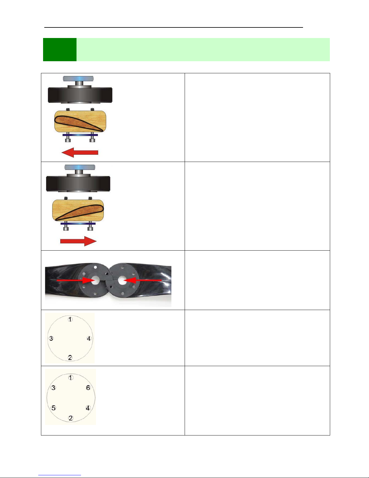
Mount the propeller on the motor with belt
reduction:
Rider Thrust
The red arrow in the illustration indicates the
direction of rotation of the propeller.
Propeller on engine mounting with mechanical
reduction:
Rider Sprint, Rider Race C, Rider Jet.
The red arrow in the illustration indicates the
direction of rotation of the propeller.
Fibreglass propeller mounting
Propeller bolts draft sequence:
Rider Jet
Propeller bolts draft sequence:
Rider Thrust, Rider Sprint,
Rider Race C.
Page 13
ASSEMBLY MANUAL __ REL . 1.1
___________________________________________________________________________
© Copyright by
FLY
PRODUCTS s.r.l. Pag.
13
7
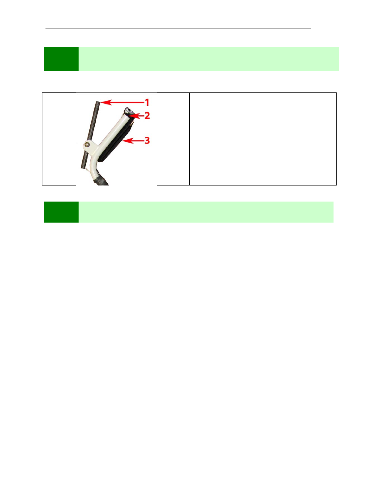
MULTIFUNCTION HANDGRIP
Manual Starter handle
1 – Throttle control lever
2 – STOP" button engine
3 – Velcro hand tightening
8
WARRANTY
WARRANTY
FLY PRODUCTS provides a guarantee on materials and workmanship defects for a period of twelve
(12) months from the date of purchase. The warranty applies only to the normal use of the product.
The dealer from which you purchased the product, or FLY PRODUCTS, will repair the product at no
additional charge.
To obtain warranty service, please contact your local dealer (or directly FLY PRODUCTS), where to
take or ship the product. The shipping expenses are always charged to the buyer.
CAUTION: The warranty, even if valid, shall not apply and all costs necessary to repair will be
totally borne by the buyer in the following cases:
• The cause of the failure is due to an improper use of the product, negligence, neglect, etc. , including
an engine damage due to incorrect or improper fuel regulator oil/gasoline mixture.
• The defect was caused by incorrect pilot operation, for example: accident, fall, or bad regulation.
• The malfunction is due to lacking or insufficient maintenance or changes from the pilot (example: a
loose bolt falls and breaks the propeller ...).
• The damage is caused by natural events or uncontrollable as, lightning, fires, floods, earthquakes etc.
Page 14

ASSEMBLY MANUAL __ REL . 1.1
___________________________________________________________________________
© Copyright by
FLY
PRODUCTS s.r.l. Pag.
14
© Copyright by
FLY
Products s.r.l.
VERSIONE 2.2 – 01.11
Via Perù n. 30
63013 GROTTAMMARE (AP) - ITALY
tel./fax +39.735.632486
www.flyproducts.com - [email protected]
 Loading...