

Page 1

B1
User manual
Document version 1.4
Page 2

B1User Manual
2008 FLYMASTER Avionics Ltd.
Rua de Fundões, 151
3700-121 S. João da Madeira
Portugal
Tel: + 351 256 880 568 / 256 001 935
Fax: + 351 256 880 551
All rights reserved. Except as expressly provided herein, no part of this manual
may be reproduced, copied, transmitted, disseminated, downloaded or stored
in any storage medium, for any purpose without the express prior written
consent of FLYMASTER Avionics Lda. herein FLYMASTER avionics.
FLYMASTER Avionics hereby grants permission to download a copy of this
manual onto a hard drive or other electronic storage medium to be viewed and
to print a copy of this manual or of any revision hereto, provided that such
electronic or printed copy of this manual must contain the complete text of this
copyright notice and provided further that any unauthorized commercial
distribution of this manual or any revision hereto is strictly prohibited.
Information in this document is subject to change without notice. FLYMASTER
Avionics reserves the right to change or improve its products and to make
changes in the content without obligation to notify any person or organization
of such changes or improvements. Visit the FLYMASTER Avionics website
(www.flymaster-avionics.com) for current updates and supplemental
information concerning the use and operation of this and other FLYMASTER
Avionics products.
Version 1.4
Page 3

Warning
It is the sole responsibility of the pilot to operate the aircraft in a safe manner,
maintain full surveillance of all flying conditions at all times, and not become
distracted by the FLYMASTER Avionics is not responsible for any damages
resulting from incorrect or no data provided by the FLYMASTER B1. Flight
safety is the sole responsibility of the pilot.
It is unsafe to operate the FLYMASTER B1 while in the air. Failure by the pilot
equipped with a FLYMASTER B1 to pay full attention to the aircraft and flying
conditions while flying could result in accident with property damage and/or
personal injury.
3 Version 1.4
Page 4

B1 User Manual
Table of contents
1. Introduction ......................................................................................................... 5
2. Getting started ..................................................................................................... 5
2.1. The Keys ................................................................................................................... 6
2.2. Turning the Unit On and Off ...................................................................................... 7
3. Understanding the Flight Screen ........................................................................... 8
3.1. Altitude graph ........................................................................................................... 8
3.2. Flight Duration .......................................................................................................... 9
3.3. Altimeters 1, 2 and 3 ................................................................................................. 9
3.4. Sound Level ............................................................................................................... 9
3.5. Time ......................................................................................................................... 9
3.6. Digital and analogue variometer ................................................................................ 9
3.7. Maximum and Minimum vertical speed ................................................................... 10
4. Resetting Altimeter 3 .......................................................................................... 10
5. Settings .............................................................................................................. 10
5.1. Flight Log ................................................................................................................ 11
5.2. Set Altimeter ........................................................................................................... 12
5.3. Digital Vario ............................................................................................................ 13
5.4. Date Time ............................................................................................................... 14
5.5. Acoustic Thresholds ................................................................................................. 15
5.6. Audio Frequencies ................................................................................................... 16
5.7. Advanced Features .................................................................................................. 17
5.7.1. Damper ..................................................................................................................................... 18
5.7.2. Cadence .................................................................................................................................... 18
5.7.3. Dynamic Frequency .................................................................................................................. 18
5.7.4. Buzzer (Next to Climb Indicator) .............................................................................................. 18
5.7.5. Auto Silent ................................................................................................................................ 19
5.8. Screen Contrast ....................................................................................................... 20
5.9. Language/Units ....................................................................................................... 20
5.10. Firmware ............................................................................................................... 21
5.11. Shutdown .............................................................................................................. 21
6. Updating B1 Firmware ........................................................................................ 22
7. .Fail Safe firmware update .................................................................................. 24
7.1. Introduction ............................................................................................................ 24
7.2. Update procedure ................................................................................................... 24
Version 1.4 4
Page 5
1. Introduction
Thank you for choosing FLYMASTER B1. This version of the user manual was
made for the 1.35 version of the Firmware.
If you have any questions or comments regarding the use of your vario you can
visit our website at http://www.flymaster-avionics.com or contact our Support
Department ([email protected])
2. Getting started
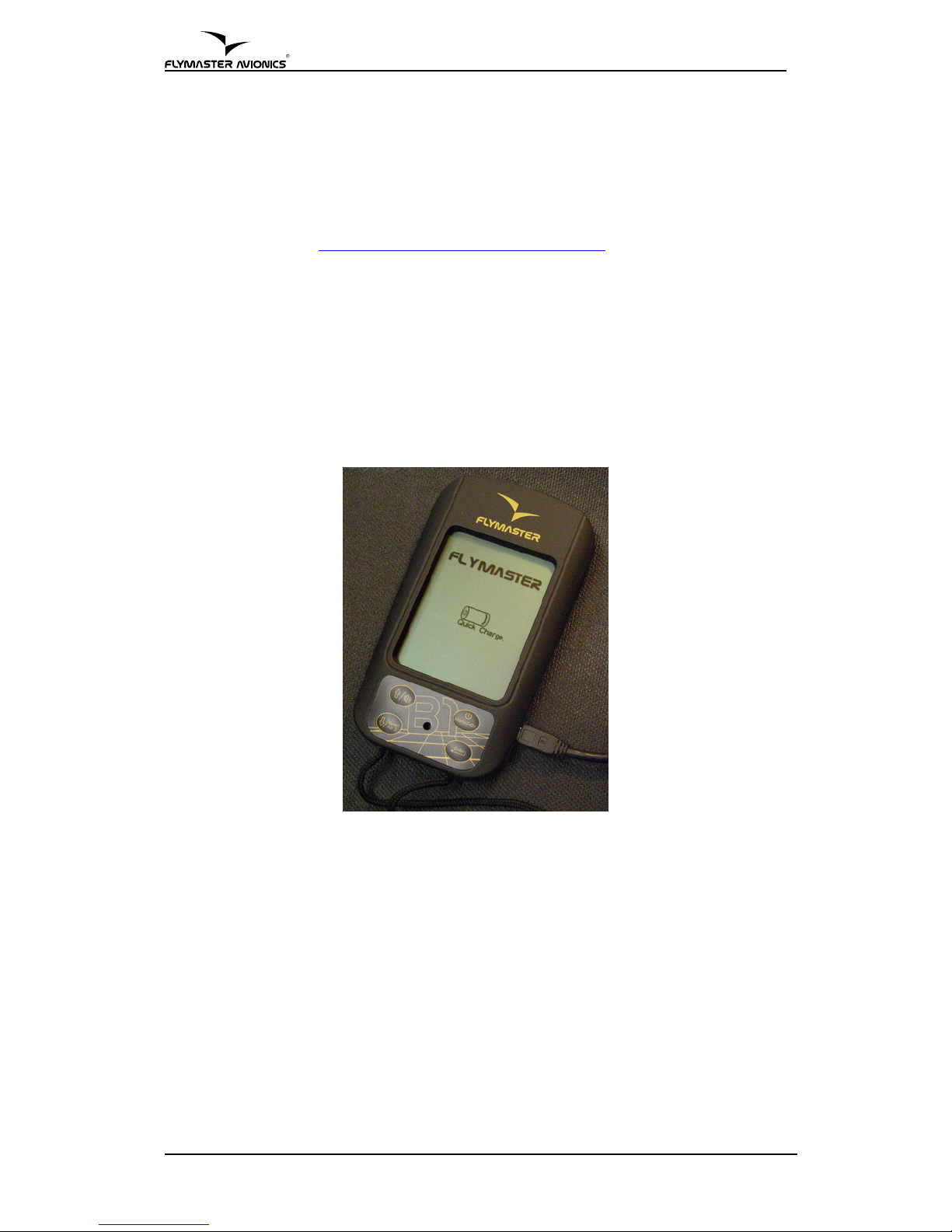
Fully charge the battery before start using FLYMASTER B1.
Charging battery can be performed either by connecting the wall socket charger
or the PC USB cable (both included in the package) to the B1 USB port located
on the right side of the B1 (see Figure 1).
Figure 1 –Battery charge connection
The charging process is automatically stopped once the battery is fully charged.
A message appears on the screen indicating the charging level and the end of
the process. Note that the charger is capable of fully charging the battery in
approximately 3 hours (quick charge), whilst the USB connecting may take up
to 5 hours (slow charge).
B1 uses a Lithium-ion polymer battery, which is not prone to “memory effect”,
so the battery does not need to be totally discharged before recharging. Full
charge lasts for over 20 operating hours, but recharging before each flight is
strongly recommended.
5 Version 1.4
Page 6
Page 7
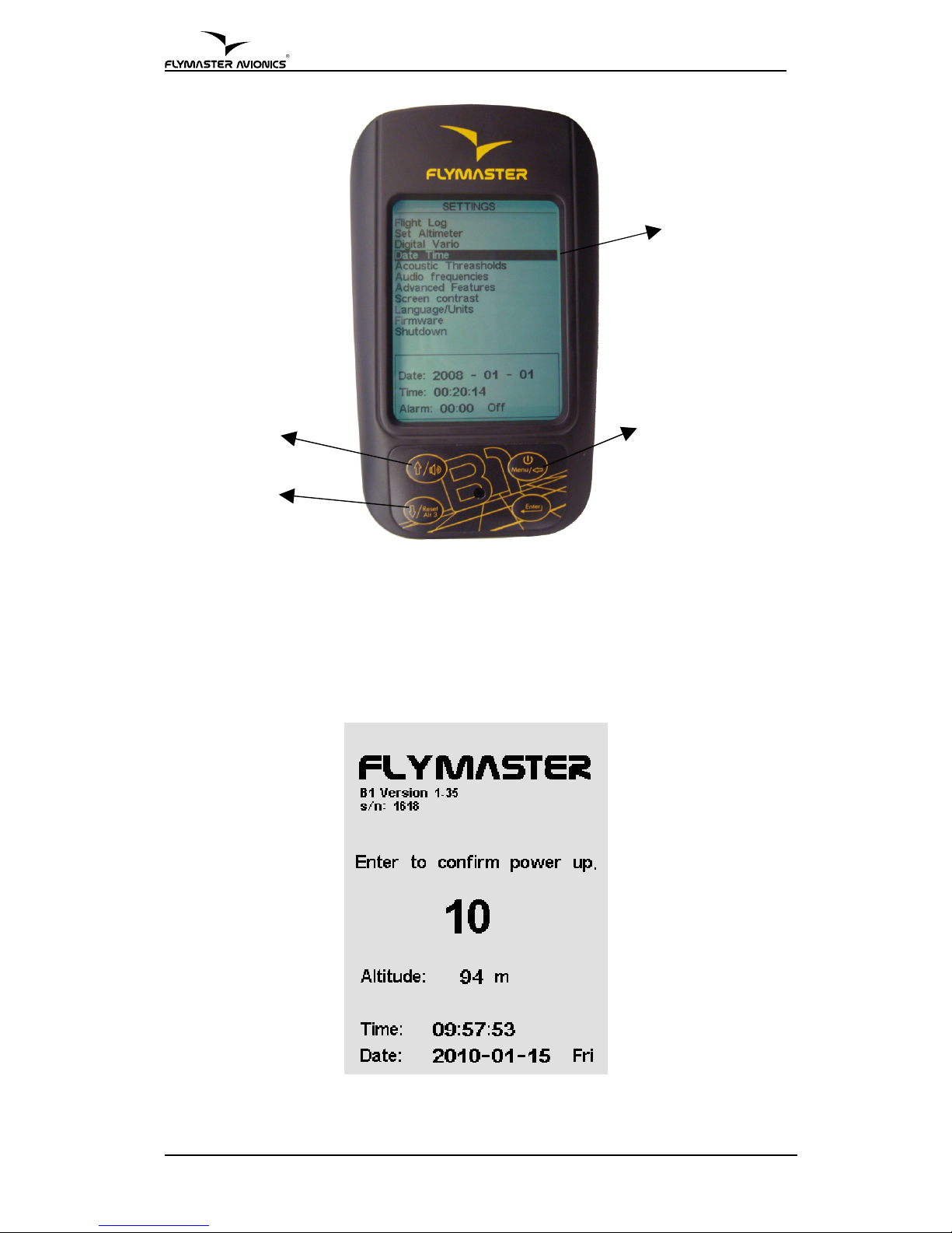
Figure 3 –Settings Menu Mode
2.2. Turning the Unit On and Off
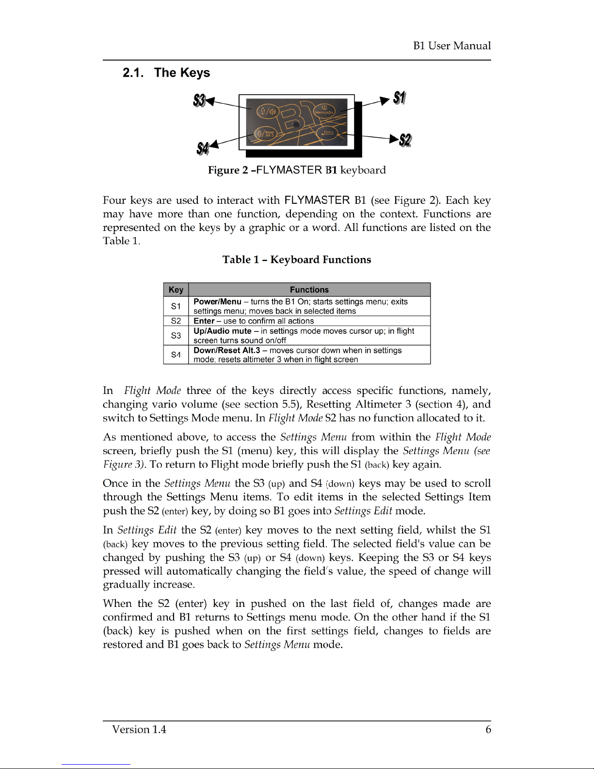
To turn on the B1, briefly push the S1 key, this will display the start up screen.
A 10 second countdown will start, push the S2 (Enter key) to confirm power up
before time is elapsed
Figure 4 –Start up Screen
7 Version 1.4
Move UP
Move Down
Selected Option
Settings Menu
Access
Page 8
B1 User Manual
Turning off the B1 is made by selecting “Shutdown” on the settings menu
mode. This is done by briefly pressing the S1 key, then using the S3 (up) or S4
(down) keys to select “Shutdown” option, and then pressing S2 (Enter key).
The flight timer will start automatically whenever the altitude varies more than
5 meters. The timer stops when the B1 is turned off. When a flight is started,
data collected during flight time is automatically recorded in the internal
memory. This information can be later seen on the B1 screen, or can be
downloaded to the PC for analysis and storage in the B1 FLYMASTER Suite's
database.
3. Understanding the Flight Screen
The FLYMASTER B1 has a high resolution (320x240) and contrast display. This
allows it to show more useful information simultaneously. The flight screen can
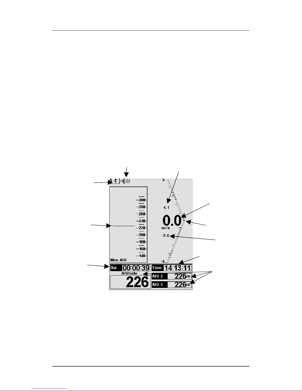
be seen in Figure 5 each field has a self explanatory text tag.
Figure 5 – Flight Screen
3.1. Altitude graph
The FLYMASTER B1 has an altitude graph. Whenever the flight starts a line is
draw representing the altitude in meters (or feet) versus time, in seconds.
Altitude is represented in the vertical axis, and time in the horizontal axis.
Version 1.4 8
Analogue Vario
Digital Vario
Time
Altimeter
Flight
Duration
Real-time
altitude graph
Max. Climb
Max. Sink
Sound Level
Battery
Page 9
Page 10

B1 User Manual
50ft/min, depending on the settings chosen (see section 5.9). Values between ±
10 m/s(±100ft/min) are also indicated as when the vertical speed increases, or
decreases, the bar is filled proportionally until the full scale value (±5 m/s) is
reached, and then, for higher values (ex. ±6, ±7...), the bar is cleared from the
bottom up until being completely empty at ±10 m/s.
Adjacent to the analogue variometer there are two digits that correspond to the
digital variometer. The resolution of the digital vario is 0.10 m/s, or 10ft/min,
and the full scale is reached at ±99 m/s, or 990ft/min(see section 5.9) .
The digital variometer differs from the analogue variometer, in that the values
are averaged to a set time base of the. This time base is factory defaulted to 10
seconds, but may be defined by the user (see section 5.3). For this reason the
digital variometer is called the integrated variometer. The integrated
variometer is particularly useful in determining the actual strength of a bumpy
thermal.
3.7. Maximum and Minimum vertical speed
Above and below the digital variometer there are two smaller figures. These are
constantly updated and represent the maximum positive and negative vertical
speeds since the flight has started. The saved values correspond to the
integrated vario, so they depend on the integration time defined by the user.
The figure above the digital vario value corresponds to the maximum rate of
climb, and the figure below the digital vario to the maximum rate of sink. These
values are automatically reset once when the B1 is turned off.
4. Resetting Altimeter 3
When in flight mode, Altimeter 3 can be rapidly set to 0 by briefly pushing S4
key. This is useful for creating a reference altitude marker during a flight. For
instance, if you reset the Altimeter 3 upon entering a thermal, you can easily
monitor the total altitude gain in that thermal.
5. Settings
Almost all the FLYMASTER B1 parameters can be adjusted using the settings
menu. By changing parameter values the user can easily adapt features as the
variometer acoustics, time, or display contrast, just to name a few. The menu
can be accessed by pressing the S1 key for more than 1 second.
Version 1.4 10
Page 11
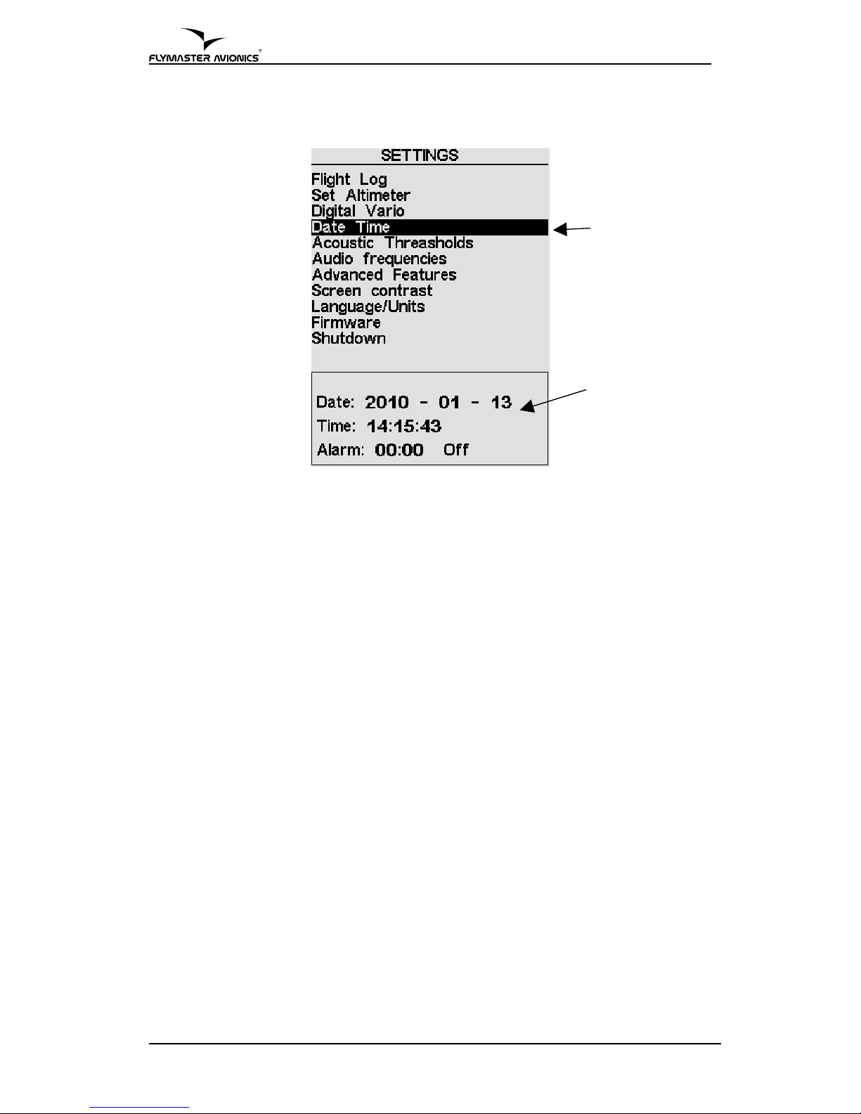
Figure 6 –Settings Menu Options
The settings menu screen is divided in two parts (see Figure 6). The top one
shows all the settings menu options.
Menu option can be changed by pressing S3 and S4 keys. The current menu
option is always highlighted and for most of the options his parameters can be
seen on the bottom part of the screen.
A highlighted option can be accessed by pressing S4 key (Enter key).
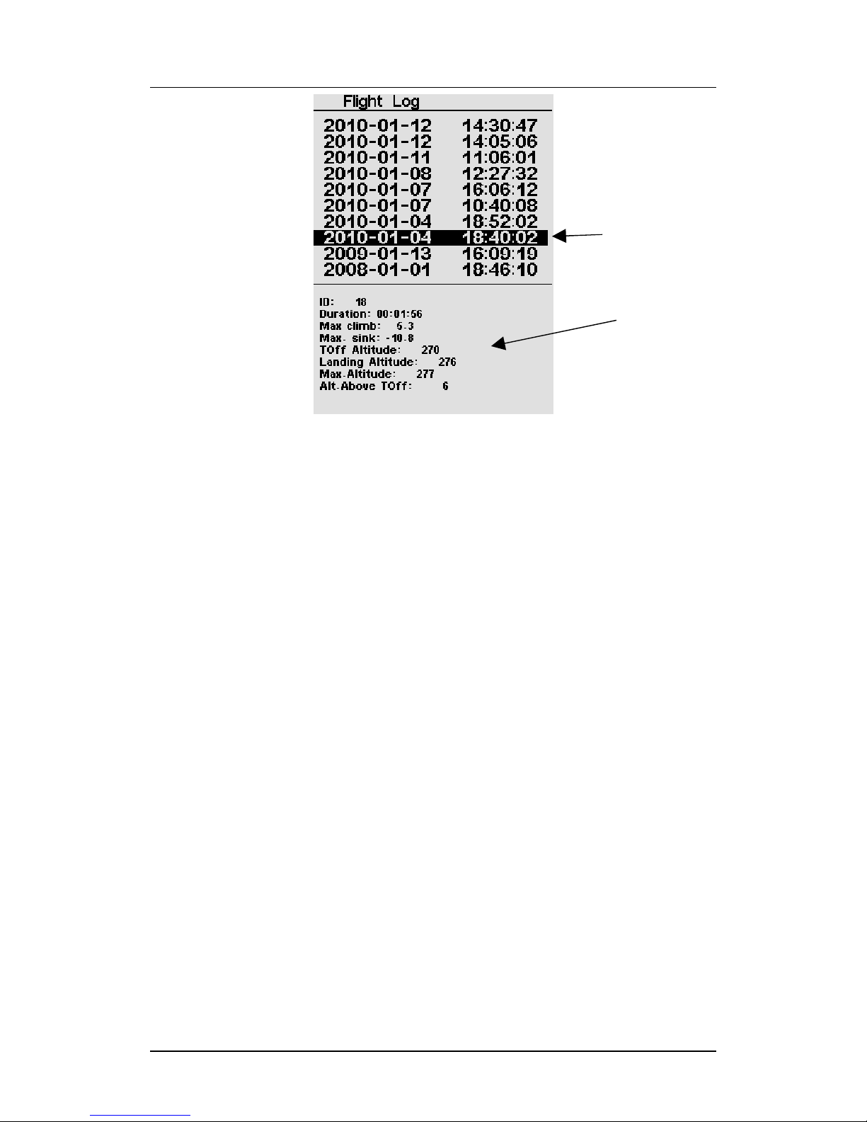
5.1. Flight Log
The Flight Log option allows the user to access information about previews
saved flights. In the top of the screen a list of flights is showed (see Figure 7).
Each flight is identified by the take off date and time.
11 Version 1.4
Option Selection
Parameters
Page 12
B1 User Manual
Figure 7 –Flight Log
Flights can be chose by using S3 and S4 keys. For each flight the flowing
information is displayed:
• ID – Flight identification
• Duration – Flight duration
• Max Climb – Maximal climbing rate
• Max Sink – Maximal sinking rate
• TOff – Take Off altitude (altimeter 1)
• Landing Altit – Landing altitude (altimeter 1)
• Max. Altitude – Maximum altitude during flight (ASL).
• Alt. Above Take Off – Maximum altitude above Take Off.
5.2. Set Altimeter
The ”Set Altimeter” option allows the user to change the current value of the
QNH, change the 3 altitude values for each of the available altimeters and
define the number of altimeters that are shown in the Flight Screen (see Figure
5).
Pressing S2 to enter the Set Altimeter option, the edition of QNH automatic
starts, you can define the value using S3 and S4, to pass to the next number just
press S2.
After the edition of the QNH the first altimeter will become highlighted, and
the value can be changed using S3 and S4 keys, when the desirable value is
Version 1.4 12
Selected Flight
Flight Data
Page 13
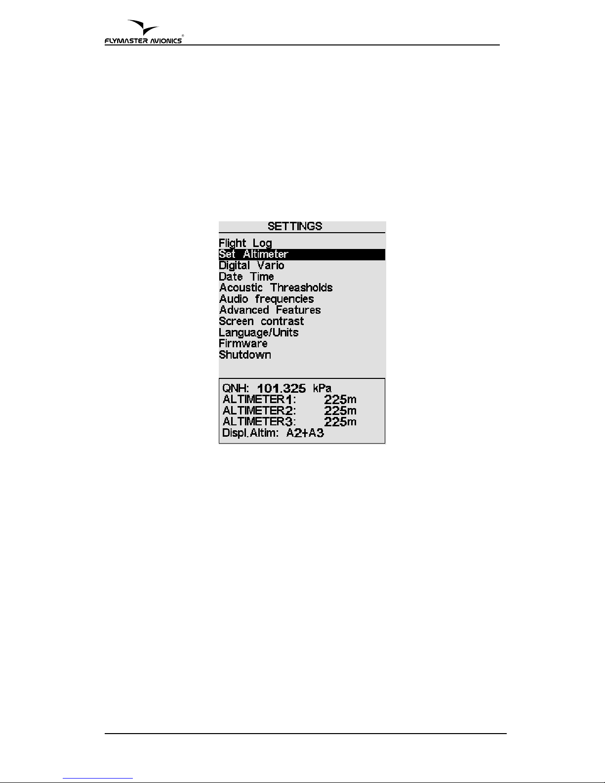
introduced press S2 to pass to the next altimeter press S2, to return to the
previous press S1.
Note: The Altimeters 2 and 3 are directly linked to Altimeter 1, changing altimeter 1 will
automatically change the other 2 in the same proportion.
The final option allows defining the number of visible altimeters in the Flight
Screen in addition to Altimeter 1, you can choose from seeing Altimeter 3, or
seeing Altimeter 2 and 3. When viewing only 2 altimeters will display Altimeter
3 in large characters. Define the desired option using the S3 and S4, and to
confirm and return to the settings menu press S2.
Figure 8 –Set altimeter
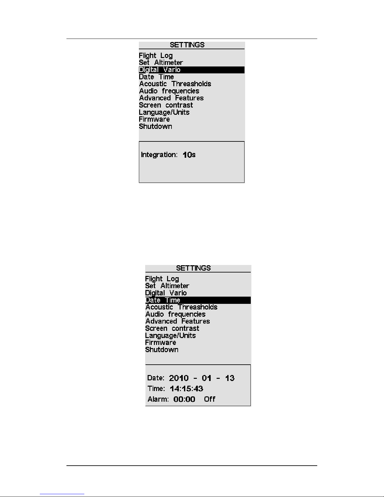
5.3. Digital Vario
Setting the integration time for the digital vario discussed in section 3.6 may be
done using this menu item.
After pressing S2 (Enter) key, the integration time period can be changed using
S3 and S4 keys.
The default Digital Vario integration value is set 10 seconds.
13 Version 1.4
Page 14
B1 User Manual
Figure 9 –Digital Vario
5.4. Date Time
The Date Time menu option allows the user to set the internal B1 time and date.
This value is used to identify each flight log. This option allows also to set an
alarm. The alarm can be useful to wake up in the morning dreaming of a good
thermal. .
Figure 10 – Date Time
In order to set the time and date the user should press the S2 key. Each time the
S2 key is pressed a value is highlighted in the following sequence: year, month,
Version 1.4 14
Page 15

day, hour, minute, second. The highlighted value changes if S3 and S4 keys are
pressed.
The alarm can be set in the same manner, namely pressing the S2 key to
highlight the hour, minute or On/Off, and then the S3/S4 key to change the
value.
Regarding the alarm, when the hour previously specified is reached a beep...
beep... sound will be eared as we were in a strong thermal. The backlight will
also flash. The alarm can be stopped or snoozed by pressing S1 and S2 key
respectively.
5.5. Acoustic Thresholds
The user can change the climbing and sinking rate sound trough the respective
threshold values. These thresholds correspond to the climbing and sinking rates
at which sound activates.
The user can also define in the Acoustic Thresholds option the sink alarm and
the sound volume of is B1.
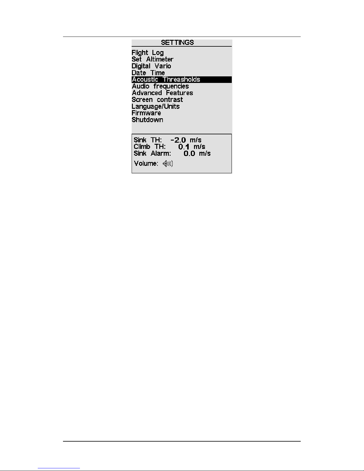
The sinking threshold is set to -2 m/s by default. The value can be changed by
pressing the S2 key when the “Acoustic Thresholds” option is highlighted on
the settings menu. This action will highlight the “Sink TH” threshold which can
be changed using S3 and S4 keys to increase and decrease the value.
Confirmation should be made by pressing S2 key, which at the same time
highlights the “Climb TH” threshold, and same procedure can then be used to
adjust the sinking threshold. The “Sink Alarm” is highlighted when the
confirmation of “Climb TH” is made.
The sink alarm option allows the activation of a siren type alarm, to alert that a
predefined sink velocity as been reached, adjust the sink alarm using the
previously described procedures, and press S2 to confirm and to move to the
next option.
The final option allows the user to adjust the sound volume.
When the sound symbol is highlighted, the B1 beeps 5 times to demonstrate the
currently selected sound level. Using the S3 and S4 keys the sound level can be
adjusted to the desired volume. The B1 has 3 volume levels approximately
corresponding to the values of the following table.
Table 2 – Sound Volume Levels
Level 3 High
Level 2 2/3
Level 1 1/3
Further more the sound may be muted/un-muted in the flight screen, pushing
the S3 key for more than 2 seconds will cause the volume level to be muted and
an arpeggio sound is played.
15 Version 1.4
Page 16
B1 User Manual
Figure 11 – Acoustic Thresholds
5.6. Audio Frequencies
The “Audio Frequencies” settings menu option allows the user to adjust the
vario tone to his preference, by adjusting the “Base Frq” and “Increments”.
The “Base Frq” is the first frequency used to produce the initial sound which
corresponds to the climb threshold, usually 0.1 m/s. Later, as the climb rate
increases, a bip, bip sound is produced for which the cadence and frequency
also increase. The “Base Frq” can be set between from 500 to 1500 Hz. The
higher is the frequency value, the more strident is the sound.
The “Increments” parameter sets the frequency increment for each 0.1 m/s
climb rate increase. The “increments” can be set from 1 to 99 Hz.
The preset values for “Base Frq” and “Increments” are respectively 700 Hz and
10 Hz.
In order to change the base frequency value press S2 key after “Audio
Frequencies” menu option is highlighted. This action will highlight the “Base
Frq” value so it can be increased using S3 key or decreased using S4 key. S2 key
should then be pressed, thus confirming the “Base Frq” setting and highlighting
the “Increments” option.
The same procedure can be used to change the “Increments”, after you chose
the value for the increments, to confirm and return to Settings menu press S2.
Version 1.4 16
Page 17
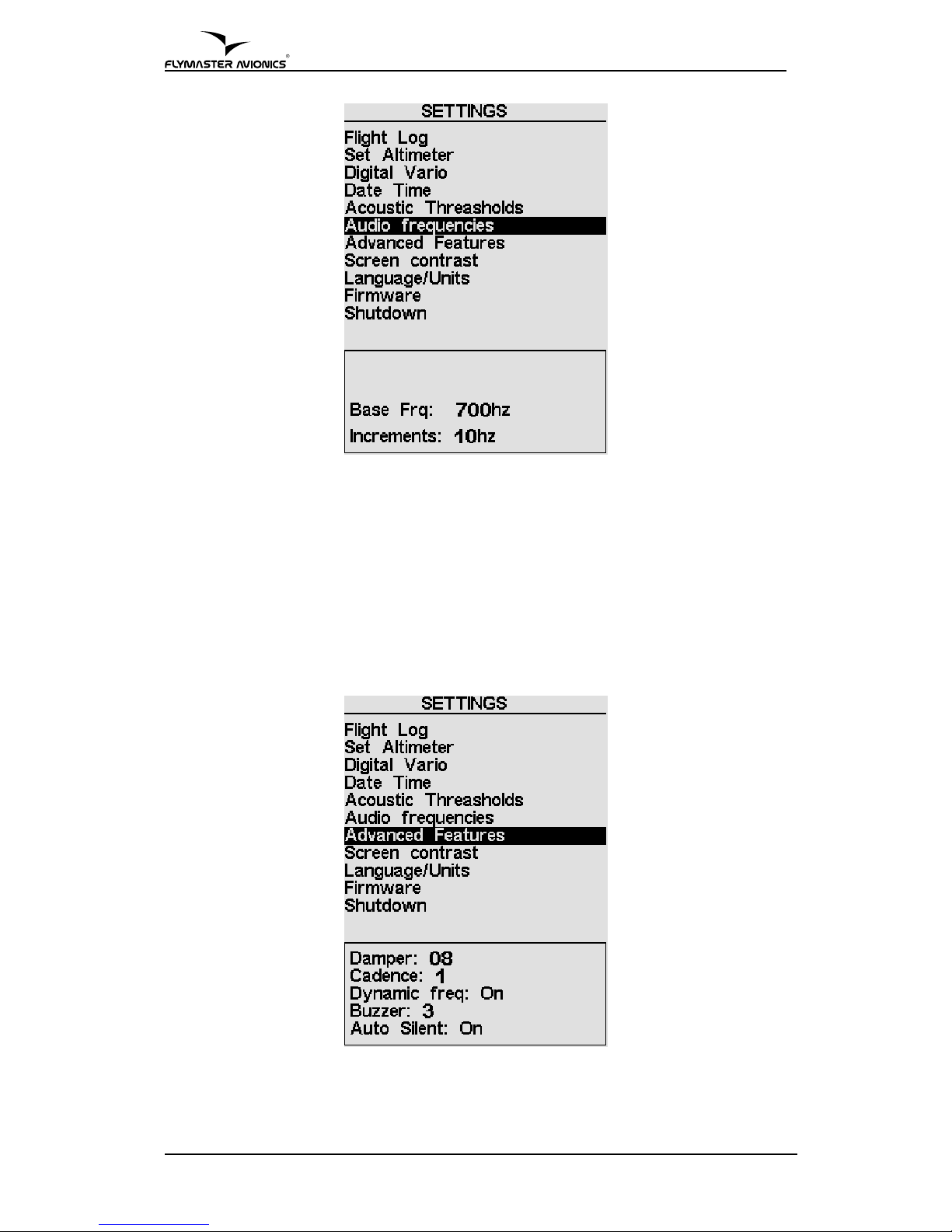
Figure 12 – Audio Frequencies
5.7. Advanced Features
The advanced features settings option can be used to adjust the B1 acoustics to
the user preferences. Using these features the user can turn the vario sound
more or less responsive, and can also turn on and off the buzzer functionality.
There are following four advanced features:
Figure 13 – Advanced Features
17 Version 1.4
Page 18

B1 User Manual
5.7.1.Damper
The damper determines the relation between climb acceleration and sound
frequency increase. Higher values turn the B1 more stable and thus having a
slower response to increased climb rates. Lower values make the B1 be less
stable and respond faster.
B1 Damper default value is 8.
5.7.2.Cadence
Cadence can be set to 0 or 1. When set to 0 will cause the beeping cadence to
beep slower initially and speed up faster later, wile when set to 1 will cause B1
to beep faster at the beginning but evolve slower. The Cadence default value of
the B1 is 1.
5.7.3.Dynamic Frequency
Dynamic Frequency can be set to “On” or “Off”. When on the sound frequency
may change during a beep, otherwise the frequency will be steady. Default
value for dynamic frequency is on.
5.7.4.Buzzer (Next to Climb Indicator)
B1 features a next to climb acoustic indicator, which is an important
FLYMASTER development in detecting weak lifts. This indication can be set to
be always On, or to start only when an altitude variation of ±5 meters is
detected (see section 5.7.5).
A usual vario starts beeping when the pilot experiences a certain climb speed,
for example 0.1 m/s, and this will not happen until the air is rising at a higher
rate than the glider sink rate. In these conditions, typically the air must be rising
at more than 1 m/s before the usual vario makes the first beep.
The B1 can be set to release acoustic information well before that, when just
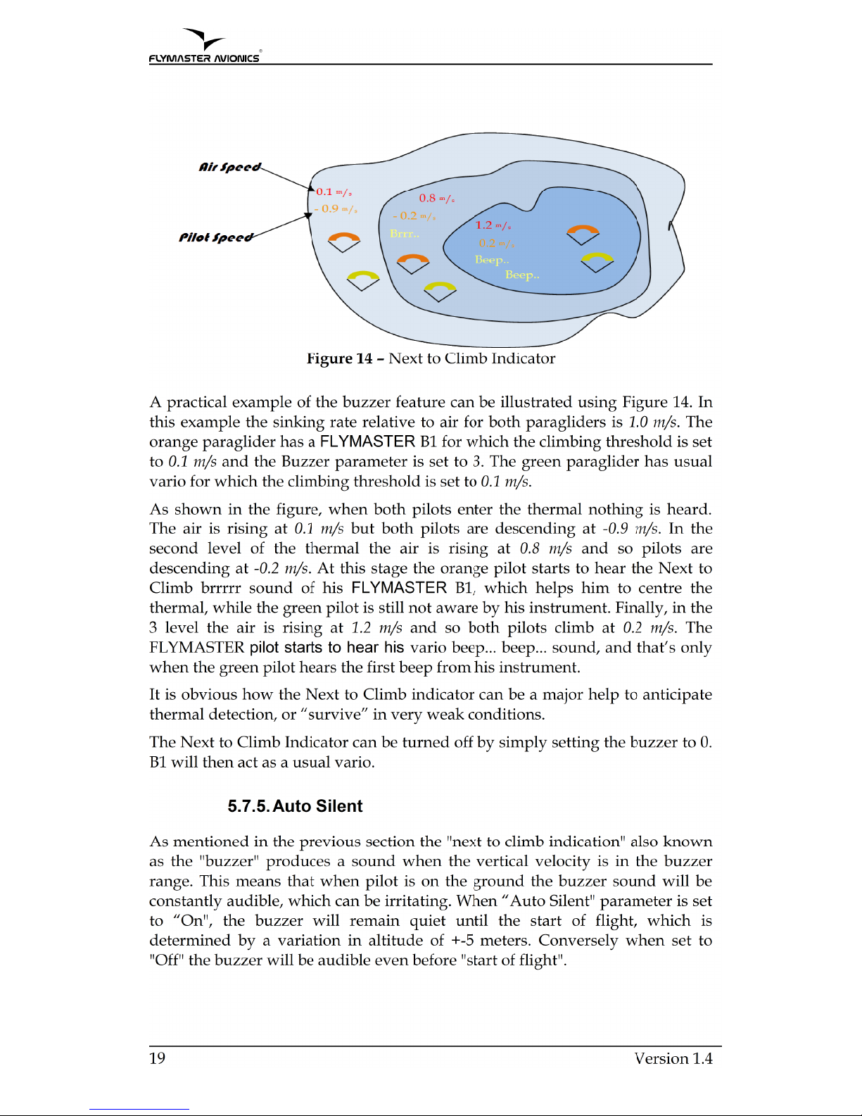
about next to climbing. The “Next to Climb Indicator” helps the pilot to detect
rising air starting from 0 m/s. The “Buzzer” parameter is used to calculate the
value at which the vario starts to “buzz”. This value is subtracted from the
Climb Threshold. Consider the following example were the Climb Threshold is
0.1 m/s and Buzzer is 3.
Climb Threshold = 0.1 Buzzer = 3
0.1–0.3 = -0.2 m/s
In this case B1 will start to buzz when the pilot’s vertical velocity is greater than
-0.2 m/s, i.e. at -0.19999 m/s and over. Naturally, the B1 will make the usual
beep... beep... after the climbing threshold is reached, which in this example is
0,1 m/s.
Version 1.4 18
Page 19
Page 20
B1 User Manual
5.8. Screen Contrast
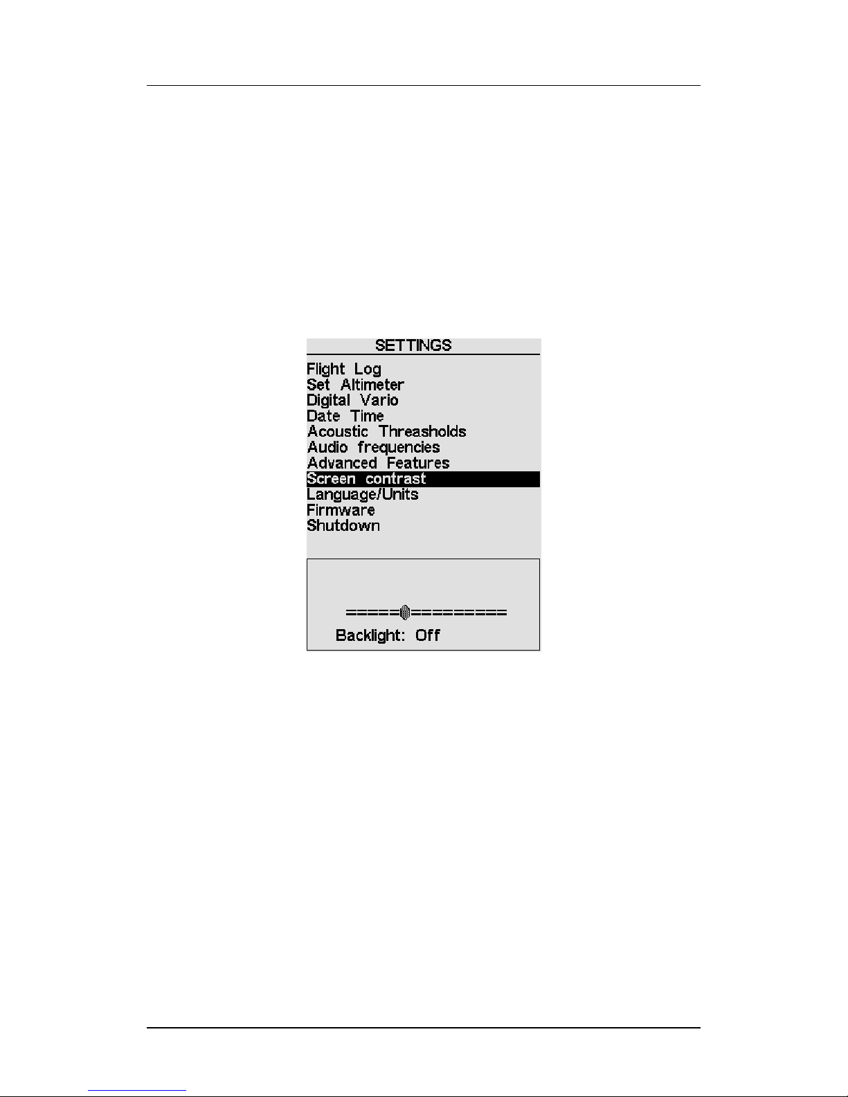
The screen contrast menu allows changing of the display contrast. The contrast
level is shown trough a sliding bar. The bar can be moved to the right using the
S3 Key. This action will turn the screen darker. Inversely, the bar can be moved
to the left using S4 key which will turn the screen to be lighter. After selection,
the new setting must be confirmed using S2 key to pass to the next option.
The Backlight option allows the user to activate the backlight of the screen,
choose the desirable option with the S3 and S4 buttons, to confirm and return to
the settings menu press S2.
Note: The activation of the backlight reduces the duration of the battery. His use in low
battery conditions is not advised.
Figure 15 – Screen Contrast
5.9. Language/Units
The “Language/units” menu option allows the user to change the B1 interface
language and the measure units of the altimeter and the vario.
In order to do that the user should press S2 (Enter) key, and then use S3 and S4
keys to chose the desired language. In the end the choice should be confirmed
pressing S2 key.
After the S2 key is pressed the Alti. Units parameter is highlighted, in this you
can define the units system of the B1 altimeters.
You can choose from SI to English System using S3 and S4 keys. The choice
should be confirmed pressing the S2 Key, and passing to the next option.
Version 1.4 20
Page 21
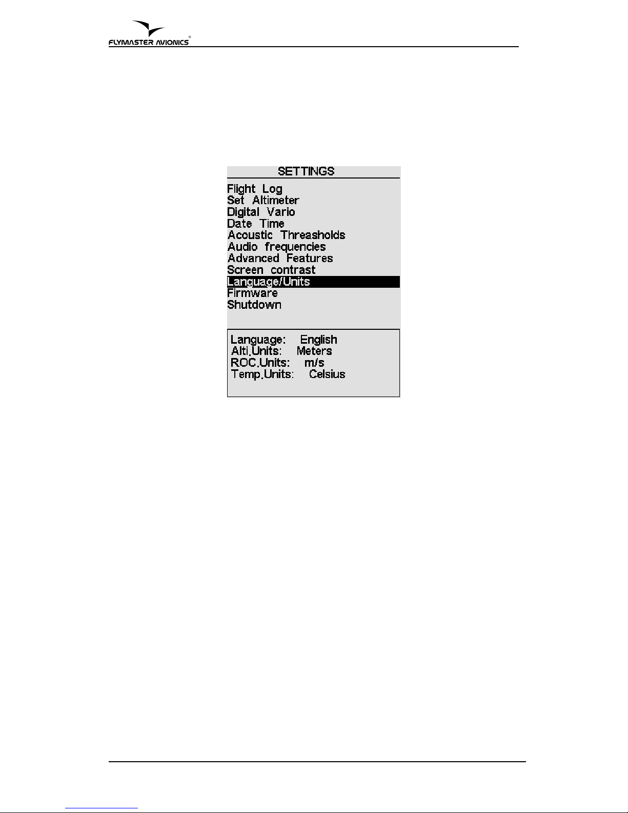
The ROC. Units(Rate of Climb Units) parameter allows the user to define the
units of the varios shown in the Flight screen, you can chose from meters per
second (m/s) or feet per minute (ft/min).In this last option the represented
value correspond to 10 times greater value, meaning that for a value of 5 ft/min
shown the is reality means that the value is 50 ft/min.
Figure 16 – Language/Units
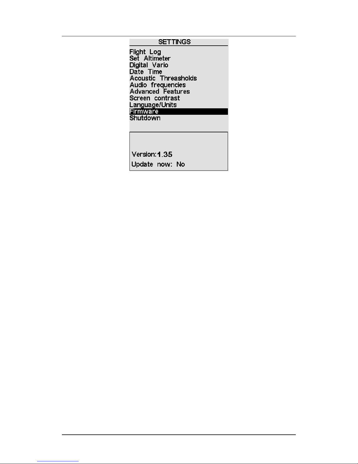
5.10. Firmware
This option allows that B1 firmware been updated very easily. In order to
update your B1 please see section 6.
5.11. Shutdown
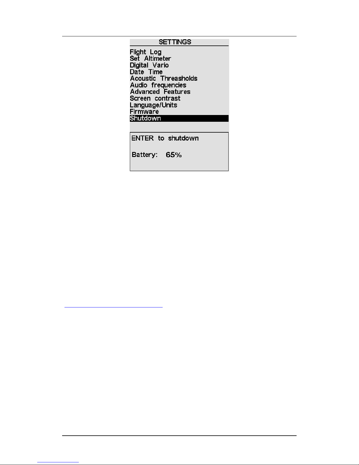
When Shutdown menu option is highlighted the user can see the level of the
battery in percentage, if S2 key is pressed, the B1 is turned off.
The B1 has automatically saved all flight data before it had been turned off.
21 Version 1.4
Page 22
B1 User Manual
Figure 17 – Shutdown
6. Updating B1 Firmware
The B1 firmware update can be done using 3 distinct methods:
• Automatic- by using the FLYMASTER B1 Suite(available on
FLYMASTER site)
• Manual- explained in the current section
• Fail Safe- in case of an unexpected error occurs, explained in section 7.
The manual update of the firmware is a simple procedure that adds new
features to the B1 firmware.
Before beginning update procedure make sure you download from our site
(www.FLYMASTER-avionics.com)the next list of files:
• USB Drivers (FlymasterUSBdrivers.msi)
• The last version of the firmware(B1Firmware.b1b)
• The update application(FlashB1.exe)
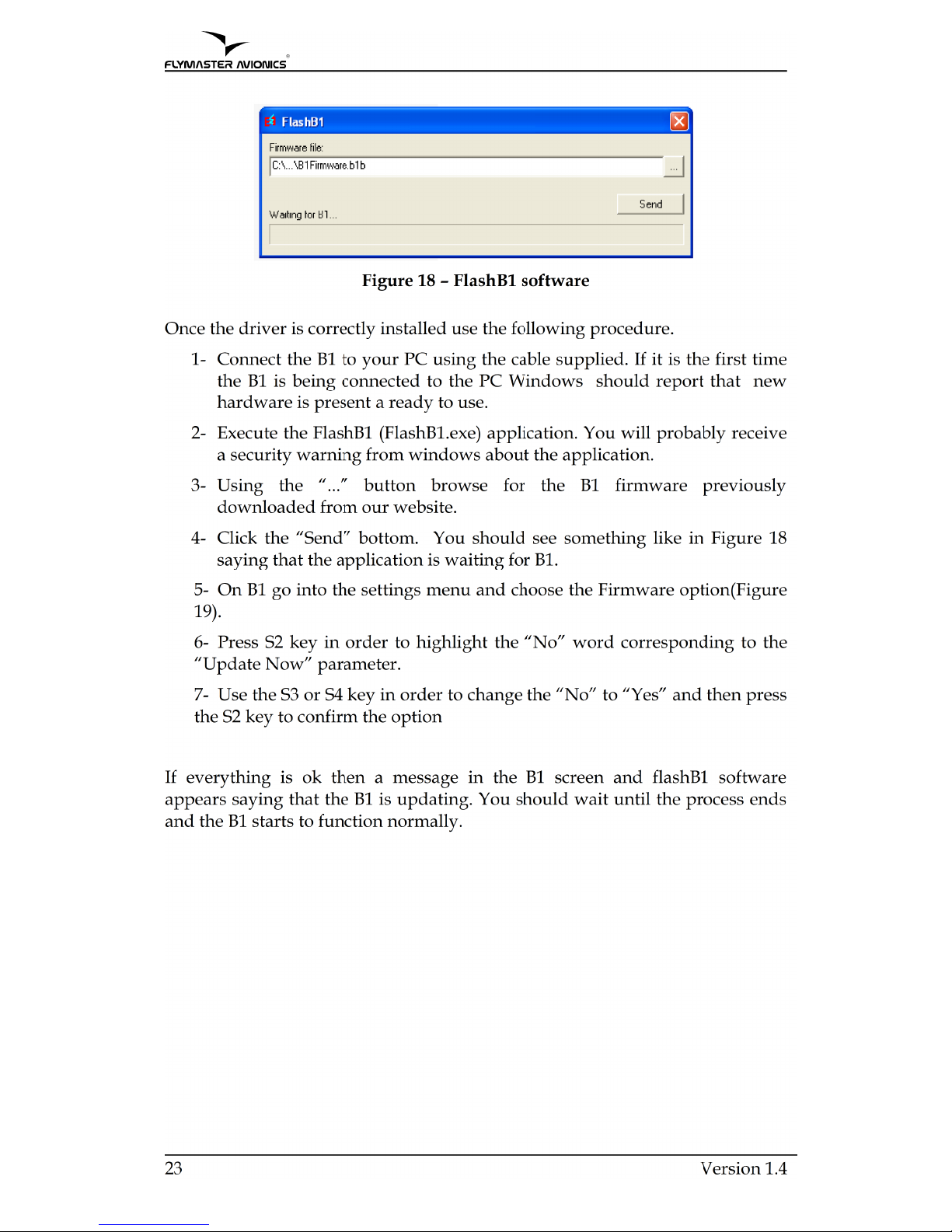
When you have all the files you can start the manual update procedure.
The first step of the updating procedure consists of installing the USB drivers
on the PC. In order to do that you should simply run the
FlymasterUSBdrivers.msi file and follow the on-screen instructions. When the
installation ends, connect the B1 to the PC and Windows should detect the B1
and automatically install the driver.
Version 1.4 22
Page 23
Page 24
B1 User Manual
Figure 19 – Firmware menu option
7. .Fail Safe firmware update
7.1. Introduction
The Fail Safe firmware update is a last resort tool if an unexpected error occurs
during the update process. This will leave the B1 with incorrect or incomplete
firmware, rendering the use of the settings menu inoperable.
Note: This procedure is a last resort measure, FLYMASTER
7.2. Update procedure
To update the B1 you will need to install the B1’s USB driver which is available
on our web site, in the section downloads of the b1 variometer.
Follow the same procedure described on section 6. to install the drivers, once
they are correctly installed use the following procedure.
1- Connect the B1 to your PC using the cable supplied. If it is the first time
the B1 is being connected to the PC Windows should report that new
hardware is present a ready to use.
2. Execute the FlashB1 application.
3. Select the B1Firmware.b1b file previously downloaded from the web site.
4. Push the “Send” button.
5. Hold the “Menu” button on your B1, and insert a toothpick into the reset
orifice on just above the USB connector on the B1 in such a way as to
reset the B1.
Version 1.4 24
Page 25

6. Release the reset button but do not release the the “Menu” button. If the
message “Erasing memory…”is shown in FlashB1 you may release the
“Menu” button, if not press and release the reset button again until the
message is shown. Note that the reset button is a small switch inside the
B1, you should feel it click.
7. Wait until you see the message “Complete” on the FlashB1 ,and B1 starts
to function normally.
25 Version 1.4
 Loading...