

Flyitalia MD 3 RIDER Aircraft Maintenance Manual

!!!!!!!!!!!!
AIRCRAFT MAINTENANCE
MANUAL
Flyitalia S.r.l tel.: +39 0373978008
Via Umberto I, 51\1 fax.: +39 037394571
26010 Dovera (CR) website.: http://www.flyitalia.it
Italy mail.: info@flyitalia.it

Aircraft maintenance manual MD3
RIDER
AIRCRAFT MAINTENANCE MANUAL
Model: MD 3 RIDER
Serial number:
Registration:
Owner: .............................................................
.............................................................
.............................................................
Aircraft maintenance manual MD3
RIDER
LIST OF THE REVISIONS AND THE REPAIRS
Ordinal
No.
Number of
document -
bulletin
It concerns to
pages No.
Date of issue: Signature :

Aircraft maintenance manual MD3
RIDER
LIST OF EFFECTIVE PAGES
Sec. Page Date Sec. Page Date Sec. Page Date Sec. Page Date
1 1-8 9/6/2005 2 2-1 9/6/2005 4 4-1 9/6/2005 5 5-1 9/6/2005
1-9 9/6/2005 2-2 9/6/2005 4-2 9/6/2005 5-2 9/6/2005
1-10 9/6/2005 2-3 9/6/2005 4-3 9/6/2005 5-3 9/6/2005
1-11 9/6/2005 2-4 9/6/2005 4-4 9/6/2005 5-4 9/6/2005
1-12 9/6/2005 2-5 9/6/2005 4-5 9/6/2005 5-5 9/6/2005
1-13 9/6/2005 2-6 9/6/2005 4-6 9/6/2005
1-14 9/6/2005 2-7 9/6/2005 4-7 9/6/2005
1-15 9/6/2005 2-8 9/6/2005 4-8 9/6/2005
1-16 9/6/2005 2-9 9/6/2005 4-9 9/6/2005
1-17 9/6/2005 2-10 9/6/2005 4-10 9/6/2005
1-18 9/6/2005 2-11 9/6/2005 4-11 9/6/2005
1-19 9/6/2005 2-12 9/6/2005 4-12 9/6/2005
1-20 9/6/2005 2-13 9/6/2005 4-13 9/6/2005
1-21 9/6/2005 2-14 9/6/2005 4-14 9/6/2005
1-22 9/6/2005 4-15 9/6/2005
1-23 9/6/2005 4-16 9/6/2005
1-24 9/6/2005 4-17 9/6/2005
1-25 9/6/2005 3 3-1 9/6/2005 4-18 9/6/2005
1-26 9/6/2005 3-2 9/6/2005 4-19 9/6/2005
1-27 9/6/2005 3-3 9/6/2005 4-20 9/6/2005
1-28 9/6/2005 3-4 9/6/2005 4-21 9/6/2005
1-29 9/6/2005 4-22 9/6/2005
1-30 9/6/2005 4-23 9/6/2005
1-31 9/6/2005 4-24 9/6/2005
1-32 9/6/2005 4-25 9/6/2005
1-32 9/6/2005 4-26 9/6/2005
1-33 9/6/2005 4-27 9/6/2005
1-34 9/6/2005 4-28 9/6/2005
1-35 9/6/2005 4-29 9/6/2005
1-36 9/6/2005
1-37 9/6/2005
1-38 9/6/2005
1-39 9/6/2005

Aircraft maintenance manual MD3
RIDER
TABLE OF CONTENTS
1. Technical descriptions....................................................................................................................8
1.1. Basic and general descriptions:..............................................................................................8
1.1.1. Designation.........................................................................................................................8
1.2. Basic Technical data...............................................................................................................9
1.2.1. Airplane views....................................................................................................................9
1.2.2. Three – view drawing......................................................................................................10
1.2.3. Basic dimensions..............................................................................................................12
1.2.4. Tires-inflation...................................................................................................................12
1.2.5. Weights ............................................................................................................12
1.2.6. Power plant.......................................................................................................................12
1.2.7. Operation fillings..............................................................................................................12
1.2.8. Propellers..........................................................................................................................13
1.3. Technical description of the plane........................................................................................14
1.3.1. Technology.......................................................................................................................14
1.3.2. General.............................................................................................................................14
1.3.3. Fuselage............................................................................................................................15
Side Canopy doors from carbon fiber with integral 3D shaped plexiglas windows on its full
surface enables great view and easy access. Doors are hinged on the front hinges and locked in
2 points on the top and bottom rear corners, equipped by classic outside handles with key
locks, and lever handles from the inside in the bottom frame....................................................17
1.3.5. Wing.................................................................................................................................18
1.3.6. Tail....................................................................................................................................20
1.4. Landing gear..........................................................................................................................21
1.4.1. General description...........................................................................................................21
1.4.2. The main landing gear......................................................................................................22
1.4.3. Nose wheel landing gear..................................................................................................23
1.4.4. Wheel brakes....................................................................................................................25
1.4.5. Wheel fairings .................................................................................................................27
1.5. Auxiliary tail skid..................................................................................................................27
1.6. Three-axis control..................................................................................................................28
1.6.1. Elevator control................................................................................................................29
1.6.2. Rudder control..................................................................................................................29
1.6.3. Ailerons control ...............................................................................................................31
1.6.4. Flaps control.....................................................................................................................32
1.6.5. Elevator trim tab control...................................................................................................34
1.7. Cockpit ...................................................................................................................................35
1.7.2. Instrument panel...............................................................................................................36
1.7.3. Standard analog flight instruments...................................................................................40
1.7.4. Digital Aveo flight instruments........................................................................................41
1.7.5. Radio – transceivers.........................................................................................................42
1.7.6. Headsets............................................................................................................................42
1.7.7. GPS...................................................................................................................................43
1.7.8. Transponder......................................................................................................................44
1.7.9. Standard engine instruments............................................................................................45
1.7.10. Digital Aveo engine istruments......................................................................................46
1.7.11. Optional instruments......................................................................................................47
1.8. Power plant............................................................................................................................48
1.8.1. The EMS – engine monitoring system ( if installed).......................................................50

Aircraft maintenance manual MD3
RIDER
1.8.2. Analog engine instruments...............................................................................................51
1.9. Fuel..........................................................................................................................................52
1.10. Oil..........................................................................................................................................52
1.11. Propeller...............................................................................................................................52
1.12. Engine bed............................................................................................................................54
1.13. Engine cowlings....................................................................................................................55
1.14. Fuel system...........................................................................................................................56
1.15. Engine lubrication system...................................................................................................58
1.16. Cooling system.....................................................................................................................59
1.17. Heating..................................................................................................................................59
1.18. Pitot-static system................................................................................................................60
1.19. Electric system.....................................................................................................................61
1.20. Placards................................................................................................................................63
2. Operation.......................................................................................................................................64
2.1. Operation outlines.................................................................................................................64
2.2. Airplane assembly..................................................................................................................65
2.2.1. Wing.................................................................................................................................65
2.2.2. Horizontal tail unit............................................................................................................67
2.2.3. Vertical tail unit................................................................................................................68
2.2.4. Landing gear.....................................................................................................................69
2.2.5. Removal and replacement of mudguards ..................70
2.2.6. Installation and relinstallation of instruments..................................................................71
2.3. Measurement of control surfaces deflections......................................................................72
2.3.1. Required deflections.........................................................................................................72
2.3.2. Aileron deflection measurement......................................................................................73
2.3.3. Flap deflection measurement............................................................................................73
2.3.4. Elevator deflections measurement....................................................................................74
2.3.5. Rudder deflection measurement.......................................................................................74
2.3.6. Trim tab deflections measurement...................................................................................75
2.4. Permissible Tolerances..........................................................................................................76
2.5. Weighing the airplane and C.G. calculation.......................................................................77
2.5.1. Empty weight determination............................................................................................77
2.5.2. Operating C. G. range calculation....................................................................................77
3. Ground handling...........................................................................................................................78
3.1. Assembling for transportation and hangaring..................................................................78
3.2. Unlocking, opening and turning up the rear baggage fairing .........................................78
3.3. Disconnecting aileron controls and front wing hinges......................................................78
3.4. Folding the wings ................................................................................................................79
3.5. Parking..................................................................................................................................79
3.5.1. General............................................................................................................................79
3.5.2. Pressure sensor plug of the airspeed indicator................................................................79
3.6. Mooring.................................................................................................................................80
3.7. Hangaring..............................................................................................................................81
3.8. Towing ...................................................................................................................................81
4. Maintenance....................................................................................................................................1
4.1. Overall maintenance survey...................................................................................................1
4.2. Pre-flight inspection................................................................................................................1
4.2.1. Direction of pre-flight inspection.......................................................................................1
4.2.2. Steps of pre-flight inspection.............................................................................................2
4.3. Post-flight inspection...............................................................................................................3

Aircraft maintenance manual MD3
RIDER
4.4. Periodical inspection................................................................................................................3
4.4.1. Periodical inspection intervals............................................................................................3
4.4.2. Periodical inspections Sign off sheets................................................................................3
4.4.3. Periodical inspections – events...........................................................................................4
4.5. Fluids.......................................................................................................................................13
4.5.1. Engine oil.........................................................................................................................14
4.5.2. Coolant.............................................................................................................................14
4.5.3. Brake fluid........................................................................................................................15
4.5.4. Fuel...................................................................................................................................16
4.6. Lubrication.............................................................................................................................17
4.6.1. Lubrication fundamentals.................................................................................................17
4.6.2. Recommended lubricants.................................................................................................17
4.6.3. Lubrication points.............................................................................................................18
4.7. Mechanism adjustments........................................................................................................19
4.7.1. Torque moments...............................................................................................................19
4.8. Brake system efficiency adjustment.....................................................................................21
4.8.1. Brake pad replacement.....................................................................................................21
4.8.2. Bleeding............................................................................................................................22
4.9. Control surfaces deflection setting.......................................................................................23
4.9.1. Aileron deflection adjustment..........................................................................................23
4.9.2. Elevator deflection adjustment.........................................................................................23
4.9.3. Rudder deflection adjustment...........................................................................................23
4.9.4. Trim deflection adjustment...............................................................................................23
4.9.5. Flap deflection adjustment...............................................................................................23
4.10. Steerable nosewheel landing gear adjustment..................................................................25
4.11. Engine idle adjustment........................................................................................................25
4.12. Tire inflation pressure.........................................................................................................25
4.13. Door closing mechanism adjusting ...................................................................................26
4.14. Cleaning and care................................................................................................................27
4.14.1. Airplane care outlines.....................................................................................................27
4.14.2. External surfaces cleaning..............................................................................................27
4.14.3. Interior cleaning.............................................................................................................27
4.14.4. Cockpit canopy cleaning................................................................................................27
4.15. Winter operation..................................................................................................................28
4.15.1. General ..........................................................................................................................28
4.15.2. Preparing the aircraft for winter operation.....................................................................28
4.16. Necessary maintenance tools..............................................................................................29
4.17. Engine maintenance............................................................................................................29
4.18. Propeller maintenance.........................................................................................................29
5. Appendices......................................................................................................................................1
5.1. Record about the checking of control surfaces and tension of airplane cables.................2
5.2. Record about the weighting and location of gravity for MD-3 RIDER aircraft...............3
5.3. Record about the weighting and location of gravity for MD-3 RIDER aircraft...............3
5.4. Flight Test Record for MD-3 RIDER aircraft.......................................................................5

1.Technical descriptions
1.1.Basic and general descriptions:
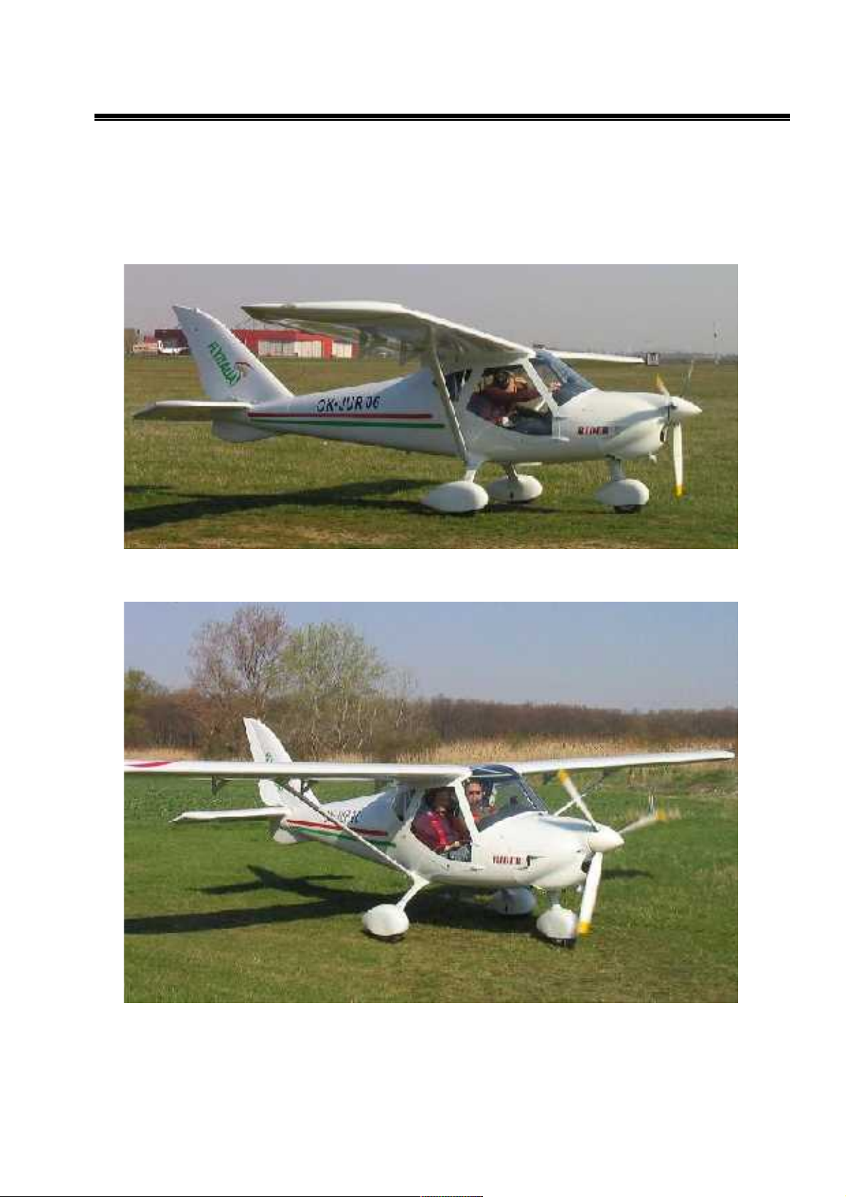
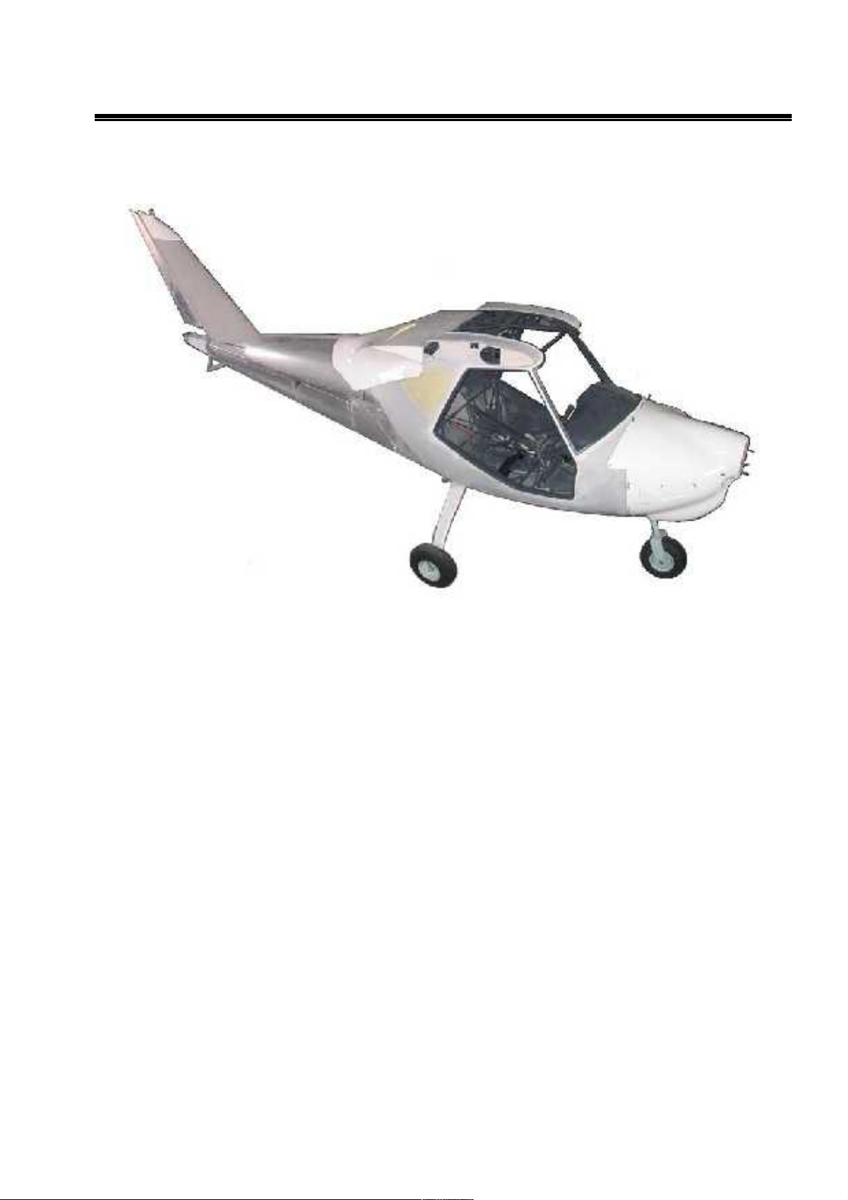
Classical all-metal MD3 Rider with high-wing with side-by-side seats. The aircraft is equipped with
tricycle landing gear. Standard powerplant consist of, 4 cylinder, 4 stroke Rotax 912S or UL
(80,100hp) engine and three blade propeller. MD3 conforms to Czech UL-2 and Germany BFUDULV requirements for “sport flying vehicles”.
1.1.1.Designation
MD3 Rider designed to be ideal for training, CROSS-COUNTRY flying and flying for fun.
Aircraft maintenance manual MD3
RIDER
1.2. Basic Technical data
1.2.1.Airplane views
DIMENSIONS :
9

Aircraft maintenance manual MD3
RIDER
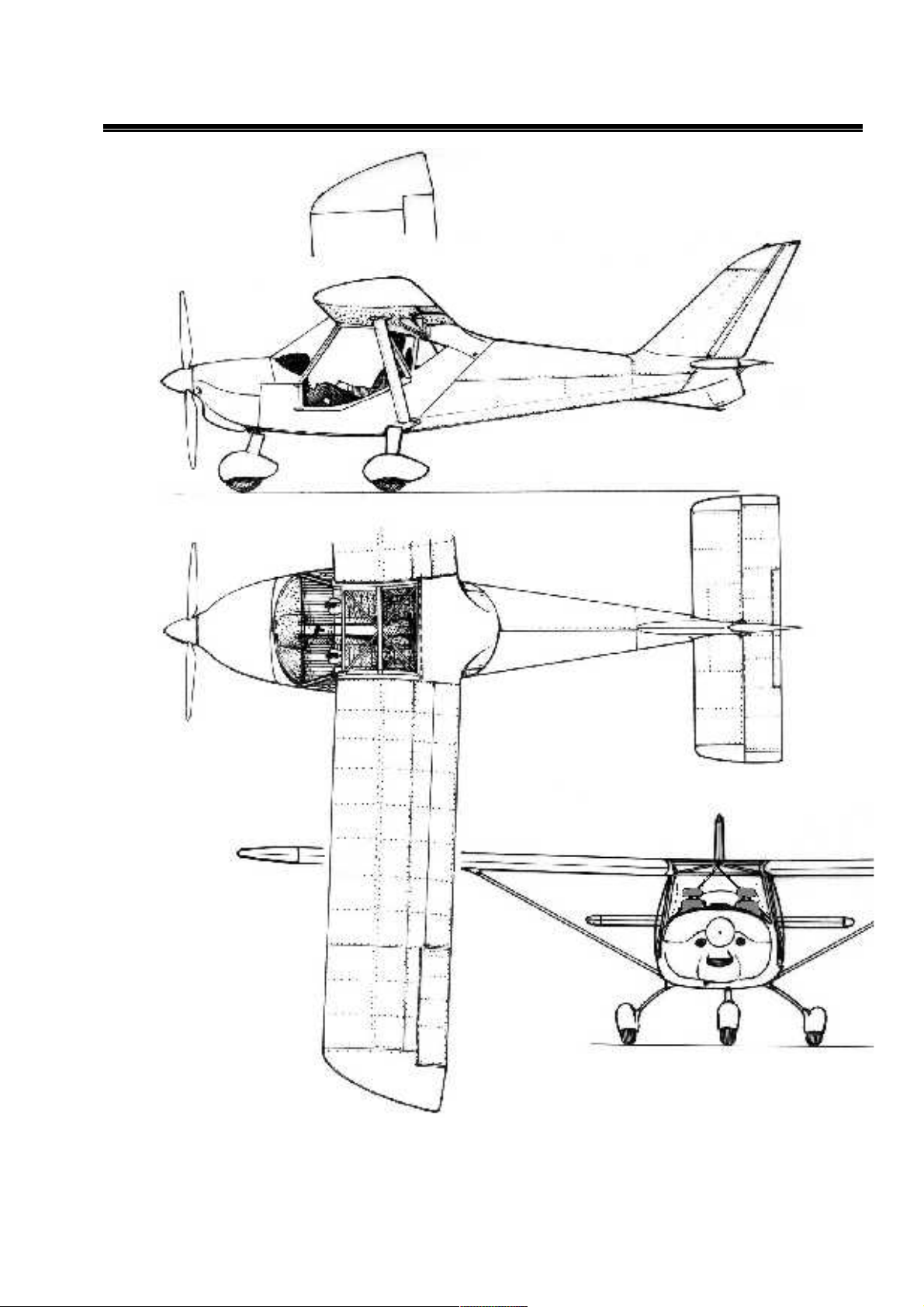
1.2.2. Three – view drawing
10
Aircraft maintenance manual MD3
RIDER
11

Aircraft maintenance manual MD3
RIDER
1.2.3.Basic dimensions
Wing span 9.0 m 28,5 ft
Length 5.9 m 19,3 ft
Height 2.3 m 7,5 ft
Wing area 9.9 m
2
106,6 sq ft
Forward swept wing: -3
1.2.4.Tires-inflation
Nose landing gear - 180 +20 kPa / 26,5 + 3 psi
Main landing gear - 180 +20 kPa / 26,5 + 3 psi
1.2.5.Weights
MD3 RIDER MD3 RIDER UL MD3 RIDER 914
Empty weight 295 kg / lb 276 kg / lb 297 kg / lb
Maximum take-off weight 450 kg / 992 lb 450 kg /992 lb 450 kg / 992 lb
Strength limit MTOW 480 kg / 480 kg / 480 kg /
Maximum load factor +4 / -2 (ultimate + 6 / -3)
1.2.6.Power plant
1.2.6.1.Engine ROTAX
912 S 912 UL 914 UL
Maximum power 100HP / 73,5 kW 80 HP / 59,6 kW 115 HP / 85,7 kW
Time limited max. 5 min. max. 5 min.
For 5800 rpm 5800 rpm
Without limit 95 HP / 69,0 kW 100 HP / 74,5 kW
For 5500 rpm 5800 rpm 5500 rpm
Cylinder volume 1352ccm 1211ccm 1211ccm
Compression ratio 10,5 : 1 9,0 : 1
Dry weight 56,6 kg 54 kg 61,1 kg
Ignition unit DUCATI double CDI
Carburetor 2 x BING 64-3
1.2.7.Operation fillings
Fuel 94 l automotive petrol SUPER - BA 96 in two 47 l integral wing fuel tanks
Gear box oil API-GL5 (0, 5 l )
12

Aircraft maintenance manual MD3
RIDER
1.2.8.Propellers
1.2.8.1.Standard:
WOODCOMP SR 200 B - wooden 3-blade on the ground adjustable
1.68 m
Optional: Klassic 160/3/R - composite on the ground adjustable 3-blade 1.6 m
Winglet 165/3/R - on the ground adjustable 3-blade 1.65 m
Varia 170/2R - composite in the flight variable pitch 2-blade 1.70 m
SR 2000 XA - in flight variable pitch wooden 1.70 m
13
Aircraft maintenance manual MD3
RIDER
1.3.Technical description of the plane
1.3.1.Technology
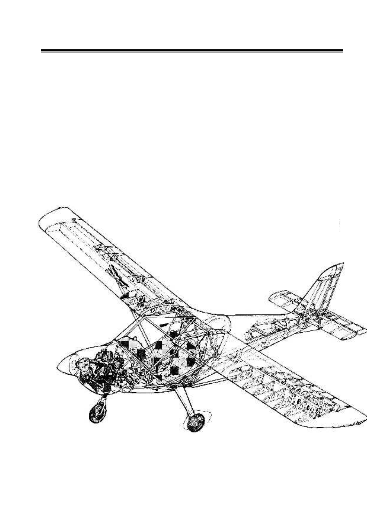
All-metal semi-monocoque airframe, primary glued and riveted from aluminum alloy sheets
by blind rivets.
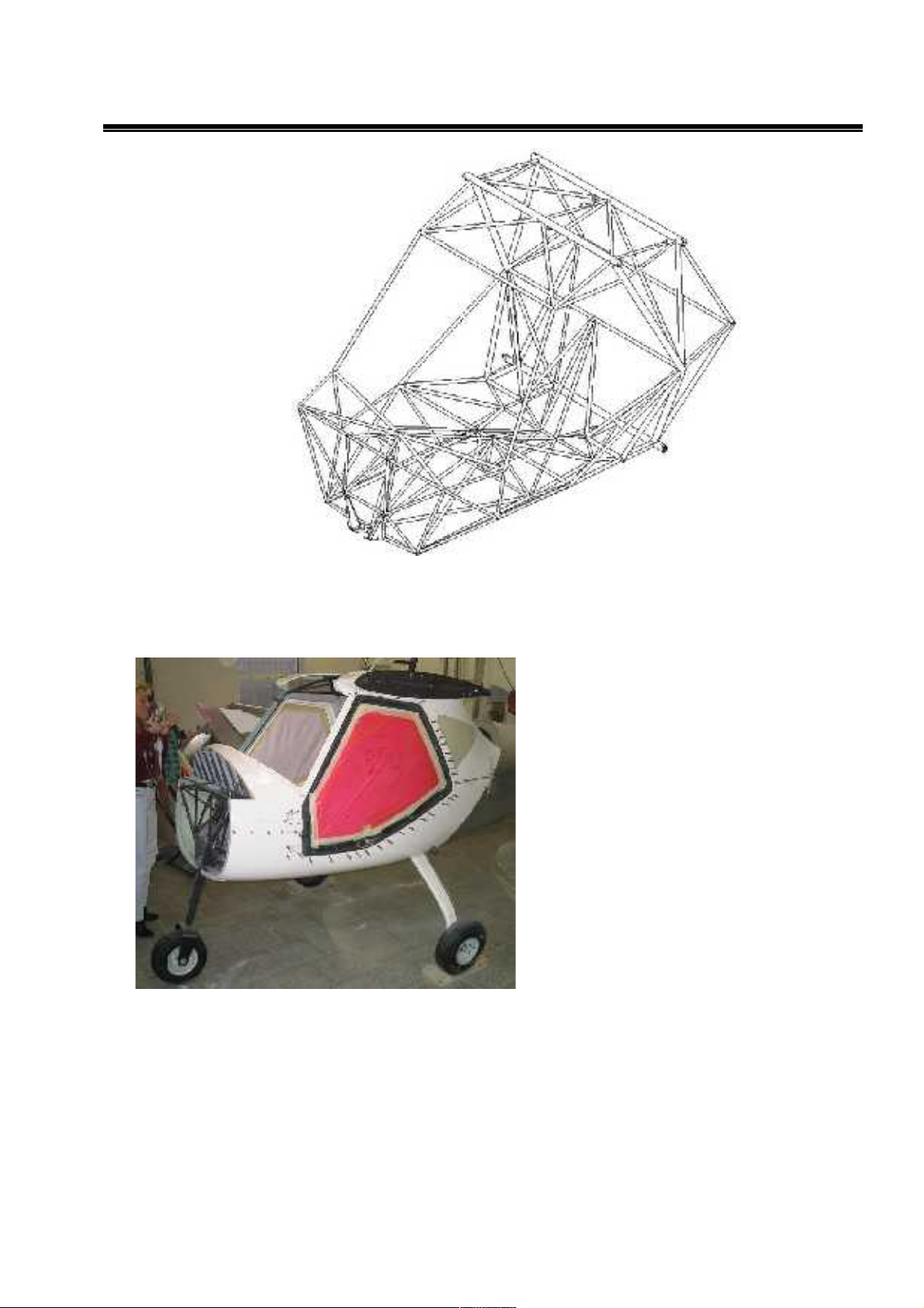
1.3.2.General
The MD3 airframe is of semi-monocoque construction glued and riveted from aluminum alloy
sheets by blind rivets. Some non supporting parts are made from fiberglass.
Fig.: MD3 Rider aircraft construction
14
Aircraft maintenance manual MD3
RIDER
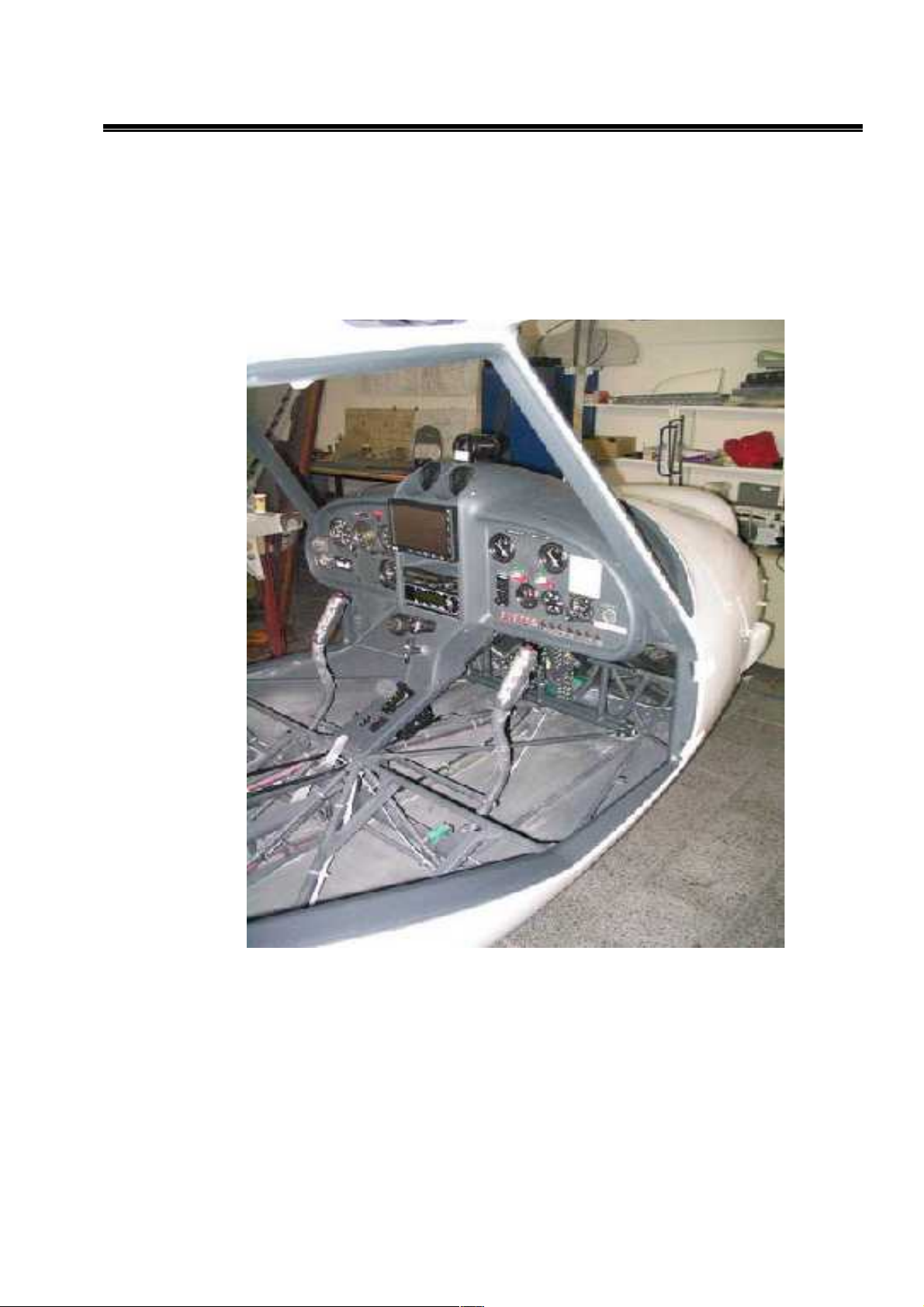
1.3.3.Fuselage
1.3.3.1.Fuselage cockpit cage
FUSELAGE COCKPIT CAGE is welded from steel tubes. Its structure cover firewall,
engine mounting hinges and front wheel bracket in the front, wing struts and main gear
hinges on its sides and instrument panel frame and seats brackets, safety belts, arm-rest
and control levers hinges in the middle. On the rear part it has 4 rear fuselage part hinges.
On the top welded cage carries wing hinges, prepared for its folding and brackets of
aileron and flap controls.
15
Aircraft maintenance manual MD3
RIDER
1.3.3.2.Cockpit Fairing
Cockpit fairing is produced from glass
fiber composite, glued on the tubes and
sheets of airframe and covers firewall,
instrument panel including air vents,
windshield frame in the front, conection
to the wings in the top and door frames
on the sides. In the rear COCKPIT
FAIRING is equipped by foldable cargo
compartment doors, needed to be
folded for wing folding too.
1.3.3.3.Rear fuselage part cone
Rear fuselage part cone is riveted from aluminum alloy sheets with integral fin and with
horizontal tail hinges on the rear “floor” and rudder hinges on the fin beam. Aluminum
alloy cone is finished by composite fairings with aerodynamically smooth transition
between horizontal and vertical areas and creates small bottom fin with tail-bump.
Fig.:Fuselage cockpit cage
16
Aircraft maintenance manual MD3
RIDER
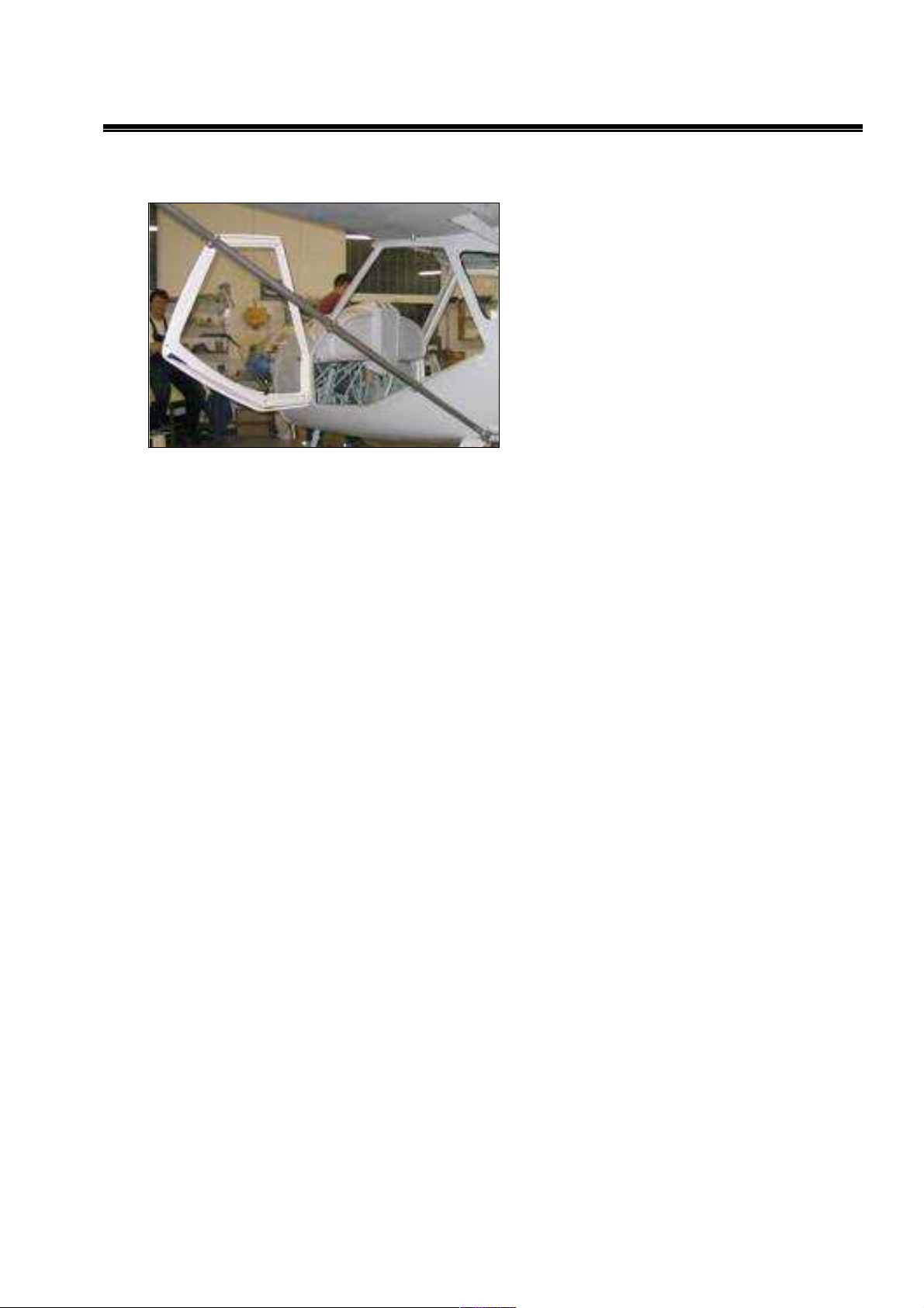
1.3.3.4.Side Canopy doors
Side Canopy doors from carbon fiber with
integral 3D shaped plexiglas windows on
its full surface enables great view and
easy access. Doors are hinged on the
front hinges and locked in 2 points on the
top and bottom rear corners, equipped by
classic outside handles with key locks,
and lever handles from the inside in the
bottom frame.
17
Aircraft maintenance manual MD3
RIDER
1.3.4.
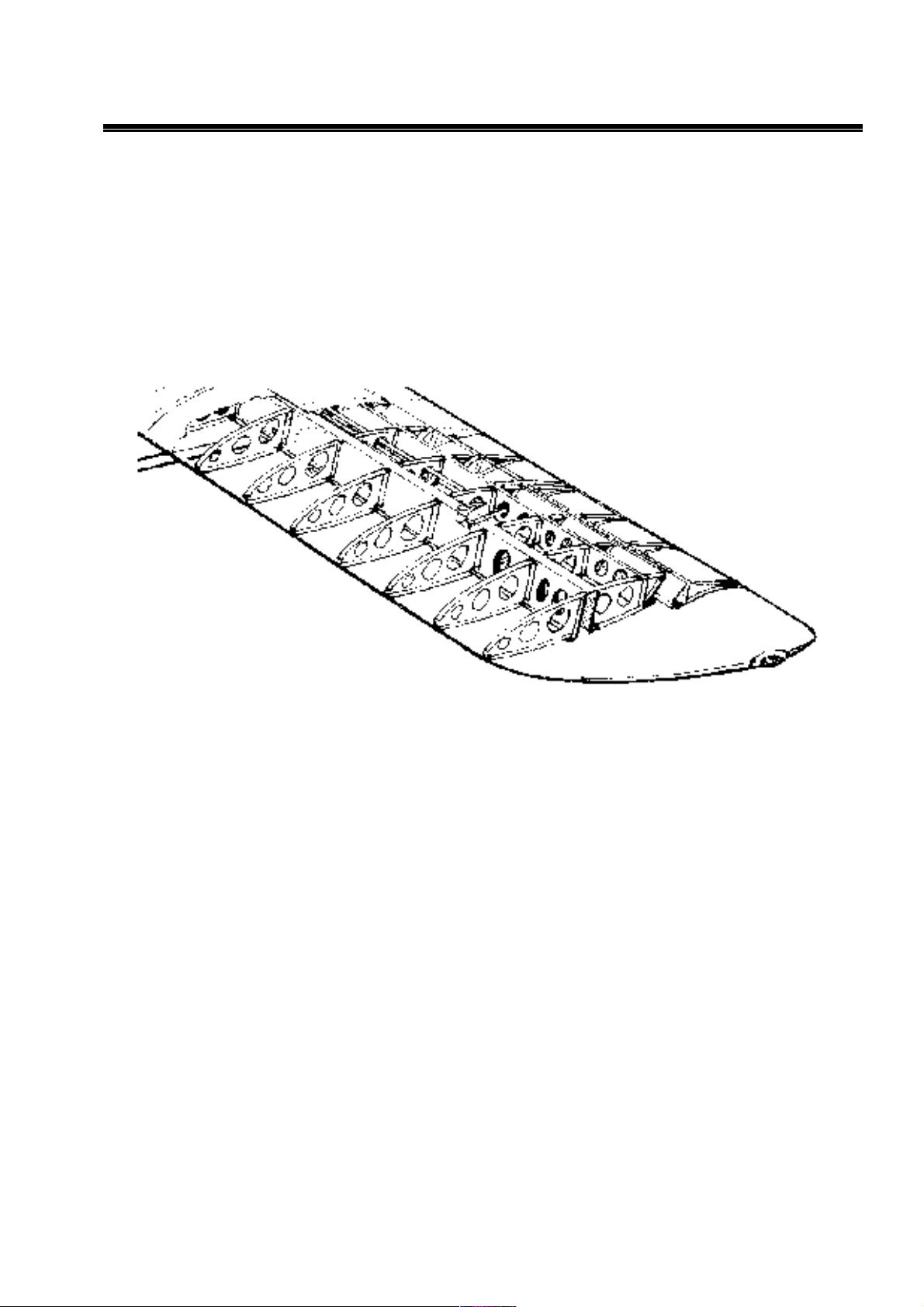
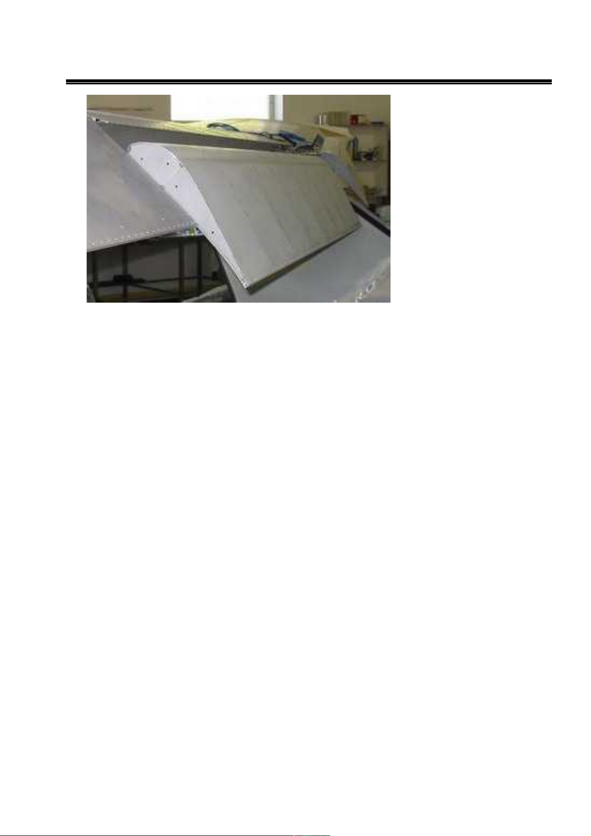
1.3.5.Wing
ALL METAL WINGS with simple aerodynamically shaped strut and efficient MS(1)-0313
airfoil with OMEGA-beam pressed ribs and integral fuel tanks 92 liters. Ailerons and large
flaps with 15o, 30o and 38o deflection are hinged on rear help-beam. Large aerodynamically
shaped wingtips increase wing efficiency. There is possibility to tilt wings backward to tail.
1.3.5.1.Ailerons
40% 1:1,5 differential ailerons are connected to upper side of airfoil with piano-hinge and
and driven through control lever riveted to root rib
1.3.5.2.Flaps
Fowler flaps are connected to wing over three arms and are electrically driven (BETAKOM
system) over tube in two points root and middle arm section. They have three positions 15°
(start) 30° (landing) and 38° (short landing)
Fig.: Left wing
18
Aircraft maintenance manual MD3
RIDER
Fig.: Flaps in landing position
19
Aircraft maintenance manual MD3
RIDER
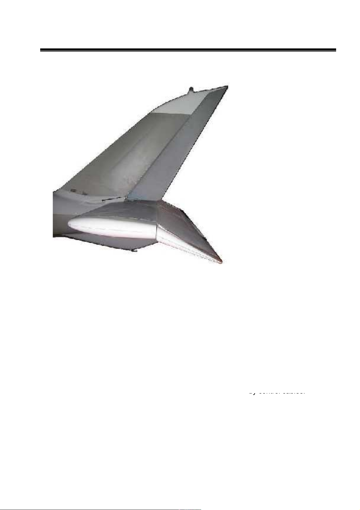
1.3.6.Tail
Classic-type all-metal TAIL has
symmetrical NACA 12%
profile. Horizontal Tail Unit
(HTU) consists of stabilizer
and elevator with trim tab. The
semi monocoque construction
consists of duralumin ribs,
spars and skin. Construction is
riveted by blind rivets and
glued by Efimastic PU50.
Trapezoidal Vertical Tail Unit
(VTU) consists of fin and
rudder. The rudder is attached
on the fin by two hinges. The
frame of VTU is composed of
metal sheet spar and
duralumin skin.(riveted and
glued by Efimastic PU50)
1.3.6.1.Stabilizer
Classic-type all-metal horizontal
tail glued by Emfimastic PU50 and riveted by blind rivets from aluminum alloy sheets and
pressed ribs and bended beams has symmetrical 12% airfoil NACA 0012. Stabilizer is
connected to fuselage over 2+2 connection points on auxiliary front and main rear spar.
Joint brackets on fuselage are riveted with solid rivets.
1.3.6.2.Elevator
The same technology rectangular shape elevator (with pressed 2024T3 aluminum alloy ribs and
skin) is connected with stabilizer through on the airfoil (rear beam) top fixed piano hinge and
has electrically controlled integral TRIM-TAB as a standard.
1.3.6.3.Fin
Fin with symmetrical 12% airfoil NACA 0012 is integral part of Rear fuselage part structure.
Rudder is hinged in two hinges and controlled from bottom - by control cables.
In the top of fin-tip there is located bracket for optional tail strobe light placing.
1.3.6.4.Rudder
The rudder is the trapezoidal shape and formed with a duralumin spar and skin and
attached with two hinges at the fin.
Rudder upper tip is formed with fiberglass cover.
Fig.: Aircraft tail
20
Aircraft maintenance manual MD3
RIDER
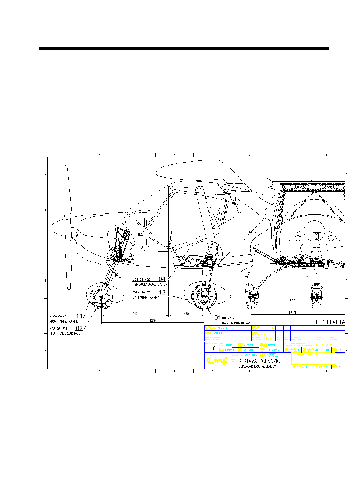
1.4.Landing gear
1.4.1.General description
The aircraft is equipped with fixed, tricycle landing gear.
The nose wheel is steerable, composite main gear is equipped with hydraulic brakes.
MD3-03-000
Fig.:Tricycle landing gear
21
Aircraft maintenance manual MD3
RIDER
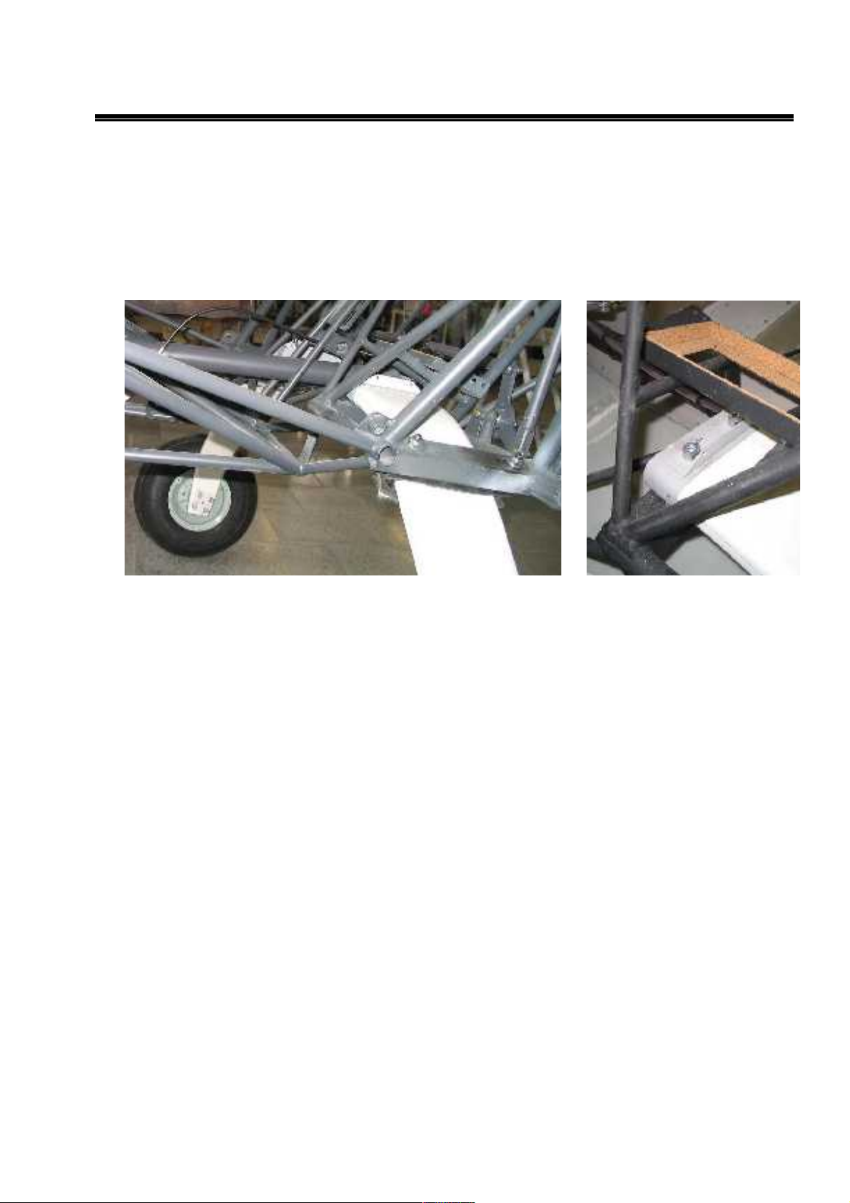
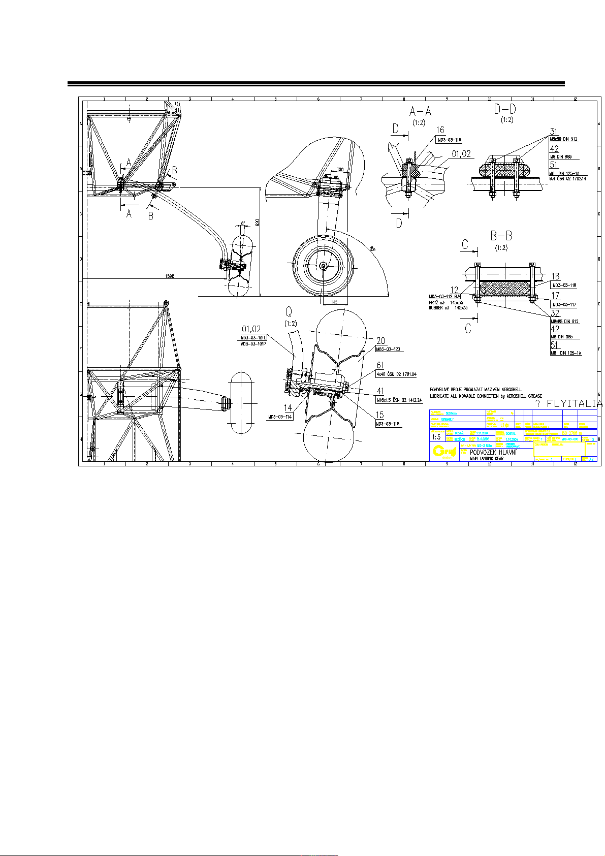
1.4.2.The main landing gear
The main landing gear consists of right and left composite legs which are fixed in two
brackets inside fuselage welded cage. The legs are formed from fiberglass springs. The
main wheels 14x4” are equipped with hydraulic disc brakes (Aerospol) controlled by leveler
on the central column.
Fig.:Fixing of the main landing gear leg
22
Aircraft maintenance manual MD3
RIDER
MD3-03-100
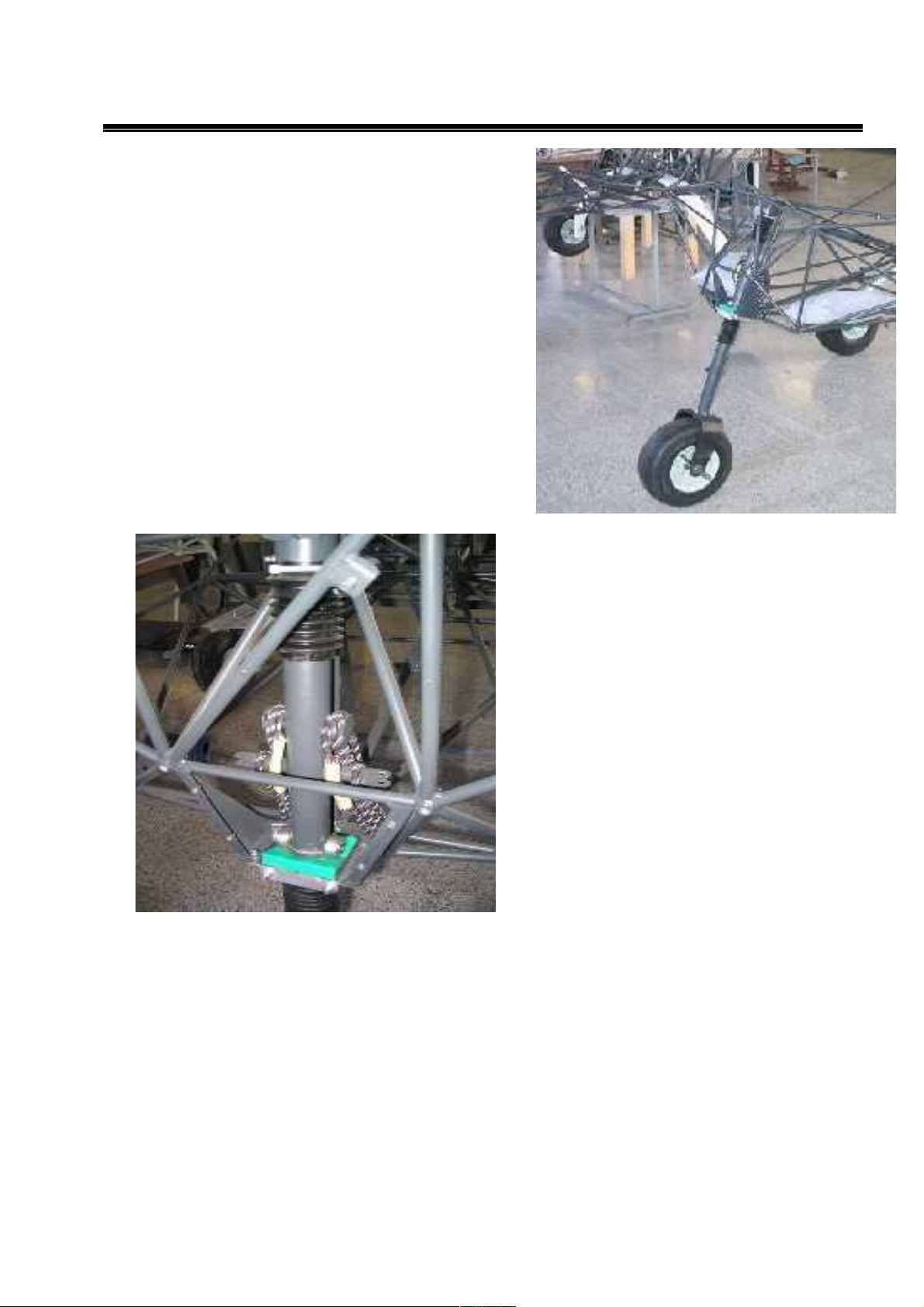
1.4.3.Nose wheel landing gear
Steerable nose landing gear consists of front landing gear leg. Rubber cable shock
absorbing unit and suspension stop. The nose leg is made from steel tube. Fork is from
carbon fibers. Two rods are used for the leg steering by the control pedals. Wheel 13x4”.
Fig.:Main landing gear
23
Aircraft maintenance manual MD3
RIDER
Fig.:Front landing gear leg with
avional fork
Fig.:Rubber rope suspension unit
24
Aircraft maintenance manual MD3
RIDER
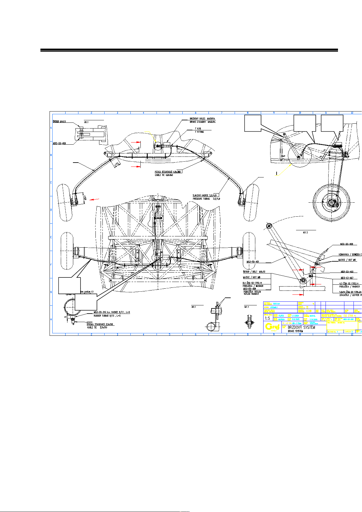
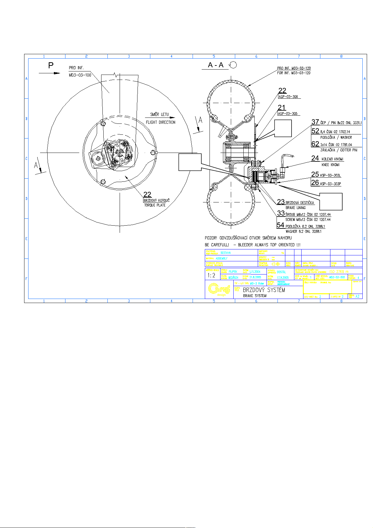
1.4.4.Wheel brakes
Both wheels on the main landing gear are equipped with hydraulic disc brakes. The brake
system consists of the brake handle in the middle column, hydraulic brake master cylinder,
plastic hoses, brake caliper with hydraulic brake cylinder, brake pads and the brake discs.
MD3-03-400
9
ᄅ FLYITALIA
P2
31
6
DETAIL II
8
41
12
1
DETAIL I
51
D
7
61
52
42
C
19
9
32
3
C
D
2
15
B
II
C - C
19
B
B - B
D - D
13
13
10
18
2
3
1 2 3
25
Aircraft maintenance manual MD3
RIDER
MD3-03-400
ᄅ FLYITALIA
5
6
4
Fig.: Brake system
1. brake handle
2. plastic hoses
3. hydraulic master cylinder
4. brake caliper with brake cylinder
5. brake pads
6. brake disc
26
Aircraft maintenance manual MD3
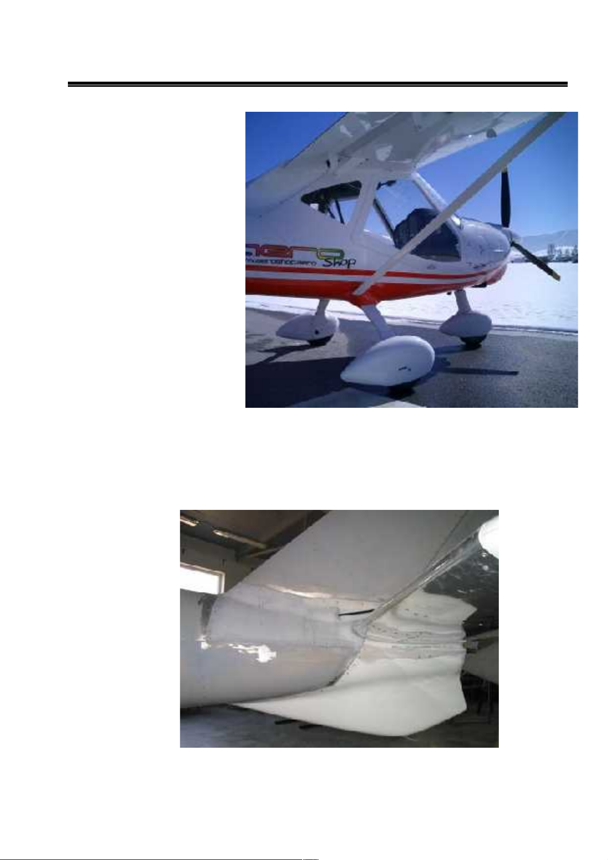
RIDER
1.4.5.Wheel fairings
All landing gear wheels
can be optionally equipped
by composite wheel
fairings.
1.5.Auxiliary tail skid
Auxiliary tail skid protects tail of aircraft from inadvertent damage during tail down landing
conditions. ATS is made from aluminum alloy pressed U profiles and covered by fiberglass
formed cover – with shape of auxiliary bottom fin.
Fig.: Auxiliary tail skid
27
Aircraft maintenance manual MD3
RIDER
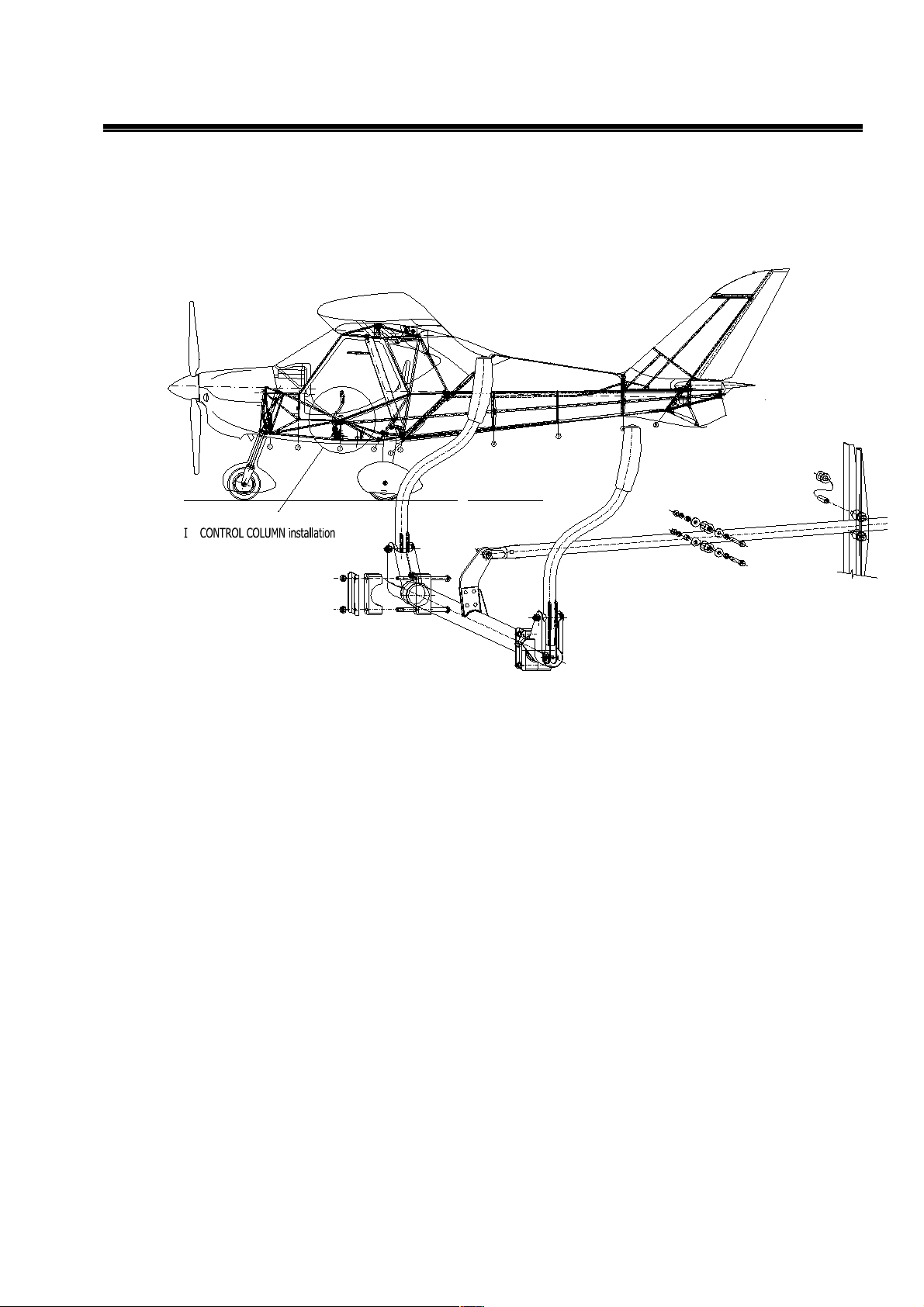
1.6.Three-axis control
Full dual control, with classic joysticks between pilot legs and pedals full controllable for both
pilots..Flap handle, trim handle, throttle and choke are placed on the central column.
Fig.:Dual control system
28
Aircraft maintenance manual MD3
RIDER
1.6.1.Elevator control
Elevator is controlled by joysticks, fixed in control column through one rod only guided in rod pulleys
fixed in metal brackets in welded cage and rear fuselage cone and connected directly with elevator
lever.
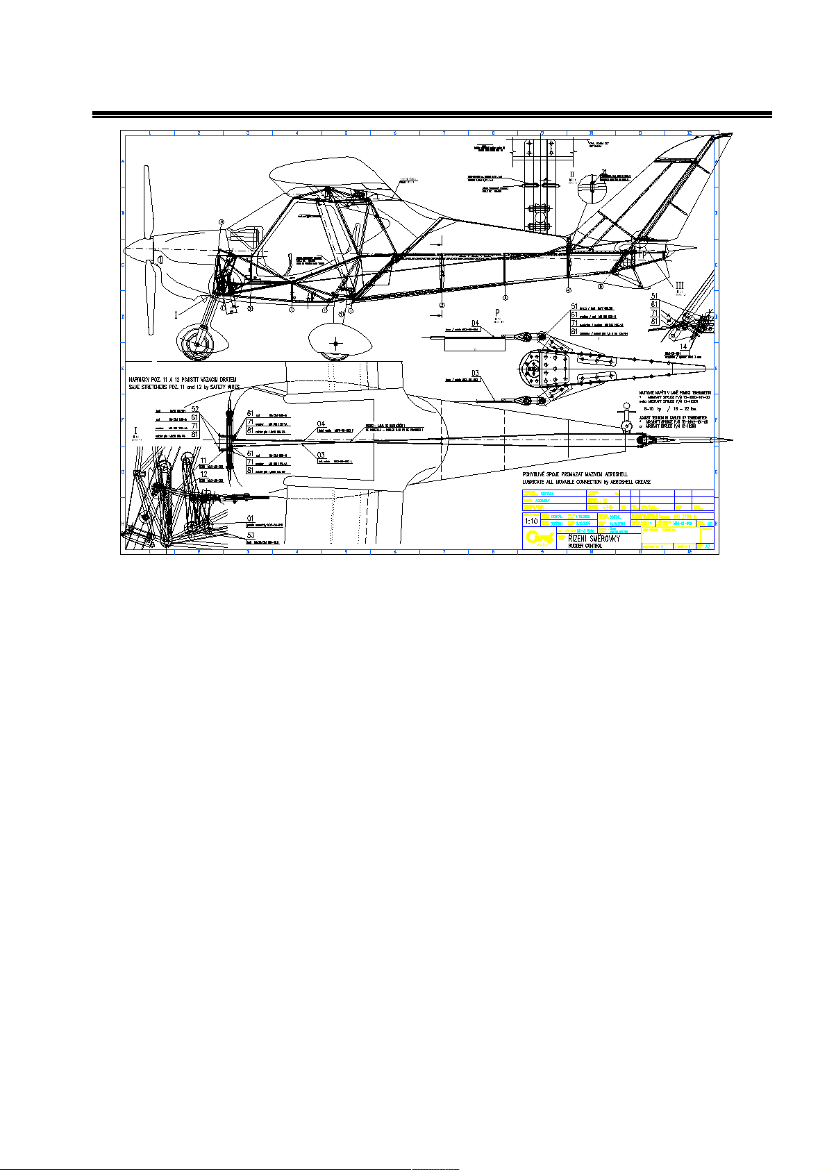
1.6.2.Rudder control
Rudder is controlled by wires in plastic slide tubes and connected through front undercarriage leg
control levers. Stretchers are located in the front – accessible from the cockpit.
29
Aircraft maintenance manual MD3
RIDER
MD3-09-500
ᄅ FLYITALIA
B
B
31
21
B - B
31
30
 Loading...