


Copy Right 2014 All Rights Reserved by FLYINGVOICE TECHNOLOG LIMITED
V1.0
The page 1 of 62
Revision time: 2014-12-11 9:00
The G504/G508
High Speed Router
User’sGuide
V1.0

Copy Right 2014 All Rights Reserved by FLYINGVOICE TECHNOLOG LIMITED
V1.0
The page 2 of 62
Revision time: 2014-12-11 9:00
Table of Contents
1 Preface............................................................................................................................................................................................................................................................................. 4
1.1 Declaration of Conformity ................................................................................................................................................................................................................................ 4
1.1.1 Part 15 FCC Rules ..................................................................................................................................................................................................................................... 4
1.1.2 Class B Digital Device or Perpheral .......................................................................................................................................................................................................... 4
1.2 GNU GPL Information ..................................................................................................................................................................................................................................... 5
2 Overview ......................................................................................................................................................................................................................................................................... 6
2.1 G504 and G508 ................................................................................................................................................................................................................................................. 6
2.2 LED Indicators .................................................................................................................................................................................................................................................. 7
2.2.1 G504 LED Indicators ................................................................................................................................................................................................................................. 7
2.2.2 G508LED Indicators .................................................................................................................................................................................................................................. 8
2.3 Hardware Installation ........................................................................................................................................................................................................................................ 9
2.4 Voice Prompt ................................................................................................................................................................................................................................................... 10
2.5 Configuring Basic Settings ............................................................................................................................................................................................................................. 13
2.6 Two-LevelManagement .................................................................................................................................................................................................................................. 13
2.7 AccessingWebPage ......................................................................................................................................................................................................................................... 13
2.7.1 From LAN port ........................................................................................................................................................................................................................................ 13
2.7.2 From WAN port ....................................................................................................................................................................................................................................... 14
2.8 WEB Page ....................................................................................................................................................................................................................................................... 15
2.9 Setting up the Time Zone................................................................................................................................................................................................................................ 16
2.10 Setting up the Internet Connection ................................................................................................................................................................................................................. 16
2.11 Register ........................................................................................................................................................................................................................................................... 17
2.11.1 Get the Accounts ...................................................................................................................................................................................................................................... 17
2.11.2 Connections.............................................................................................................................................................................................................................................. 17
2.11.3 Configuration SIP from Webpage ............................................................................................................................................................................................................ 18
2.11.4 View the Register Status .......................................................................................................................................................................................................................... 19
3 Web Configuration ........................................................................................................................................................................................................................................................ 20
3.1 Status ............................................................................................................................................................................................................................................................... 20
3.2 Network........................................................................................................................................................................................................................................................... 21
3.2.1 WAN......................................................................................................................................................................................................................................................... 21
3.2.2 LAN ......................................................................................................................................................................................................................................................... 26
3.2.3 MAC Clone .............................................................................................................................................................................................................................................. 27
3.2.4 VPN.......................................................................................................................................................................................................................................................... 28
3.2.5 DMZ......................................................................................................................................................................................................................................................... 28
3.2.6 DDNS....................................................................................................................................................................................................................................................... 29
3.2.7 Port Forward ............................................................................................................................................................................................................................................ 29
3.2.8 Routing..................................................................................................................................................................................................................................................... 30
3.3 SIP Account..................................................................................................................................................................................................................................................... 31
3.3.1 Account .................................................................................................................................................................................................................................................... 31
3.3.2 FXS Setting .............................................................................................................................................................................................................................................. 32
3.3.3 SIP Settings .............................................................................................................................................................................................................................................. 37
3.3.4 VoIP Qos .................................................................................................................................................................................................................................................. 38

Copy Right 2014 All Rights Reserved by FLYINGVOICE TECHNOLOG LIMITED
V1.0
The page 3 of 62
Revision time: 2014-12-11 9:00
3.4 Phone............................................................................................................................................................................................................................................................... 39
3.5 Administration ................................................................................................................................................................................................................................................ 47
3.5.1 Management............................................................................................................................................................................................................................................. 47
3.5.2 Firmware Upgrade ................................................................................................................................................................................................................................... 50
3.5.3 Certification ............................................................................................................................................................................................................................................. 51
3.5.4 Provision .................................................................................................................................................................................................................................................. 51
3.5.5 SNMP....................................................................................................................................................................................................................................................... 53
3.5.6 TR069....................................................................................................................................................................................................................................................... 53
3.5.7 Diagnosis.................................................................................................................................................................................................................................................. 54
3.6 Logout ............................................................................................................................................................................................................................................................. 55
3.7 Reboot ............................................................................................................................................................................................................................................................. 55
4 Functions ....................................................................................................................................................................................................................................................................... 56
4.1 Making Calls ................................................................................................................................................................................................................................................... 56
4.2 Call Waiting .................................................................................................................................................................................................................................................... 56
4.3 Call Hold ......................................................................................................................................................................................................................................................... 56
4.4 Call Transferring ............................................................................................................................................................................................................................................. 56
4.4.1 Blind Transfer .......................................................................................................................................................................................................................................... 56
4.4.2 Attended Transfer..................................................................................................................................................................................................................................... 57
4.5 3-way conference call ..................................................................................................................................................................................................................................... 57
4.6 Call Forwarding .............................................................................................................................................................................................................................................. 57
4.7 Direct IP calls .................................................................................................................................................................................................................................................. 57
4.8 Speed dialing................................................................................................................................................................................................................................................... 58
4.9 Hotline............................................................................................................................................................................................................................................................. 58
5 Trouble shooting of the guide ....................................................................................................................................................................................................................................... 59
5.1 Setting your PC gets IP automatically ............................................................................................................................................................................................................ 59
5.2 Can not connect to the configuration Website ................................................................................................................................................................................................ 60
5.3 Fast Bridge Setting.......................................................................................................................................................................................................................................... 60
5.4 Password Control ............................................................................................................................................................................................................................................ 61
5.5 Forget the Password ........................................................................................................................................................................................................................................ 62

Copy Right 2014 All Rights Reserved by FLYINGVOICE TECHNOLOG LIMITED
V1.0
The page 4 of 62
Revision time: 2014-12-11 9:00
1 Preface
Thanks for choosing G504/G508 router with VoIP. This product will allow you to make ATA call using your broadband connection.
This manual provides basic information on how to install and connect G504/G508 router with VoIP to the Internet. It also includes features
and functions of router with VoIP components, and how to use it correctly.
Before you can connect G504/G508 to the Internet and use it, you must have a high-speed broadband connection installed. A high-speed
connection includes environments such as DSL, cable modem, and a leased line.
G504/G508 router with VoIP is a stand-alone device, which requires no PC to make Internet calls. This product guarantees clear and reliable
voice quality on Internet, which is fully compatible with SIP industry standard and able to interoperate with many other SIP devices and
software on the market.
1.1 Declaration of Conformity
1.1.1 Part 15 FCC Rules
This device complies with Part 15 of the FCC Rules. Operation is subject to the following two conditions:
This device may not cause harmful interference, and
This device must accept any interference received, including interference that may cause undesired operation.
1.1.2 Class B Digital Device or Perpheral
Note: Changes or modifications not expressly approved by the party responsible for compliance could void the user‟s authority to ope rate the
equipment.
This equipment has been tested and found to comply with the limits for a Class B digital device, pursuant to Part 15 of the FCC Rules. These
limits are designed to provide reasonable protection against harmful interference in a residential installation. This equipme nt generates, uses
and can radiate radio frequency energy and, if not installed and used in accordance with the instructions, may cause harmful interference to
radio communications. However, there is no guarantee that interference will not occur in a particular installation.
If this equipment does cause harmful interference to radio or television reception, which can be determined by turning the equipment off and
on, the user is encouraged to try to correct the interference by one or more of the following measures:
1. Reorient or relocate the receiving antenna.
2. ncrease the separation between the equipment and receiver.

Copy Right 2014 All Rights Reserved by FLYINGVOICE TECHNOLOG LIMITED
V1.0
The page 5 of 62
Revision time: 2014-12-11 9:00
3. Connect the equipment into an outlet on a circuit different from that to which the receiver is connected.
4. Consult the dealer or an experienced radio/TV technician for help.
1.2 GNU GPL Information
G504/G508 firmware contains third-party software under the GNU General Public License(GPL). FLYINGVOICE uses software under the
specific terms of the GPL. Please refer to the GPL for the exact termsand conditions of the license.The original GPL license, source code of
components licensed under GPL and used in Yealink products canbe downloaded online:
http://www.flyingvoice.com/index.php?m=content&c=index&a=lists&catid=169

Copy Right 2014 All Rights Reserved by FLYINGVOICE TECHNOLOG LIMITED
V1.0
The page 6 of 62
Revision time: 2014-12-11 9:00
2 Overview
Before you use the high speed router, please get acquainted with the LED indicators and connectors first.
2.1 G504 and G508
Features/Model
G501N
G502N
G504
G508
Network Ports
2 RJ45 10/
100M (WA
N/LAN)
2 RJ45 10/100
M (WAN/LAN)
2 RJ45 10/100/1000
M (WAN/LAN)
2 RJ45 10/100/10
00M (WAN/LAN)
FXS Ports 1 2 4 8
SIP Accounts 1 2 4 8
Wire-Speed NAT
Yes
Yes
yes
yes
DHCP
Client/Server
Client/Server
Client/Server
Client/Server
Voice Codec
G.711 (A-law, U-law), G.729A/AB,G.723,G.722
Management
Integrated IVR, Web browser, Auto-provisioning with HTTP/TFTP/HTTPS,TR069, SNMP
FAX
T.30, T.38 Fax
Trade Mark: Flyingvoice.
Copy Right 2014 All Rights Reserved by FLYINGVOICE TECHNOLOG LIMITED
V1.0
The page 7 of 62
Revision time: 2014-12-11 9:00
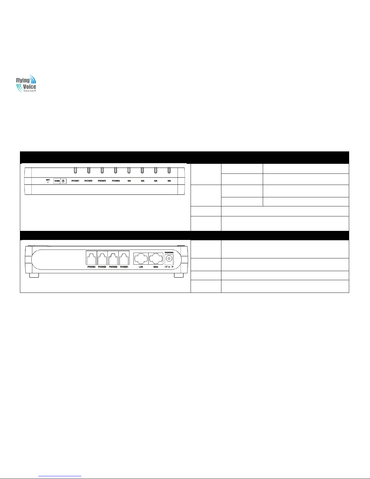
2.2 LED Indicators
2.2.1 G504 LED Indicators
Front Panel
LED
Status
Explanation
PHONE1/2/
3/4
Blinking(Green)
Not registered.
On (Green)
Registered
POWER
On(Red)
The router is powered on and running
normally.
Off
The router is powered off.
N/A
Not available
RST
Press itto restore factory settings above 5S
Rear Panel
Interface
Description
DC
12V/2A
Connector for a power adapter.
Phone1/2/3/
4
Connect to the phone.
WAN
Connector for accessing the Internet.
LAN
Connectors for local networked devices.
Copy Right 2014 All Rights Reserved by FLYINGVOICE TECHNOLOG LIMITED
V1.0
The page 8 of 62
Revision time: 2014-12-11 9:00
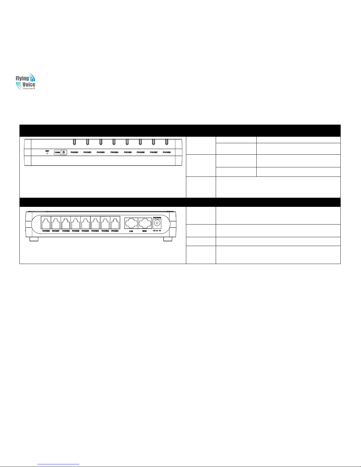
2.2.2 G508LED Indicators
Front Panel
LED
Status
Explanation
PHONE1/2/
3/4/5/6/7/8
Blinking(Green)
Not registered.
On (Green)
Registered
POWER
On(Red)
The router is powered on and running
normally.
Off
The router is powered off.
RST
Press itto restore factory settings above 5S
Rear Panel
Interface
Description
DC
12V/2A
Connector for a power adapter.
Phone1/2/3/
4/5/6/7/8
Connect to the phone.
WAN
Connector for accessing the Internet.
LAN
Connectors for local networked devices.

Copy Right 2014 All Rights Reserved by FLYINGVOICE TECHNOLOG LIMITED
V1.0
The page 9 of 62
Revision time: 2014-12-11 9:00
2.3 Hardware Installation
Before starting to configure the router, you have to connect your devices correctly.
Step 1.Connect Line port to land line jack with a RJ-11 cable.
Step 2.Connect the WAN port to a modem or switch or router or Internet with an Ethernet cable.
Step 3.Connect one port of 4 LAN ports to your computer with a RJ-45 cable. This device allows you to connect 4 PCs directly.
Step 4.Connect one end of the power cord to the power port of this device. Connect the other end to the wall outlet of electricity.
Step 5.Push the ON/OFF button to power on the router.
Step 6.Check the Power and WAN, LAN LEDs to assure network connections.
Warning: Please do not attempt to use other different power adapter or cut off power supply during configuration or updating the
VoIP home gateway. Using other power adapter may damage the device and will void the manufacturer warranty.
Warning:changes or modifications not expressly approved by the party responsible for compliance could void the user’s authority
to operate the equipment.
This equipment has been tested and found to comply with the limits for a Class B digital device, pursuant to Part 15 of the FCC
Rules. These limits are designed to provide reasonable protection against harmful interference in a residential installation. This
equipment generates, uses and can radiate radio frequency energy and, if not installed and used in accordance with the
instructions, may cause harmful interference to radio communications. However, there is no guarantee that interference will not
occur in a particular installation.
If this equipment does cause harmful interference to radio or television reception, which can be determined by turning the
equipment off and on, the user is encouraged to try to correct the interference by one or more of the following measures:
-- Reorient or relocate the receiving antenna.
-- Increase the separation between the equipment and receiver.
-- Connect the equipment into an outlet on a circuit different from that to which the receiver is connected.
-- Consult the dealer or an experienced radio/TV technician for help.

Copy Right 2014 All Rights Reserved by FLYINGVOICE TECHNOLOG LIMITED
V1.0
The page 10 of 62
Revision time: 2014-12-11 9:00
2.4 Voice Prompt
In any circumstance, pressing the following command to enter relevant function. The following table lists command, and description.
VVooiiccee MMeennuu SSeettttiinngg OOppttiioonns
s
OOppeerraattiioonn ccooddee
CCoonntteennttss
11
Step 1.Pick up phone and press “****” to start IVR
Step 2.Choose “1”, and G504/G508 report the current WAN port connection type
Step 3.Prompt "Please enter password”, user need to input password with end char # if user want to configuration
WAN port connection type.
The password in IVR is sa me as the one o f WEB login, user can use phone keypad to en ter password directly,
and the matching table is in Note 4.
22
Step 1.Pick up phone and press “****” to start IVR
Step 2.Choose “2”, and G504/G508 report current WAN Port IP Address
Step 3.Input the new WAN port IP address and with the end char #,
using “*” to replace “.”, user can input 192*168*20*168 to set the new IP address 192.168.20.168
press # key to indicate that you have finished
Step 4.Report “operation successful” if user operation properly.
Note: If you want to quit by the wayside, press “**”.
33
Step 1.Pick up phone and press “****” to start IVR
Step 2.Choose “3”, and G504/G508 report current WAN port subnet mask
Step 3.Input a new WAN port subnet mask and with the end char #
using “*” to replace “.”, user can input 255*255*255*0 to set the new WAN port subnet mask 255.255.255.0
press # key to indicate that you have finished
3) Report “operation successful” if user operation properly.
Note: If you want to quit by the wayside, press “**”.
44
Step 1.Pick up phone and press “****” to start IVR
Step 2.Choose “4”, and G504/G508 report current gateway
Step 3.Input the new gateway and with the end char #
using “*” to replace “.”, user can input 192*168*20*1 to set the new gateway 192.168.20.1
press # (pound) key to indicate that you have finished
3) Report “operation successful” if user operation properly.
Note: If you want to quit by the wayside, press “**”.

Copy Right 2014 All Rights Reserved by FLYINGVOICE TECHNOLOG LIMITED
V1.0
The page 11 of 62
Revision time: 2014-12-11 9:00
55
Step 1.Pick up phone and press “****” to start IVR
Step 2.Choose “5”, and G504/G508 report current DNS
Step 3.Input the new DNS and with the end char #
using “*” to replace “.”, user can input 192*168*20*1 to set the new gateway 192.168.20.1
press # (pound) key to indicate that you have finished
3) Report “operation successful” if user operation properly.
If you want to quit by the wayside, press “**”.
66
Step 1.Pick up phone and press “****” to start IVR
Step 2.Choose “6”, and G504/G508 report “Factory Reset”
Step 3.Prompt "Please enter password", the method of inputting password is the same as operation 1.
If you want to quit by the wayside, press “*”.
Step 4.Prompt “operation successful” if password is right and then G504/G508 will be factory setting.
Step 5.Press “7” reboot to make changes effective.
77
Step 1.Pick up phone and press “****” to start IVR
Step 2.Choose “7”, and G504/G508 report “Reboot”
Step 3.Prompt "Please enter password", the method of inputting password is same as operation 1.
Step 4.G504/G508 will reboot if password is right and operation is properly.
88
Step 1.Pick up phone and press “****” to start IVR
Step 2.Choose “8”, and G504/G508 report “WAN Port Login”
Step 3.Prompt "Please enter password", the method of inputting password is same as operation 1.
If you want to quit by the wayside, press “*”.
Step 4.Report “operation successful” if user operation properly.
Step 5.Prompt “1enable 2disable”,choose 1 or 2, and with confirm char #
Step 6.Report “operation successful” if user operation properly.
99
Step 1.Pick up phone and press “****” to start IVR
Step 2.Choose “9”, and G504/G508 report “ WEB Access Port”
Step 3.Prompt “Please enter password”, the method of inputting password is same as operation 1.
Step 4.Report “operation successful” if user operation properly.
Step 5.Report the current WEB Access Port
Step 6.Set the new WEB access port and with end char #
Step 7. Report “operation successful” if user operation properly.
00
Step 1.Pick up phone and press “****” to start IVR
Step 2.Choose “0”, and G504/G508 report current Firmware version

Copy Right 2014 All Rights Reserved by FLYINGVOICE TECHNOLOG LIMITED
V1.0
The page 12 of 62
Revision time: 2014-12-11 9:00
NNoottiiccee::
1. When using Voice Menu, press *(star) to return the main menu.
2. If any changes made in the IP assignment mode, please reboot the G504/G508 to take the setting into effect.
3. When enter IP address or subnet mask, use “*”(Star) to replace “.” (Dot).
4. For example, to enter the IP address 192.168.20.159 by keypad, press these keys: 192*168*20*159,use the #(pound) key to
indicate that you have finished entering the IP address.
5. #(pound) key to indicate that you have finish entering the IP address or subnet mask
6. When assigning IP address in Static IP mode, setting IP address, subnet mask and default gatewayis a must. If in DHCP mode,
please make sure that DHCP SERVER is available in your existing broadband connection to which WAN port of G504/G508 is
connected.
7. The default LAN port IP address of G504/G508 is 192.168.1.1 and do not set the WAN port IP address of G504/G508 in the same
network segment of LAN port of G504/G508, otherwise it may lead to the G504/G508 fail to work properly.
8. You can enter the password by phone keypad, the matching table between number and letters as follows:
To input: D, E, F, d, e, f -- press „3‟
To input: G, H, I, g, h, i -- press „4‟
To input: J, K, L, j, k, l -- press „5‟
To input: M, N, O, m, n, o -- press „6‟
To input: P, Q, R, S, p, q, r, s -- press „7‟
To input: T, U, V, t, u, v -- press „8‟
To input: W, X, Y, Z, w, x, y, z -- press „9‟
To input all other characters in the administrator password-----press „0‟,
E.g. password is „admin-admin‟, press „236460263‟

Copy Right 2014 All Rights Reserved by FLYINGVOICE TECHNOLOG LIMITED
V1.0
The page 13 of 62
Revision time: 2014-12-11 9:00
2.5 Configuring Basic Settings
2.6 Two-LevelManagement
This chapter explains how to setup a password for an administrator/root user and how to adjust basic/advanced settings for accessing
Internet successfully.
G504/G508 supports two-level management: administrator and user. For administratormode operation, please type “admin/admin” on
Username/Password and click Login buttonto configuration.While for user mode operation, please type “user/user” on Username/Password
and click Login button for full configuration.
2.7 AccessingWebPage
2.7.1 From LAN port
1. Make sure your PC have connected to the router‟s LAN port correctly
Notice:YoumayeithersimplysetupyourcomputertogetIPdynamicallyfromtherouterorsetuptheIPaddressofthecomputertobethesamesubnetas
thedefaultIPaddressofrouteris 192.168.1.1.Forthedetailed information,pleasereferto thelater section-Troubleshootingoftheguide.
2. Open a web browser on your PC and type http://192.168.1.1. The following window will be open to ask for username and password,and
you can choose language.
3. For administratormode operation, please type “admin/admin” on Username/Password and click Login to configuration.Yet, for root user
mode operation, please type “user/user” on Username/Password and click Login for full configuration.
Notice: If you fail to access to the web configuration, please go to “Tro uble
Shooting” for detecting and solving your problem.

Copy Right 2014 All Rights Reserved by FLYINGVOICE TECHNOLOG LIMITED
V1.0
The page 14 of 62
Revision time: 2014-12-11 9:00
4. The web page can be logged out after 5 minutes without any operation.
2.7.2 From WAN port
Make sure your PC can connect to the router‟s WAN port correctly.
Getting the IP addresses of WAN port using Voice prompt.
1. Open a web browser on your PC and type
hhttttpp::////tthhee IIPP aaddddrreessss ooff WWAANN ppoorrtt.
.The following window will be open to ask for username and
password.
2. For administratormode operation, please type
“
“
aaddmmiinn//aaddmmiin
n
”
”
on Username/Password and click Login to configuration.Yet, for root user mode
operation, please type “user/user” on Username/Password and click Login for full configuration.
Notice: If you fail to access to the web configuration, please go to “Trouble
Shooting” for detecting and solving your problem.
3. The web page can be logged out after 5 minuteswithout any operation.
4. User can use the two parameters in Web Access to control WAN web login or login port.
WAN Interface Login is to disable/enable user access to web via WAN port;
Web Login Port is to set login port.
Copy Right 2014 All Rights Reserved by FLYINGVOICE TECHNOLOG LIMITED
V1.0
The page 15 of 62
Revision time: 2014-12-11 9:00
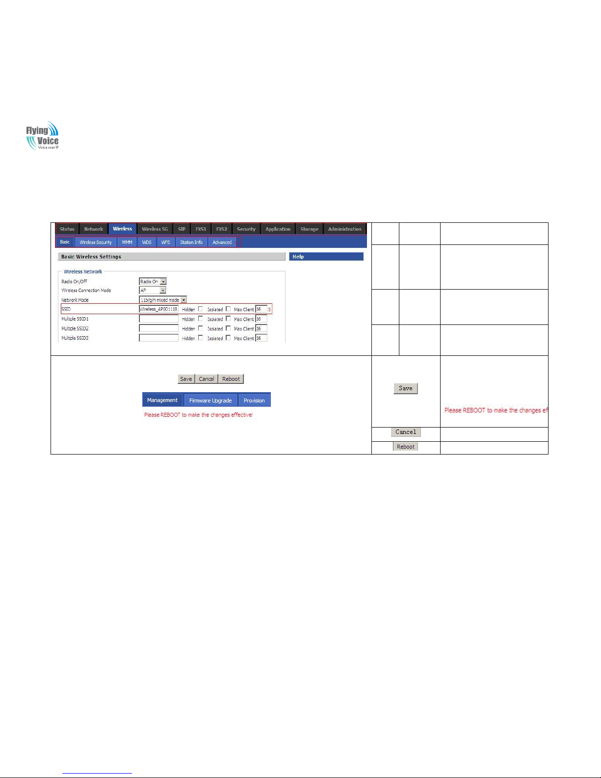
2.8 WEB Page
NO.
FieldNam
e
Description
1
Navigatio
n bar
Click navigation bar, many
sub-navigation bar will appear in
the place 2
2
Title
Click sub-navigation bar to
choose one configuration page
3
Paramete
r
To configuration the parameters
1.Every time making some
changes, user should press this
button to confirm the changes.
2.After pressing the button, the
red
will appear to notice rebooting.
To cancel the changes.
Press it to reboot the router
Copy Right 2014 All Rights Reserved by FLYINGVOICE TECHNOLOG LIMITED
V1.0
The page 16 of 62
Revision time: 2014-12-11 9:00
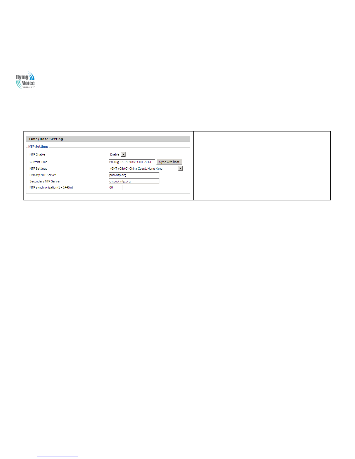
2.9 Setting up the Time Zone
Open Administration/Management webpage as shown left, please
select the Time Zone for the router installed and specify the NTP server
and set the update interval in NTP synchronization.
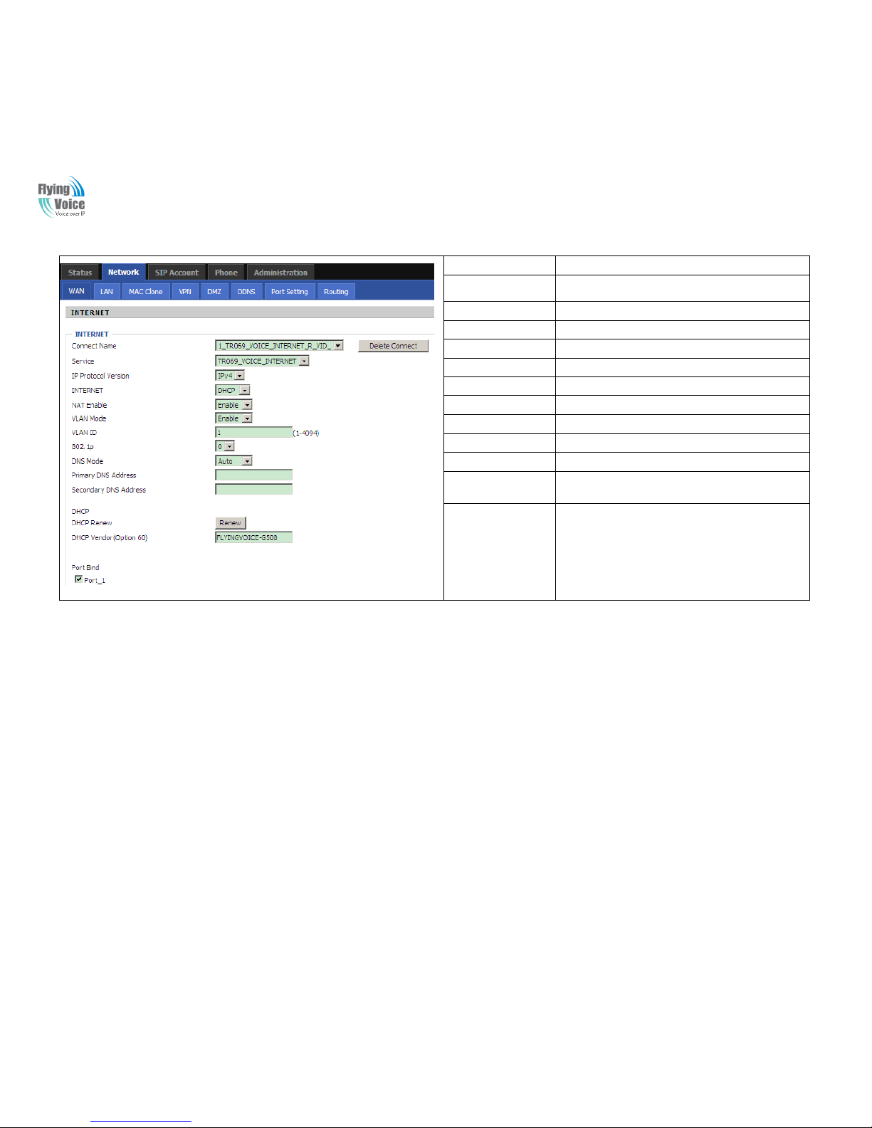
2.10 Setting up the Internet Connection
From WAN page, multi wan connection could be built or deteted. If you want to know more information about Internet Connection setting,
please refer to 3.2 section.
Copy Right 2014 All Rights Reserved by FLYINGVOICE TECHNOLOG LIMITED
V1.0
The page 17 of 62
Revision time: 2014-12-11 9:00
Field Name
Description
Connect Name
Use keywords to indicate WAN port service model
Service
Chose the service mode.
IP Protocol Version
Only IPv4 for G504/G508
INTERNET
Choose Internet connection mode.
NAT Enable
If or not enable NAT.
VLAN Mode
If or not enable VLAN Mode.
VLAN ID
Set the VLAN ID.
802.1p
Set the priority of VLAN, Options are 0~7.
DNS Mode
The default is Manual.
Primary DNS Address
The primary DNS of Internet port.
Secondary DNS
Address
The secondary DNS of Internet port.
Port Bind
Port bind is used for binding the service for different
LAN ports and SSIDs.
2.11 Register
2.11.1 Get the Accounts
G504 have 4 FXS ports, G508 have 8 FXS ports ,you can use them to make SIP call, and before registering, you should get the SIP account
from you administrator or provider.
2.11.2 Connections
Connect G504/G508 to the Internet properly.
Copy Right 2014 All Rights Reserved by FLYINGVOICE TECHNOLOG LIMITED
V1.0
The page 18 of 62
Revision time: 2014-12-11 9:00
2.11.3 Configuration SIP from Webpage
Step 1.Select a FXS port from the drop_down list, as the picture in the
left side.
Step 2.Fillthe SIP Server domain and SIP Server address (which get from
you administrator or provider) into Domain Name parameter, into SIP
Server
Step 3.Fill account which get from you administrator into Display Name
parameter, Phone Number parameter, and Account parameter.
Step 4.Fill password which get from you administrator into Password
parameter.
Step 5.Press button in the bottom of the webpage to save changes.
Note: if there is , please press
button to make changes effective.
Copy Right 2014 All Rights Reserved by FLYINGVOICE TECHNOLOG LIMITED
V1.0
The page 19 of 62
Revision time: 2014-12-11 9:00
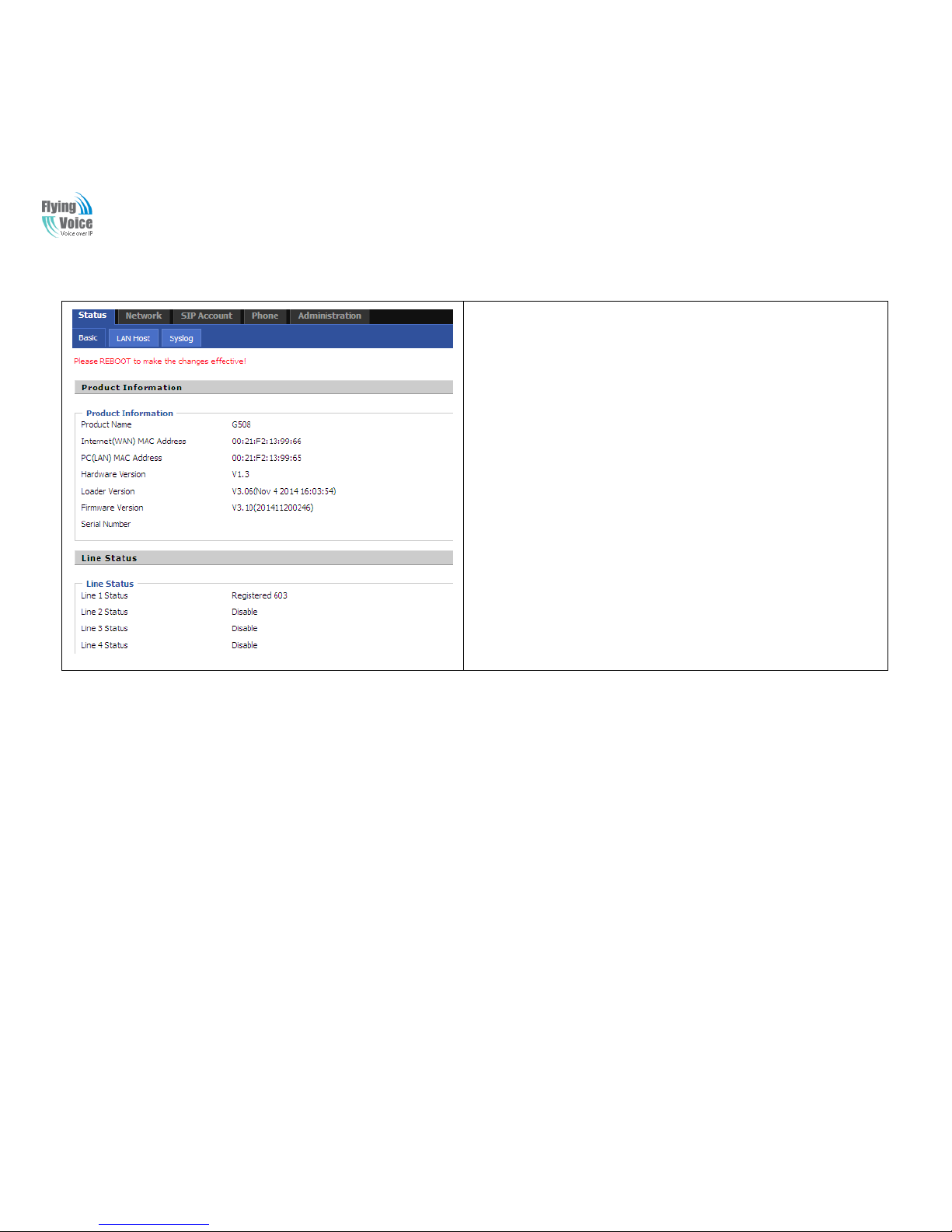
2.11.4 View the Register Status
To view the status, please open Status webpage and view the value of register status.
The value is registered like the following picture which means G504/G508 have
registered normally and you can make calls.

Copy Right 2014 All Rights Reserved by FLYINGVOICE TECHNOLOG LIMITED
V1.0
The page 20 of 62
Revision time: 2014-12-11 9:00
3 Web Configuration
This chapter will guide users to execute advanced(full) configuration through admin mode operation.
3.1 Status
This webpage shows the status information about product information,
Network and system.
Product information shows the basic information of the product, such as
product name, serial number, MAC address, hardware version and software
version
Network Status shows the information of Link Status, WAN Port Status, and
LAN Port Status.
This page also shows the current time and the running time of the product.
The picture in the left side is the G504’s Status webpage.

Copy Right 2014 All Rights Reserved by FLYINGVOICE TECHNOLOG LIMITED
V1.0
The page 21 of 62
Revision time: 2014-12-11 9:00
3.2 Network
You can configuration the WAN port, LAN port, DDNS, DMZ, MAC Clone, Port Forward and so on in these bars.
3.2.1 WAN
This page allows you to set WAN configuration with different modes. Use the Connection Type drop down list to choose one WAN mode and
then the corresponding page will be displayed.
1. Static IP
You will receive a fixed public IP address or a public subnet, namely multiple public IP addresses from your DSL or Cable ISP service
providers. In most cases, a Cable service provider will offer a fixed public IP, while a DSL service provider will offer a public subnet. If you
have a public subnet, you could assign an IP address to the WAN interface.
Field Name
Description
IP Address
The IP address of Internet port
Subnet Mask
The subnet mask of Internet port.
Default Gateway
The default gateway of Internet port.
DNS Mode
In Static mode, user need set the DNS
manually.
Primary DNS
Address
The primary DNS of Internet port.
Secondary DNS
Address
The secondary DNS of Internet port.

Copy Right 2014 All Rights Reserved by FLYINGVOICE TECHNOLOG LIMITED
V1.0
The page 22 of 62
Revision time: 2014-12-11 9:00
2. DHCP
It is not necessary for you to type any IP address manually. Simply choose this type and the system will obtain the IP address automatically
from DHCP server.
Field Name
Description
DNS Mode
The Default is Manual
Primary DNS
Address
The primary DNS of Internet port.
Secondary DNS
Address
The secondary DNS of Internet port.
DHCP Renew
Refresh DHCP IP
DHCP
Vendor(Option60)
Specify DHCP Vendor field
Display the vendor and product name

Copy Right 2014 All Rights Reserved by FLYINGVOICE TECHNOLOG LIMITED
V1.0
The page 23 of 62
Revision time: 2014-12-11 9:00
3. PPPoE
PPPoE stands for Point-to-Point Protocol over Ethernet. It relies on two widely accepted standards: PPP and Ethernet. It connects users
through an Ethernet to the Internet with a common broadband medium, such as a single DSL line, wireless device or cable modem. All the
users over the Ethernet can share a common connection.
PPPoE is used for most of DSL modem users. All local users can share one PPPoE connection for accessing the Internet. Your service
provider will provide you information about user name, password, and authentication mode.
Field Name
Description
PPPoE Account
Assign a valid user name provided by the ISP
PPPoE
Password
Assign a valid password provided by the ISP
Confirm
Password
Enter your PPPoE password again
Operation Mode
Select the mode of operation, options are Keep Alive,
On Demand and Manual:
1.When the mode is Keep Alive, user need to set the
'keep alive redial period' values range from 0 to
3600s, the default setting is 5s;
2. When the mode is On Demand, user need to set the
'on demand idle time' value in the range of 0-60
minutes, the default setting is 5 minutes;
3.When the mode is Manual, no need to do other
settings.
Keep Alive
Redial Period
Set the interval to send Keep Alive

Copy Right 2014 All Rights Reserved by FLYINGVOICE TECHNOLOG LIMITED
V1.0
The page 24 of 62
Revision time: 2014-12-11 9:00
4. Bridge Mode
Bridge Mode under Multi WAN is different with traditional bridge setting. Bridge mode has no ip address and only work as a bridge between
WAN port and LAN port. So Route Connection has to be build to give ip address to local service on device.
Under is example of bridge mode:
1_TR069_VOICE_INTERNET_R_VID_ is router connection for local service.
2_Other_B_VID_ is bridge connection for host of LAN port.
If bridge setting is complex, please refer to 5.4 section for fast setting of bridge mode.
Field Name
Description
Bridge
Type
IP Bridge
Allow all ethernet packets pass. PC could connect
to upper network directly.
PPPoE
Bridge
Only Allow PPPoE packets pass. PC need PPPoE
dial-up software.
Hardware IP
Bridge
Packets pass through hardware switch with wired
speed. Do not support wireless port bind.
DHCP
Service
Type
Pass Through
DHCP packets can be forwarded between WAN
and LAN, DHCP server in gateway will not
allocate IP to hosts of LAN port.
DHCP
Snooping
When gateway forwards DHCP packets form
LAN to WAN it will add option82 to DHCP
packet, and it will remove option82 when forward
DHCP packet form WAN to LAN. Local DHCP
service will not allocate ip to hosts of LAN port.
Local Service
Gateway will not forward DHCP packets between
Lan and Wan, it also block DHCP packet from
WAN port. HostsofLAN port can get ip from
DHCP server run in gateway.
VLAN
Mode
Disable
The WAN interface is untagged. LAN is
untagged.
Enable
The WAN interface is tagged. LAN is untagged.
Trunk
Only valid in bridge mode. All ports, include
WAN and LAN, belong to this VLAN Id and all
ports are tagged in this VLAN id. Tagged packets
could pass through WAN and LAN.
VVLLAANN IID
D
Set the VLAN ID.
802.1p
Set the priority of VLAN, Options are 0~7.

Copy Right 2014 All Rights Reserved by FLYINGVOICE TECHNOLOG LIMITED
V1.0
The page 25 of 62
Revision time: 2014-12-11 9:00
5. Connect Name and Service
Connect Name Table is as below:
Content
Define
Comment
No
1~99
WAN Connection id
Service
TR069
The connection only support management application, like TR069, WEB, SNMP
and Provision
INTERNET
The connection only support internet service
TR069_INTERNET
The connection support management and internet application
VOICE
The connection only support voice application, like sip and rtp
TR069_VOICE
The connection support both management and voice application
VOICE_INTERNET
The connection support voice and internet application
TR069_VOICE_INTERNET
The connection support management, voice and internet application
Other
The connection support STB
NAT Mode
B
Bridge
R
Router
VLAN ID
VID
VLAN ID
For example:
1. 1_TR069_R_VID_2 (First Interface, Service is TR069, NAT Mode, VLAN ID is 2)
2. 2_INTERNET_B_VID_(Second Interface, Service is INTERNET, Bridge Mode, VLAN is disabled)

Copy Right 2014 All Rights Reserved by FLYINGVOICE TECHNOLOG LIMITED
V1.0
The page 26 of 62
Revision time: 2014-12-11 9:00
3.2.2 LAN
1. LAN Port:
The most generic function of router is NAT. What NAT does is to translate the packets from public IP address to local IP address to forward
the right packets to the right host and vice versa.
Field Name
Description
IP Address
Enter the IP address of the router on the local area network, all the IP
addresses of the computers which are in the router’s LAN must be in the
same network segment with this address, and the default gateway of the
computers must be this IP address. (The default is 192.168.1.1)
Local Subnet
Mask
Enter the subnet mask to determine the size of the network (default is
255.255.255.0/24)
Local DHCP
Server
If or not enable Local DHCP Server
DHCP Start
Address
Enter a valid IP address as a starting IP address of the DHCP server, and if
the router’s LAN IP address is 192.168.1.1, starting IP address can be
192.168.1.2 or greater, but should be less than the ending IP address.
DHCP End
Address
Enter a valid IP address as an endIP address of the DHCP server.
DNS Mode
Select DNS mode, options are Auto and Manual:
1.When DNS mode isAuto, the device under LAN port will automatically
obtains the preferred DNS and alternate DNS.
2. When DNS mode is Manual, the user should manually configure the
preferred DNS and alternate DNS
Primary
DNS
Enter the preferred DNS address.
Secondary
DNS
Enter the secondary DNS address.
Client Lease
Time
This option defines how long the address will be assigned to the computer
within the network. In that period, the server does not assign the IP addressto
the other computer.
DNS Proxy
Enable or disable; If enabled, the device will forward the DNS request of
LAN-side network to the WAN side network
2. DHCP Server:
Router has a built-in DHCP server that assigns private IP address to each local host.
DHCP stands for Dynamic Host Configuration Protocol. The router by factory default acts a DHCP server for your network so it automatically
dispatch related IP settings to any local userconfigured as a DHCP client. It is highly recommended that you leave the router enabled as a
DHCP server if you do not have a DHCP server for your network.

Copy Right 2014 All Rights Reserved by FLYINGVOICE TECHNOLOG LIMITED
V1.0
The page 27 of 62
Revision time: 2014-12-11 9:00
Field Name
Description
Local DHCP
Server
If or not enable DHCP server.
DHCP Start
Address
Enter a value of the IP address pool for the DHCP server to start with
when issuing IP addresses. If the LAN Interface IP
DHCP
EndAddress
Enter a value of the IP address pool for the DHCP server to end with
when issuing IP addresses.
DNS Mode
You should set “manual” in the “DNS Mode” if you set “DNS” by
yourself. And then fill the DNS in the two following texts. Generally
speaking, you can set “Auto” in the “DNS Mode” a nd the device will
get “DNS” from DHCP Server automatically.
Primary DNS
You must specify a DNS server IP address here because yourISP should
provide you with usually more than one DNS Server. If your ISP does
not provide it, the router will automatically apply default DNS Server IP
address: 202.96.134.33 to this field.
Secondary
DNS
You must specify a DNS server IP address here because yourISP should
provide you with usually more than one DNS Server. If your ISP does
not provide it, the router will automatically apply default DNS Server IP
address: 202.96.128.86to this field.
If both the Primary IP and Secondary IP Address fields are left empty,
the router will assign its own IP address to local users as a DNS proxy
server and maintain a DNS cache.
Client Lease
Time
It allows you to set the leased time for the specified PC.
3.2.3 MAC Clone
Some ISPs will require you to register your MAC address. If you do not wish to re-register your MAC address, you can have the router clone
the MAC address that is registered with your ISP.To use the Clone Address button, the computer viewing the Web-base utility screen will
have the MAC address automatically entered in the Clone WAN MAC field.

Copy Right 2014 All Rights Reserved by FLYINGVOICE TECHNOLOG LIMITED
V1.0
The page 28 of 62
Revision time: 2014-12-11 9:00
Enabling MAC address cloning
1. Press the button gets PC's MAC address
2. Press the button to save your changes if users don't want to
use MAC clone, press the button to cancel the changes
3. Press the button to make the changes effective.
3.2.4 VPN
A VPN is a kind of technology which establish a private network based on the public network. VPN network connection between any two
nodes does not require the end to end physical connection as the traditional private network; it is structuredon the network platform provided
by the public network services, the user dhome gateway are transmitted in the logical link. Through VPN technology, users can establish
connection between any two devices which are connected to public network and transmit dhome gateway.
Field Name
Description
VPN Enable
If or not enable VPN.If enable, you can
select PPTP and L2TP mode VPN.
Initial Service
IP
Fill in the VPN server IP address
User Name
Fill in the authenticationusername
Password
Fill in the authentication password
3.2.5 DMZ
Field Name
Description
DMZ Enable
If or not enable DMZ.
DMZ Host IP Address
Enter the private IP address of the DMZ host

Copy Right 2014 All Rights Reserved by FLYINGVOICE TECHNOLOG LIMITED
V1.0
The page 29 of 62
Revision time: 2014-12-11 9:00
3.2.6 DDNS
Field Name
Description
Dynamic DNS
Provider
DDNS is enabled and select a DDNS service provider
Account
Enter the DDNS service account
Password
Enter the DDNS service account password
DDNS
Enter the DDNS domain name or IP address
Status
See if DDNS is successfully upgraded
3.2.7 Port Forward
Field Name
Description
WANPort Speed
Nego
Auto-negotiation, options are Auto, 1000M full, 1000M
half-duplex,100M half and full, 10M half and full, select
port speed negotiation supported by methods.
LAN1~LAN4Port
Speed Nego
Auto-negotiation, options are Auto, 1000M full, 1000M
half, 100M half and full,10M half and 10M full, select
port speed negotiation methods.

Copy Right 2014 All Rights Reserved by FLYINGVOICE TECHNOLOG LIMITED
V1.0
The page 30 of 62
Revision time: 2014-12-11 9:00
3.2.8 Routing
Field Name
Description
Destination
Destination address
Host/Net
Both Host and Net selection
Gateway
Gateway IP address
Interface
LAN/WAN/Custom three options, and
add the corresponding address
Comment
Comment

Copy Right 2014 All Rights Reserved by FLYINGVOICE TECHNOLOG LIMITED
V1.0
The page 31 of 62
Revision time: 2014-12-11 9:00
3.3 SIP Account
3.3.1 Account
You can set each FXS’s display name,phone number,account and password in this
page,the corresponding FXS will be enable after checked enable .then save your settings.
Click “Other settings” go to the “FXS Settings” web page.

Copy Right 2014 All Rights Reserved by FLYINGVOICE TECHNOLOG LIMITED
V1.0
The page 32 of 62
Revision time: 2014-12-11 9:00
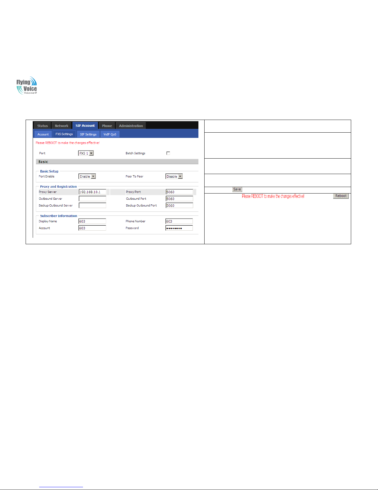
3.3.2 FXS Setting
1. Basic
Set the basic information provided by your VOIP Service Provider, such as Phone Number, Account, password, SIP Proxy and so on.
Field Name
Description
Port
Setlect a FXS port
Batch Setting
Check this item,the left port will show as below:
Select the start Port and the End Port,these ports
will be set to the same setting.
PortEnable
If or not enable the selected line port.
Peer To Peer
If or not enable PEER to PEER.
If enable, SIP-1 will not send register request to
SIP server; but in Status/ SIP Account Status
webpage, Status is Registered; lines 1 can dial out,
but the external line number cannot dialed line1.
Proxy Server
The IP address or the domain of SIP Server
Outbound Server
The IP address or the domain of Outbound Server
Backup Outbound Server
The IP address or the domain of Backup Outbound
Server
Proxy port
SIP Service port, default is 5060
Outbound Port
Outbound Proxy’s Service port, default is 5060
Backup Outbound Port
Backup O utbound Proxy’s Service port, default is
5060
Display Name
The number will be displayedon LCD
Phone Number
Enter telephone number provided by SIP Proxy
Account
Enter SIP account provided by SIP Proxy
Password
Enter SIP password provided by SIP Proxy

Copy Right 2014 All Rights Reserved by FLYINGVOICE TECHNOLOG LIMITED
V1.0
The page 33 of 62
Revision time: 2014-12-11 9:00
2. Audio Configuration
Field Name
Description
Audio Codec Type1
Choose the audio codec type from G.711U, G.711A,
G.722, G.729, G.723
Audio Codec Type2
Choose the audio codec type from G.711U, G.711A,
G.722, G.729, G.723
Audio Codec Type3
Choose the audio codec type from G.711U, G.711A,
G.722, G.729, G.723
Audio Codec Type4
Choose the audio codec type from G.711U, G.711A,
G.722, G.729, G.723
Audio Codec Type5
Choose the audio codec type from G.711U, G.711A,
G.722, G.729, G.723
G.723 Coding Speed
Choose the speed of G.723 from 5.3kbps and
6.3kbps
Packet Cycle
The RTP packet cycle time, default is 20ms
Silence Supp
If or not enable silence
Echo Cancel
If or not enable echo cancel, default is enable
Auto Gain Control
If or not enable auto gain.
T.38 Enable
If or not enable T.38
T.38 Redundancy
If or not enable T.38 Redundancy
T.38CNG Detect
Enable
If or not enable T.38 CNG Detect
gmd attribute
Enable
If or not enable gmd attribute.

Copy Right 2014 All Rights Reserved by FLYINGVOICE TECHNOLOG LIMITED
V1.0
The page 34 of 62
Revision time: 2014-12-11 9:00
3. Supplementary Service Subscription
Field Name
Description
Call Waiting
If or not enable Call Waiting
Hot Line
Fill in the hotline number.
Pickup handset or press handsfree/headset
button, the device will dial out the hotline
number automatically.
MWI Enable
If or not enable MWI (message waiting
indicate). If the user needs to user voice mail,
please enable this feature.
MWI Subscribe Enable
If or not enable MWI Subscribe
Voice Mailbox Numbers
Fill in the voice mailbox phone number,
Asterisk platform, for example, its default
voice mail is *97
VMWI Serv
If or not enable VMWI service.
DND
If or not enable DND (do not disturb).
If enable, any phone callcannot arrive at the
device;default is disable.
Speed Dial
Enter the speed dial phone numbers.
Dial *74 to active speed dial function.
Then press the speed dial numbers, for
example, press 2, phone will dial
075526099365 directly.

Copy Right 2014 All Rights Reserved by FLYINGVOICE TECHNOLOG LIMITED
V1.0
The page 35 of 62
Revision time: 2014-12-11 9:00
4. Advanced
Field Name
Description
Domain Name Type
If or not use domain name in the SIP URI.
Carry Port Information
If or not carry port information in the SIP URI.
Signal Port
The local port of SIP protocol, default is 5060.
DTMF Type
Choose the DTMF type from Inbound,
RFC2833 and SIP INFO.
RFC2833 Payload(>=96)
User can use the default setting.
Register Refresh Interval
The interval between two normal Register
messages. You can use the default setting.
RTP Port
Set the port to send RTP.
The device will select one idle port for RTP if
you set “0”; otherwise use the value which user
sets.
Cancel Message Enable
When you set enable, an unregistered message
will be sent before registration, while you set
disable, unregistered message will not be sent
before registration. You should set the option
for different Proxy.
Session Refresh Time(sec)
Time interval between two sessions, you can
use the default settings.
Refresher
Choose refresher from UAC and UAS.
Prack Enable
If or not enable prack.
SIP OPTIONS Enable
When you set enable, the device will send
SIP-OPTION to the server, instead of sending
periodic Hello message. The sending interval is
Keep-alive interval.
Primary SER Detect
Interval
Test interval of the primary server, the default
value is 0, it represents disable.
Max Detect Fail Count
Interval of detection of the primary server fail;
the default value is 3, it means that if detect 3
times fail; the device will no longer detect the
primary server.
Keep-alive Interval(10-60s)
The interval that the device will send an empty
packet to proxy.
Anonymous Call
If or not enable anonymous call.

Copy Right 2014 All Rights Reserved by FLYINGVOICE TECHNOLOG LIMITED
V1.0
The page 36 of 62
Revision time: 2014-12-11 9:00
Anonymous Call Block
If or not enable anonymous call block.
Proxy DNS Type
Set the DNS server type, choose from A type
and DNS SRV.
Use OB Proxy In Dialog
If or not use OB Proxy In Dialog.
Reg Subscribe Enable
If enable, subscribing will be sent after
registration message, if not enable, do not send
subscription.
Dial Prefix
The number will be added before your
telephone number when making calls.
User Type
Choose the User Type from IP and Phone.
Hold Method
Choose the Hold Method from ReINVITE and
INFO.
Request-URI User Check
If or not enable the user request URI check.
Only Recv request from
server
If or not enable the only receive request from
server.
Server Address
The IP address of SIP server.
SIP Received Detection
If or not enable SIP Received Detection, if
enable, use it to confirm the public network
address of the device.

Copy Right 2014 All Rights Reserved by FLYINGVOICE TECHNOLOG LIMITED
V1.0
The page 37 of 62
Revision time: 2014-12-11 9:00
3.3.3 SIP Settings
Field Name
Description
SIP T1
The minimum scale of retransmission time
Max Forward
Sip packets Max Forward message header
fields used to limit the request which jump
in his destination . To limit the number that
forwarding a request to the proxy or
gateway of next node intermediate.
SIP Reg User Agent Name
The agent name of SIP registered user
Max Auth
The maximum number of retransmissions
Mark All AVT Packets
Voice packet marking,to enable this item
will see the mark on the voice message
when the call environment changed (such as
press a key during the call)
RFC 2543 Call Hold
Enable,the Connection Information field
displays the address is 0.0.0.0 in the invite
message of Hold.
Disable,the Connection Information field
displays the device ip address in the invite
message of Hold.
SRTP
Whether to enable the call packet encryption
function
SRTP Prefer Encryption
The preferred encryption type of calling
packet (the Message body of INVITE
Message)
Service Type
Choose the server type
NAT Traversal
1.If or not enable NAT Traversal
2. G504/G508 supports STUN Traversal; If
you want to traverse NAT/Firewall, select
the STUN.
STUN Server Address
Add the correct STUN service provider IP
address.
NAT Refresh Interval
Set NAT Refresh Interval, default is 60s.
STUN Server Port
Set STUN Server Port, default is 5060.

Copy Right 2014 All Rights Reserved by FLYINGVOICE TECHNOLOG LIMITED
V1.0
The page 38 of 62
Revision time: 2014-12-11 9:00
3.3.4 VoIP Qos
Field Name
Description
SIP /RTP QoS
The default value is 0,you can set a range of
values is 0~63

Copy Right 2014 All Rights Reserved by FLYINGVOICE TECHNOLOG LIMITED
V1.0
The page 39 of 62
Revision time: 2014-12-11 9:00
3.4 Phone
3.4.1 Preferences
11.. VVoolluummee SSeettttiinnggss
Field Name
Description
Handset Input Gain
Adjust the handset input gain from 0 to 7.
Handset Volume
Adjust the output gain from 0 to 7.
22.. RReeggiioonnaall
Field Name
Description
Tone Type
Choose tone type form China, US, Hong Kong
and so on.
Dial Tone
Dial Tone
Busy Tone
Busy Tone
Off Hook Warning Tone
Off Hook warning tone
Ring Back Tone
Ring back tone
Call Waiting Tone
Call waiting tone
Min Jitter Delay
The M in va lue of home ga teway’s jitter delay,
home gateway is an adaptive jitter mechanism.
Max Jitter Delay
The Max value o f home gateway’s jitter de lay,
home gateway is an adaptive jitter mechanism.
Ringing Time
How long G504/G508 will ring when there is
an incoming call.
Ring Waveform
Select regional ring waveform, options are
Sinusoid and Trapezoid, the default Sinusoid.
Ring Voltage
Set ringing voltage, the default value is 70
Ring Frequency
Set ring frequency, the default value is 25
VMWI Ring Splash
Len(sec)
Set the VMWI ring splash length, default is
0.5s.

Copy Right 2014 All Rights Reserved by FLYINGVOICE TECHNOLOG LIMITED
V1.0
The page 40 of 62
Revision time: 2014-12-11 9:00
Flash Time Max(sec)
Set the Max value of the device’s flash time, the
default value is 0.9
Flash Time Min(sec)
Set the Min value of the device’s flash time, the
default value is 0.1
33.. FFeeaattuurreess aanndd CCaallll FFoorrwwaarrdd
Field Name
Description
Features
All Forward
If or not enable forward all calls
Busy Forward
If or not enable busy forward.
No Answer
Forward
If or not enable no answer forward.
Call
Forward
All Forward
Set the target phone number for all forward.
The device will forward all calls to the phone
number immediately when there is an
incoming call.
Busy Forward
The phone number which the calls will be
forwarded to when line is busy.
No Answer
Forward
The phone number which the call will be
forwarded to when there's no answer.
No Answer
Timeout
The seconds to delay forwarding calls, if
there is no answer at your phone.
Feature
Code
Hold key code
Call hold signatures, default is *77.
Conference key
code
Signature of the tripartite session, default is
*88.
Transfer key
code
Call forwarding signatures ,default is *98.
IVR key code
Signatures of the voice menu, default is ****.
R key enable
If or not enable R key way call features.
R key cancel
code
Set the R key cancel code, option are ranged
from R1 to R9, default value is R1.
R key hold code
Set the R key hold code, options are ranged
from R1 to R9, default value is R2.
R key transfer
code
Set the R key transfer code, options are
ranged from R1 to R9, default value is R4.

Copy Right 2014 All Rights Reserved by FLYINGVOICE TECHNOLOG LIMITED
V1.0
The page 41 of 62
Revision time: 2014-12-11 9:00
R key conference
code
Set the R key conference code, options are
ranged from R1 to R9, default value is R3.
Speed Dial Code
Speed dial code, default is *74.
44.. MMiisscceellllaanneeoouuss
Field Name
Description
Codec Loop Current
Set off-hook loop current, default is 26
Impedance Maching
Set impedance matching, default is US
PBX,Korea,Taiwan(600).
CID service
If or not enable displaying caller ID; If enable, caller
ID is displayed when there is an incoming call or it
won’t be displayed. Default is enable.
CWCID Service
If or not enable CWCID. If enable, the device will
display the waiting call’s caller ID, or it won’t
display. Default is disable.
Dial Time Out
How long G504/G508 will sound dial out tone when
G504/G508 dials a number.
Call Immediately Key
Choose call immediately key form * or #.
ICMP Ping
If or not enable ICMP Ping.
If enable this option, home gateway will ping the SIP
Server every interval time, otherwise, It will send
“hello” empty packet to the SIP Server.
Escaped char enable
Open special character translation function; if
enable, when you press the # key, it will be translated
to 23%, when disable, it is just #

Copy Right 2014 All Rights Reserved by FLYINGVOICE TECHNOLOG LIMITED
V1.0
The page 42 of 62
Revision time: 2014-12-11 9:00
3.4.2 Dial Plan
11.. PPaarraammeetteerrss aanndd SSeettttiinnggss
Field Name
Description
Dial Plan
If or not enable dial plan.
Line
Set the line.
Digit Map
Fill in the sequence used to match input number
The syntactic, please refer to the following Dial Plan
Syntactic
Action
Choose the dial plan mode from Deny and Dial Out.
Deny means G504/G508 will reject the matched number,
while Dial Out means G504/G508 will dial out the matched
number.
Move Up
Press it to move up.
Move Down
Press it to move down.

Copy Right 2014 All Rights Reserved by FLYINGVOICE TECHNOLOG LIMITED
V1.0
The page 43 of 62
Revision time: 2014-12-11 9:00
22.. AAddddiinngg oonnee ddiiaall ppllaann::
Step 1. Enable Dial Plan
Step 2. Click Add button, and the configuration table
Step 3. Fill in the value of parameters.
Step 4.Press OK button to end configuration.
Step 5. Press Save button to save changes
33.. DDiiaall PPllaann SSyynnttaaccttiicc
No.
String
Description
1
0 1 2 3 4 5 6 7 8 9 * #
Legal characters
2
x
Lowercase letter x stands for one legal character
3
[sequence]
To match one character form sequence.
For example:
1. [0-9]: match one digit form 0 to 9
2. [23-5*]: match one character from 2 or 3 or 4 or 5 or *
4
x.
Match to , , , …...
For example:
“01.”:can match ”0”, “01”, “011”, ”0111”, …….., ”01111…”
5
<dialed:substituted>
Replace dialed with substituted.
For example:
<8:1650>123456: input is “85551212”, output is“16505551212”
6
x,y
Make outside dial tone after dialing “x”, stop until dialing character “y”
For example:
“9,1xxxxxxxxxx”:the device reports dial tone after inputting “9”, stops
tone until inputting “1”
“9,8,010x”: make outside dial tone after inputting “9”, stop tone until
inputting “0”
7
T
Set the delayed time.
For example:
“<9:111>T2”: The de vice will dial o ut t he matched number “111” after 2
seconds.

Copy Right 2014 All Rights Reserved by FLYINGVOICE TECHNOLOG LIMITED
V1.0
The page 44 of 62
Revision time: 2014-12-11 9:00
3.4.3 Phonebook
In this page, user can upload or download blacklist file, and can add or delete or edit blacklist one by one.
Click to select the phonebook file and click
to upload it to G504/G508; Click to save the
phonebook file to your local computer.
Click to select the blacklist file and click to
upload it to G504/G508; Click to save the
blacklist file to your local computer.
Select one contact and click edit to change the information, click
delete to delete the contact, click Move to blacklist to move the
contact to blacklist.
Click Add to add one phonebook, enter the name and phone
number, click OK to confirm and click cancel to cancel.

Copy Right 2014 All Rights Reserved by FLYINGVOICE TECHNOLOG LIMITED
V1.0
The page 45 of 62
Revision time: 2014-12-11 9:00
Select one contact and click edit to change the information, click
delete to delete the contact, click Move to phonebook to move the
contact to phonebook.
Click Add to add one blacklist, enter the name and phone number,
click OK to confirm and click cancel to cancel.
3.4.4 Call Log
To view the call log information such as redial list (incoming call), answered call and missed cal
Redial List

Copy Right 2014 All Rights Reserved by FLYINGVOICE TECHNOLOG LIMITED
V1.0
The page 46 of 62
Revision time: 2014-12-11 9:00
Answered Calls
Missed Call

Copy Right 2014 All Rights Reserved by FLYINGVOICE TECHNOLOG LIMITED
V1.0
The page 47 of 62
Revision time: 2014-12-11 9:00
3.5 Administration
Use can manage the device in these webpage; you can configure the Time/Date, password, web access, system log and associated
configuration TR069
3.5.1 Management
You can configure the value of Time/Date, password, web access, and system log and so on.
11.. SSaavvee ccoonnffiigg ffiillee
Field Name
Description
Config file
upload and
download
Upload: click on browse, select file in the local, press the upload button to begin
uploading files
Download: click to download, and then select contains the path to download the
configuration file
22.. AAddmmiinniissttrraattoorr sseettttiinnggss
Field Name
Description
User type
Choose the user type from admin user and normal user and
basic user.
New User Name
You can modify the user name, set up a new user name
New Password
Input the new password
Confirm Password
Input the new password again
Language
Select the language for the web, the device support Chinese,
English, and Spanish and so on.
Remote Web Login
If or not enable remote Web login
Web Port
Set the port value which is used to login from Internet port
and PC port, default is 80.
Web Idle timeout
Set the Web Idle timeout time. The webpage can be logged
out after Web Idle Timeout without any operation.
Allowed Remote
IP(IP1,IP2,...)
Set the IP which can login the device remotely.
Remote Telnet
If or not enable remote telnet login
Telnet Port
Set the port value which is used to telnet the device.

Copy Right 2014 All Rights Reserved by FLYINGVOICE TECHNOLOG LIMITED
V1.0
The page 48 of 62
Revision time: 2014-12-11 9:00
33.. TTiimmee//DDaattee sseettttiinnggss
Field Name
Description
NTP Enable
If or not enable NTP
Current Time
Display current time
NTP Settings
Setting the Time Zone
Primary NTP Server
Primary NTP server's IP address or domain name
Secondary NTP Server
Options for NTP server's IP address or domain name
NTP synchronization
NTPsynchronizationcycle, cycle timecan be1 to 1440
minutesin anyone, the default setting is 60 minutes
44.. DDaayylliigghhtt SSaavviinngg TTiimmee
Daylight Saving Time (or summer time as it is called in many countries) is a way of getting more light out of the day by advancing clocks by
some hour during the summer. During Daylight Saving Time, the sun appears to rise one hour later in the morning, when people are usually
asleep anyway, and sets one hour later in the evening, seeming to stretch the day longer.
Set the summer time steps:
Step 1.Open Administration/Management webpage.
Step 2.Enable parameter Daylight Saving Time in Time/Date.
Step 3.Set offset: “-60” means advancing 60min, “60” means delaying 60min.
Step 4.Set starting Month/Week/Day/Hour in Start Month/Start Day of Week Last in
Month/Start Day of Week/Start Hour of Day, analogously set stopping
Month/Week/Day/Hour in Stop Month/Stop Day of Week Last in Month/Stop Day
of Week/Stop Hour of Day.
Step 5.Press Saving button to save and press reboot button to active changes.
55.. SSyysstteemm LLoogg SSeettttiinngg
User can view system log in local or in remote.
In local:
Step 1.Open Administration/Management page, System Log Setting column.
Step 2.Choose log level from INFO and Debug, in INFO level, G504/G508 records INFO log, and in Debug level, G504/G508 records all
debug information.
Step 3.Press Save button to save and then press Reboot button to make changes effective.
In remote:
Step 1.Open Administration/Management page, System Log Setting column.
Step 2.Fill system server IP Address or domain name into Syslog Server.
Step 3.Choose log level from INFO and Debug, in INFO level, G504/G508 records INFO log, and in Debug level, G504/G508 records all

Copy Right 2014 All Rights Reserved by FLYINGVOICE TECHNOLOG LIMITED
V1.0
The page 49 of 62
Revision time: 2014-12-11 9:00
debug information.
Step 4.Press Save button to save and then press Reboot button to make changes effective.
66.. FFaaccttoorryy DDeeffaauullttss SSeettttiinngg
If enable this function ,the device will not be restore factory settings
77.. PPaacckkeett TTrraaccee
Users can use the packet trace feature intercepts the packets that were sent. Click
the Start button, start dhome gateway tracking and keep refreshing the page until
the message trace shows to stop, click the Save button to save captured packets.
88.. FFaaccttoorryy DDeeffaauullttss
Click Factory Default to restore the residential gateway to factory settings.
Field Name
Description
Syslog Enable
If or not enable syslog function
Syslog Level
Select the system log, there is INFO and Debug two
grades, the Debug INFO can provide more information.
Remote Syslog Enable
If or not enable remote syslog function.
Remote Syslog server
Add a remote server IP address.

Copy Right 2014 All Rights Reserved by FLYINGVOICE TECHNOLOG LIMITED
V1.0
The page 50 of 62
Revision time: 2014-12-11 9:00
3.5.2 Firmware Upgrade
Function is to upgrade firmware in local.
Step 1.Open Administration/Firmware Upgrade webpage
Step 2.Press to browse a firmware file
Step 3.Press to start upgrading
Step 4.When upgrading, there will be prompt like left

Copy Right 2014 All Rights Reserved by FLYINGVOICE TECHNOLOG LIMITED
V1.0
The page 51 of 62
Revision time: 2014-12-11 9:00
3.5.3 Certification
HTTPSbidirectional authentication
3.5.4 Provision
Provisioning allowsG504/G508 auto-upgrading and auto-configuring, and Flyingvoice devices support TFTP, HTTP and HTTPs three ways.
1. Before testing or using TFTP, user should have tftp server and upgrading file and configuring file.
2. Before testing or using HTTP, user should have http server and upgrading file and configuring file.
3. Before testing or using HTTPS, user should have https server and upgrading file and configuring file and CA Certificate file(should same
as https server‟s) and Client Cer tificate file and Private key file(HTTPS provision will be supported soon)
User can uploading CA Certificate file and Client Certificate file and Private Key file in Security page.

Copy Right 2014 All Rights Reserved by FLYINGVOICE TECHNOLOG LIMITED
V1.0
The page 52 of 62
Revision time: 2014-12-11 9:00
Field Name
Description
Provision Enable
If or not enable provision.
Resync on Reset
If or not enable resync after restart
Resync Random
Delay(sec)
Set the maximum delay for request the synchronization file,
default is 40.
Resync
Periodic(sec)
If the last resync was failure, G504/G508 will retry resync
after the “Resync Error Retry Delay ” time, de fault is
3600s.
Resync Error
Retry Delay(rec)
Set the periodic time for resync, default is 3600s.
Forced Resync
Delay(sec)
If it’s time to resync, but G504/G508 is busy now, in this
case, G504/G508 will wait for a period time, the longest is
“Forced Resync Delay”, default is 14400s, when the time
over, G504/G508 will forced to resync.
Resync After
Upgrade
If or not enable firmware upgrade after resync, by default it
is enabled.
Resync From SIP
If or not enable resync from SIP.
Option 66
It is used for In-house provision mode only. When use
TFTP with option 66 to realize provisioning, user must
input right configuration file name in G504/G508 ‘ s
webpage. When disable Option 66, this parameter has no
effect.
Config File Name
It is used for In-house provision mode only. When use
TFTP with option 66 to realize provisioning, user must
input right configuration file name in the webpage. When
disable Option 66, this parameter has no effect.
Profile Rule
URL of profile provision file
Note that the specified file path is relative to the TFTP
server’s virtual root directory.
Field Name
Description
Upgrade Enable
If or not enable firmware upgrade via provision.
Upgrade Error
Retry Delay(sec)
If the last upgrade fails, G504/G508 will try upgrading again
after “Upgrade Error Retry Delay” period, default is 3600s.
Upgrade Rule
URL of upgrade file

Copy Right 2014 All Rights Reserved by FLYINGVOICE TECHNOLOG LIMITED
V1.0
The page 53 of 62
Revision time: 2014-12-11 9:00
3.5.5 SNMP
Field Name
Description
SNMP Service
If or not enable SNMP.
Trap Server Address
Enter the trap server address.
Read Community Name
String, as an express password between
management progress and agent progress.
Write Community Name
String, as an express password between
management progress and agent progress.
Trap Community
The community field in trap.
Trap period interval(sec)
The interval of sending trap.
3.5.6 TR069
Field Name
Description
TR069 Enable
If or not enable TR069
CWMP
If or not enable CWMP
ACS URL
ACS URL address
User Name
ACS username
Password
ACS password
Periodic Inform Enable
If or not enable the function of periodic inform,
default is enable
Periodic Inform
Interval
Periodic notification interval, the unit is
seconds, default is 43200s
User Name
The username used to connect the TR069
server to the DUT.
Password
The password used to connect the TR069
server to the DUT.

Copy Right 2014 All Rights Reserved by FLYINGVOICE TECHNOLOG LIMITED
V1.0
The page 54 of 62
Revision time: 2014-12-11 9:00
3.5.7 Diagnosis
IInn tthhiiss ppaaggee,, uusseerr ccaann ddoo ppiinngg tteesstt aanndd ttrraacceerroouuttee tteesstt ttoo ddiiaaggnnoossee tthhee ddeevviicce
e
‟
‟
ss ccoonnnneeccttiioonn ssttaattuuss..
Ping Test
Enter the destination IP or host name, and then click Apply, device will perform
ping test.
Traceroute Test
Enter the destination IP or host name, and then click Apply, device will perform
traceroute test.
3.5.8 Operating Mode
Choose the Operation Mode as Basic Mode or Advance Mode.

Copy Right 2014 All Rights Reserved by FLYINGVOICE TECHNOLOG LIMITED
V1.0
The page 55 of 62
Revision time: 2014-12-11 9:00
3.6 Logout
Press the logout button to logout, and then the login window will appear.
3.7 Reboot
Press the button to reboot G504/G508.

Copy Right 2014 All Rights Reserved by FLYINGVOICE TECHNOLOG LIMITED
V1.0
The page 56 of 62
Revision time: 2014-12-11 9:00
4 Functions
4.1 Making Calls
1. Dial the number directly and wait for 5 seconds (default No Key Entry Timeout).
2. Dial the number with ending char #, G504/G508 will dial out immediately
3 . Dial the phone number which matches one dial rule, G504/G508 will dial out immediately, no need to press # or wait for 5 seconds.
4.2 Call Waiting
Step 1.Enable waiting feature in SIP Account→FXS Settings→supplementary Service Subscription→Call Waiting (default is Enable)
Step 2.While in conversation, user will hear a special stutter tone if there is another incoming call.
Step3.User then can press “*77” (or Flash button)to put the current call party on hold automatically and switch to the other call. Pressing
“*77”(or Flash button) toggles between two active calls.
4.3 Call Hold
Step 1.While in conversation, pressing the “*77”(or Flash button), will put the remote end on hold.
Step 2.Pressing the “*77”(or Flash button) again, will release the previously Hold state and resume the bi -directional media.
4.4 Call Transferring
G504/G508 supports blind transfer and attended transfer.
4.4.1 Blind Transfer
Assuming that call party A and party B are in conversation, A wants to Blind Transfer B to C
Step 1.Party A dials *98, A will hear dialing tone
Step 2.Dial party C‟s number, and press # (or wait for 5 seconds) to call C, then C will ring, A will be disconnected.
Step 3.If C answer the call, B and C can go on talking.

Copy Right 2014 All Rights Reserved by FLYINGVOICE TECHNOLOG LIMITED
V1.0
The page 57 of 62
Revision time: 2014-12-11 9:00
4.4.2 Attended Transfer
Assuming that call party A and B are in conversation. A wants to Attend Transfer B to C:
Step 1.Party A dials *77 to hold B, A will hear dialing tone
Step 2.Dial party C‟s number, and press # (or wait for 5 seconds) to call C, then A will hear ringing tone.
Step 3.If C answer the call, A will talk with C firstly
Step 4.If C wants to talk with B, A press “*98” to tran sfer, and then C will talk with B. If C does not talk with C successfully, A will talk with B
again.
4.5 3-way conference call
Assuming that call party A and B are in conversation. A wants to add C to the conference:
Step 1.Party A dials *77 to hold B, A will hear dialing tone
Step 2.Dial party C‟s number, and press # (or wait for 5 seconds) to call C, then A will hear ringing tone.
Step 3.If C answer the call, A will talk with C firstly
Step 4.If C receive the conference, A press “*88” to add C to the conference, and then A,B and C are in conference.
4.6 Call Forwarding
Step 1. Open Phone→Pref erences→Call Forward, enable the one call forward mode and fill forwarded number
Step 2: G504/G508 will forward incoming call to the forwarded number according to the settings of Call Forward and call status
4.7 Direct IP calls
Direct IP calling allows two phones, that is, an home gateway with an analog phone and another VoIP Device, to talk to each other without a
SIP proxy. VoIP calls can be made between two phones if:
Both home gateway and the other VoIP device (i.e. another home gateway or other SIP products) have public IP addresses, or
Both home gateway and the other VoIP device (i.e. another home gateway or other SIP products) are on the same LAN using private or
public IP addresses, or
Both home gateway and the other VoIP device (i.e. another home gateway or other SIP products) can be connected through a router using
public or private IP addresses

Copy Right 2014 All Rights Reserved by FLYINGVOICE TECHNOLOG LIMITED
V1.0
The page 58 of 62
Revision time: 2014-12-11 9:00
To make a direct IP call,
Step 1: Picking up the analog phone or turning on the speaker phone on the
analog phone
Step 2: Input the IP address directly with ending char #. E.g. call 192.168.20.34,
dial 192*168*20*34#
4.8 Speed dialing
Notice: The current firmware does not support speed dial, will be added in new branch firmware.
Step 1.Set phone number(E.g.3333) in SIP Account→FXS Settings→Supplementary Service Subscription→Speed Dial, and then save the
changes
Step 2.Dial*74 to active speed dial function
Step 3.Then dial 2 to call 3333, and G504/G508 will dial out immediately.
4.9 Hotline
Step 1.Set hotline in SIP Account→FXS Settings→Supplementary Service
Subscription, you can refer to the following picture. And then save the changes.
Step 2.Picking up handset or press speaker button, G504/G508 will ring hotline
immediately.
If you want to delay some seconds after pick up the handset, please add delay
time. For example,
G504/G508 will call 511 after user picks up the handset for 4 seconds.

Copy Right 2014 All Rights Reserved by FLYINGVOICE TECHNOLOG LIMITED
V1.0
The page 59 of 62
Revision time: 2014-12-11 9:00
5 Trouble shooting of the guide
5.1 Setting your PC gets IP automatically
Following are the process of setting your PC gets IP automatically
Step 1.Click the “begin”
Step 2.Select “control panel”, then double click “network connections” in the “control panel”
Step 3.Right clicks the “network connection” that your PC uses, select “attribute” and you can see the interface as picture 1:
Step 4.Select “Internet Protocol (TCP/IP)”, click “ attribute” button, and you can see the interface as followingPicture 2 and you should click
the “Get IP address automatically”.
PPiiccttuurree 11
PPiiccttuurree 22

Copy Right 2014 All Rights Reserved by FLYINGVOICE TECHNOLOG LIMITED
V1.0
The page 60 of 62
Revision time: 2014-12-11 9:00
5.2 Cannot connect to theconfiguration Website
Solution:
Check if the Ethernet cable is properly connected, then
Check if the URL is right wrote, the format of URL is: http:// the IP address: 8080, 8080 must be added, then
Check if the version of IE is IE8, or use other browser such as Firefox or Mozilla, then
Contactyour administrator, supplier, or ITSP for more information or assistance.
5.3 Fast Bridge Setting
Step 1: Login WEB of Device.Turn to Page
Administration->Operating Mode. Set Operating
mode to Basic Mode. Save.
Step 2: Open Network->wan, Change Nat Enable to
Disable. Save and Reboot. Now Device works in
Bridge mode.

Copy Right 2014 All Rights Reserved by FLYINGVOICE TECHNOLOG LIMITED
V1.0
The page 61 of 62
Revision time: 2014-12-11 9:00
Step 3: Please Login from WAN port. Under is
example of Page Status->Basic.
5.4 Password Control
Function is to reset password.
Step 1.Open Administration/Management webpage
Step 2.Choose password type
Step 3.Input current password (Original Password, default is “admin” for admin level and “user” for user level),
Step 4.Input new password in New Password and Password Confirm.
Step 5.Press Save Settings button to save and then press Reboot button to make changes effective.

Copy Right 2014 All Rights Reserved by FLYINGVOICE TECHNOLOG LIMITED
V1.0
The page 62 of 62
Revision time: 2014-12-11 9:00
5.5 Forget the Password
If user changed the password and then forgot, you can not access to the configuration website.
Solution:
To factory default: press reset button above 5s.
 Loading...