

Flying Voice FWR9202 User Manual

Contents FWR9600/FWR9601 User Manual
Contents
About This User Guide
Contacting FlyingVoice
Purpose
Cross references
Feedback
Declaration of Conformity
Part 15 FCC Rules
Warnings and Notes
Warnings
Notes
Chapter 1: Product description
FWR9202/FWR9601
LED Indicators and Interfaces
Hardware Installation
IVR Voice Prompt
Chapter 2 Basic Settings
Two-Level Management
Web Management Interface
..............................................................................................................................................
................................................................................................................................................
.............................................................................................................................................
....................................................................................................................................
..............................................................................................................................................
...................................................................................................................................................
....................................................................................................................................
.......................................................................................................................................
........................................................................................................................................
........................................................................................................................
..................................................................................................................................
...........................................................................................................................
................................................................................................................................
...............................................................................................................................
......................................................................................................................
........................................................................................................................
...........................................................................................................................
.............................................................................................................
1
1
2
2
2
3
3
4
4
4
5
6
7
10
12
17
18
18
Web Management Interface Details
..................................................................................................................................................
Satus
Setting the Time Zone
Configuring an Internet Connection
Setting up Wireless Connections
Encryption
Configuring Session Initiation Protocol
SIP Accounts
Viewing the Registration Status
Making a Call
Chapter 3: Web Interface
...........................................................................................................................................................
Login
.........................................................................................................................................................
Status
.........................................................................................................................................
......................................................................................................................................
.....................................................................................................................................
.........................................................................................................
.......................................................................................................................
.................................................................................................
......................................................................................................
............................................................................................
........................................................................................................
.............................................................................................................................
20
20
21
22
24
25
26
26
28
29
31
32
33

Contents FWR9600/FWR9601 User Manual
Network and Security
...................................................................................................................................................
WAN
....................................................................................................................................................
LAN
....................................................................................................................................................
VPN
Port Forward
...................................................................................................................................................
DMZ
Port Setting
Routing
Advance
Wireless 2.4GHz
.....................................................................................................................................
........................................................................................................................................
..............................................................................................................................................
.............................................................................................................................................
.........................................................................................................................................
Wireless Security
.................................................................................................................................................
WMM
...................................................................................................................................................
WDS
....................................................................................................................................................
WPS
Station Info
Advanced
Wireless 5GHz
........................................................................................................................................
...........................................................................................................................................
............................................................................................................................................
Wireless Security
.................................................................................................................................................
WMM
...................................................................................................................................................
WDS
....................................................................................................................................................
WPS
Station Info
Advanced
......................................................................................................................................................
SIP
SIP Settings
Dial Plan
Blacklist
Call Log
........................................................................................................................................
...........................................................................................................................................
........................................................................................................................................
.............................................................................................................................................
..............................................................................................................................................
..............................................................................................................................................
................................................................................................................................
...............................................................................................................................
...............................................................................................................................
34
34
39
40
41
42
43
43
44
45
48
51
51
52
53
54
56
58
59
59
59
59
59
60
60
62
64
66
...........................................................................................................................................................
FXS 1
Preferences
Security
......................................................................................................................................................
Filtering Setting
Content Filtering
Application
.......................................................................................................................................
.................................................................................................................................
...............................................................................................................................
.................................................................................................................................................
Storage(Only for FWR9202)
Disk Management
FTP Setting
SMB Setting
Administration
Management
.........................................................................................................................................
.......................................................................................................................................
...........................................................................................................................................
....................................................................................................................................
......................................................................................................................
.............................................................................................................................
67
73
77
77
78
80
82
82
83
84
85
85

Contents FWR9600/FWR9601 User Manual
Firmware Upgrade
Provision
SNMP
TR-069
Diagnosis
............................................................................................................................................
.................................................................................................................................................
................................................................................................................................................
...........................................................................................................................................
Operating Mode
System Log
Logout
Reboot
.........................................................................................................................................
................................................................................................................................................
...............................................................................................................................................
............................................................................................................................
................................................................................................................................
Chapter 4:IPv6 address configuration
Introduction
IPv6 Advance
Configuring IPv6
.......................................................................................................................................
...................................................................................................................................
..............................................................................................................................
Viewing WAN port status
IPv6 DHCP configuration for LAN/WLAN clients
LAN DHCPv6
Chapter 6:Troubleshooting Guide
....................................................................................................................................
.......................................................................................................................
Configuring PC to get IP Address automatically
Cannot connect to the Web
Forgotten Password
........................................................................................................................
...................................................................................................................
................................................................................................................
............................................................................
.............................................................................
............................................................................................................
90
90
92
93
94
96
96
96
97
98
99
100
100
102
102
103
104
105
106
106

Table FWR9600/FWR9601 User Manual
Table
Table 1 Features at-a-glance
Table 2 LED Indicators
Table 3 Interfaces
Table 4 IVR Menu Setting Options
Table 5 Web management interface
Table 6 Setting time zone
Table 7 Configuring an internet connection
Table 8 Wireless > Basic web page (user view)
Table 9 Wireless Security web page
Table 10 Configuring SIP the Web Management Interface
Table 11 Registration status
Table 12 Login details
Table 13 Status
Table 14 Internet
Table 15 DHCP
Table 16 PPPoE
....................................................................................................................................................
.............................................................................................................................................
.......................................................................................................................................................
....................................................................................................................................................
........................................................................................................................................................
.......................................................................................................................................................
...................................................................................................................................
.............................................................................................................................................
.........................................................................................................................
......................................................................................................................
.......................................................................................................................................
.........................................................................................................
......................................................................................................
.......................................................................................................................
....................................................................................................................................
.................................................................................
6
7
9
12
20
21
22
24
25
27
28
32
33
34
35
36
Table 17 Bridge Mode
Table 18 LAN port
Table 19 VPN
Table 20 Port Forward
Table 21 Virtual Servers
Table 22 DMZ
Table 23 P
Table 24 Routing
Table 25 Advance
Table 26 Basic
Table 27 Wireless security
Table 28 WiFI Security Setting
Table 29 WPA-PSK
Table 30 WPAPSKWPA2PSK
...........................................................................................................................................................
..........................................................................................................................................................
ort setting
.........................................................................................................................................................
............................................................................................................................................
...................................................................................................................................................
.............................................................................................................................................
...........................................................................................................................................
..............................................................................................................................................
......................................................................................................................................................
....................................................................................................................................................
.......................................................................................................................................
...................................................................................................................................................
....................................................................................................................................
.................................................................................................................................
37
39
40
41
42
42
43
43
44
45
48
48
49
50

Table FWR9600/FWR9601 User Manual
Table 31 Wireless Access Policy
Table 32 WMM
Table 33 WDS
Table 34 WPS
Table 35 Station info
Table 36 Advanced
Table 37 Basic
Table 38 Wireless security
Table 39 SIP Settings
Table 40 VoIP QoS
Table 41 Dial Plan
Table 42 Adding one dial plan
Table 43 Dial Plan Syntactic
Table 44 Blacklist
Table 45 Call log
Table 46 Line
.......................................................................................................................................................
..........................................................................................................................................................
..........................................................................................................................................................
...............................................................................................................................................
..................................................................................................................................................
.........................................................................................................................................................
.......................................................................................................................................
...............................................................................................................................................
...................................................................................................................................................
...................................................................................................................................................
.................................................................................................................................
.....................................................................................................................................
.....................................................................................................................................................
.......................................................................................................................................................
...........................................................................................................................................................
.............................................................................................................................
50
51
51
52
53
54
56
58
60
61
62
63
63
64
66
67
Table 47 Audio configuration
Table 48 Supplementary service
Table 49 Advanced
Table 50 Preferences
Table 51 Regional
..................................................................................................................................................
...............................................................................................................................................
...................................................................................................................................................
.................................................................................................................................
.............................................................................................................................
Table 52 Features and call forward
Table 53 Miscellaneous
Table 54 Filtering Setting
Table 55 Content Filtering
Table56 advance NAT
Table 57 UPnP
Table 58 IGMP
.........................................................................................................................................................
........................................................................................................................................................
Table 59 Disk Management
Table 60 FTP Setting
Table 61 SMB Setting
Table 62 Save Config File
...........................................................................................................................................
........................................................................................................................................
.......................................................................................................................................
.............................................................................................................................................
.....................................................................................................................................
................................................................................................................................................
...............................................................................................................................................
........................................................................................................................................
........................................................................................................................
68
69
70
73
73
74
76
77
78
80
80
81
82
83
84
85
Table 63 Administrator settings
Table 64 NTP settings
.............................................................................................................................................
..............................................................................................................................
86
87

Table FWR9600/FWR9601 User Manual
Table 65 Daylight Saving Time
Table 66 System log Setting
Table 67 Factory Defaults Setting
Table 68 Factory Defaults
Table 69 Firmware upgrade
Table 70 Provision
...................................................................................................................................................
Table 71 Firmware Upgrade
Table 72 SNMP
........................................................................................................................................................
Table 73 TR069
Table 75 Operating mode
Table 76 System log
Table 77 Logout
Table 78 IPv6 Modes
Table 79 Enabling IPv6
.................................................................................................................................................
......................................................................................................................................................
..............................................................................................................................................
..........................................................................................................................................
................................................................................................................................
....................................................................................................................................
...........................................................................................................................
.......................................................................................................................................
...................................................................................................................................
...................................................................................................................................
.......................................................................................................................................
.......................................................................................................................................
Table 80 Configuring Statefull IPv6
Table 81 Configuring Stateless IPv6
.......................................................................................................................
......................................................................................................................
88
88
89
89
90
91
92
92
93
96
96
96
99
100
100
101
About This User Manual
Chapter 1: Product description
Chapter 2: Configuring Basic Settings
Chapter 3: Web Interface
Chapter 4: IPv6 address configuration on WAN interface
Chapter 5: Troubleshooting Guide
About This User Guide
Thank you for choosing FWR9601/FWR9202 wireless
router with VoIP.FWR9202/FWR9601 includes extended
functions which support, USB memory card,This design not
only provide users with a conventional VoIP and routing
capabilities. Users can also take FWR9202/FWR9601 as a
FTP server, to share LAN files, pictures and other
resources. Meanwhile, FWR9202/FWR9601 VoIP wireless
router is ideally suited for small and medium enterprises
(SMB) to build wireless office. FWR9202/FWR9601supports
IEEE802.11ac gigabit wireless LAN standard, the highest
wireless speed is up to 867Mbps and it supports both
2.4GHz and 5GHz bands.For VoIP end user, 5G band can
make sure less interference and the transmission quality.
The more, users can enjoy greater bandwidth, and
enhanced data throughput.FWR9600 is the ideal choice for
VoIP communication and integrates Internet sharing for
daily application.It is a kind of advanced VoIP wireless
router, can not only provides the high quality of voice
communications and wired Internet sharing capabilities
but also offers Access Point (AP) function for daily wireless
communication.
This guide contains the following chapters:

About This User Manual
M
ain website:
http://www.flyingvoice.com/
Sales e
nquiries:
sales1@flyingvoice.com
S
upport enquiries:
s
upport@flyingvoice.com
Hotline:
010-67886296 0755-26099365
Address:
Room508-509, Bldg#1, Dianshi Business Park, No.49 BadachuRd,Shijingshan
District, Beijing, China
Contacting FlyingVoice

About This User Manual
Purpose
The documents are intended to instruct and assist personnel in the operation, installation and
maintenance of the FlyingVoice equipment and ancillary devices. It is recommended that all personnel
engaged in such activities be properly trained.FlyingVoice disclaims all liability whatsoever, implied or
express, for any risk of damage, loss or reduction in system performance arising directly or indirectly
out of the failure of the customer, or anyone acting on the customer's behalf, to abide by the
instructions, system parameters, or recommendations made in this document.
Cross references
References to external publications are shown in italics. Other cross references, emphasized in blue text
in electronic versions, are active links to the references.
This document is divided into numbered chapters that are divided into sections. Sections are not
numbered, but are individually named at the top of each page, and are listed in the table of contents.
Feedback
We appreciate feedback from the users of our documents. This includes feedback on the structure,
content, accuracy, or completeness of our documents. Send feedback to support@flyingvoice.com.

About This User Manual
This device may not cause harmful interference, and
This device must accept any interference received, including interference that may cause
Reorient or relocate the receiving antenna.
I
ncrease the separation between the equipment and receiver.
Connect the equipment into an outlet on a circuit different from that to which the receiver is
Consult the dealer or an experienced radio/TV technician for help.
Declaration of Conformity
Part 15 FCC Rules
This device complies with Part 15 of the FCC Rules. Operation is subject to the following two conditions:
undesired operation.
Class B Digital Device or Peripheral
This equipment has been tested and found to comply with the limits for a Class B digital device,
pursuant to Part 15 of the FCC Rules. These limits are designed to provide reasonable protection against
harmful interference in a residential installation. This equipment can generate, use and radiate radio
frequency energy. If not installed and used in accordance with the instruction manual, may cause
harmful interference to radio communications. However, there is no guarantee that interference does
not occur in a particular installation.
Note
Changes or modifications not expressly approved by the party responsible for compliance
could void the user’s authority to operate the equipment.
If this equipment does cause harmful interference to radio or television reception, which can be
determined by turning the equipment off and on, the user is encouraged to try to correct the
interferences by one or more of the following measures:
connected.
About This User Manual
Warning
Warning text and consequence for not following the instructions in the warning.
Notes
Notes text and consequence for not following the instructions in the Notes.
Warnings and Notes
The following describes how warnings and notes are used in this document and in all documents of the
FlyingVoice document set.
Warnings
Warnings precede instructions that contain potentially hazardous situations. Warnings are used to alert
the reader to possible hazards that could cause loss of life or physical injury. A warning has the
following format:
Notes
A note means that there is a possibility of an undesirable situation or provides additional
information to help the reader understand a topic or concept. A note has the following format:

Chapter 1 Product description
Chapter 1: Product description
This chapter covers:
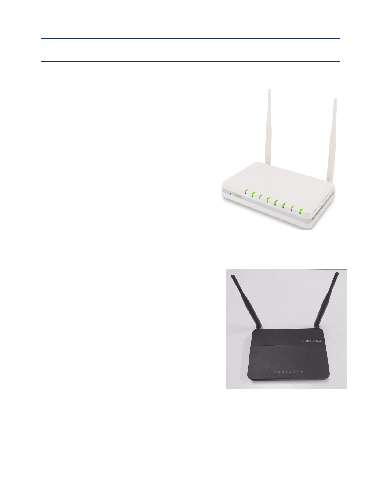
· FWR9202/FWR9601
· LED Indicators and Interfaces
· Hardware Installation
· Voice Prompt
Chapter 1 Product description
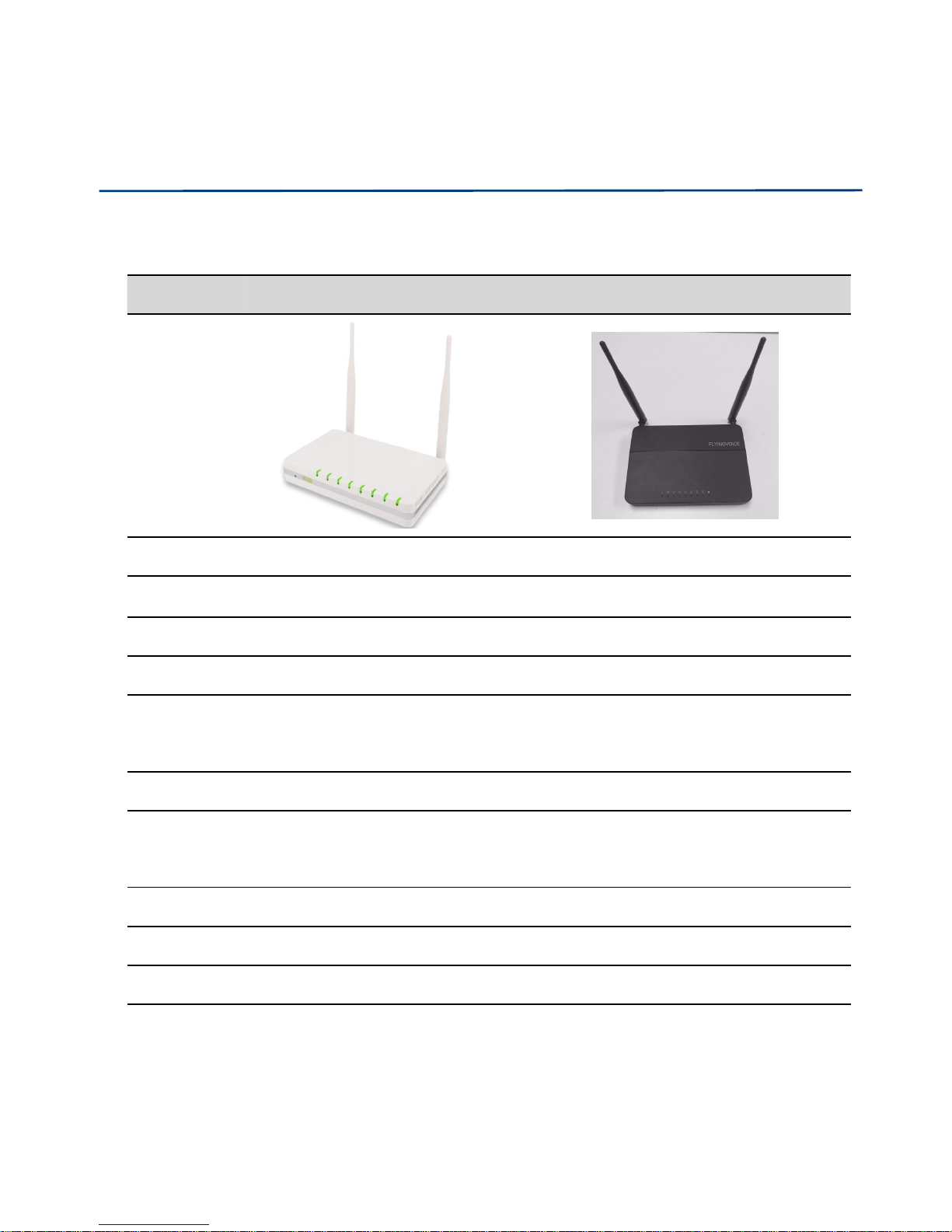
Port/Model
FWR9202
FWR9601
picture
WAN
1
1
LAN
4
4
FSX
0
1
USB
YES
NO
Ethernet
interface
5* RJ45
10/100M
5* RJ45
10/100/1000M
Fax
T.30, T.38 Fax
WiFi
2.4G 2T2R (300Mbps)
5G 2T2R (867Mbps)
2.4G 2T2R(300Mbps)
5G 2T2R (867Mbps)
Voice Code
G.711 (A-law, U-law), G.729A/B, G.723, G.722 (Wide band)
Management
Voice menu, Web Management, Provision:TFTP/HTTP/HTTPS, TR069, SNMP
VLAN
Support
FWR9202/FWR9601
Table 1 Features at-a-glance

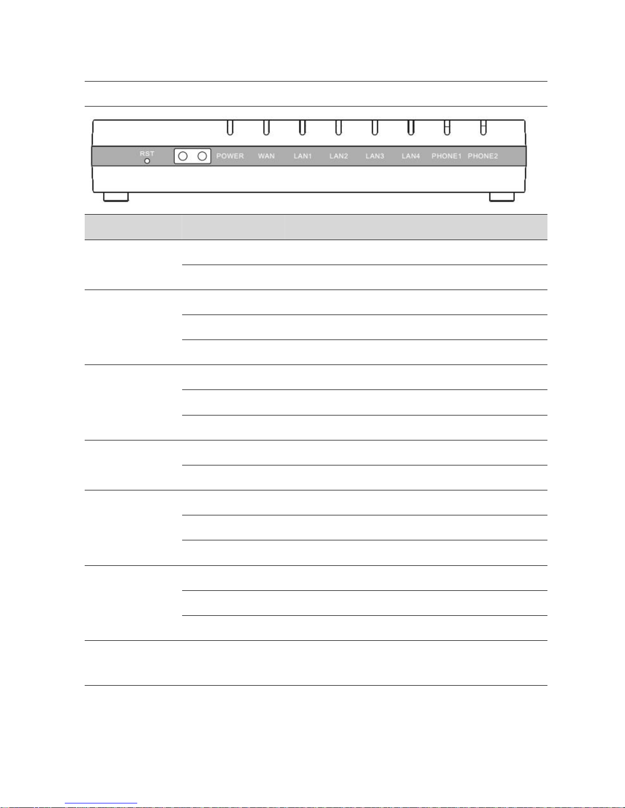
Chapter 1 Product description
LED
Status
Explanation
POWER
On (Green)
The router is powered on and running normally.
Off
The router is powered off.
WAN
On (Green)
The port is connected with 100Mbps.
Off
The port is disconnected.
Blinking (Green)
It will blink while transmitting data.
LAN1/2/3/4
On (Green)
The port is connected with 100Mbps.
Off
The port is disconnected.
Blinking (Green)
It will blink while transmitting data.
2.4G
On (Green)
The port is connected with 100Mbps.
Off
The port is disconnected.
Blinking (Green)
It will blink while transmitting data.
5G
On (Green
Wireless access point is ready.
Blinking (Green)
It will blink while wireless traffic goes through.
Off
The system is not powered on or the WIFI switch is off
PHONE
Blinking (Green)
Not registered
On (Green)
Registered
LED Indicators and Interfaces
Table 2 LED Indicators
Chapter 1 Product description
FWR9202
LED
Status
Explanation
PHONE1/2
Blinking (Green)
Not registered
On (Green)
Registered
LAN1/2/3/4
On (Green)
The port is connected with 1000Mbps.
Off
The port is disconnected.
Blinking (Green)
It will blink while transmitting data.
WAN
On (Green)
The port is connected with 1000Mbps.
Off
The port is disconnected.
Blinking (Green)
It will blink while transmitting data.
POWER
On (Green)
The router is powered on and running normally.
Off
The router is powered off.
2.4G
On (Green)
The port is connected with 1000Mbps.
Off
The port is disconnected.
Blinking (Green)
It will blink while transmitting data.
5G
On (Green
Wireless access point is ready.
Blinking (Green)
It will blink while wireless traffic goes through.
Off
The system is not powered on or the WIFI switch is off
RST
Restore the factory settings button, press and hold the device after 5s to restore
the factory settings
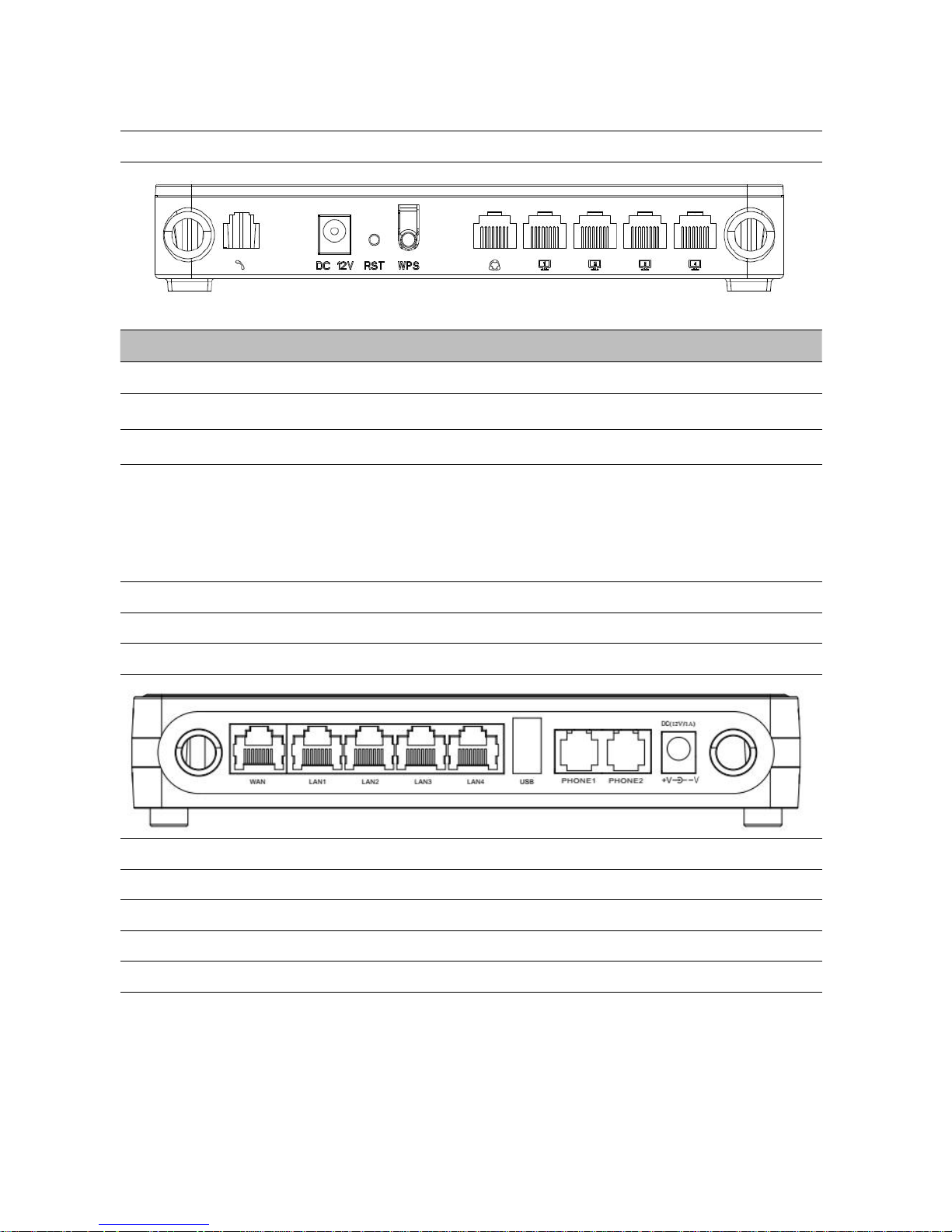
Chapter 1 Product description
FWR9601
Interface
Description
Phone1
ATA Analog phone connector
POWER
Connector for a power adapter
RESET
Restore the factory settings button, press and hold the device after 5s to restore
WPS
Wi-Fi security settings, when mobile phones, laptops and other wireless devices to
find the wireless router WiFi signal, when connected, click the WPS button on the
router to complete the wireless router and wireless device encryption
authentication and connection.
WAN
Connector for accessing the Internet
LAN 1/2/3/4
Connectors for local networked devices
FWR9202
POWER
Connector for a power adapter
Phone1/2
ATA Analog phone connector
USB
Connect USB
LAN 1/2/3/4
Connectors for local networked devices
WAN
Connector for accessing the Internet
Table 3 Interfaces

Chapter 1 Product description
1.
Connect analog phone to ATA Port with an RJ11 cable.
2.
Connect the WAN port to the Interne your network’s modem/switch/router/ADSL
3.
equipment using an Ethernet cable.
4.
Connect one end of the power cord to the power port of the device. Connect the other end to the
5.
Check the Power, WAN, and LAN LED to confirm network connectivity.
Warning
Please do not attempt to use unsupported power adapters and do not remove power during
configuring or updating the device. Using other power adapters may damage theFWR8102
Hardware Installation
Before configuring your router, please see the procedure below for instructions on connecting the device in
your network.
Procedure 1 Configuring the Router
wall outlet.

Chapter 1 Product description
Warning
Changes or modifications not expressly approved by the party responsible for
compliance can void the user’s authority to operate the equipment.
This equipment has been tested and found to comply with the limits for a Class B digital
device, pursuant to Part 15 of the FCC Rules. These limits are designed to provide reasonable
protection against harmful interference in a residential installation. This equipment
generates, uses and can radiate radio frequency cause harmful interference to radio
communications. However, there is no energy and, if not installed and used in accordance
with the instructions, may guarantee that interference will not occur in a particular
installation.
If this equipment does cause harmful interference to radio or television reception, which can
be determined by turning the equipment off and on, the user is encouraged to try to correct
the interference by one or more of the following measures:
R
eorient or relocate the receiving antenna.
Increase the separation between the equipment and receiver.
Connect the equipment into an outlet on a circuit different from that to which the receiver
is connected.

Chapter 1 Product description
Operation
code
Menu Navigation
1
Network port
configuration
(1)
WAN Port
Connection
Type
1.
Pick up phone and press “****” to start IVR
2.
Choose “1”, and The router reports the current WAN port connection type
3.
Prompt "Please enter password”, user needs to input password and press “#”
key, if user wants to configuration WAN port connection type.
The password in IVR is same as web management interface login, the user may
use phone keypad to enter password directly
For example: WEB login password is “admin”, so the password in IVR is “admin”.
The user may “23646” to access and then configure the WAN connection port.
The unit reports “Operation Successful” if the password is correct.
4.
Prompt "Please enter password”, user needs to input password and press “#”
key if user wants to configuration WAN port connection type.
5.
Choose the new WAN port connection type (1) DHCP or (2) Static
The unit reports “Operation Successful” if the changes are successful. The router
returns to the prompt “please enter your option …”
6.
To quit, enter “*”
IVR Voice Prompt
The devices may be configured by navigating the unit’s voice menu. By using your phone and
dialing a sequence of commands, the device can be configured for operation. Each device
configuration section may be accessed by entering a certain operation code, as shown below.
Table 4 IVR Menu Setting Options

Chapter 1 Product description
(2)
WAN Port IP
Address
1.
Pick up phone and press “****” to start IVR
2.
Choose “2”, and The router reports current WAN Port IP Address
3.
Input the new WAN port IP address and press “#” key:
4.
Use “*” to replace “.”, for exampleuser can input 192*168*20*168 to set the
new IP address 192.168.20.168
5.
Press # key to indicate that you have finished
6.
Report “operation successful” if user operation is ok.
7.
To quit, enter “**”.
(3)
WAN Port
Subnet Mask
1.
Pick up phone and press “****” to start IVR
2.
Choose “3”, and router reports current WAN port subnet mask
3.
Input a new WAN port subnet mask and press # key:
4.
Use “*” to replace “.”, user can input 255*255*255*0 to set the new WAN
port subnet mask 255.255.255.0
5.
Press “#” key to indicate that you have finished
6.
Report “operation successful” if user operation is ok.
7.
To quit, enter “**”.
(4)
Gateway
1.
Pick up phone and press “****” to start IVR
2.
Choose “4”, and the router reports current gateway
3.
Input the new gateway and press “#” key:
4.
Use “*” to replace “.”, user can input 192*168*20*1 to set the new gateway
192.168.20.1.
5.
Press “#” key to indicate that you have finished.
6.
Report “operation successful” if user operation is ok.
7.
To quit, press “**”.

Chapter 1 Product description
(5)
DNS
1.
Pick up phone and press “****” to start IVR
2.
Choose “5”, and the router reports current DNS
3.
Input the new DNS and press # key:
4.
Use “*” to replace “.”, user can input 192*168*20*1 to set the new gateway
192.168.20.1.
5.
Press “#” key to indicate that you have finished.
2
Phone port
configuration
1. Pick up phone and press “****” to start IVR
2. Select "2", then the device will continue to broadcast prompts the user to select
current phone number; 2. registration server address; 3. registration port; 4. call
forwarding configuration,5. DNS configuration ;
3. Continue pressing "1" and the unit will continue to broadcast the phone number
of the current phone port. The device will then broadcast "1. Phone number ..."
again.
3
F
actory Reset
1.
Pick up phone and press “****” to start IVR
2.
Choose “3”, and the router reports “Factory Reset”
3.
Prompt "Please enter password", the method of inputting password is the same
as operation 1.
4.
If you want to quit, press “*”.
5.
Prompt “operation successful” if password is right and then the router will be in
factory default configuration.
4
Reboot
1.
Pick up phone and press “****” to start IVR
2.
Choose “4”, and the router reports “Reboot”
3.
Prompt "Please enter password", the method of inputting password is same as
operation 1.
4.
the router reboots if password is right and operation
5
W
AN Port
Login
1.
Pick up phone and press “****” to start IVR
2.
Choose “5”, and the router reports “WAN Port Login”
3.
Prompt "Please enter password", the method of inputting password is same as
operation 1.
4.
If user wants to quit, press “*”.

Chapter 1 Product description
15
6
WEB Access
Port
1.
Pick up phone and press “****” to start IVR
2.
Choose “6”, and the router reports “ WEB Access Port”
3.
Prompt “Please enter password”, the method of inputting password is same as
operation 1.
4.
Report “operation successful” if user operation is ok.
5.
Report the current WEB Access Port
7
F
irmware
Versio
n
1.
Pick up phone and press “****” to start IVR
2.
Choose “7” and the router reports the current Firmware version

Chapter 1 Product description
16
Note
1.While using Voice menu, press * (star) to return to main menu.
2.If any changes made in the IP assignment mode, the router must be rebooted in order
for the settings to take effect.
3.While entering an IP address or subnet mask, use "*" (star) to enter "." (Dot) and use
"#" (hash) key to finish entering IP address or subnet mask:
4.For example, to enter the IP address 192.168.20.159 by keypad, press these keys:
192*168*20*159, use the #(hash) key to indicate that you have finished entering the
IP address.
5.Use the # (hash) key to indicate that you have finish entering the IP address or subnet
mask
6.While assigning an IP address in Static IP mode, setting the IP address, subnet mask
and default gateway is required to complete the configuration. If in DHCP mode,
please make sure that a DHCP server is available in your existing broadband
connection to which WAN port of FWR8102 is connected.
7.The default LAN port IP address of FWR8102 is 192.168.11.1 and this address should
not be assigned to the WAN port IP address of FWR8102 in the same network segment
of LAN port.
8.The password can be entered using phone keypad, the mapping table between number
and letters as follows:
To input: D, E, F, d, e, f -- press ‘3’
To input: G, H, I, g, h, i -- press ‘4’
To input: J, K, L, j, k, l -- press ‘5’
To input: M, N, O, m, n, o -- press ‘6’
To input: P, Q, R, S, p, q, r, s -- press ‘7’
To input: T, U, V, t, u, v -- press ‘8’
To input: W, X, Y, Z, w, x, y, z -- press ‘9’
To input all other characters in the administrator password-----press ‘0’,

17
This chapter covers:
Two-Level Management
Web Management Interface
Configuring
Making a Call
Chapter 2 Basic Settings
Chapter 2 Basic Settings
18
(1) administrator mode operation: please type “admin/admin” on Username/Password and click Login
(2) user mode operation, please type “user/user” on Username/Password and click Login button to begin
Two-Level Management
This section explains how to setup a password for an administrator or user and how to adjust basic and
advanced settings.
FWR9202/FWR9601 supports two-level management:
button to begin configuration.
configuration.
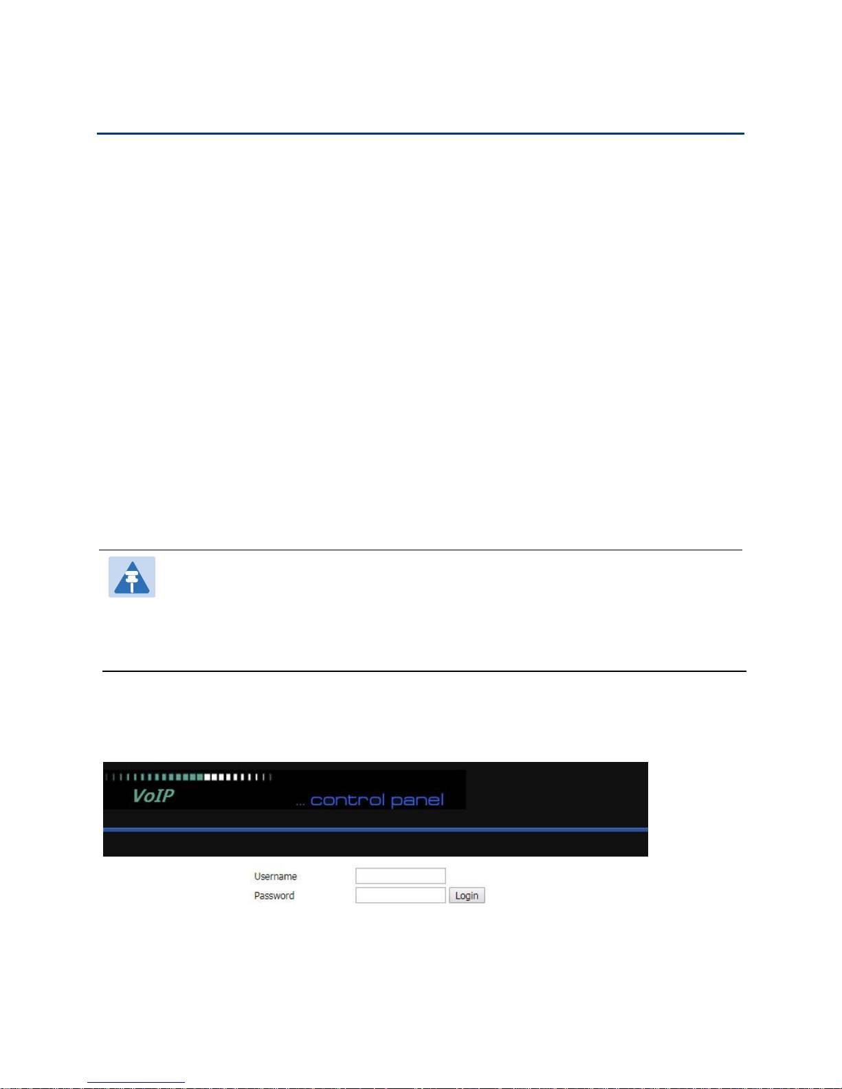
Web Management Interface
The devices feature a web browser-based interface that may be used to configure and manage the device.
See below for information
Login in from the LAN port
1.Ensure your PC is connected to the router’s LAN port correctly.
Note
You may either set up your PC to get an IP dynamically from the router or set up
address of the PC to be the same subnet as the default IP address of router is 192.168.1.1.
For detailed information, see Chapter 5: Troubleshooting Guide.
2.Open a web browser on your PC and type “http://192.168.1.1”.
3.The following window appears and prompts for username , password.
the IP
4.For administrator mode operation, please type admin/admin on Username/Password and click Login to
begin configuration.
5.For user mode operation, please type user/user on Username/Password and click Login to begin
configuration.
Chapter 2 Basic Settings
19
Note
If you are unable to access the web configuration, please see Chapter 5: Troubleshooting
Guide for more information.
Note
If you fail to access to the web configuration, see Chapter 6: Troubleshooting Guide for
more information.
6.The web management interface automatically logs out the user after 5 minutes of inactivity.
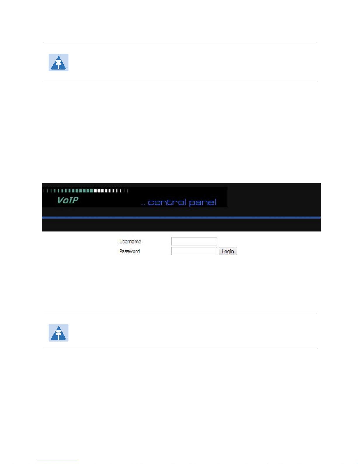
Login in from the WAN port
1.Ensure your PC is connected to the router’s WAN port correctly.
2.Obtain the IP addresses of WAN port using Voice prompt or by logging into the device web management
interface via a LAN port and navigating to Network > WAN.
3.Open a web browser on your PC and type http://<IP address of WAN port>. The following login page will
be opened to enter username and password.
4.For administrator mode operation, type admin/admin on Username/Password and click Login to begin
configuration.
5.For user mode operation, type user/user on Username/Password and click Login to begin configuration.
6.The web management interface automatically logs out the user after 5 minutes of inactivity.
Chapter 2 Basic Settings
20
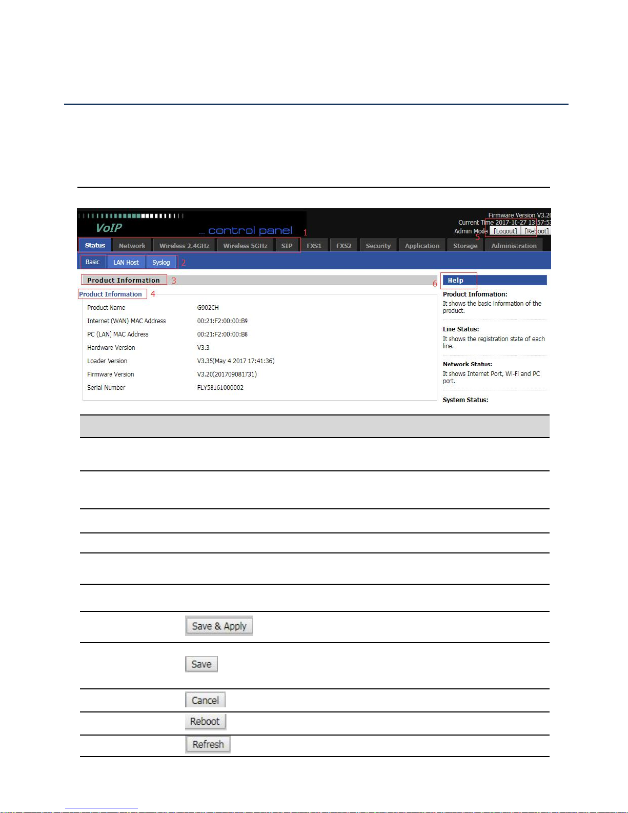
Web Management Interface Details
Serial number
Name
Description
Postition 1
Main navigation bar
Click this navigation bar to bring up the corresponding
child navigation bar
Postition 2
navigation bar
Click the sub navigation bar to enter the configuration
page
Postition 3
Product Information
Device Information Configuration Title
Postition 4
Product Information
Show product information
Postition 5
Login/Logout
main information shows the firmware version, DSP
version, current time and management mode.
Postition 6
Help
help to display help information, users can get some help
here
Use this button,conifg will be saved and And take effect
immediately
After changing the parameters, you need to click this
button to save. After you click Save, there is a need to
restart the device.
Click to cancel the change
Click to restart
Refresh current page
Satus
Table 5 Web management interface
Chapter 2 Basic Settings
21
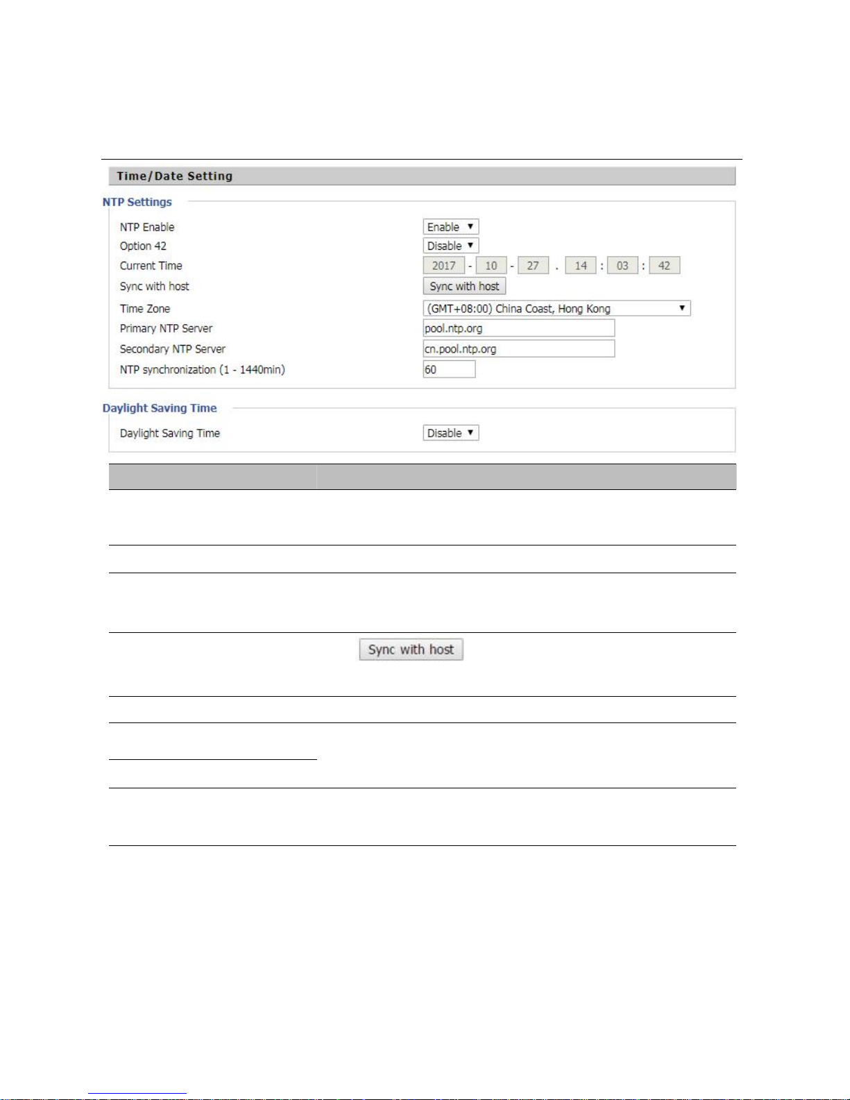
Field Name
Description
NTP Enable
Enable NTP (Network Time Protocol) to automatically retrieve time
and date settings for the device
Option 42
Whether to enable Option 42
Current Time
When NTP Enable is set to “Disable”, manually configure the time
and date via the Current Time parameter
Sync with host
Press button to synchronize the host PC
date, time and time zone.
Time Zone
Select the desired time zone
Primary NTP Server
Primary and secondary NTP server address for clock
synchronization. A valid NTP server must be reachable for full NTP
Secondary NTP Server
NTP Synchronization(1 -
1440min)
The synchronization period with NTP (1-1440 minutes), default is
60
Setting the Time Zone
Table 6 Setting time zone
Chapter 2 Basic Settings
22
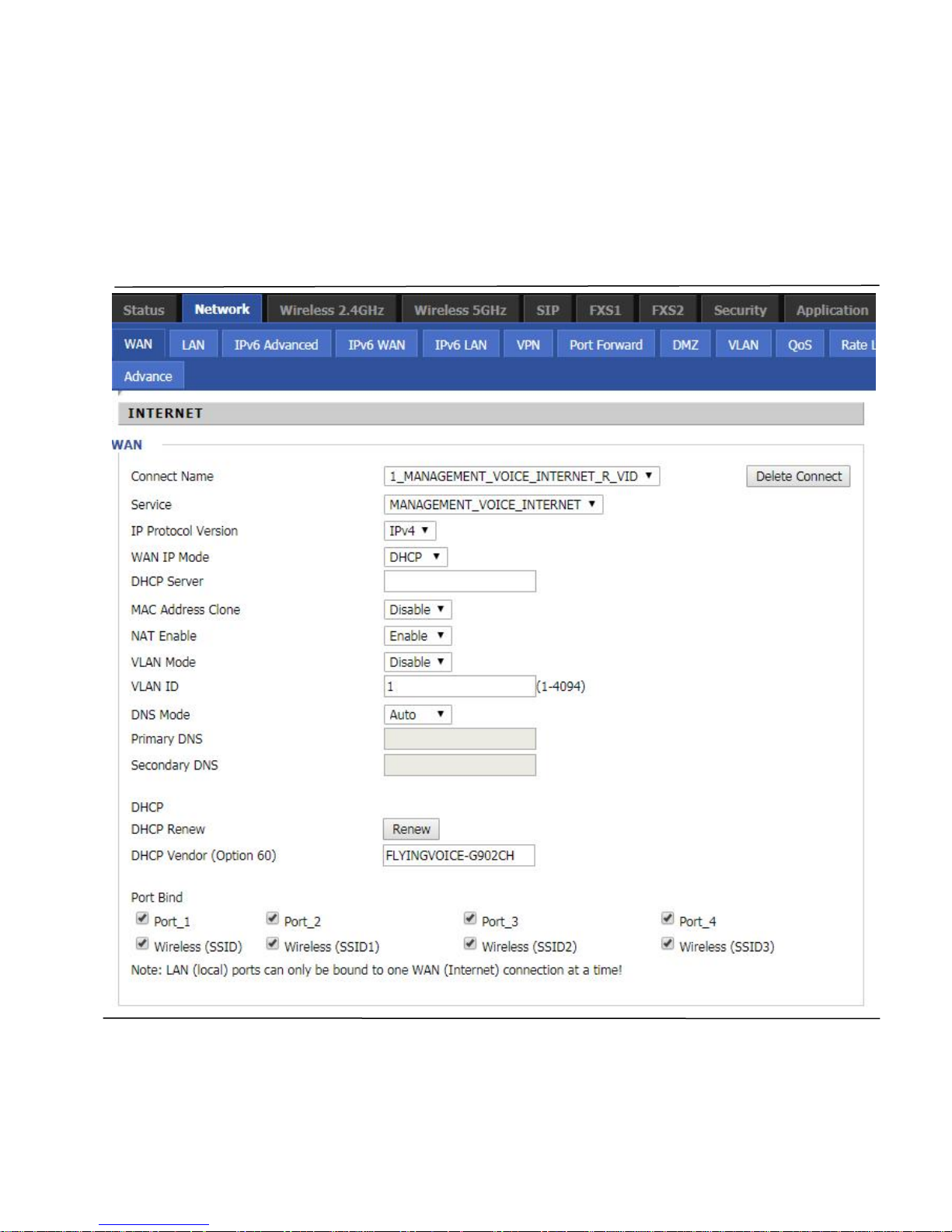
Configuring an Internet Connection
From the Network > WAN page, WAN connections may be inserted or deleted. For more information on
Internet Connection setting, see Table 10below.
Table 7 Configuring an internet connection
 Loading...