

FlyingThingZ M1A1 Flying Tank Assembly Manual
M1A1 Flying Tank
A Sport Scale Flying Military Tank
Specifications
Wingspan: 24"
Wing Area: 864 sq in
Weight: 7 lbs.
Radio: 4 Channel w/ Elevon Mixing
Engine: .46 - .61 two-stroke / .53 - .71 four-stroke
The M1A1 Flying Tank is fun and easy to build. We have done all the hard work for you. It can easily be framed up and covered in a weekend. While it may look a little bit different, the construction
techniques used are the same as most other airplanes. The average modeler will have no problem. You
will find top quality Laser Cut balsa, plastic and plywood, as well as beautiful CNC Cut foam cores
and parts! It is the ultimate high tech kit!
Low speed flying is great, with huge elevons and tons of surface area, it will crawl along with
full control and amazing stability. To speed up all you need to do is give it gas! It flies smooth, stable, and responds great. Most say that it flies like a low wing sport plane. Landings are breeze, just
lower the throttle and she’ll settle in on her own. All in all you can't find a plane that gets you more
attention and is as fun to fly.
Copyright © 2010 Kit# FTZ3015

Table of Contents
Warranty Information. . . . . . . . . . . . . . . . . . . . . . . . . . . . . . . . . . . . . . . . . . . . . . . . . . . . . . . . . . . . . . . . . . . . . . . . . . . . . . . . .3
Warnings and Safety Precautions. . . . . . . . . . . . . . . . . . . . . . . . . . . . . . . . . . . . . . . . . . . . . . . . . . . . . . . . . . . . . . . . . . . . . . . 3
efore Starting Assembly. . . . . . . . . . . . . . . . . . . . . . . . . . . . . . . . . . . . . . . . . . . . . . . . . . . . . . . . . . . . . . . . . . . . . . . . . . . . . . 3
B
Using This Manual. . . . . . . . . . . . . . . . . . . . . . . . . . . . . . . . . . . . . . . . . . . . . . . . . . . . . . . . . . . . . . . . . . . . . . . . . . . . . . . . . . . 4
Kit Contents. . . . . . . . . . . . . . . . . . . . . . . . . . . . . . . . . . . . . . . . . . . . . . . . . . . . . . . . . . . . . . . . . . . . . . . . . . . . . . . . . . . . . . . . .4
Additional Requirements. . . . . . . . . . . . . . . . . . . . . . . . . . . . . . . . . . . . . . . . . . . . . . . . . . . . . . . . . . . . . . . . . . . . . . . . . . . . . .5
Required Tools and Adhesives. . . . . . . . . . . . . . . . . . . . . . . . . . . . . . . . . . . . . . . . . . . . . . . . . . . . . . . . . . . . . . . . . . . . . . . . .5
Fuselage Assembly. . . . . . . . . . . . . . . . . . . . . . . . . . . . . . . . . . . . . . . . . . . . . . . . . . . . . . . . . . . . . . . . . . . . . . . . . . . . . . . . . . .. 6
Preparing the Foam.. . . . . . . . . . . . . . . . . . . . . . . . . . . . . . . . . . . . . . . . . . . . . . . . . . . . . . . . . . . . . . . . . . . . . . . . . . . . . . . . . 1 0
Wing Assembly.. . . . . . . . . . . . . . . . . . . . . . . . . . . . . . . . . . . . . . . . . . . . . . . . . . . . . . . . . . . . . . . . . . . . . . . . . . . . . . . . . . . . . 1 0
Elevon Assembly. . . . . . . . . . . . . . . . . . . . . . . . . . . . . . . . . . . . . . . . . . . . . . . . . . . . . . . . . . . . . . . . . . . . . . . . . . . . . . . . . . . . 1 3
Coroplast Parts Assembly. . . . . . . . . . . . . . . . . . . . . . . . . . . . . . . . . . . . . . . . . . . . . . . . . . . . . . . . . . . . . . . . . . . . . . . . . . . . 1 3
Final Assembly. . . . . . . . . . . . . . . . . . . . . . . . . . . . . . . . . . . . . . . . . . . . . . . . . . . . . . . . . . . . .. . . . . . . . . . . . . . . . . . . . . . . . . 1 3
Radio Setup. . . . . . . . . . . . . . . . . . . . . . . . . . . . . . . . . . . . . . . . . . . . . . . . . . . . . . . . . . . . . . . . . . . . . . . . . . . . . . . . . . . . . . . .. 1 6
Control Throws & CG. . . . . . . . . . . . . . . . . . . . . . . . . . . . . . . . . . . . . . . . . . . . . . . . . . . . . . . . . . . . . . . . . . . . . . . . . . . . . . . 1 7
Pre-Flight Checklist. . . . . . . . . . . . . . . . . . . . . . . . . . . . . . . . . . . . . . . . . . . . . . . . . . . . . . . . . . . . . . . . . . . . . . .. . . . . . . . . . . 1 7
Flight Characteristics. . . . . . . . . . . . . . . . . . . . . . . . . . . . . . . . . . . . . . . . . . . . . . . . . . . . . . . . . . . . . . . . . . . . . . . . . . . . . . . . 1 8
2004 AMA Safety Code. . . . . . . . . . . . . . . . . . . . . . . . . . . . . . . . . . . . . . . . . . . . . . . . . . . . . . . . . . . . . . . . . . . . . . . . . . . . . .. 1 8
2

Warranty Information
FlyingThingZ, Inc. guarantees this model to be free from defects in material and workmanship at the date of purchase. This warranty
does not cover any parts damaged by use or modifications. In no way shall FlyingThingZ, Inc. liability exceed the original cost of the
purchased model. Further, FlyingThingZ, Inc. reserves the right to modify this warranty without prior notice.
In that FlyingThingZ, Inc. has no control over the final stages of assembly or material used for the final assembly, no liability shall be
assumed nor accepted for any damage of the final user-assembled product. By the act of using the final product, the user accepts all
esulting liability.
r
We, as a kit manufacture, provide you with a top quality kit and manual, but the quality and flying characteristics of your finished model
depend on how you build it; therefore, we cannot in any way guarantee the performance of your completed model and no representations are expressed or implied as to the performance or safety of your completed model.
If the buyer is not prepared to accept the liability associated with the use of this product, the buyer is advised to return this kit immediately, in new and unused condition, to the place of purchase.
Warnings and Safety Precautions
READ THROUGH THIS MANUAL BEFORE STARTING ASSEMBLY. IT CONTAINS IMPORTANT WARNINGS AND
INSTRUCTIONS CONCERNING THE ASSEMBLY AND USE OF THIS MODEL.
AN RC AIRCRAFT IS NOT A TOY! IF MISUSED, IT CAN CAUSE SERIOUS BODILY HARM AND DAMAGE TO PROPERTY.
FLY ONLY IN OPEN AREAS, PREFERABLY AT AMA (www.modelaviation.com) APPROVED SITES. FOLLOW ALL INSTRUCTIONS INCLUDED WITH YOUR RADIO AND ENGINE.
You must assemble the model according to the instructions. Do not alter or modify the model, as doing so may result in an unsafe
or unstable aircraft. In a few cases the instructions may differ slightly from the images provided. In these cases, the written instructions
should take precedence.
Take your time to build straight, true and strong.
You must use an R/C radio system that is specifically designed for aircraft frequencies, properly tuned and in first class working
condition. The correctly sized engine displacements and miscellaneous components should be used throughout the building process as
specified on this manual.
Check the operation of your model before each flight and insure that all equipment is fully operational and all hardware is secure.
Be sure to check all linkage connections and parts that may become dislodged during flight.
This kit is not intended as a trainer. If you are not an experienced pilot, you should fly the model only with the help and supervision of a competent, experienced R/C pilot.
Before Starting the Assembly Process
Before beginning assembly of the M1A1 Flying Tank, remove all parts from their packages for inspection. Inspect all hardware, fuselage parts, wing components and foam for damage. If you find any damaged or missing parts, please contact us directly.
FlyingThingZ, Inc.
2075 Grandview St.
Oceanside, CA 92054
www.flyingthingz.com
support@flyingthingz.com
3
Using This Manual
This manual is divided into sections to aid in the assembly process. It provides an easier more concise layout allowing for breaks
between each major section. Additionally, check boxes have been provided next to each step to help keep track of the completed
assembly process. Steps with two check boxes indicate that the step is repeated, such as for a right and left wing panel, control link-
ges or fuselage side. Remember to take your time and follow the directions carefully.
a
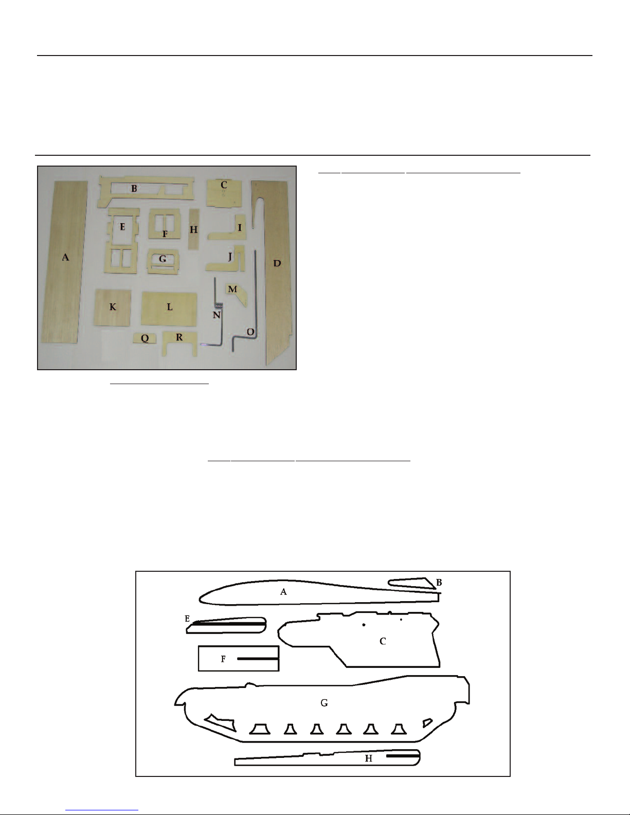
Kit Contents
Part# Description Qty.
A Fuselage Hatch 1
B Fuselage Reinforcements 2
C Firewall 2
D Fuselage Sides 2
E Rear Servo Tray 1
F Forward Servo Tray 1
G Fuselage Cross Brace 1
H Hatch Tongue Plate 2
I Gear Block Piece 6
J Notched Gear Block Piece 2
K Rear Fuselage Plate 1
L Lower Ply Fuselage Plate 1
M Control Horn 2
N Nose Landing Gear 1
Wood Parts Not Shown
1/2” x 18” Balsa Triangle
1/16” x 4” x 36” Balsa Sheet
1/4” x 1/4” x 36” Balsa Stick
1/4” x 36” Wood Dowel
O Main Landing Gear 2
Q Hatch Tongue 1
R Hatch Bolt Plate 1
Ply Disks 4 (not shown)
Part# Description Qty.
A Wing Core 1
B Elevons 1
C Tank Turret 2
E Canon Reinforcements 4
F Canon Base 1
G Tank Sides 2
H Canon 2
4

Additional Kit Contents (Not Shown)
Part Description Qty.
3/4” x 4-40 Bolts 1
4-40 Blind Nuts & Washers 1
anding Gear Straps 4
L
Nose Gear Hardware 1
#2 x 9/16 Wood Screws 2
5/32” Wheel Collars 6
Additional Kit Requirements
3 2.5” to 3” Wheels
Motor Mount and Mounting Hardware
2’ Medium Fuel Tubing
Prop Suited to Engine
2” Filament Strapping Tape
Engine - .40 to .60 two-stroke or .45 to .72 four-stroke
Rubber Foam
Low Temperature Covering Material
Thin, Medium and Thick CA
5 minute and 30 minute Epoxy
CA Accelerator
White or Carpenter’s Wood Glue
Small Square
#120, #220, #320 Sand Paper
Sanding Block
Hobby Knife with Extra #11 Blades
Pen, Pencil or Marker
Assorted Screw Drivers
Building Pins
Razor Saw
Miter Box
Masking Tape
Clamps or Clothespins
Wire Cutters
FlyingThingZ Pre-cut Self Adhesive Vinyl Covering
Clear Packing Tape
4 2-56 Pushrods
8oz. Fuel Tank
2” Spinner
4 Channel Radio with Elevon Mixing
3M Super 77 Spray Adhesive
Required Tools and Adhesives
Needle Nose Pliers
Scissors
Wax Paper
Paper Towels
Ruler
Mixing Sticks
Threadlock
Denatured Alcohol
Rotary Tool or Dremel
Router Attachment for Rotary Tool or Dremel
Rubber Bands
Dead Center Engine Mount Locator
Hex Wrench Set
Drill Bits (1/16” 3/32” 1/8” 5/64” and 1/2” bits)
Electric Drill
Unless a specific glue is specified, use your best judgement when joining parts.
CA WILL EAT FOAM. DO NOT USE CA TO BOND ANY PARTS TO FOAM.
Most of the tools listed herein come in handy when assembling parts provided by this kit. Although they are not all necessarily
required, they do make the process easier. You may substitute tools and other equipment listed here as long as they serve the same
purpose in a similar fashion.
5
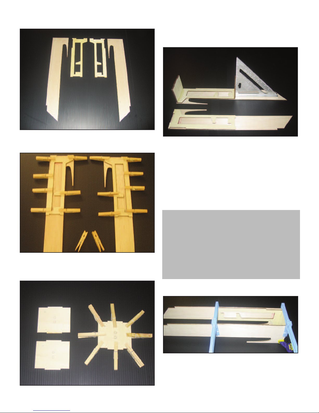
A. Fuselage Assembly
A1. Start by lining up the two fuselage sides and the two ply
fuselage reinforcements. Take note of the orientation to assure a
right and left fuselage side is created when assembled.
A3. Glue the two ply firewall pieces utilizing clothe pins to
hold the parts together. Verify the orientation of the holes on the
firewall as they will play a vital role later on.
A4. Glue the fuselage cross brace to the back of the fuselage
reinforcement. Assure that the brace lines up with the notches on
the back of the reinforcement. Use a square to assure the brace is
90-deg. to the fuselage side.
A5. In the same fashion, glue the firewall to the front of the
fuselage reinforcement. Assure that the firewall lines up with the
notches in the front of the reinforcement. Again, use a square to
assure it’s at a perfect 90-deg. angle to the fuselage. The small hole
on the firewall should be on the top left when laid out as shown in
the photo above.
A2. Utilizing cloths pins, glue the fuselage reinforcements
onto the two fuselage sides. Line up the edges of the reinforcements until they are flush with the three edges of the fuselage
sides.
6
Hints and Tips
You can substitute rubber bands or masking tape to hold parts
together. Flat parts can be sandwiched between books; just make
sure they don’t get stuck to the books.
You can make your own square by cutting a triangle out of cardboard exactly at 3” x 4” x 5”. If your measurements are correct,
this should make a perfect 90-deg angle.
Cut several paper towels into 4 pieces and soak them in alcohol.
Store them in a plastic zip bag to keep them from drying out. You
can use them to wipe up any excess epoxy while you work.
A6. Using clamps, glue the two fuselage sides together. The
firewall and cross brace should line up with the notches on the
other side of the fuselage reinforcement. Make sure pressure is
applied where the cross brace and the firewall meet the fuselage
sides. Make sure to apply pressure on the bottom part of the firewall as well to create a strong bond.
 Loading...