

Page 1
Stereo Power Amplifier
Owner’s Manual
MA–S160
Thank you for purchasing the MA–S160.
In order to use the product in a safe manner, please read this Owner’s
Manual thoroughly before using.
Also, keep this manual for future reference.
Before proceeding with the setup, make sure that the following accessory is included in the package.
If it is missing, please contact the dealer whom you purchased the amplifier from, or Flying Mole Corp.
Accessory Checklist
• Owner's Manual
(this booklet) x 1
• AC Power Cable x 1
• Remote Connection
Cable (2m) x 1
• Remote Power Control
Connector x 2
Safety Instructions
1
CAUTION
r t
i
y u
r
RISK OF ELECTRIC SHOCK
DO NOT OPEN
CAUTION :
WARNING : To reduce the risk of fire or electric shock, do not expose this apparatus to rain or moisture.
TO REDUCE THE RISK OF ELECTRIC SHOCK, DO NOT REMOVE COVER (OR BACK). NO USER-SERVICE
ABLE PARTS INSIDE. REFER SERVICING TO QUALI-FIED SERVICE PERSONNEL.
THIS SYMBOL INDICATES THAT DANGEROUS
VOLTA GE CONSTITUTING A RISK OF ELECTRIC
SHOCK IS PRESENT WITHIN THIS UNIT.
THIS SYMBOL INDICATES THAT THERE ARE IMPORTANT OPERATING AND MAINTENANCE INSTRUCTIONS IN THE OWNER’S MANUAL WITH THIS UNIT.
■ The important safety instructions
1. Read these instructions.
2. Keep these instructions.
3. Heed all warnings.
4. Follow all instructions.
5. Do not use this apparatus near water.
6. Clean only with dry cloth.
7. Do not block any ventilation openings. Install in accordance with the manufacturer’s instructions.
8. Do not install near any heat sources such as radiators, heat registers, stoves, or other apparatus (including ampli-
fiers) that produce heat.
9. Do not defeat the safety purpose of the polarized or grounding-type plug. A polarized plug has two blades with one
wider than the other. A grounding type plug has two blades and a third grounding prong. The wide blade or the third
prong are provided for your safety. If the provided plug does not fit into your outlet, consult an electrician for
replacement of the obsolete outlet.
10. Protect the power cord from being walked on or pinched particularly at plugs, convenience receptacles, and the
point where they exit from the apparatus.
11. Only use attachments/accessories specified by the manufacturer.
12. Use only with the cart, stand, tripod, bracket, or table specified by the manufacturer, or sold with the
apparatus. When a cart is used, use caution when moving the cart/apparatus combination to avoid
injury from tip-over.
13. Unplug this apparatus during lightning storms or when unused for long periods of time.
14. Refer all servicing to qualified service personnel. Servicing is required when the apparatus has been damaged in
any way, such as power-supply cord or plug is damaged, liquid has been spilled or objects have fallen into the
apparatus, the apparatus has been exposed to rain or moisture, does not operated normally, or has been dropped.
Features
2
●
Independent power twin monaural construction
●
Utilizing our original Bi-Phase PWM amplifier technology to realize a new level of high
sound quality with superb high-speed responsiveness and wide dynamic range
●
Fixed level (volume bypass) and Variable level are selectable
●
Connect the amplifier in bridge (BTL) connection to use it as a 300W/8Ω mono bloc
power amplifier
●
Gorgeous parts for uncompromising standards
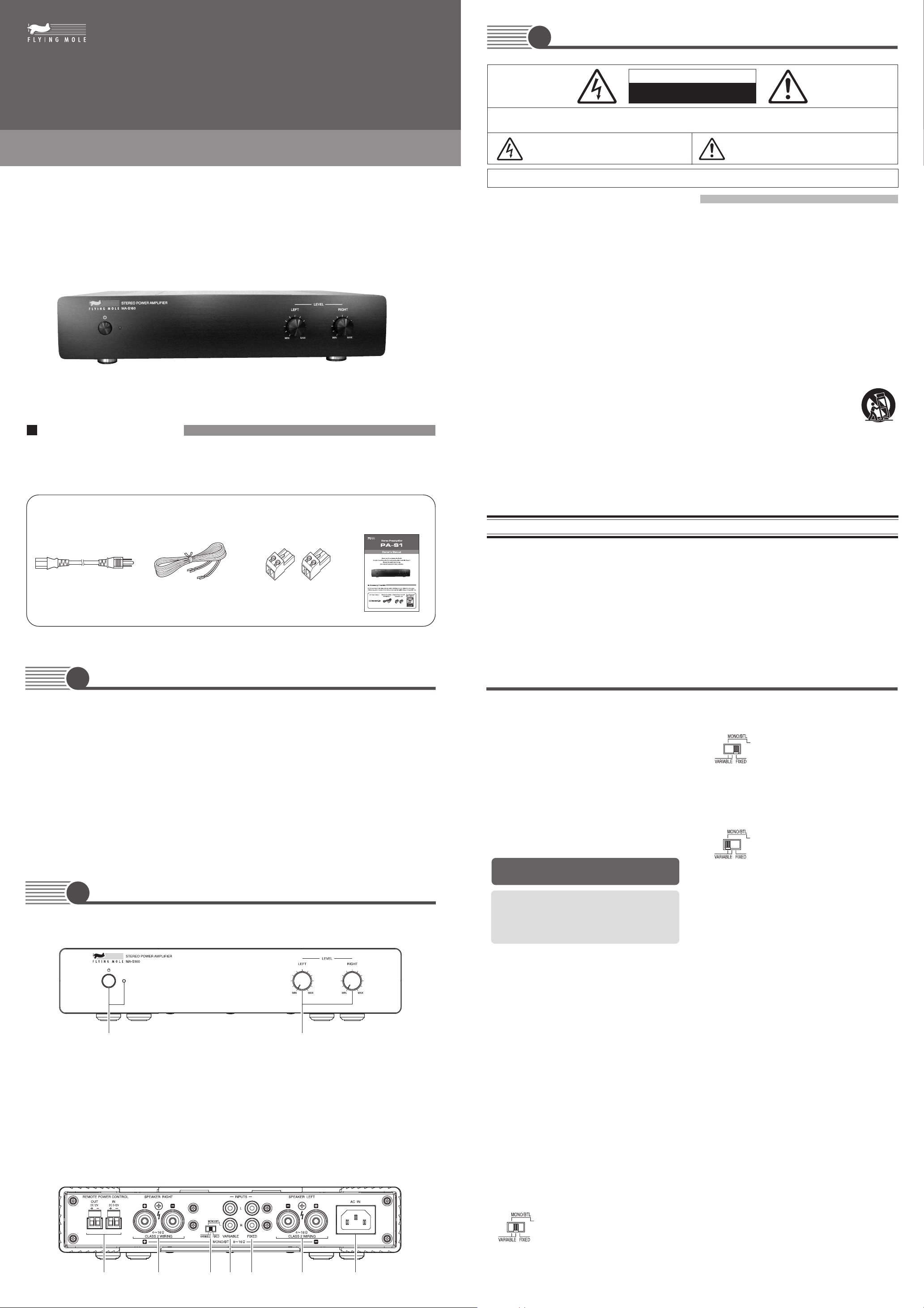
Component Names
3
■ Front Panel
q w
q Power Switch / Power Indicator
Used to turn the amplifier's power ON or OFF.
The indicator lights when the power is turned ON.
■ Rear Panel
e
w LEVEL Adjustment Knobs
Controls the input signal level.
Setting the knob to "MIN" turns down the level to
the minimum.
These knobs don't work when the Mode switch t
is set to "FIXED". When the Mode switch t is set to
"MONO/BTL", only the [RIGHT] knob will work .
THE APPARATUS IS NOT WATERPROOF. TO PREVENT FIRE OR SHOCK HAZARD, DO NOT EXPOSE THIS
APPLIANCE TO RAIN OR MOISTURE AND DO NOT PUT ANY WATER SOURCE NEAR THIS APPARATUS, SUCH
AS VASE, FLOWER POT, COSMETICS CONTAINER AND MEDICINE BOTTLE, ETC.
IMPORTANT NOTICE
If this product is found to be the source of interference, which can be determined by turning the unit “OFF” and “ON”,
please try to eliminate the problem by using one of the following measures :
Relocate either this product or the device that is being affected by the interference.
Utilize power outlets that are on different branch (circuit breaker or fuse) circuits or install AC line filter/s.
In the case of radio or TV interference, relocate/reorient the antenna.
If the antenna lead-in is 300 ohm ribbon lead, change the lead-in to coaxial type cable.
If these corrective measures do not produce satisfactory results, please contact the local retailer authorized to distribute
this type of product. If you can not locate the appropriate retailer, please contact Flying Mole Corporation.
Component Names
e REMOTE POWER CONTROL Jacks
● OUT
Remote output jacks used to interlock the power
on another device with the activation/deactivation
of the power on the amplifier.
Connect these jacks to a Flying Mole product
equipped with remote power control input jacks.
● IN
Remote input jacks used to interlock the power
on the amplifier with the activation/deactivation of
the power on another device.
Connect these jacks to a Flying Mole product
equipped with remote power control output jacks.
Turn “OFF” the power switch of the amplifier to use
the amplifier with cables connected to these jacks.
* Refer to the owner's manuals of the devices to be
connected as well.
* These jacks cannot be used with products from
other manufactures or for other purposes than the
above-mentioned purpose.
r SPEAKER Connectors (* Be sure to check po-
larity before connection)
Used to connect the amplifier to the speaker.
Connect one each speaker to the [RIGHT] and
[LEFT] connectors when the Mode switch t is set
to "FIXED" or "VARIABLE".
Make sure that the speaker's impedance is between
4 ohms and 16 ohms.
Connect one speaker to the two outermost connectors of the four [RIGHT] and [LEFT] connectors when
the Mode switch t is set to "MONO/BTL".
Make sure that the speaker's impedance is between
8 ohms and 16 ohms.
Refer to the “
r
Connections
” for details.
t Mode switch
Used to switch the operation mode of the amplifier.
Select one of the following settings according to the
connection.
● VARIABLE (Switch position: Center)
The amplifier works as a stereo power
amplifier (100W/8 ohms x 2 CH). Use
the INPUT jacks (VARIABLE) y as input jacks.
The input signal level can be adjusted
with the LEVEL adjustment knobs w
on the front panel.
● FIXED
● MONO/BTL
y INPUT Jacks (VARIABLE)
Used to connect the input signal to the amplifier.
Connect the jacks to the OUTPUT jacks on the preamplifier, etc.
One each cable can be connected to the [R] and [L]
jacks when the mode switch áD is set to "VARIABLE".
Connect only the [R] jack when the mode switch áD
is set to "MONO/BTL". These jacks are not to be used
when the mode switch áD is set to "FIXED".
u INPUT Jacks (FIXED)
Used to connect the input signal to the amplifier.
Connect the jacks to the OUTPUT jacks on the preamplifier, etc.
One each cable can be connected to the [R] and [L]
jacks when the Mode switch t is set to "FIXED".
These jacks are not to be used when the Mode switch
t is set to "VARIABLE" or "MONO/BTL".
i AC IN Jack
Used to connect the supplied AC power cable to the
amplifier.
Connect the other end of the AC power cable to
household AC outlet.
(Switch position: Right)
The amplifier works as a stereo power
amplifier (100W/8 ohms x 2 CH). Use
the INPUT jacks (FIXED) y as input
jacks.
The LEVEL adjustment knobs w on the
front panel are bypassed and inoperable.
(Switch position: Left)
The amplifier works as a monaural amplifier in BTL mode (300W/8 ohms x 1
CH). Use the [R] jack of the INPUT jacks
(VARIABLE) y as the input jack.
The input signal level can be adjusted
with the [RIGHT] knob of the LEVEL
adjustment knobs w on the front panel.
Page 2
Connections
4
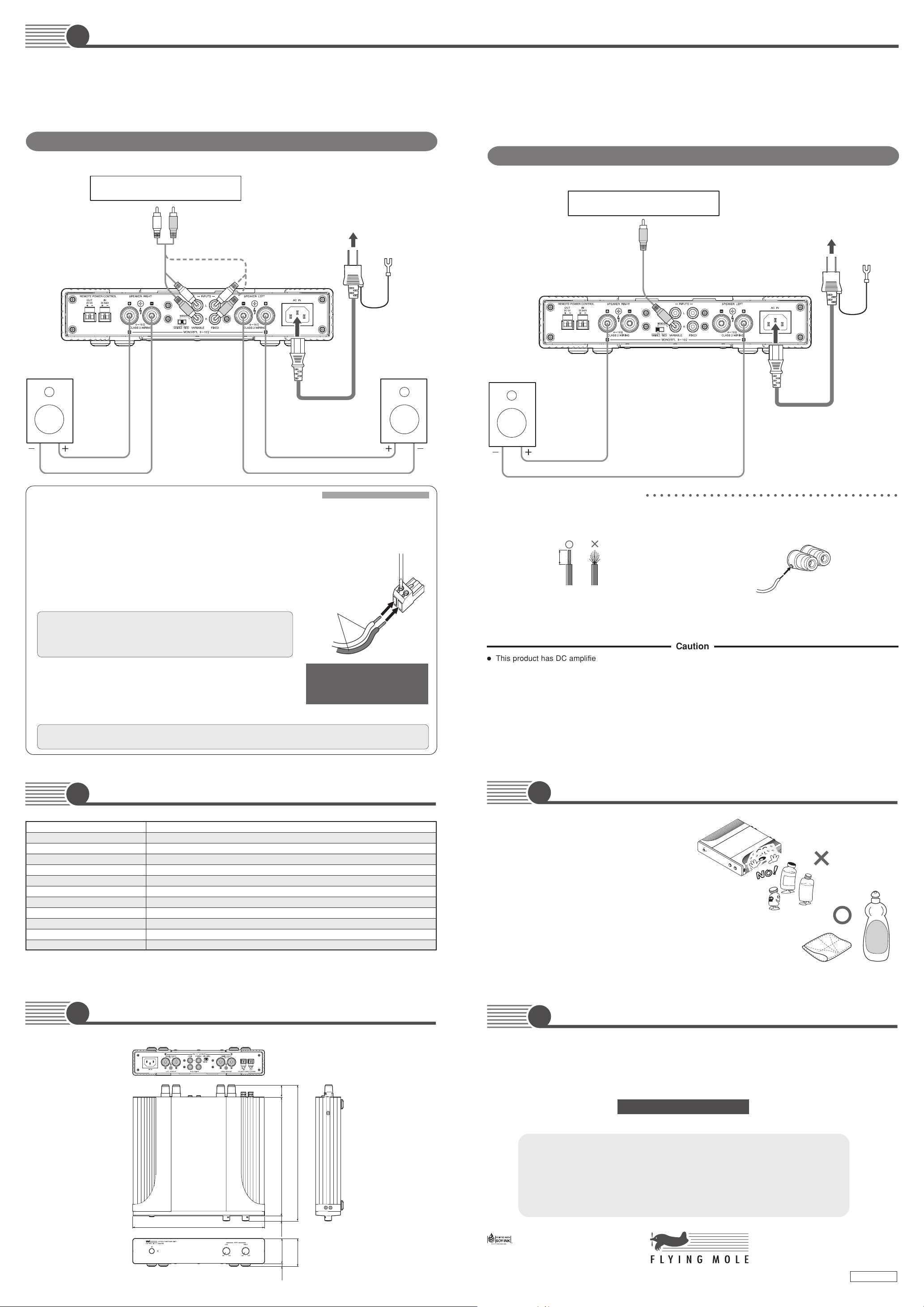
■ Connecting Devices
●
Make sure the power of all related equipments is turned off, when wiring and checking their polarity.
●
Make sure that the cable is not shorted, when connecting the speaker cable.
●
Connect the power cable after all connections are complete.
Connection example 1: Common setting for playing stereo sounds
* Set the mode switch to "VARIABLE" or "FIXED".
Preamplifier, CD Player, etc.
LINE OUT Jacks
R
(* 1) Connect to either the "VARIABLE" or
"FIXED" jacks of the INPUTS depending on the mode switch setting.
L
(* 1)
L
R
L
R
Connect to AC Outlet
Connect to
Ground Terminal
(* 2)
●
This product should be placed close to the main source of electrical power (wall outlet in your house)
and keep the power plug within reach.
●
Connectors names may be different from this manual.
✱ Refer to the owner's manuals of the equipments to be connected as well.
Connection example 2: Bridge (BTL) connection
* Set the mode switch to "MONO/BTL".
Preamplifier, CD Player, etc.
Connect to AC Outlet
Ground Terminal
Connect to
(* 2)
Speaker (R)
AC Power Cable
Speaker (L)
● Connection of the REMOTE POWER CONTROL Trigger
By connecting the REMOTE POWER CONTROL Trigger, the activation/deactivation of power on a Flying Mole
power amplifier equipped with REMOTE POWER CONTROL Trigger Input can be interlocked with the activation/deactivation of power on this device. Refer to the owner’s manuals of the devices to be connected as well
before connecting cables.
1.
Remove the attachment to the REMOTE POWER CONTROL connectors.
2. Remove insulation material around the ends of the supplied remote connection cables and twist the wires until they are stranded securely.
3. Insert the wires into the holes in the attachment and tighten the screws
to fix the cables.
* Connect the other ends of the cables to the connector for the device whose
power is to be interlocked as in the steps 1 to 3 above.
(The connector is also attached to the REMOTE POWER CONTROL jacks
of the device to be connected.)
4. DConnect the connectors to the REMOTE POWER CONTROL jacks of
the amplifier and of the other product.
•To control the power of the amplifier from the other product, connect the con-
nectors to the "IN" of this product and to the "OUT" of the other product.
•To control the power of the other product from this product, connect the con-
nectors to the "OUT" of the amplifier and to the "IN" of the other product.
* Commercially available vinyl insulated cables can be used as well. • Compatible cable type is AWG24 to AWG12.
Refer to the steps 1 through 4 above when connecting cables and make sure that the polarity is correct.
(Be sure to check polarity before connection)
Supplied remote
connection cable
* Be sure to check polarity before
connection.
Connect the black cable to the
negative terminal.
+
Speaker
AC Power Cable
(* 2) For safety purpose, a ground wire is attached
to the supplied AC cable. Be sure to connect
the ground wire to the ground terminal in the
outlet before connecting the plug to the
outlet.When disconnecting the AC cable, disconnect the power plug before disconnecting
the ground wire.
● Connecting a Speaker Cable
q Strip the cover of the cable by about 10mm (3/8”).
w Twist the wires until they are stranded securely.
10mm
*Twist the wires of the speaker cable until they are stranded securely and take care not to leave any part of the stranded wires out
–
of the speaker connector when connecting the speaker cable. If the wires come in contact with the rear panel or the wires at the
positive terminal come in contact with the wires at the negative terminal, the protection circuit may be activated to stop the normal
operation of the product.
○○○○○○○○○○○○○○○○○○○○○○○○○○○○○○○○○○○○
e Tu rn a speaker connector counterclockwise to loosen it.
r Insert the whole stranded wires of the cable and turn the
speaker connector clockwise to tighten it.
Caution
●
This product has DC amplifier circuit construction. (Sound signal goes through no capacitor from input to the speaker
output.)
Therefore, a little noise may be heard when the power is turned on or off depending on the connected device.
●
This product processes digital signals. This product may cause harmful interference to other equipment depending on
environments where they are used. If interference is caused, install the product where the interference is minimized.
In general, it is effective to keep the product as far away from the interfered equipment as possible. Bad receiving condition
may be experienced, especially if an indoor antenna or a feeder line is used for TV or radio broadcasting, because their
receiver sensitivity of airwaves tends to be low and is vulnerable to external influence. In such a case, an outdoor antenna
or a coaxial cable is recommended.
Specifications
5
Rated Output 160W x 2 / 4Ω, 100W x 2 / 8Ω, 300W x 1 / 8Ω (During bridge connection)
Total Harmonic Distortion 0.05% (@50W/8Ω/1kHz)
Frequency Response DC–20kHz (+0dB / –0.5dB) / (8Ω) DC–50kHz (+0dB / –3dB) / (8Ω)
Channel Separation >70dB (20kHz)
S/N Ratio 120dB (IHF-A)
Input Sensitivity 1V
Input Impedance VARIABLE : 47kΩ (Vol MAX), FIXED : 100kΩ
Power Consumption ?
Power Supply AC 120V 60Hz (U.S.A. & Canadian model) / AC 230V 50Hz
Use Environment 0°C – 40°C
Max. Dimensions inch / mm 11-1/16" (W) x 2-3/8" (H) x 11-7/16" (D) 281 (W) x 60 (H) x 290 (D)
Weight 4.2 kg (9.3 lbs)
* Nameplate is on the bottom of the product.
* Due to product improvement, specifications and/or product design are subject to change without notice.
Dimensions
6
25
(1”)
Maintenance
7
Never use liquids such as benzine, thinners,
etc., chemically treated cloths, and do not spray
any aerosol type insecticides on the amplifier.
Clean the case using only a soft, dry cloth.
If the amplifier becomes soiled, mix a solution
of water and a neutral detergent then dampen
a soft cloth in the solution, wring out as much
of the solution as possible, and clean the am-
plifier. Then use a soft, dry cloth to wipe the
Soft cloth
surface dry.
Questionnaire
8
There is a questionnaire in the “Support” section in our website.
This is for helping us serve you better by developing new products.
We look forward to your access to the following URL.
http://www.flyingmole.co.jp
Liquids
Benzine
Neutral
detergent
281 (11-4/16”)
254 (10”)
11
(7/16”)
54
(2-1/8”)
6
(1/4”)
290 (11-7/16”)
60
(2-3/8”)
Unit: mm (”)
Privacy Policy
Security of Collected Information
We maintains strict physical, electronic, and administrative safeguards to protect
your personal information from unauthorized or inappropriate access. We
restricts access to information about you to who need to know the information to
respond to your inquiry or request. Who misuse personal information are subject
to disciplinary action.
This document is printed with soy ink
(an organic ink made from soy oil) on
recycled paper. Environmentally
friendly printed matter.
FLYING MOLE CORPORATION
5199-1 Waji-cho, Hamamatsu 431-1115 Japan.
Tel : +81-53-486-6030 Fax : +81-53-486-6033
http://www.flyingmole.co.jp [email protected]
???????-???
 Loading...