

Flying Machines FM250 VAMPIRE Flight Manual
www.flyingmachines.cz FLYING MACHINES s.r.o. info@flyingmachines.cz
FM-250 Vampire
Flight Manual
Flight Manual Page 0 of 40

www.flyingmachines.cz FLYING MACHINES s.r.o. info@flyingmachines.cz
TABLE OF CONTENTS
SECTION
1. General
2. Limitations
3. Normal Procedures
4. Emergency Procedures
5. Performance
6. Airplane Handling, Service & Maintenance Information
7. Service life of an airplane and maintenance cycles
8. Repairs
9. Rotax 912 / 912S engine maintenance
PAGE
6
12
18
24
28
29
32
37
39
1. General
1.1 Introduction
1.2 Description
1.2.1 Airframe
1.2.2. Fuel system
1.2.3 Engine
1.2.4 Propeller
1.2.5 Landing gear
1.2.6 Controls
1.2.6.1 Movement of flight controls
1.2.7 Equipment
1.2.8 Technical drawing
1.2.9. Detecting the position of the center of gravity, permitted limits
1.2.9.1 Weighing the airplane for the headmost position of the center of gravity
1.2.9.2 Weighing the airplane for the backmost position of the center of gravity
2. Limitations
2.1 Introduction
2.2 Airspeed indicator markings
2.3 Operating speeds
2.4 Weight and load factors
2.4.1 Maximum and minimum weights
2.4.2 Load factors, flight envelope
2.5 Engine operating limitations
2.6 Fuel and lubricant oil
2.6.1 Fuel supply
2.6.2 Consumption of fuel
Flight Manual Page 1 of 40

www.flyingmachines.cz FLYING MACHINES s.r.o. info@flyingmachines.cz
2.7 Crew
2.7.1 Minimum and maximum weight of the crew
2.7.2 Pilot’s qualification
2.7.3 Pilot’s place in the plane, age of the crew, using the seat belts
2.8 Maximum flight altitude
2.9 Meteorological restrictions
2.10 Carriage of goods restrictions
2.11 Type of traffic
2.12 Restriction of maneuvers
2.12.1 Allowed turns
2.13 Other restrictions
3. Normal Procedures
3.1 Introduction
3.2 Preflight inspection
3.3 Checklists and stages of flight
3.3.1 Before starting the engine
3.3.1.1 Engine run up
3.3.2 Before take off
3.3.3 After take off
3.3.4 Climb
3.3.5 Cruise
3.3.6 Descent
3.3.7 Downwind
3.3.8 Base
3.3.9 Final
3.3.10 Landing
3.3.11 Shut down
3.4 After flight inspection
3.5 Flying with a crosswind component
3.6 Flight in turbulent air
4. Emergency Procedures
4.1 Introduction
4.2 Engine failure
4.2.1 Engine failure during take off
4.2.2 Engine failure after take off
4.2.3 Engine failure during flight
4.2.3 Airstart
4.3 Fire, fume and smoke
4.3.1 Engine fire on the ground
4.3.2 Engine fire during take off
4.3.3 Engine fire in flight
4.3.4 Cabin fire
4.4 Vibrations
4.5 Precautionary landing
4.6 Landing gear and tire failure
4.6.1 Main landing gear failure
4.6.2 Nose landing gear failure
4.6.3 Tire failure
4.7 Using the ballistic recovery system – BRS (parachute)
Flight Manual Page 2 of 40

www.flyingmachines.cz FLYING MACHINES s.r.o. info@flyingmachines.cz
5. Performance
5.1 Introduction
5.2 Speed
5.3 Rate of climb and loss of height during stall
5.4 Take off and landing distance
5.5 Flying range
5.6 Gliding ratio
5.7 Cruise
5.8 Fuel consumption
6. Airplane Handling, Service & Maintenance Information
6.1 Anchoring an airplane
6.2 Manipulation with an airplane
6.3 Rigging and de-rigging
6.3.1 De-rigging
6.3.2 Rigging
6.4 Washing and cleaning of an airplane
6.5 Filling the fuel
6.6 Placards and their locations
6.7 Stepping up on an airplane
7. Service life of an airplane and maintenance cycles
7.1 Service life of an airplane
7.2 Maintenance
7.2.1 Lubrication
7.2.2 Disassembly of the nose wheel
7.2.3 Disassembly of the main wheel
7.2.4 Tire repairs
7.2.5 Electrical installation
7.2.5.1 Electrical installation inspection
7.2.6 Spark plugs
7.2.7 Special tools
7.2.8 Minor repairs
7.2.9 Changing the fuel filter in the engine area
7.2.10 Propeller maintenance
7.2.11 Jacking points on an airplane
7.3 Introductory inspection
7.4 Periodic inspection after every 50 hours
7.5 Periodic inspection after every 100 hours
7.6 Periodic inspection after every 200 hours
7.7 Periodic inspection after every 300 hours
7.8 Placards and their locations
8. Repairs
8.1 Replacement of screws
8.2 Repairs of rivet joints
8.3 Controls repairs
8.4 Airframe repairs
8.5 Fuel system repairs
8.6 Engine repairs
8.7 Electrical system and electrical appliances repairs
Flight Manual Page 3 of 40

www.flyingmachines.cz FLYING MACHINES s.r.o. info@flyingmachines.cz
9. Rotax 912 / 912S engine maintenance
9.1. Oil change
9.2 Spark plugs
9.3 Fuel
9.4 Liquid coolant
9.5 Service life and engine inspections
9.6 Service life of rubber parts of engine
Flight Manual Page 4 of 40

www.flyingmachines.cz FLYING MACHINES s.r.o. info@flyingmachines.cz
This manual uses the following expressions to emphasize particular information:
WARNING
ATTENTION
NOTE
Indicates an obstruction which, if not followed, may
cause serious injury or even death.
Indicates an obstruction which, if not followed, may
cause severe damage to an airplane or its
components.
Indicates additional information which may be
required
1. General
1.1 Introduction
This flight manual describes performance and flight characteristics of FM-250 Vampire and
contains necessary information and instructions for pilots.
Every pilot of FM-250 Vampire must read this flight manual thoroughly before the first flight
as a pilot in command.
It will not teach you to fly or build the airplane but it provides important information to fly the
airplane safely. It must remain in the aircraft during all flights.
OPERATIONS AUTHORIZED
FM-250 Vampire is certified as an ultralight aircraft and is equipped for day VFR operations.
The airplane must be operated in accordance with all rules valid for UL aircraft. If there is
any information in this document, which contradicts such rules, it is to be disregarded.
MANEUVERS - ULL CATEGORY
FM-250 Vampire is certified in the UL (Ultralight) category. The UL category is applicable to
ultralight airplanes intended for non-aerobatic operations. These include any maneuvers
incidental to normal flying and turns in which the angle of bank is not more than 60° and pitch
attitude nose up or down not more than 30° from horizontal.
NOTE
Operation of this airplane is at your own risk.
Flight Manual Page 5 of 40

www.flyingmachines.cz FLYING MACHINES s.r.o. info@flyingmachines.cz
1.2 Description
1.2.1 Airframe
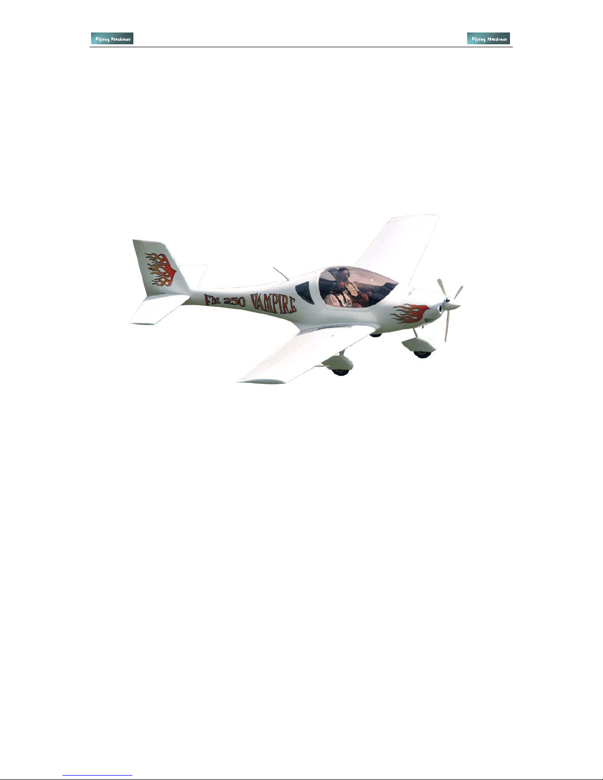
FM-250 Vampire is an all composite ultralight low wing airplane with two seats.
The fuselage has sandwich composite construction, with oval cross section shaped to
achieve the propitious proportion considering rigidity, weight and aerodynamic drag.
The landing gear consists of two main wheels and a nose wheel. The main wheels are
equipped with hydraulic disk brakes. The nose wheel is steerable.
The brakes are hand-operated from both seats using a lever on the center console. The lever
can be locked in the full back position; therefore it can be used as a parking brake.
The wheels can be equipped with fairings.
The cockpit is arranged with side by side seating. It is covered with large, clear or tinted
forward-hinged canopy, which provides an exceptional view. The canopy is held open using
a gas strut and it has two locks on both sides of the canopy. The cockpit is equipped with
ventilation and heating.
FM-250 Vampire has full dual controls consisting of two control sticks, rudder pedals, trimtab lever, throttle, landing flaps and brake levers.
The wing has cantilever all composite construction with one main and one rear auxiliary spar,
which holds ailerons and split landing flaps. The main spars of both wings are joined by two
bolts and rear auxiliary spars are connected to the fuselage by two screws, all fitted in
bearings.
The entire empennage is also all composite construction. The right elevator contains trim-tab.
1.2.2. Fuel system
The fuel system consists of an integrated composite fuel tank in the right wing with fuel level
sender, fuel lines, fuel valve, filter, fuel screen in the tank, drain valve and mechanical fuel
pump. This applies for the engines Rotax 912 and 912S series.
Fuel tank is equipped with a fuel cap located on the top of the right wing.
1.2.3 Engine
Aircraft is powered by Rotax 912 UL or 912 ULS engine, which ensures the airplane’s
excellent dynamic and flying characteristics. Engines Rotax 912 UL and 912 ULS are fourstroke four-cylinder opposed type engines with liquid-cooled cylinder heads and air-cooled
cylinders.
The engine has an integrated reduction gear and two carburetors. More information about
the engine is enclosed in the engine manual.
WARNING
None of the above mentioned engines are certified for aviation use. Even though a
maximum attention is paid during their production, engine failure can occur at any
time. Pilot of the airplane is solely responsible for the consequences.
The obligation of the pilot is to be able to glide and land safely to preselected area in
the case of engine failure.
1.2.4 Propeller
It is possible to use non-adjustable, ground adjustable, in flight adjustable or constant speed
propellers. The description of the propeller is provided with your airplane and is included in
the instructions for assembly and maintenance of the propeller.
Flight Manual Page 6 of 40

www.flyingmachines.cz FLYING MACHINES s.r.o. info@flyingmachines.cz
1.2.5 Landing gear
Landing gear consists of two main composite legs and a welded front leg. The tricycle gear
configuration, steerable nose wheel and hydraulic brakes all combine make the aircraft easy
to handle on the ground.
1.2.6 Controls
Controls are made of AlCu4PbMg and AlCuMg1 aluminum alloys. All controls are fitted in
bearings.
1.2.6.1 Movement of flight controls
Pitch control is effected by fore-aft movement of the control stick. Its movement is transmitted
to elevator using rods.
Pitch trimming is effected by lever installed between the seats right to the throttle. Its
movement is transmitted to trim-tab using cables.
Roll control is effected by sideward movement of the control stick. Its movement is
transmitted to ailerons using rods.
Yaw control is effected by rudder pedals. Their movement is transmited to the rudder using
cables.
Braking is effected by foot operated brakes located on the rudder pedals.
Landings flaps are actuated by a lever installed between the seats behind the throttle and
pitch trim. The most forward position of the lever corresponds to the flaps up position, the
most rearward position of the lever corresponds to the flaps full down position.
Throttle lever is located between the seats left to the pitch trim. The most forward position of
the lever corresponds to full power of the engine, the most rearward position of the lever
corresponds to idle setting of the engine.
1.2.7 Equipment
FM-250 Vampire can be equipped with a wide variety of the instruments ranging from basic
instruments for monitoring flight and engine parameters to the "glass cockpit” incorporating
the latest EFIS’s and MFD’s. The instruments in this airplane contain:
EFIS DYNON D-10A
Digital Engine Monitoring System
fuel level indicator
transceiver Becker
Flight Manual Page 7 of 40
www.flyingmachines.cz FLYING MACHINES s.r.o. info@flyingmachines.cz
1.2.8 Technical drawing
Flight Manual Page 8 of 40

www.flyingmachines.cz FLYING MACHINES s.r.o. info@flyingmachines.cz
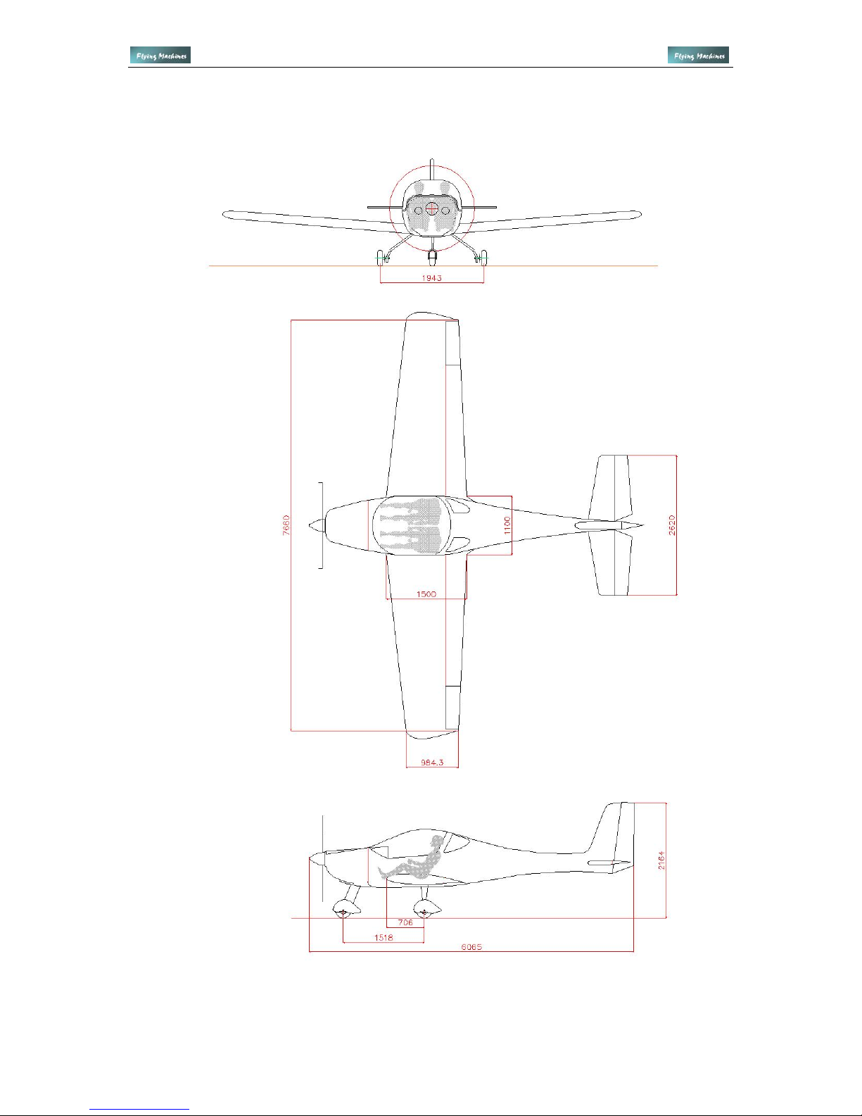
Basic dimensions of FM-250 Vampire
length
height
span
wing area
fuel capacity
tire pressure
6,26 m
2.16 m
7.8 m
10.05 m
2
68 l
1.8 kPa
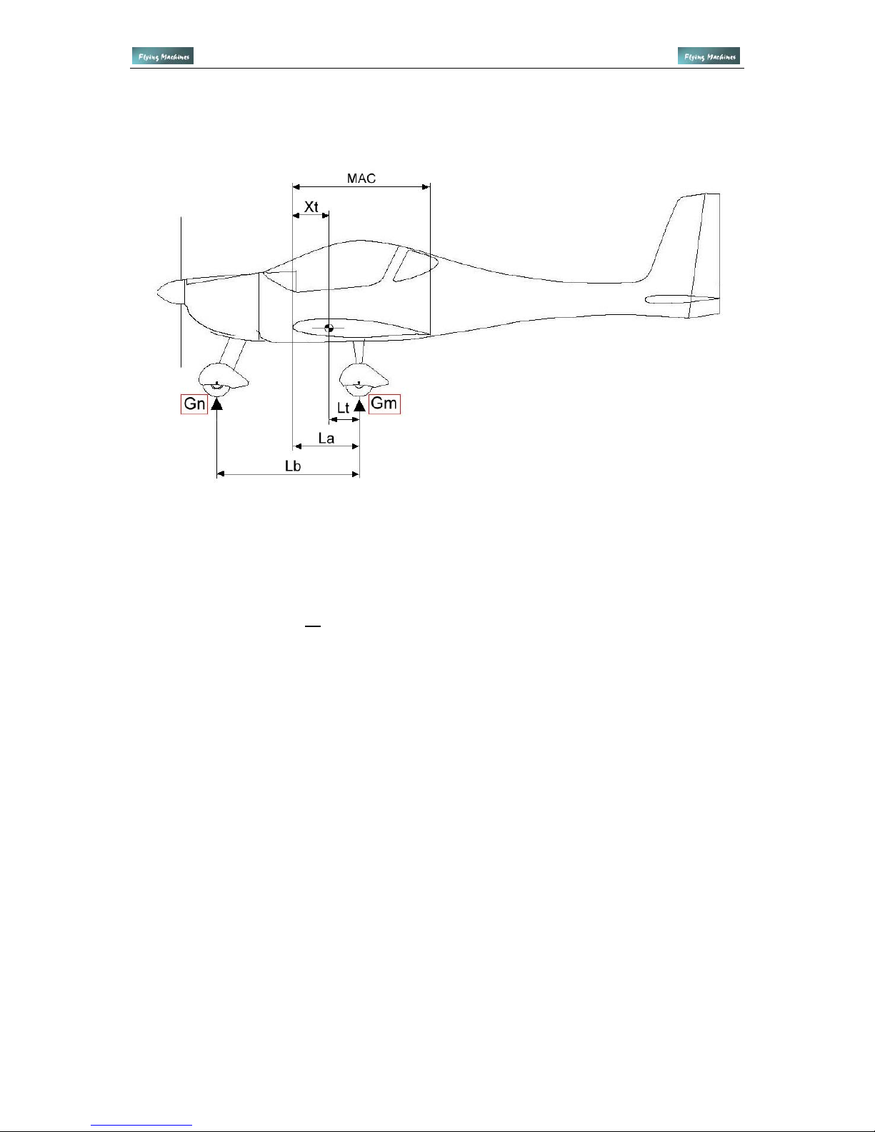
1.2.9 Detecting the position of the center of gravity, permitted limits
Keeping the center of gravity in its limits is a must for the stability and manageability of the
airplane. That’s why it is necessary for every airplane operator/user to know how to diagnose
the center gravity position of the airplane for actual occupancy. Flying outside of the
permitted CG limits at either extreme is potentionally dangerous and should not be attempted
in any circumstance.
When calculating the center of gravity it is necessary to know the length of the central
aerodynamic chord. Calculated center of gravity must be inside the range given by the
producer.
Mean aerodynamic chord (MAC) of the wing 1312 mm
Allowed range of the center of gravity in % MAC 22 - 32 %
The actual CG must always be within permitted limits.
When detecting the center of gravity and making subsequent calculations, let the airplane
stand in flying position at three weighing-machines and proceed following these instructions:
1.2.9.1 Weighing the airplane for the headmost position of the center of gravity
- pilot’s seat is occupied with a pilot with the lowest allowed weight
- there can not be any load in the plane, the fuel tank must be empty
- at the scales read the weight Gm under the main wheels; it is the total weight under both
main wheels Gml+Gmr
- at the scales read the weight Gn under the nose wheel
- total weight of the airplane Gtotal is equal to the sum of Gm+Gn
- measure the distance from the axle of the main undercarriage to the axle of the front wheel
Lb in millimeters
- measure the distance from the leading edge of the wing (using plummet) to the axle of the
main undercarriage La in millimeters
- calculate the distance of the center of gravity from the axle of main undercarriage Lt by the
formula: Lt = Gn x Lb / Gtotal
- calculate the distance of the center of gravity from the leading edge of the wing Xt by the
formula: Xt = La - Lt
-calculate the headmost position of the center of gravity in percents by the formula
X% = Xt x 100 / MAC
1.2.9.2 Weighing the airplane for the backmost position of the center of gravity
Both seats must be occupied with maximum weight of the crew, fuel tank must be full and the
useful load must be of maximum allowed value
The procedure of measuring and weighing is the same as detecting the headmost position of
the center of gravity.
Flight Manual Page 9 of 40
www.flyingmachines.cz FLYING MACHINES s.r.o. info@flyingmachines.cz
Gn =
Gml =
Gmr =
Gtotal =
La =
Lb =
kg
kg
kg
kg
706 mm
1518 mm
Center of Gravity
Lt = Gn x Lb / Gtotal
Xt = La - Lt
X% = Xt x 100 / MAC
Lt = ..... x 1518 / ..... = ....
Xt = 706 – .... = ....
X% = .... x 100 / 1312 = ....%
Flight Manual Page 10 of 40

www.flyingmachines.cz FLYING MACHINES s.r.o. info@flyingmachines.cz
2. Limitations
2.1 Introduction
This chapter contains operational limitations and parameters of the airplane and engine.
2.2 Airspeed indicator markings
The airspeed indicator is color coded to emphasize important airspeed limitations.
Green Arc: Normal Operating Range 78km/h – 240 km/h
The green arc shows the normal operating range of the airplane. The speed at the bottom of
the green arc, abbreviated Vs, is the stall speed with the flaps and landing gear retracted,
power at idle, and the airplane at maximum gross weight. The top of the green arc shows the
high end of the normal operating range, the maximum structural cruising speed, abbreviated
Vno.
Yellow Arc: Caution Range 240 km/h – 270 km/h
The yellow arc represents the caution range—speeds appropriate only in smooth air. The top
of the yellow arc coincides with
Vne, the never-exceed speed of the airplane.
White Arc: Flap Operating Range 65 km/h – 120 km/h
The white arc shows the range of speeds in which it's safe to extend full flaps. The upper limit
of the white arc is called Vfe, maximum flap extended speed. Extending the flaps at higher
speeds could cause their structural damage. The lower limit of the white arc, abbreviated
Vso, is the stalling speed or minimum steady flight speed at maximum gross weight with the
flaps and landing gear in the landing position.
Red Line: Never-Exceed Speed 270 km/h
A red line near the top of the airspeed range marks Vne. Exceeding this speed even in
smooth air could damage the airplane structure.
Flight Manual Page 11 of 40

www.flyingmachines.cz FLYING MACHINES s.r.o. info@flyingmachines.cz
2.3 Operating speeds
Airspeed
km/h
IAS *
Warning
Vne
Vno
Vb
Va
Vfe
Vs
Vso
Never exceed speed
Maximum cruising speed
Maximum speed in
turbulence
Maximum maneuvering
speed
Maximum flap extended
speed
Stall speed / clean
Stall speed / landing
configuration
270
240
216
156
120
78
65
Do not exceed this speed in any
circumstance!
This speed can be exceeded only in smooth
air, use max. 1/3 of full deflections of the
controls.
Maximum speed for the flights in turbulence
and wind gusts
Do not use full deflections of flight controls,
the airplane could be overstressed.
Do not exceed this speed with the flaps
extended
Minimum speed with the flaps retracted
Minimum speed with the flaps full extended
* Indicated Air Speed
2.4 Weight and load factors
2.4.1 Maximum and minimum weights
Maximum take off weight
Maximum landing weight
Maximum weight of the fuel
Maximum load of one seat
Maximum weight of load behind the seats
Minimum weight of the crew
450 kg
450 kg
49 kg
100 kg
8 kg
70 kg
2.4.2 Load factors, flight envelope
Load factors express the load of the airplane while operating with inertial and aerodynamic
forces in respect to its total allowed maximum weight. Airplane FM-250 Vampire is certified
for maximum take off weight 450 kg. The regulation UL 2 also demands the following load
factors.
N1 +4.0
N2 +4.0
N3 -1.5
N4 -2.0
N1, N2, N3, N4 ............. load factors by the diagram V-a (flight envelope)
Flight Manual Page 12 of 40
 Loading...