

cytrynka PDB
User Guide
for power distribution board for zmr/qav/rcx 250 class copters
1

Contents
1. Overview and future list 5
2. Installation 6
3. Hardware on board 9
4. Conversion board pins 15
5. Jumpers 18
2

WARNING!
Read this manual very carefully before you start installation
of our PDB. Incorrect use may result in fully damage of
product, personal property and cause of serious injury.
Operating with current over 60A may damage PDB!
This is high degree complexity hobby product and operating
it requires some basic mechanical and electrical abilities.
Some parts on board may get hot. Don't touch any
electronic components when in operation.
Never connect conductive elements from top to bottom of
board as this may cause of short circuit.
3

1. overview and future list
Overview
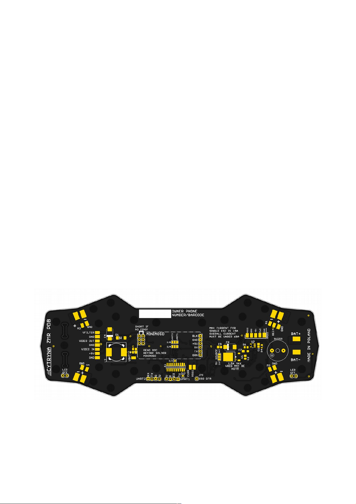
cytrynka PDB is a power distribution board designed for ZMR, QAV or RCX 250 size
frames. It was created because I terribly hate clutter in cables. It's provides to use
direct connections for most of popular FC on market (naze32, CC3D, flip32 etc)
because it using conversion boards. Also on naze32 CB [conversion board] are OSD
with compatibility of minim and kv team software and openlrs (openlrsng software).
Future list
• fits ZMR250, QAV250 and RCX250 frames
• fits with most popular FC on market
• 1.6mm thickness with 70um copper
• current metter (90A)
• high lumen's LED's on front and back
• pins for minimOSD direct connection with user selectable serial port number
(UART1 or UART2)
• pins for UART1 or UART2 (GPS, external telemetry etc)
• pads for all ESC's and main battery
• low-pass PI filter (800mA maximum current) for FPV elements
• PWM to analog converter (RC) for radio link RSSI
• 5V/1.5A voltage regulator
• pads for radio link, video supply (filtered)
• on board buzzer
4
2. installation
Prepare
cytrynka PDB comes completely soldered and you don't need to solder nothing out of
wires for battery, ESC, FPV (OSD including). Also, if you have not ordered CB for CC3D
with wires you need to solder it.
Installation
We recommending to use spacers between bottom plate and our PDB to get best
ventilation.
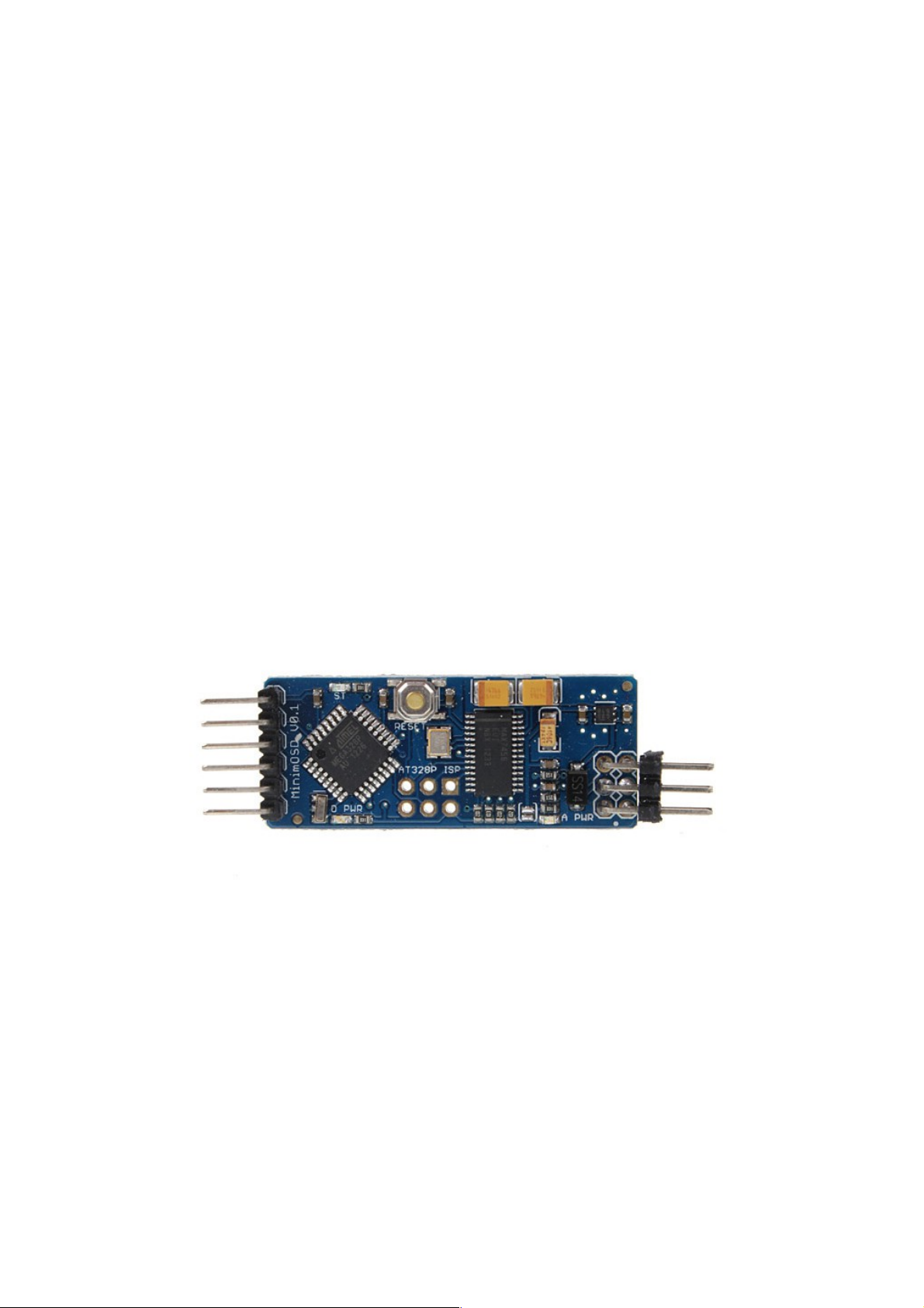
If you use minimOSD is recommended to solder it on beginning. PDB is prepared to
use minimOSD without soldered pins. If you have minim like this on photo you must
remove all pins. Components must be on top. If not minimOSD tie VIN and VOUT pins
on minim video in/out connectors.
Install battery leads with proper gauge for the amount of current you plan on running.
Check two times polarity of battery connectors and pads on PDB. When soldering
ESC's wires to PDB also pay attention with polarity.
Install frame spacer (for top plate). Remember to use nylon screws (attached in
package with cytrynka PDB).
Now you can connect PDB with arms and main bottom plate (our PDB replace top
bottom plate).
5
Flight controller installation
naze32
Using naze32 flight controller with our cytrynka PDB is the best and easiest choice.
User must only solder pins on naze and Conversion Board, connect it together with
PDB, setup in configuration and fly.
Just remember to solder pins on bottom side. Angled pins for PWM outputs must be a
little bit prepared before soldering. Longer side of pins must be shortened about
2mm.
6
WARNING: Never cut pins directly on FC. This may destroy your
gyro. Don't ask why just don't do it
WARNING: Remember to change the orientation in baseflight or
cleanflight by entering the following:
set align_board_yaw = 90
save
Don't forget to check that all the movements are right in the GUI! If
you made a mistake and the movements are not right, your quad will
crash!!

FLIP32(+)
FLIP32(+) flight controller is very similar to NAZE32 and installation is almost the
same.
Just remember to solder pins on bottom side. Angled pins for PWM outputs must be a
little bit prepared before soldering. Longer side of pins must be shortened about
2mm.
7
WARNING: Remember to change the board orientation in baseflight or
cleanflight in yaw axis!

CC3D
CC3D best working with cytrynka PDB when it flashed with latest cleanflight firmware
but it can work with Openpilot software with some limitations (no voltage, current
and RSSI reading).
8
Picture I: Cable colors for CC3D

PORT / CC3D Color Conversion Board Nr / PAD Signal name
Receiver / White cppm / 1 PPM
Receiver / Blue ss tx / 2 Software serial 1 TX pin
Receiver / Yellow ss rx / 3 Software serial 1 RX pin
Receiver / Green current / 4 Current measure pin
Receiver / Orange vbat/ 5
Battery Voltage sensor
Receiver / Purple rssi / 6
RSSI
PORT / CC3D Color Conversion Board PAD Signal name
Main and Flexi / Blue tx UART1/3 TX pad
Main and Flexi / Orange rx UART1/3 RX pad
CC3D Conversion Board have default installed 3.3V regulator for Spektrum Satellite
with JST 1.5mm pitch connector, key transistor for buzzer and resistor voltage divider
for battery voltage measurement.
Motors wiring with OP and Cleanflight firmware
CL and OP have different motor mixing nonetheless in both firmwares user can define
motors mixing but on CB we added jumpers for define which firmware you using.
CC3D Buzzer usage with Openpilot and Cleanflight
Information about using buzzer with CC3D with OP firmware can be found here:
https://wiki.openpilot.org/display/WIKI/Adding+a+Buzzer+to+Your+Vehicle
Before you must solder jumper “Buzzer off” on CB.
With Cleanflight info about buzzer can be found here:
https://github.com/cleanflight/cleanflight/blob/master/docs/Buzzer.md
Don't solder (or desolder) jumper “Buzzer off” on CB.
9
WARNING: All of CC3D's on market are with soldered PINS. Before
using it with cytrynka PDB you must desolder it. It's not simple. Best
solution is to remove first plastics from pins and after that removing
pins one by one.

3. hardware on board
Linear 5V UBEC
cytrynka PDB has an on board 5V linear regulator with maximum current output 1.5A.
It necessary for powering FC, minimOSD or other OSD board, some FPV cameras and
transmitters, GPS and programmable LED's. Also on board are pads for connection
UBEC on one of ESC's and by solder jumper user can chose 5V source (internal or
external not both).
Radio link input pads and RSSI signal converter
On board are solder pads (RSSI, PPM, 5V, RxD, GND) for RC direct connection. Our
PDB for direct connection accepts only PPM sum signal and if your receiver does not
operate with PPM you must use PWM to PPM converter or connect receiver to FC (or
you can use Spektrum Satellite connecting it direct to CB connector). RxD pad is
dedicated for FRSKY telemetry. RSSI signal have PWM to analog RC like this:
RSSI from converter goes to CB and to solder pad and this can be used to connect it
directly to minimOSD (bypassing FC).
10
EXTERNAL 5V UBEC SOLDER PAD
5V SOURCE

11
RC receiver solder pads

Current meter
cytrynka PDB has default on board current sensor with amperage up to 90A.
There are two ways to get current value:
• soldering wire to pad on PDB and directly to OSD. In this case is not possible to
log current value
• using FC (default connection PDB->CB). In this case user must activate feature
in cleanflight configurator:
on image above in “Scale the output...” is “400” but must be 815!
or via CLI using commands:
12
WARNING: Current meter can work with amperage up to 90A but PDB
is designed to carry current only up to 60A.
feature CURRENT_METER
current_meter_type = 1
current_meter_scale = 815
current_meter_offset = 0

minimOSD connector
With our PDB is possible to install minimOSD directly on board. For this purpose
under the FC are pads to solder pins.
MinimOSD can be directly programed with UART2/1 (depending on selected serial
port) connectors on PDB using FTDI programmer. OSD DTR is connected to RESET line
on minim.
If is used other OSD like minim (or with not compatible pinout) short selected pins on
PDB.
For UART2 solder like this: For UART1 solder like this:
13
Solder jumpers for serial
ports selecting for minim.
WARNING: Before soldering minim on PDB select desired serial port
number through solder jumpers. We recommending use UART2. See
below.

For some minims 5V mod needs only shorting this pads:
14
WARNING: Minim used for the cytrynka PDB must have a 5V
modification. See below or check the link:
https://hoogvlieger.wordpress.com/2013/11/01/rctimer-minimosd-5vmod/

Video and LC filtered 12V
For those who wants fly FPV on board are a LC filtered 12V power supply for camera
and video transmitter and video IN/OUT solder pads.
LED diodes
On front and back of PDB are LED diodes- green on front, red on back. All of this are
connected to 12V line. This is simple diodes (not WS2812B or similar). To switch off
lights just remove LED OFF jumper.
15

4. conversion board pins
Pins soldering on conversion boards
Below are photos with correct soldered pins on conversion board for NAZE32 and
FLIP32. Please pay attention to the angle connectors and jumpers.
Naze32
16

FLIP32(+)
17

5. jumpers
jumpers on PDB (main board)
• “LED OFF” - jumper for switching off/on led's on front and back (parallel with
goldpin 2x1),
• SJ6 – solder jumper on bottom side. This is for closing LC filter circuit when
step-down regulator is not installed. With step-down must be open!
• SJ2, SJ3 – jumper for Current Sensor and RSSI signals. Must be close!
• “5V SOURCE” - with this jumper you can select 5V source (internal UBEC or
external with input on pad on M1 connector)
jumpers on NAZE32 conversion board
• SJ5 – selection for UART port number for Spektrum satellite receiver (UART1 or
UART2)
• SJ1 – for S.BUS inverter activation
jumpers on FLIP32(+) conversion board
• SJ2– always open
• SJ1 – for S.BUS inverter activation
• SJ3 – FRSKY input on softserial
jumpers on CC3D conversion board
• solder jumpers group on bottom – this jumpers are for motor mixing selection
dependig firmware on CC3D (OP- openpilot, CF- cleanflight)
• “Buzzer” - closing circuit for buzzer output on SERVO channel (with transistor
key).
18

Some photos of our last installation
19

20
 Loading...