

FLYGT P7030, P7035, P7040 Installation, Operation And Maintenance Manual
Installation, Operation
and Maintenance
Manual
Flygt P7030, P7035, P7040


Table of Contents
Introduction and Safety.........................................................................................................................3
Introduction..........................................................................................................................................3
Safety.....................................................................................................................................................3
Safety terminology and symbols....................................................................................................3
Environmental safety........................................................................................................................4
User safety.........................................................................................................................................5
Product warranty...............................................................................................................................6
Transportation and Storage..................................................................................................................7
Inspect the delivery.............................................................................................................................7
Inspect the package.........................................................................................................................7
Inspect the unit..................................................................................................................................7
Transportation guidelines..................................................................................................................7
Precautions........................................................................................................................................7
Position and fastening......................................................................................................................7
Lifting..................................................................................................................................................7
Temperature ranges for transportation, handling and storage....................................................8
Handling at freezing temperature..................................................................................................8
Unit in as-delivered condition.........................................................................................................8
Lifting the unit out of liquid.............................................................................................................8
Storage guidelines..............................................................................................................................9
Storage location................................................................................................................................9
Long-term storage............................................................................................................................9
Table of Contents
Product Description.............................................................................................................................10
Pump Design.....................................................................................................................................10
Intended Use...................................................................................................................................10
Parts....................................................................................................................................................11
The monitoring equipment..............................................................................................................12
The data plate....................................................................................................................................12
Approvals...........................................................................................................................................13
Product approvals for hazardous locations.................................................................................13
EN approval plate...........................................................................................................................13
IEC approval plate..........................................................................................................................14
FM approval plate..........................................................................................................................14
Product denomination......................................................................................................................14
Installation.............................................................................................................................................16
Fasteners............................................................................................................................................16
Requirements for the cable handling system................................................................................16
Install the pump.................................................................................................................................16
Make the electrical connections......................................................................................................20
General precautions.......................................................................................................................20
Requirements..................................................................................................................................20
Cables..............................................................................................................................................20
Earthing (Grounding).....................................................................................................................21
Cable entry parts............................................................................................................................21
Connect the motor cable to the pump........................................................................................21
Connect the motor cable to the starter and monitoring equipment.......................................22
Power cable phase sequence.......................................................................................................23
Cable charts....................................................................................................................................23
Cable bending radius, weight and diameter..............................................................................30
Flygt P7030, P7035, P7040 Installation, Operation and Maintenance Manual 1

Table of Contents
Check the impeller rotation.............................................................................................................32
Operation..............................................................................................................................................33
Precautions.........................................................................................................................................33
Distance to wet areas........................................................................................................................33
Noise level..........................................................................................................................................33
Start the pump...................................................................................................................................33
Maintenance.........................................................................................................................................35
Precautions.........................................................................................................................................35
Torque values....................................................................................................................................35
Changing the coolant.......................................................................................................................36
Empty the coolant..........................................................................................................................36
Fill with coolant...............................................................................................................................37
Preparing for work on the hydraulic end.......................................................................................38
Remove the entrance cover..........................................................................................................38
Attach the assembly and dismantling stand...............................................................................39
Replacing the propeller....................................................................................................................40
Measure the clearance...................................................................................................................41
Remove the propeller....................................................................................................................42
Install the propeller........................................................................................................................43
Replace the bell mouth....................................................................................................................45
Replace the zinc anodes...................................................................................................................46
Service the pump..............................................................................................................................47
Inspection........................................................................................................................................47
Major overhaul................................................................................................................................49
Service in case of alarm.................................................................................................................49
Troubleshooting...................................................................................................................................50
Introduction.......................................................................................................................................50
The pump does not start..................................................................................................................50
The pump does not stop when a level sensor is used.................................................................51
The pump starts-stops-starts in rapid sequence...........................................................................51
The pump runs but the motor protection trips.............................................................................52
The pump delivers too little or no water........................................................................................52
Technical Reference............................................................................................................................54
Product overview...............................................................................................................................54
Materials.............................................................................................................................................54
Mounting-related data......................................................................................................................55
Operational data...............................................................................................................................56
Application limits............................................................................................................................56
Motor Data......................................................................................................................................56
The monitoring equipment...........................................................................................................56
P7030 Motor rating and performance, 50 Hz...................................................................................57
Low voltage........................................................................................................................................57
P7030 Motor rating and performance, 60 Hz...................................................................................58
Low voltage........................................................................................................................................58
2 Flygt P7030, P7035, P7040 Installation, Operation and Maintenance Manual

Introduction and Safety
Introduction
Purpose of this manual
The purpose of this manual is to provide necessary information for:
• Installation
• Operation
• Maintenance
CAUTION:
Read this manual carefully before installing and using the product. Improper use of the
product can cause personal injury and damage to property, and may void the warranty.
NOTICE:
Save this manual for future reference, and keep it readily available at the location of the
unit.
Introduction and Safety
Safety
WARNING:
• The operator must be aware of safety precautions to prevent physical injury.
• Any pressure-containing device can explode, rupture, or discharge its contents if it is
over-pressurized. Take all necessary measures to avoid over-pressurization.
• Operating, installing, or maintaining the unit in any way that is not covered in this manual
could cause death, serious personal injury, or damage to the equipment. This includes
any modification to the equipment or use of parts not provided by Xylem. If there is a
question regarding the intended use of the equipment, please contact an Xylem
representative before proceeding.
• This manual clearly identifies accepted methods for disassembling units. These methods
must be adhered to. Trapped liquid can rapidly expand and result in a violent explosion
and injury. Never apply heat to impellers, propellers, or their retaining devices to aid in
their removal.
• Do not change the service application without the approval of an authorized Xylem
representative.
CAUTION:
You must observe the instructions contained in this manual. Failure to do so could result in
physical injury, damage, or delays.
Safety terminology and symbols
About safety messages
It is extremely important that you read, understand, and follow the safety messages and
regulations carefully before handling the product. They are published to help prevent
these hazards:
• Personal accidents and health problems
• Damage to the product
• Product malfunction
Flygt P7030, P7035, P7040 Installation, Operation and Maintenance Manual 3

Introduction and Safety
Hazard levels
Hazard level Indication
Hazard categories
DANGER:
WARNING:
CAUTION:
NOTICE:
Hazard categories can either fall under hazard levels or let specific symbols replace the
ordinary hazard level symbols.
Electrical hazards are indicated by the following specific symbol:
A hazardous situation which, if not avoided, will result in
death or serious injury
A hazardous situation which, if not avoided, could result
in death or serious injury
A hazardous situation which, if not avoided, could result
in minor or moderate injury
• A potential situation which, if not avoided, could
result in undesirable conditions
• A practice not related to personal injury
Electrical Hazard:
These are examples of other categories that can occur. They fall under the ordinary hazard
levels and may use complementing symbols:
• Crush hazard
• Cutting hazard
• Arc flash hazard
Environmental safety
The work area
Always keep the station clean to avoid and/or discover emissions.
Waste and emissions regulations
Observe these safety regulations regarding waste and emissions:
• Appropriately dispose of all waste.
• Handle and dispose of the processed liquid in compliance with applicable
environmental regulations.
• Clean up all spills in accordance with safety and environmental procedures.
• Report all environmental emissions to the appropriate authorities.
4 Flygt P7030, P7035, P7040 Installation, Operation and Maintenance Manual

Electrical installation
Recycling guidelines
User safety
General safety rules
Introduction and Safety
WARNING:
Do NOT send the product to the Xylem manufacturer if it has been contaminated by any
nuclear radiation. Inform Xylem so that accurate actions can take place.
For electrical installation recycling requirements, consult your local electric utility.
Always recycle according to these guidelines:
1. Follow local laws and regulations regarding recycling if the unit or parts are
accepted by an authorized recycling company.
2. If the first guideline is not applicable, then return the unit or parts to your Xylem
representative.
These safety rules apply:
• Always keep the work area clean.
• Pay attention to the risks presented by gas and vapors in the work area.
• Avoid all electrical dangers. Pay attention to the risks of electric shock or arc flash
hazards.
• Always bear in mind the risk of drowning, electrical accidents, and burn injuries.
Safety equipment
Use safety equipment according to the company regulations. Use this safety equipment
within the work area:
Electrical connections
Electrical connections must be made by certified electricians in compliance with all
international, national, state, and local regulations. For more information about
requirements, see sections dealing specifically with electrical connections.
Hazardous liquids
The product is designed for use in liquids that can be hazardous to your health. Observe
these rules when you work with the product:
• Hard hat
• Safety goggles, preferably with side shields
• Protective shoes
• Protective gloves
• Gas mask
• Hearing protection
• First-aid kit
• Safety devices
NOTICE:
Never operate a unit unless safety devices are installed. Also see specific information
about safety devices in other chapters of this manual.
• Make sure that all personnel who work with biologically hazardous liquids are
vaccinated against diseases to which they may be exposed.
• Observe strict personal cleanliness.
Flygt P7030, P7035, P7040 Installation, Operation and Maintenance Manual 5

Introduction and Safety
Wash the skin and eyes
Follow these procedures for chemicals or hazardous fluids that have come into contact
with your eyes or your skin:
Condition Action
Product warranty
Coverage
Limitations
Chemicals or hazardous
fluids in eyes
Chemicals or hazardous
fluids on skin
Xylem undertakes to remedy defects in products from Xylem under these conditions:
• The faults are due to defects in design, materials, or workmanship.
• The faults are reported to an Xylem representative within the warranty period.
• The product is used only under the conditions described in this manual.
• The monitoring equipment incorporated in the product is correctly connected and in
use.
• All service and repair work is done by Xylem-authorized personnel.
• Genuine Xylem parts are used.
• Only Ex-approved spare parts and accessories authorized by Xylem are used in Exapproved products.
The warranty does not cover defects caused by these situations:
• Deficient maintenance
• Improper installation
• Modifications or changes to the product and installation made without consulting
Xylem
• Incorrectly executed repair work
• Normal wear and tear
Xylem assumes no liability for these situations:
• Bodily injuries
• Material damages
• Economic losses
1. Hold your eyelids apart forcibly with your fingers.
2. Rinse the eyes with eyewash or running water for at least 15 minutes.
3. Seek medical attention.
1. Remove contaminated clothing.
2. Wash the skin with soap and water for at least 1 minute.
3. Seek medical attention, if necessary.
Warranty claim
Xylem products are high-quality products with expected reliable operation and long life.
However, should the need arise for a warranty claim, then contact your Xylem
representative.
Spare parts
Xylem guarantees that spare parts will be available for 15 years after the manufacture of
this product has been discontinued.
6 Flygt P7030, P7035, P7040 Installation, Operation and Maintenance Manual

Transportation and Storage
Inspect the delivery
Inspect the package
1. Inspect the package for damaged or missing items upon delivery.
2. Note any damaged or missing items on the receipt and freight bill.
3. File a claim with the shipping company if anything is out of order.
If the product has been picked up at a distributor, make a claim directly to the
distributor.
Inspect the unit
1. Remove packing materials from the product.
Dispose of all packing materials in accordance with local regulations.
2. Inspect the product to determine if any parts have been damaged or are missing.
3. If applicable, unfasten the product by removing any screws, bolts, or straps.
For your personal safety, be careful when you handle nails and straps.
4. Contact your sales representative if anything is out of order.
Transportation and Storage
Transportation guidelines
Precautions
WARNING:
• Stay clear of suspended loads.
• Observe accident prevention regulations in force.
Position and fastening
The unit can be transported either horizontally or vertically. Make sure that the unit is
securely fastened during transportation, and cannot roll or fall over.
Lifting
WARNING:
• Crush hazard. The unit and the components can be heavy. Use proper lifting methods
and wear steel-toed shoes at all times.
• Lift and handle the product carefully, using suitable lifting equipment.
• The product must be securely harnessed for lifting and handling. Use eyebolts or lifting
lugs if available.
• Always lift the unit by its lifting handle. Never lift the unit by the motor cable or by the
hose.
• Do not attach sling ropes to shaft ends.
Flygt P7030, P7035, P7040 Installation, Operation and Maintenance Manual 7

Transportation and Storage
Lifting equipment
Lifting equipment is always required when handling the unit. It must fulfill the following
requirements:
• The minimum height (contact Xylem for information) between the lifting hook and the
• The lifting equipment must be able to hoist the unit straight up and down, preferably
• The lifting equipment must be securely anchored and in good condition.
• The lifting equipment must support weight of the entire assembly and must only be
• Two sets of lifting equipment must be used to lift the unit for repair work.
• The lifting equipment must be dimensioned to lift the unit with any remaining pumped
• The lifting equipment must not be oversized.
floor must be sufficient to lift the unit.
without the need for resetting the lifting hook.
used by authorized personnel.
media in it.
NOTICE:
Oversized lifting equipment could cause damage if the unit should stick when being
lifted.
Temperature ranges for transportation, handling and storage
Handling at freezing temperature
At temperatures below freezing, the product and all installation equipment, including the
lifting gear, must be handled with extreme care.
Make sure that the product is warmed up to a temperature above the freezing point before
starting up. Avoid rotating the impeller/propeller by hand at temperatures below the
freezing point. The recommended method to warm the unit up is to submerge it in the
liquid which will be pumped or mixed.
NOTICE:
Never use a naked flame to thaw the unit.
Unit in as-delivered condition
If the unit is still in the condition in which it left the factory - all packing materials are
undisturbed - then the acceptable temperature range during transportation, handling and
storage is: –50°C (–58ºF) to +60°C (+140ºF).
If the unit has been exposed to freezing temperatures, then allow it to reach the ambient
temperature of the sump before operating.
Lifting the unit out of liquid
The unit is normally protected from freezing while operating or immersed in liquid, but the
impeller/propeller and the shaft seal may freeze if the unit is lifted out of the liquid into a
surrounding temperature below freezing.
Units equipped with an internal cooling system are filled with a mixture of water and 30%
glycol. This mixture remains a flowing liquid at temperatures down to –13°C (9°F). Below –
13°C (9°F), the viscosity increases such that the glycol mixture will lose its flow properties.
However, the glycol-water mixture will not solidify completely and thus cannot harm the
product.
Follow these guidelines to avoid freezing damage:
8 Flygt P7030, P7035, P7040 Installation, Operation and Maintenance Manual

1. Empty all pumped liquid, if applicable.
2. Check all liquids used for lubrication or cooling, both oil and water-glycol mixtures, for
the presence of water. Change if needed.
Storage guidelines
Storage location
The product must be stored in a covered and dry location free from heat, dirt, and
vibrations.
NOTICE:
• Protect the product against humidity, heat sources, and mechanical damage.
• Do not place heavy weights on the packed product.
Long-term storage
If the unit is stored more than 6 months, the following apply:
• Before operating the unit after storage, it must be inspected with special attention to
the seals and the cable entry.
• The impeller/propeller must be rotated every other month to prevent the seals from
sticking together.
Transportation and Storage
Flygt P7030, P7035, P7040 Installation, Operation and Maintenance Manual 9

Product Description
Product Description
Pump Design
Intended Use
The product is intended for moving wastewater, sludge, raw and clean water. Always
follow the limits that are given in Application limits (page 56). If there is a question
regarding the intended use of the equipment, please contact a Xylem representative
before proceeding.
WARNING:
In explosive or flammable environments, only use Ex- or MSHA-approved pumps.
NOTICE:
Do NOT use the pump in highly corrosive liquids.
10 Flygt P7030, P7035, P7040 Installation, Operation and Maintenance Manual
Parts
1
2
3
8
7
6
5
4
12
11
10
9
13
WS003673A
15
7
9
14
14
13
Product Description
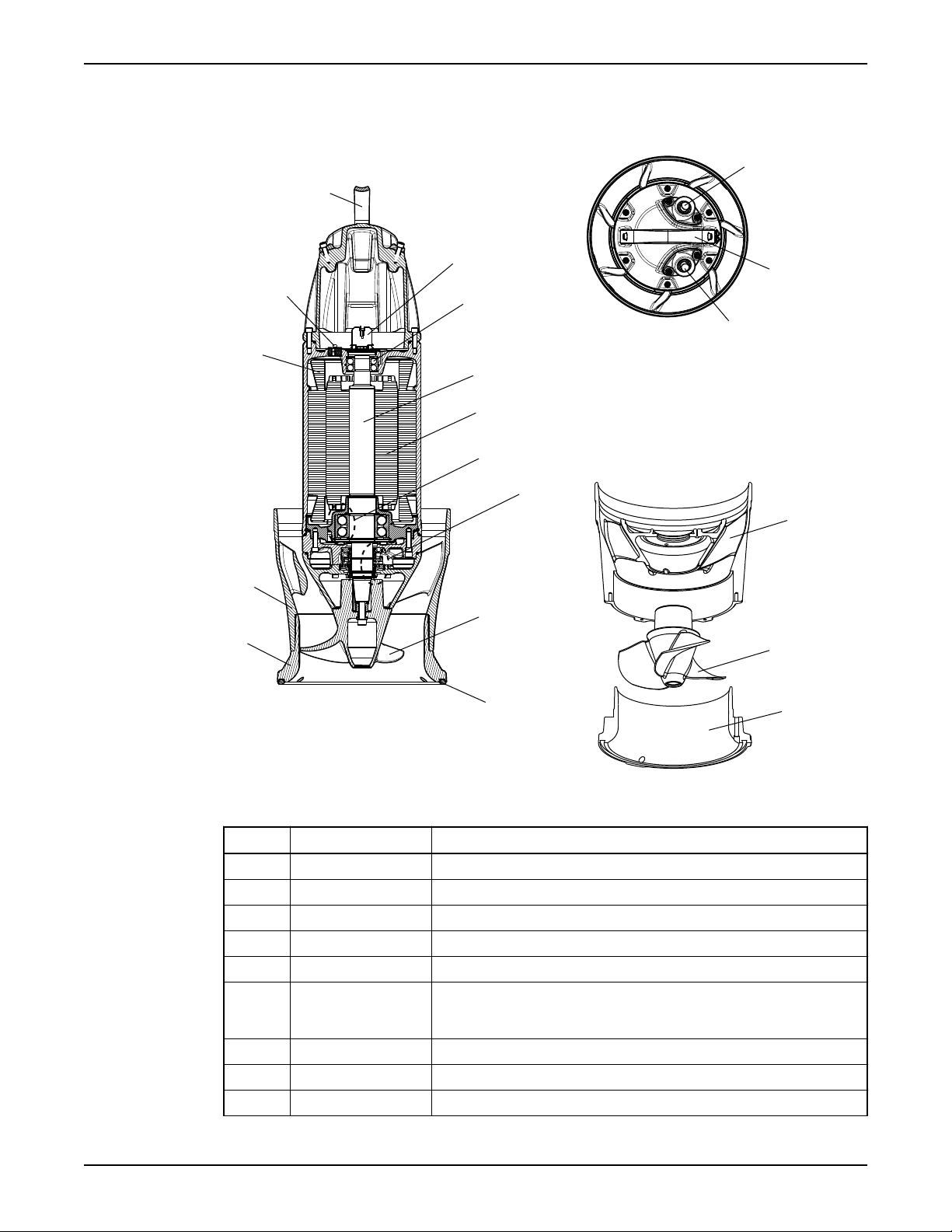
Figure 1: Section view, top view and exploded view of hydraulic parts.
Position Part Description
1 Terminal board
2 Support bearing Two-row ball bearing
3 Shaft Stainless steel, with an integrated rotor
4 Rotor
5 Main bearings Two-row angular contact ball bearing in O-arrangement
6 Seal housing Contains inner and outer mechanical seals. Includes a coolant that lubricates
and cools the seals; the housing acts as a buffer between the pumped fluid
and the electric motor
7 Propeller
8 Seal ring
9 Bell mouth With integrated relief groove
Flygt P7030, P7035, P7040 Installation, Operation and Maintenance Manual 11
2
1312 14
22
21
20
17 18 1916159 10 11
8
7
6
5
4
3
1
23
24
Product Description
Position Part Description
10 Pump housing
11 Stator Equipped with temperature sensors in windings
12 Electrical lead-through
unit
13 Cable entry
14 Lifting handle
15 Guide vanes
Spare part requirements
The following applies when servicing or repairing the pump:
• Modifications to the unit or installation should only be carried out after consulting with
Xylem.
• Original spare parts and accessories authorized by Xylem are essential for compliance.
The use of other parts can invalidate any claims for warranty or compensation. For
more information contact your Xylem representative.
The monitoring equipment
MiniCAS II
The table below shows the parameters which can be tracked with the MiniCAS II
monitoring system.
Parameter Sensor Standard or optional
Stator winding temperature One of the following choices:
Standard
• 3 thermal switches (standard), or
• 3 PTC-thermistors (optional)
Leakage in the inspection chamber Float Switch Leakage Sensor (FLS) Standard
Leakage in the junction box Float Switch Leakage Sensor (FLS) Optional
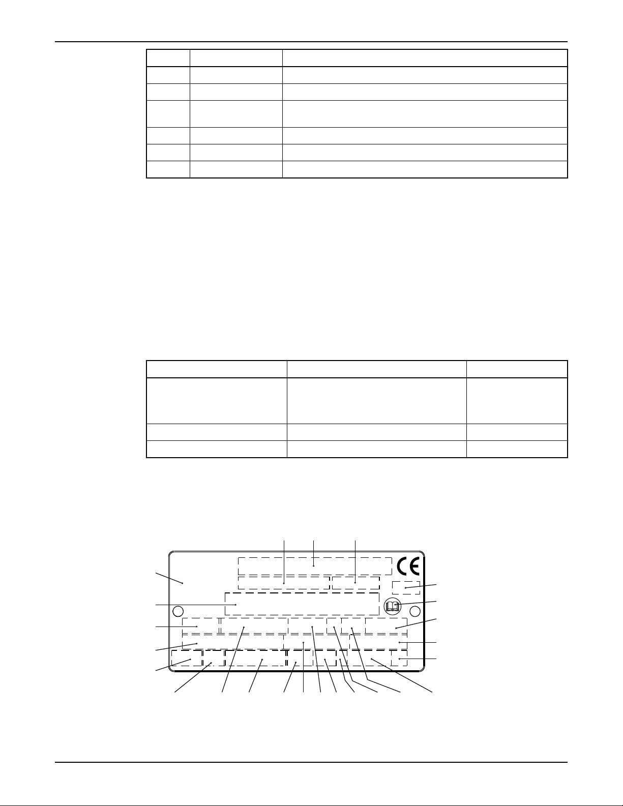
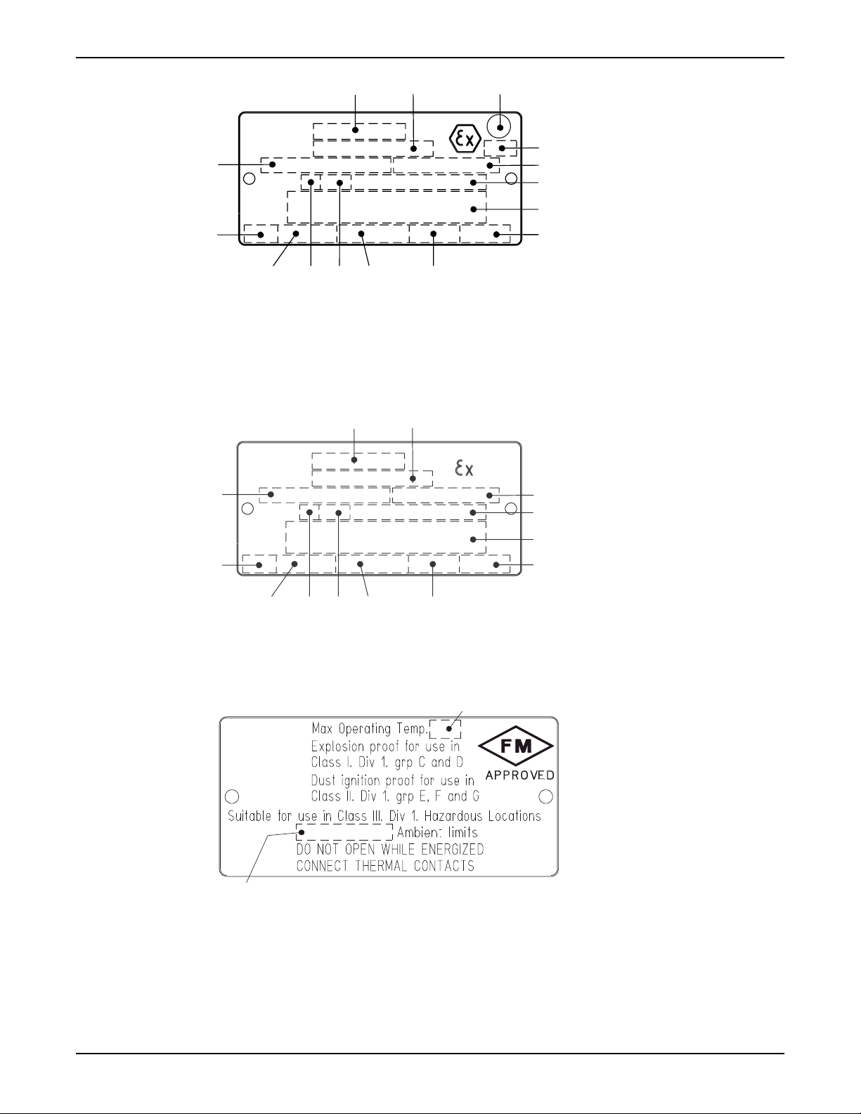
The data plate
The data plate is a metal label located on the main body of the products. The data plate
lists key product specifications. Specially approved products also have an approval plate.
12 Flygt P7030, P7035, P7040 Installation, Operation and Maintenance Manual
1. Curve code/Propeller code
2. Serial number, see Product denomination (page 14)
3. Product number
4. Country of origin
5. Additional information
6. Phase; type of current; frequency
7. Rated voltage
8. Thermal protection
9. Thermal class
10. Rated shaft power
11. International standard
12. Degree of protection
13. Rated current
14. Rated speed
15. Maximum submergence
16. Direction of rotation: L=left, R=right
17. Duty class
18. Duty factor
19. Product weight
20. Locked rotor code letter
21. Power factor
22. Maximum ambient temperature
23. Read installation manual
24. Notified body. Only for EN-approved Ex-products
Figure 2: The data plate
Approvals
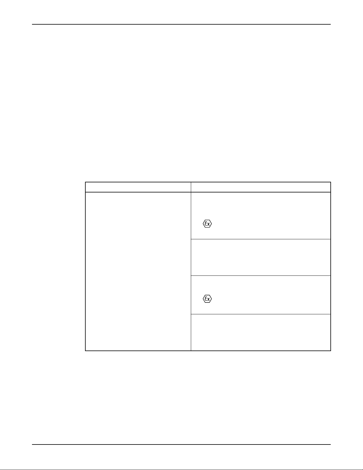
Product approvals for hazardous locations
Pump Approval
Product Description
EN approval plate
7030.090 European Norm (EN)
• ATEX Directive
• EN 60079-0, EN 60079-1, EN 1127-1
•
II 2 G Ex d IIB T3
IEC
• IECEx scheme
• IEC 60079–0, IEC 60079–1
• Ex d IIB T3
EN approval for cable entry:
• Certificate number: INERIS 02ATEX9008 U
•
II 2 G Ex d IIC or I M2 Ex d I
Factory Mutural (FM)
• Class I. Div 1. Group C and D
• Dust ignition proof for use in Class II. Div 1. Group E, F and G
• Suitable for use in Class III. Div 1. Hazardous Locations
This illustration describes the EN approval plate and the information contained in its fields.
Flygt P7030, P7035, P7040 Installation, Operation and Maintenance Manual 13
1 2 3
4
5
6 7
8
9 10
12
11
13
14
15
WS003972A
WS001279B
21
876
3
4
5 9
10
11
12
13
1
2
WS003973A
Product Description
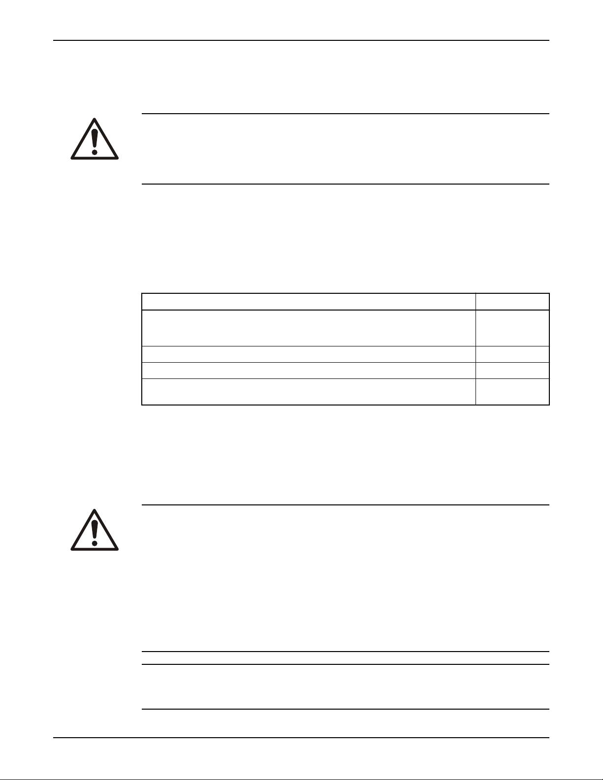
IEC approval plate
1. Approval
2. Approval authority +
approval number
3. Approval for Class I
4. Approved drive unit
5. Stall time
6. Starting current/Rated
current
7. Duty class
8. Duty factor
9. Input power
10. Rated speed
11. Controller
12. Additional information
13. Maximum ambient
temperature
14. Serial number
15. ATEX marking
This illustration describes the IEC approval plate and the information contained in its fields.
International Norm; not for EU member countries.
1. Approval
2. Approval authority +
approval number
3. Approved for drive unit
4. Stall time
5. Starting current/Rated
current
6. Duty class
7. Duty factor
8. Input power
9. Rated speed
10. Controller
11. Additional information
12. Max. ambient temperature
13. Serial number
FM approval plate
This illustration describes the FM approval plate and the information contained in its fields.
1. Temperature class
2. Maximum ambient
temperature
Product denomination
14 Flygt P7030, P7035, P7040 Installation, Operation and Maintenance Manual

Sales denomination
1
NP 3085
2 3
3085.183
1 2
NP
1
NP 3085.183 - 951 0163
2 3 4
Product code
Serial number
Product Description
The sales denomination consists of the four-digit sales code and two letters that indicate
the hydraulic end and type of installation.
This is an example of a sales denomination, and an explanation of its parts.
1. Hydraulic part
2. Installation type
3. Sales code
The product code consists of nine characters divided into two parts.
This is an example of a product code, and an explanation of its parts.
1. Sales denomination
2. Version
The serial number is used for identification of an individual product, and is divided into
four parts.
This is an example of a serial number, and an explanation of its parts.
1. Product code
2. Production year
3. Production cycle
4. Running number
Flygt P7030, P7035, P7040 Installation, Operation and Maintenance Manual 15
Installation
Installation
Fasteners
WARNING:
• Only use fasteners of the proper size and material.
• Replace all corroded fasteners.
• Make sure that all fasteners are properly tightened and that there are no missing
fasteners.
Requirements for the cable handling system
When the pump is installed in a discharge tube, it is critically important that a proper cable
support and protection system is used, especially with long power cables and closed
discharge tubes.
Checklist
This table shows the requirements to be fulfilled by the cable handling system.
Requirement Check
Cables must be supported in such a way, so that they do not come in contact with any hard
surface which could abrade the cable sheathing. Examples of surfaces include pump and tube
components, lifting cables or wires and any other hardware.
Cables should be bundled together, using components that will not cut or abrade the cables.
Proper strain relief and support at prescribed intervals should be provided.
Spring-controlled tensioning and an integrated guide wire system is recommended for long
cables, to protect the cable from movement which can cause damage.
Install the pump
Consult the nearest Xylem representative regarding the following topics:
• Sizing of the pump, piping station, and access frame
• Choice of auxiliary equipment
• Other aspects of installation
WARNING:
• Note that special rules apply to installation in explosive atmospheres.
• Do not install the starter equipment in an explosive zone unless it is explosion-proof
rated.
• Check the explosion risk before welding or using electric hand tools.
• Provide a suitable barrier around the work area, e.g. a guard rail.
• Before installing the pump, check that the cable and cable entry have not been
damaged during transportation.
• A certified electrician must supervise all electrical work. Comply with all local codes and
regulations.
• Make sure that the unit cannot roll or fall over and injure people or damage property.
NOTICE:
• Do not run the pump dry.
• Never force piping to make a connection with a pump.
16 Flygt P7030, P7035, P7040 Installation, Operation and Maintenance Manual
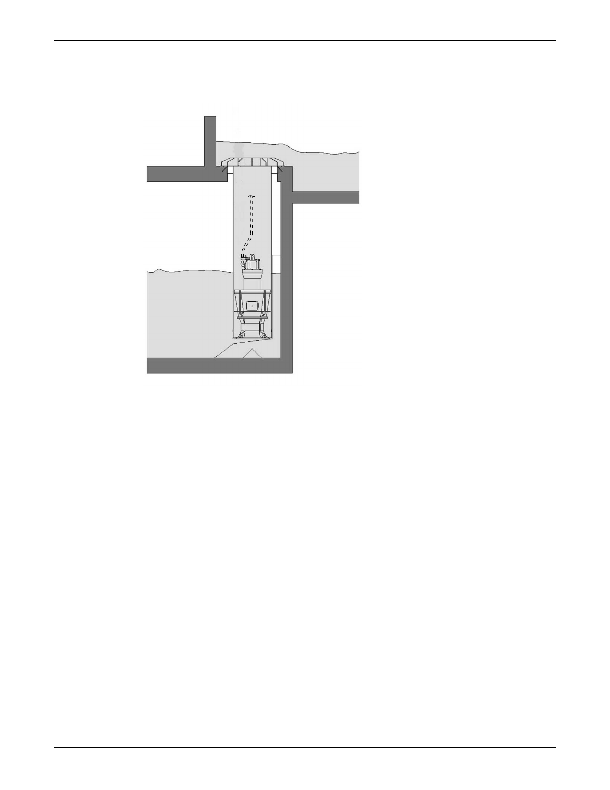
WS001675A
Installation
The pump is usually installed in a vertical discharge tube on a pump seat, which is
incorporated in the lower end of the tube. No anchoring is required because the weight of
the pump is sufficient to keep it in place. The pumps are equipped with anti-rotation
devices.
Figure 3: Pump in discharge tube (generic propeller pump shown)
When the pump is installed in a discharge tube, the following must be considered:
• A suitable cable support and protection system must be used.
Before installation, check the following:
• The propeller must rotate in the correct direction.
If the rotation is not in the correct direction, then the pump may lift and start rotating
inside the tube. This can seriously damage the equipment.
• The rubber seal ring underneath the pump is in place.
• There is no damage to, or debris on, the pump seat.
• There is no large construction debris under the pump tube (at the pump intake). If
debris is present then there is a risk that it can get sucked into the pump and cause
propeller damage.
• The pump control is set to turn the pump off at or above the minimum operating water
level for this pump installation.
1. After cable preparation, lower the pump into the pump column.
Make sure that the pump does not tilt on the stop vanes, which are at the bottom of the
column.
Flygt P7030, P7035, P7040 Installation, Operation and Maintenance Manual 17
 Loading...