

FLYGT MAS 711 Installation And Operation Manual

Installation and Operation
MAS 711
895115/10


Overview
Installation and Operation
MAS 711
Table of
Contents
This publication contains the following topics:
Topic
Preface ............................................................................................................... 7
General Safety Information ................................................................................... 9
Environment.................................................................................................. 10
User Safety and Health...................................................................................11
Warranty ....................................................................................................... 12
Warning Symbols ......................................................................................... 13
Product Description ........................................................................................... 15
System Components ..................................................................................... 16
Configurations............................................................................................... 19
Monitoring Alternatives with ITT Flygt Pumps .................................................. 20
Base Unit Indication....................................................................................... 21
Installation ......................................................................................................... 23
Installation Guideline ..................................................................................... 24
Connect the Unit ........................................................................................... 25
Connect to the Web Tool ............................................................................... 44
First Setup Using the Web Tool ...................................................................... 52
First Setup Using the Operator Panel.............................................................. 55
Use the Web Tool............................................................................................... 57
Use the Operator Panel...................................................................................... 59
Browse the Menus......................................................................................... 60
Menu System................................................................................................ 63
Settings with the Web Tool.................................................................................. 75
Change Password ........................................................................................ 76
Change the Display Language ....................................................................... 77
Set Unit Information....................................................................................... 79
Configure Communication (RS-485, Modbus) ................................................. 80
Make a Manual Setting of a Monitoring Channel ............................................. 82
Record Running Time and Number of Starts .................................................. 84
Compensate for Measurement Error due to Long Leads ................................. 86
Update the Internal Program .......................................................................... 90
Set Reload Time for Alarm and Quick Overview ............................................. 92
Make Settings for Alarm Distribution through E-mail ........................................ 93
Make Modem/PPP Settings ........................................................................... 94
Set Up MAS Network Overview ..................................................................... 96
Set Up MAS Relay Module............................................................................. 97
3

Overview
Settings with the Operator Panel ......................................................................... 99
Change the Display Language ...................................................................... 100
Log in and Change Password........................................................................101
Set Unit Information......................................................................................102
Retrieve Sensor Information from Pump Memory............................................103
Make a Manual Setting of a Monitoring Channel ............................................104
Record Running Time and Number of Starts .................................................105
Check and Change the IP Address................................................................107
Operation ......................................................................................................... 109
Handle Alarms ............................................................................................. 110
View Operation Data..................................................................................... 115
Handle Database Information and Parameters ...............................................126
Handle Pump Information and Service Functions............................................135
Copy Data To/From Pump Memory................................................................139
Trouble Shooting...............................................................................................143
Common Problems and Solutions..................................................................144
Event Messages and Actions ........................................................................ 146
Contact Information .......................................................................................... 149
4

,
Overview
5


Preface
Purpose The purpose of this manual is to give the reader an overview of how to install and set up
the MAS 711.
Recipient The manual is principally intended for ITT Flygt
• service departments
•customers.
and
Product
Documentation
The policy of the ITT Flygt documentation department is to develop as user friendly
product information as possible. Please inform us if this manual
• lacks information that would make the operation of the product easier
• contains information that is irrelevant to the operation of the product.
or
Abbreviations This table shows some of the abbreviations that may be found in this manual:
Abbreviation Meaning
APP Automatic Pump Pilot. Pump controller.
CAS Control And Status. Old pump monitoring system, replaced by MAS.
CLS Capacitive Leakage Sensor. Detects the presence of water in the
oil chamber.
FLS Flygt Leakage Sensor. Float switch for detection of liquid.
FMC Flygt Mactec Control. Pump controller.
MAS Monitoring And Status. Pump monitoring system.
MRM 01
PLC Programmable Logic Controller. General purpose programmable
MAS Relay Module
controller.
VIS10
Vibration sensor
Reference More information about the MAS 711 and how to handle it is available in the following
documents:
• Technical specification, MAS 711 Monitoring system.
• MAS Base unit, Modbus protocol (rev 1,2,3).
• PAN 311/312 User manual.
• MRM 01, Installation and User Manual.
7


Overview
General Safety Information
NOTE!
Table o f
Contents
It is extremely important that you read, understand and follow the warnings and safety
regulations carefully before handling an ITT Flygt product. They are published to
help prevent
• personal accidents and health problems
• damage to the unit
• product malfunction.
ITT Flygt assumes no liability for either bodily injuries, material damages or economic
losses beyond what is stated in this chapter.
This chapter contains the following topics:
Topic
Environment ...................................................................................................... 10
User Safety and Health........................................................................................11
Warranty............................................................................................................ 12
Warning Symbols .............................................................................................. 13
9

General Safety Information,
Environment
Environment
The unit must be installed in an environment that is
• sheltered
• well-ventilated,
• non-hazardous.
Temperature The unit must be used at a temperature within the minimum and maximum rate defined
in accompanying technical data.
Disturbance Ensure that equipment causing serious disturbance is suppressed in the best possible way.
and
10

General Safety Information,
User Safety and Health
User Safety and Health
Introduction All government regulations, local health and safety directives must be observed.
General
electricity
precautions
All danger due to electricity must be avoided. Electrical connections must always be
carried out in compliance with the
• connections shown in the product documentation that is delivered together with the
product,
• electrical regulations locally in force. Reference: For details, consult the regulations
of your local electricity supplier.
Ground the unit: Ground the unit before carrying out any other operation. The electric
pump motor and the panel must be connected to an efficient grounding system in
compliance with the electrical regulations locally in force.
Disconnect the power supply: Always disconnect the power supply before proceeding
to carry out any operation on the electrical or mechanical components of the unit or the
system. Isolate the power supply before opening the pump.
and
High Voltage! Check rated data: Before starting the installation work, check that the rated data of
the automatic control panel is suitable to the mains power supply and the rated data of
the pump.
Isolate power supply before troubleshooting: All trouble shooting must be carried out
with the power supply isolated. If not, the pump could start unexpectedly.
11

General Safety Information,
Warranty
Warranty
Introduction ITT Flygt undertakes to remedy faults in products sold by ITT Flygt if the fault is
• caused by defects in design, materials or workmanship,
• reported to ITT Flygt or ITT Flygt’s representative during the warranty period.
Limitations of validity: The warranty does not cover fault due to the following:
•Deficient maintenance
• Improper installation
•Improperuse
• Incorrectly executed repairs
• Normal wear and tear
and
Qualification
of personnel
All work on the product should be carried out by certified electricians or ITT
Flygt-authorized mechanics.
ITT Flygt disclaims all responsibility for work done by untrained, unauthorized personnel.
Usage The monitoring equipment incorporated in the product must be correctly connected and in
use.
Improper use may cause damage to the equipment and result in warranty cancellation.
Modification Modifications or changes to the product/installation should only be carried out after
consulting with ITT Flygt.
Spare parts Original spare parts and accessories authorized by ITT Flygt are essential for compliance.
The use of other parts can invalidate any claims for warranty or compensation.
Warranty claim For warranty claim, contact your ITT Flygt representative.
Support ITT Flygt only supports products that have been tested and approved. ITT Flygt will not
support unapproved equipment.
12

General Safety Information,
Warning Symbols
Warning Symbols
Symbols In the ITT Flygt documentation, admonitions are used together with the denomination.
The following items describes the safety levels of the admonition symbols in combination
with the denomination.
DANGER!
Risk of causing
• severe injury to people
•death,
• considerable damage to property
if the warning is ignored.
WARNING!
or
NOTE!
High Voltage
Possible risk of causing
• severe injury to people
•death,
• considerable damage to property
if the warning is ignored.
or
CAUTION!
Risk of causing
• injury to people,
• damage to property
if the warning is ignored.
Information that is important for the proper operation of the product, but is not a risk to
the safety of personnel.
Presence of a dangerous voltage.
or
13


Overview
Product Description
Table o f
Contents
This chapter contains the following topics:
Topic
System Components .......................................................................................... 16
Configurations ................................................................................................... 19
Monitoring Alternatives with ITT Flygt Pumps....................................................... 20
Base Unit Indication ........................................................................................... 21
15
Product Description ,
System Components
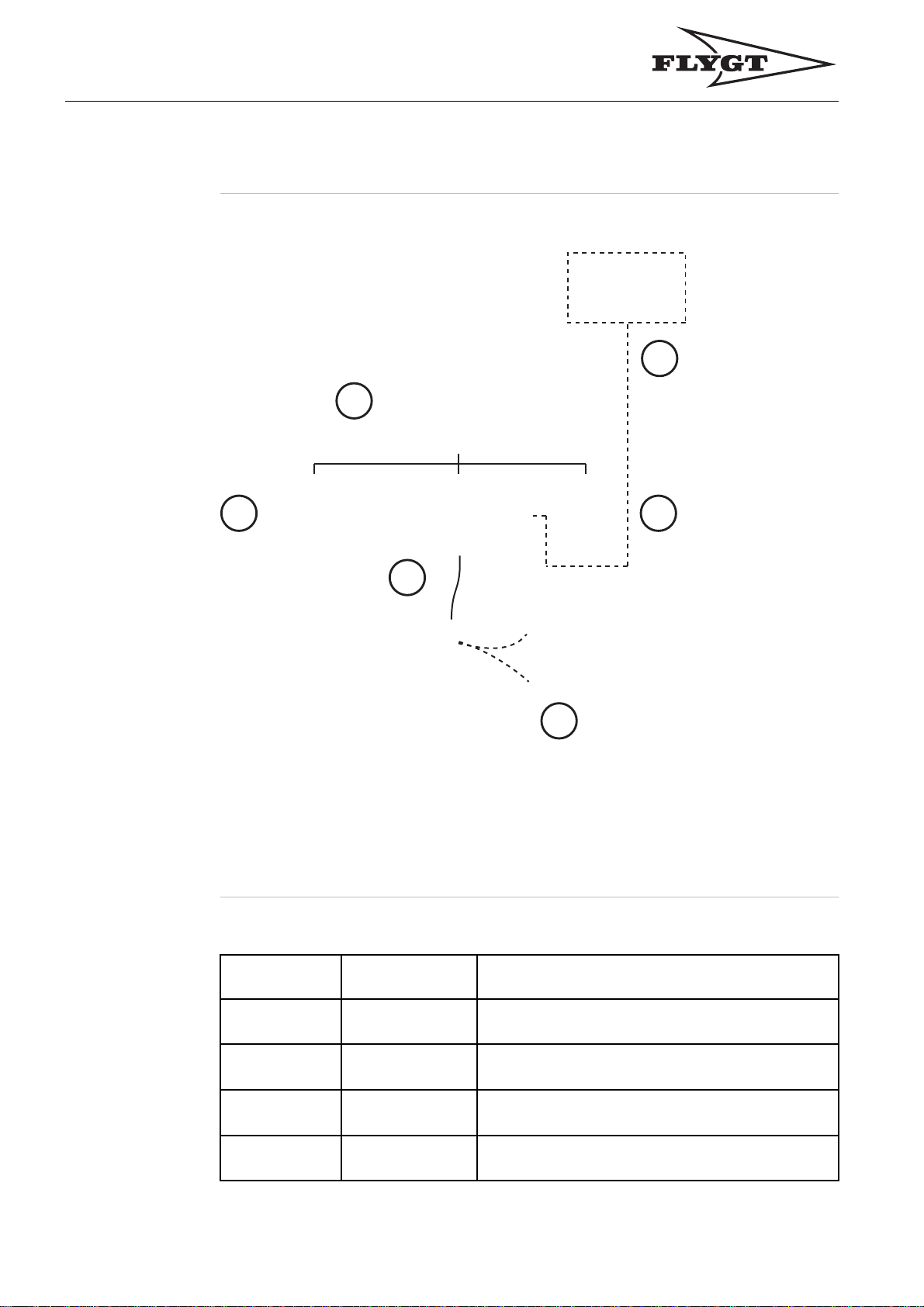
System Components
Illustration
5
1
Component
Description
4
2
This table describes the system components:
Number
Component
6
3
Description
16
1
2Baseunit
3 Pump memory
4 Power analyzer
Operator panel Front panel mounted module used for interaction
with the system.
Contains a powerful processor, memory and
terminals for sensor connections.
Mounted inside the pump and contains information
about the pump.
Optional unit, which measures power, current,
voltage and power factor.

Product Description ,
System Components
Number
5
6 Relay Module
Component
Higher level
system
Possibility to connect to a higher level system
(APP/FMC or PLC) using Modbus.
Optional output unit containing four relays.
Enables communication for individual monitoring
channel alarms (A and/or B alarms) to specific
relays and LEDs on the relay module(s).
Description
Pump Memory The pump memory is an electronic unit mounted in the pump top, containing unique data
about the particular pump it is fitted in. By keeping records in the pump, data cannot be
lost or corrupted when the pump is serviced or moved. The information is used to simplify
installation, service and maintenance of the pump and the monitoring system.
Memory contents
The pump memory contains the following information:
• Data plate information, a fixed part and an editable part
• Pump sensor configuration and settings
• Running statistics
• Service notes
• Service interval
Power
Analyzer
Synchronization and backup
The base unit performs all measurements and data processing in the system. A subset of
all data is also stored in the pump memory. Updated measurement results, parameters or
text are first stored in the base unit and then copied to the pump memory. An automatic
synchronization (update) of the pump memory with the latest information from the base
unit takes place every second hour.
MAS 711 is pre-programmed for use with the optional Power analyzer PAN311/PAN312.
See PAN 311/312 User manual for more information about setup and connection.
The Power analyzer measures:
• Voltage in three phases and system voltage (phase voltage requires connection
“Three phase with neutral”)
• Current in three phases and system current
• Power in each phase and system power
• Power factor
• Energy consumption
Voltage and current unbalance are calculated by the base unit based on data from the
instrument.
MAS will automatically read a selection of registers in the Power analyzer over the
RS-485/Modbus serial data link Ext 2. In this way measured electrical quantities are
recorded and presented on the operator panel and the web tool.
17

Product Description ,
System Components
Higher Level
System
This communication port is dedicated for communication with a higher level system,
meaning for instance a Flygt APP/FMC pump controller or a PLC (Programmable Logical
Controller). The base unit acts as a slave in such a network.
A separate document (MAS Base unit, Modbus protocol) defines in detail how to set up
the communication with the base unit and contains registers used for reading parameters.
Relay Module MAS relay module (MRM 01) is an optional part of the monitoring system. One or more
relay modules (maximum number of 8 modules) can be connected to the base unit through
RS-485 Modbus. This will enable MAS to communicate individual alarms on the separate
monitoring channels (A and/or B alarms) to relays and LEDs on the relay module(s).
The pump sensors will be connected to the base unit and the base unit will monitor the
pump and detect unhealthy conditions. The individual alarms will be transmitted to LEDs
and relays on the MRM 01. The configuration of what alarm that will trigger which relay
on which module is done through the web tool. Sensor configuration, alarm limits and
additional settings are also done in the web tool. See MRM 01, Installation and User
Manual for more information about setup and connection.
Ingress
Protection
The base unit ingress protection is IP20, which means there is no protection against water.
Therefore, it should be mounted inside an electrical cabinet. The operator panel front has
an ingress protection of 65, which means it withstands a water splash or jet if mounted in a
panel or a cabinet door. The back of the operator panel is IP20.
18

Configurations
Product Description ,
Configurations
Configuration
Alternatives
Default
Configuration
for Retrofitof
CAS
Pump and
Application
Specific
Configuration
The system provides two alternative configurations useful for different situations:
• the base unit factory default configuration (for retrofitofCAS)
• a pump specificconfiguration brought by the pump memory.
Since MAS might be used as sparepart for its predecessor CAS or for retrofit (upgrade), it
is factory preset to fit as a CAS substitute. In this factory default configuration the following
monitoring channels are enabled:
• Stator temperature monitoring by means of thermal switches.
• Leakage sensor in the stator housing.
• Leakage sensor in the junction box.
• Main bearing temperature monitoring by means of a Pt100 sensor.
The pump memory which is fitted at the factory, contains information which must be loaded
into the base unit. This makes the system automatically configuredtoreflect the actual
setup of sensors in the particular pump. Default parameters, suitable for the pump such as
alarm limits are also transferred.
Application specific settings can be done either by using the operator panel or by
connecting a computer to the base unit and using the web tool.
or
19

Product Description ,
Monitoring Alternatives with ITT Flygt Pumps
Monitoring Alternatives with ITT Flygt Pumps
Large Pumps ITT Flygt standard monitoring (12-lead SubCab sensor cable)
Large pumps are equipped with a standard set of monitoring sensors to allow safe and
reliable operation. This standard includes large pump models
• 3231
• 3306–3800
• 7061–7121.
This alternative requires 12-lead SubCab sensor cable and includes the following sensors:
• Thermal switches for stator temperature monitoring (3 in series) or PTC-thermistors.
• Leakage sensor in the stator housing.
• Leakage sensor in the junction box.
• Analog temperature sensor (Pt100) for main bearing temperature monitoring.
• Analog temperature sensor (Pt100) for stator winding temperature in one phase.
• Pump memory.
Optional monitoring (24-lead SubCab sensor cable)
Midrange
Pumps
Additional monitoring functions require the use of a 24-lead SubCab sensor cable. The
following options are available:
• Vibration sensor VIS 10.
• Analog temperature sensor (Pt100) for stator winding temperature in phases 2 and 3.
• Leakage sensor in the oil housing (CLS).
• Analog temperature sensor (Pt100) for support bearing temperature monitoring.
Optional monitoring, alternative 1 (12-lead SubCab sensor cable)
The following options are available with midrange pumps (3153, 3171, 3202 and 3301)
and require the use of a 12-lead sensor cable:
• Thermal switches for stator temperature monitoring (3 in series) or PTC-thermistors.
• Leakage sensor in the inspection chamber.
• Leakage sensor in the junction box.
• Analog temperature sensor (Pt100) for main bearing temperature monitoring.
• Analog temperature sensor (Pt100) for stator winding temperature in one phase.
• Pump memory.
Optional monitoring, alternative 2 (12-lead SubCab sensor cable)
Alternative 2 is the same as alternative 1 above but the Leakage sensor in the junction box
is replaced by a Vibration sensor (not available with 3153).
Optional monitoring (25-lead sensor cable)
20
The following additional monitoring functions require the use of a 25-lead sensor cable:
• Vibration sensor VIS 10 and Leakage sensor in the junction box at the same time.
• Analog temperature sensor (Pt100) for stator winding temperature in phases 2 and 3.
• Analog temperature sensor (Pt100) for support bearing temperature monitoring.
Product Description ,
Base Unit Indication
Base Unit Indication
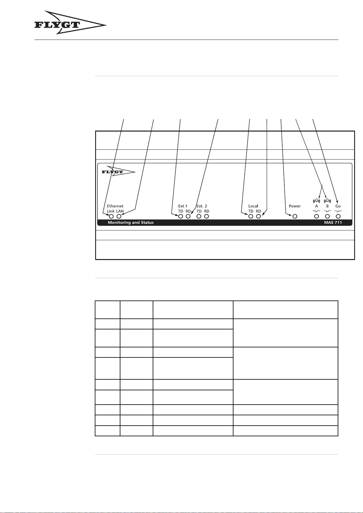
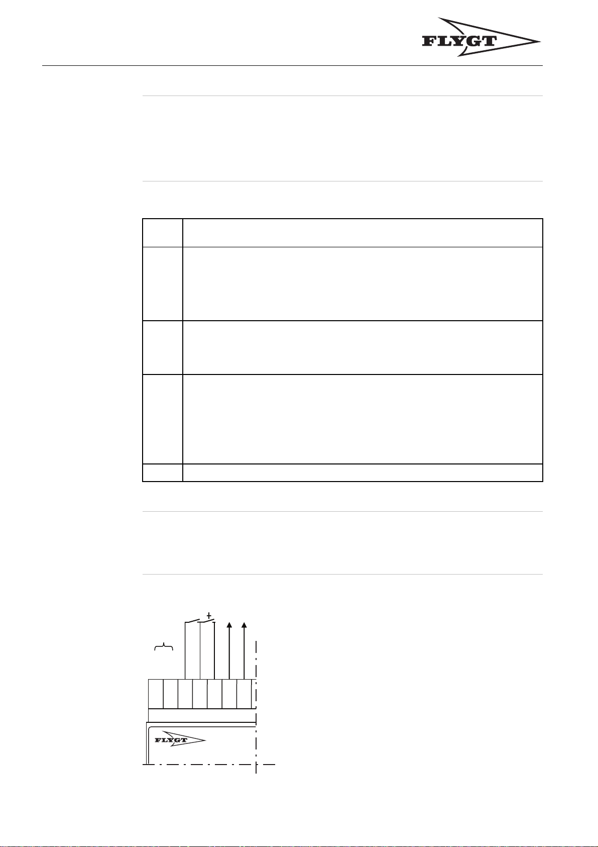
Illustration Light emitting diodes (LEDs) in the front are used for communication and relay indication.
This is an illustration of the base unit LEDs:
123 4
5
697
8
LED Indication
Description
This table describes what the base unit LEDs indicate:
Number
1 Link Ethernet connection status
2 LAN Data communication
3 TD Transmit data
4 RD Receive data
5
6 RD Receive data
7
8
9
LED
name
TD Transmit data
Power Light = Power on Power indication
A/B
Go Green light = OK
Description Type
Ethernet. Connection to LAN or PC
for web access.
indication
Ext. 1/Ext. 2. RS–485/Modbus
communication with APP/FMC
or PLC (Ext. 1) and with Power
analyzer (Ext. 2).
Local. RS–485/Modbus
communication with operator
panel and pump memory.
A = Pump stop, B = Warning Alarm relay indication
Pump contactor interlock relay
21


Overview
Installation
Table o f
Contents
This chapter contains the following topics:
Topic
Installation Guideline .......................................................................................... 24
Connect the Unit ................................................................................................ 25
General Instruction ........................................................................................ 26
Wiring, Supply and Additional Inputs/Outputs .................................................. 28
Wiring, Modbus Communication ..................................................................... 29
Wiring, Relay Outputs.................................................................................... 32
Wiring, Large Pumps, SubCab 12–lead Sensor Cable ..................................... 32
Wiring, Large Pumps, SubCab 24–lead Sensor Cable ..................................... 35
Wiring, Midrange Pumps, SubCab 12–lead Sensor Cable, Alternative 1............ 37
Wiring, Midrange Pumps, SubCab 12–lead Sensor Cable, Alternative 2............ 39
Wiring, Midrange Pumps, 25–lead Sensor Cable ............................................. 41
Connect to the Web Tool .................................................................................... 44
General Instruction ........................................................................................ 44
Make a Direct Connection ............................................................................. 44
Make a LAN Connection ............................................................................... 46
Make a Modem Connection ........................................................................... 50
First Setup Using the Web Tool........................................................................... 52
First Setup Using the Operator Panel .................................................................. 55
23

Installation,
Installation Guideline
Installation Guideline
Guideline This guideline gives an overview of the installation procedure. All steps are described
in detail in the separate sections in the
as an outline.
Follow these steps to make a complete installation and setup:
Installation
chapter. This guideline only serves
Step
1
2
3
4
5
Action
Read the entire chapter
Comment: This is important to prevent injuries to personnel and damages to
the product.
Connect the unit.
Ifyouchoosetousethe
• webtool,gotostep4.
• operator panel, go to step 5.
• Connect to the web tool.
• Makethesetupusingthewebtool.
Result: Thesystemisnowreadytobeused.
Make the setup using the operator panel.
Result: Thesystemisnowreadytobeused.
General Safety Information
.
24

Connect the Unit
Installation,
Connect the Unit
Topics in this
Section
This section contains the following topics:
• General Instruction
• Wiring, Supply and Additional Inputs/Outputs
• Wiring, Modbus Communication
• Wiring, Relay Outputs
• Wiring, Large Pumps, SubCab 12–lead Sensor Cable
• Wiring, Large Pumps, SubCab 24–lead Sensor Cable
• Wiring, Midrange Pumps, SubCab 12–lead Sensor Cable, Alternative 1
• Wiring, Midrange Pumps, SubCab 12–lead Sensor Cable, Alternative 2
• Wiring, Midrange Pumps, SubCab 25–lead Sensor Cable
25
Installation,
General Instruction
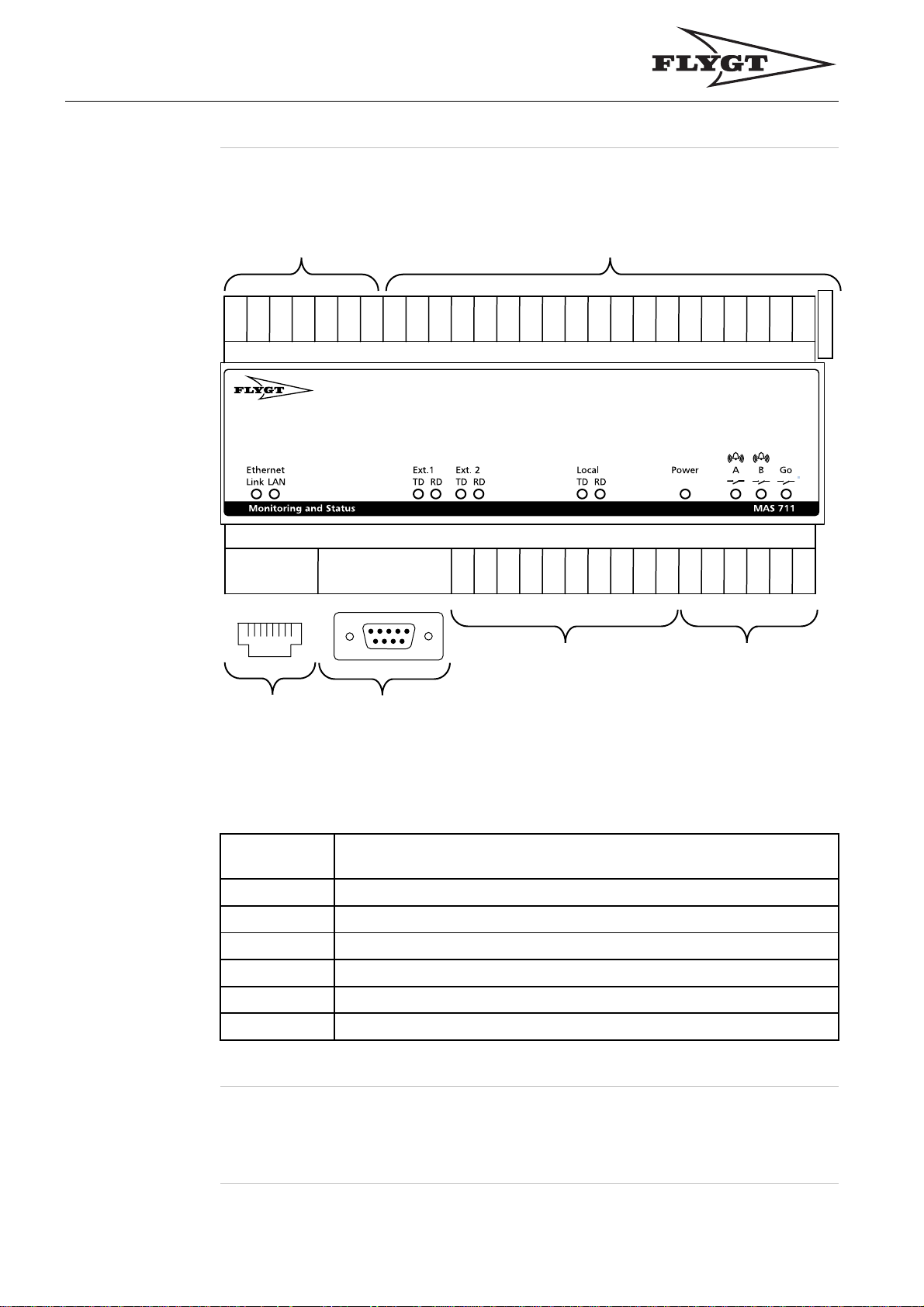
Base Unit
Termi nal Block
12
26
2524232221201918171615
141312
11
10
9
8
7
6
5
4
3
2
1
123
4-567-8
8
123456789
1
42
414039383736353433323130292827
56
34
Terminal block section description
This table describes the main sections of the base unit terminal block:
Section
number
1
2
3
4
5
Description
Supply and additional inputs/outputs
Sensor terminals
Ethernet port (RJ–45)
Serial port (RS–232)
Modbus communication (RS–485)
6 Relay outputs
General Instruction
26
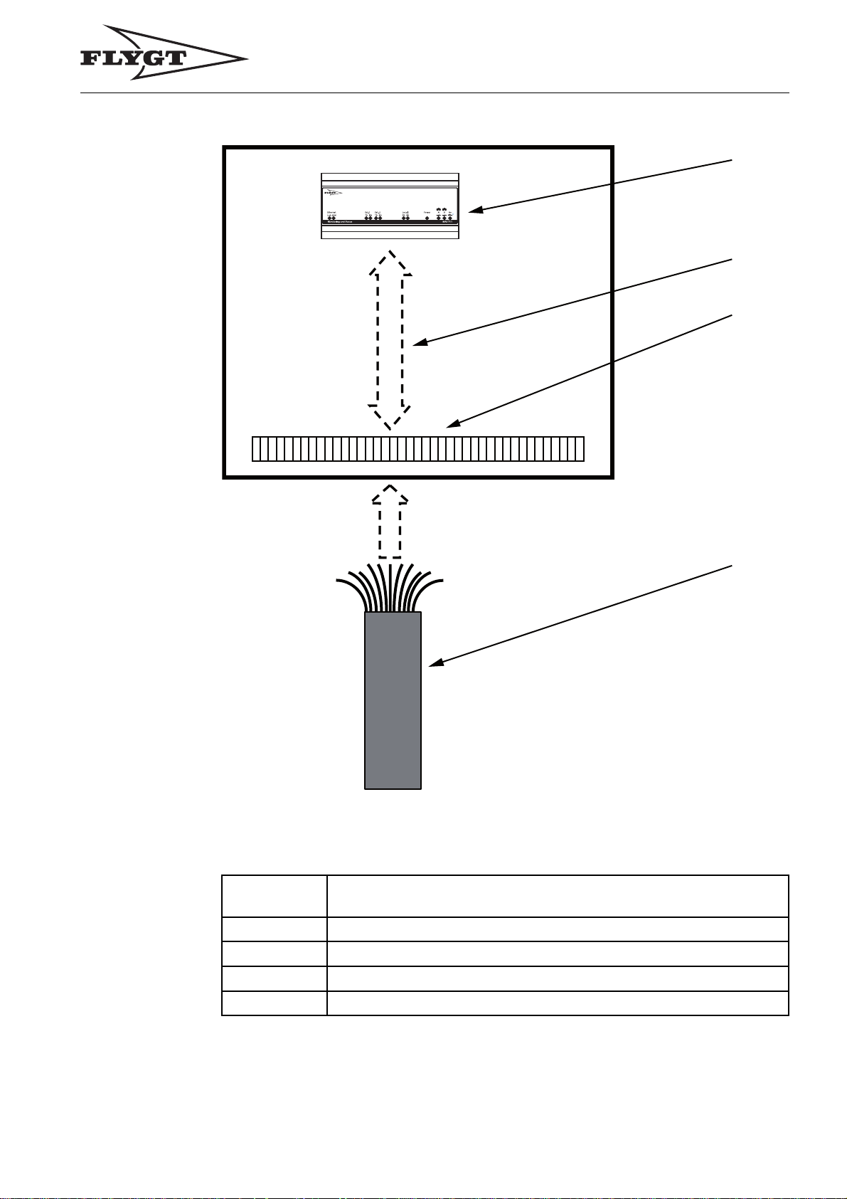
Main Parts
when
Connecting
the Unit
Installation,
General Instruction
1
2
3
Description
This table describes the main parts when connecting the unit:
Section
number
1 Base unit terminal block
2
Description
Cabinet cables
4
3
4
Cabinet connection block
Sensor cable
27
Installation,
Wiring, Supply and Additional Inputs/Outputs
Wiring
diagrams
Use the following wiring diagrams when connecting the unit:
• The wiring diagram of the cabinet.
• The applicable
Wiring
sections below.
Instruction Follow the steps below to connect the unit:
Step
1
Check which number on the cabinet connection block that is connected to
which number on the base unit terminal block. This information is found in the
wiring diagram of the cabinet.
Note! The numbers of the base unit terminal block do
numbers of the cabinet connection block.
2
Connect the wires to the base unit according to the following sections below:
• Wiring, Supply and Additional Inputs/Outputs
• Wiring, Modbus communication
• Wiring, Relay Outputs
3
Identify the applicable sensor configuration and connect the sensor cable to
the cabinet connection block according to the applicable section below:
• Wiring, Large Pumps, SubCab 12–lead Sensor Cable
• Wiring, Large Pumps, SubCab 24–lead Sensor Cable
• Wiring, Midrange Pumps, SubCab 12–lead Sensor Cable, Alternative 1
• Wiring, Midrange Pumps, SubCab 12–lead Sensor Cable, Alternative 2
• Wiring, Midrange Pumps, SubCab 25–lead Sensor Cable
Action
not
have to match the
4 Turn on the voltage to the unit.
Wiring, Supply and Additional Inputs/Outputs
Illustration This is an illustration of section 1 of the base unit terminal block:
/Gnd
–
+
26
2524232221
Gnd
+
20
28

Installation,
Wiring, Modbus Communication
Termi nal
Description
This table describes the terminals for supply and additional inputs/outputs:
Term ina l
number
20
21
22
23
24
25
26
Type Description
+
Ground Configurable output, ground
+
Ground RUN/reset, common ground
+
+
–/ground Supply, ground
Configurable output, 4-20 mA
Reset input
RUN input
Supply, 24 V AC/DC
Wiring, Modbus Communication
Illustration This is an illustration of section 5 of the base unit terminal block:
29
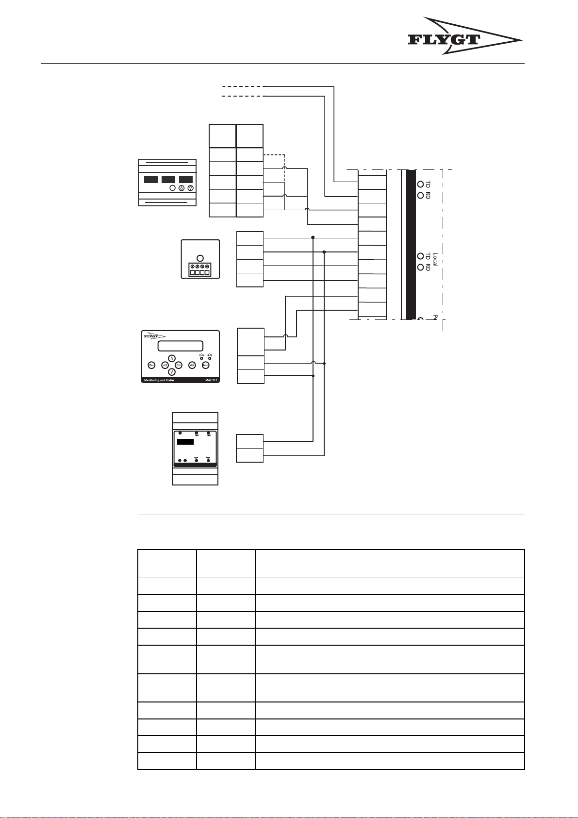
Installation,
Wiring, Modbus Communication
FMC
PLC
.
.
.
PAN
311
11
12
S
13
14
15
PAN
312
7
8
9
10
11
74
75
76
77
42
41
40
39
38
37
36
35
34
33
Ext.2
Base Unit
Termi nal
Description
+
-
A
B
Power
R1
R2
Local
R3 R4
TD RD
Relay mod u le MR M 0 1
This table describes the Modbus communication terminals (RS-485) of the base unit:
Terminal
Type Description
number
33
34
35
+
Ground Supply to Operator panel, ground
+
11
12
Supply to Operator panel, 12 V DC
Supply to Pump memory, 12 V DC
30
36
Ground Supply to Pump memory, ground
37 Local, A
38 Local, B
39 Ext 2, A
40 Ext 2, B
41 Ext 1, A
42 Ext 1, B
RS-485, Operator panel, Pump memory and Relay Module
(Modbus master)
RS-485, Operator panel, Pump memory and Relay Module
(Modbus master)
RS-485, Power Analyzer (Modbus master)
RS-485, Power Analyzer (Modbus master)
RS-485, Central system (Modbus slave)
RS-485, Central system (Modbus slave)
 Loading...